Stair Aid SA-3
37
Operation Manual Stair Aid SA-3
Transcript of Stair Aid SA-3
Operation Manual
Stair Aid SA-3
2
SA-3 12INTRODUCTIONThank you for purchasing STAIR AID, BARTELS POWERED STAIR CLIMBER. This manual describes proper operating procedure, inspection and maintenance. Before running the machine, be sure to read this manual thoroughly. Please keep this manual in the same, easily accessible place.
Ensure that the STAIR AID SA-3 is operated by properly skilled and experienced person only! Never leave stair climber and passengers – except in emergency cases – alone on stairs.
All machines are referred to by their serial numbers. Whenever you inquire about a machine, be sure to inform us of its serial number.The serial number is inscribed on the side of the machine. Please record its number and year, month and date of purchase in the operation manual.
• Type, Serial number QJ SA-3 • Powered stair climber, STAIR AID SA-3
Please write the serial number and date purchased in the following blank space.
Serial number
Date of Purchase Year Month Day
• Only the operator who received training for the operation may operate this product.• STAIR AID is a powered stair climber for transferring a handicapped passenger who cannot
walk up/down the stairs.• STAIR AID is designed to carry one passenger.
Never carry a baby in the arms, have a child on the passenger‘s lap or carry any similar load while using STAIR AID even when the total weight does not exceed STAIR AID‘s maximum load. Unprescribed usage is dangerous.Only one passenger can use STAIR AID while Seat Belt is fastened.
• The operator must call out to the passenger to inform him/her the next action with simple words in order to reduce passenger‘s anxiety before the operator moves STAIR AID to the next phase of the procedure. (Pay special attention to reducing passenger anxiety before and during STAIR AID‘s ascent/descent of the stairs.)
If any of the following situations occur, be sure to inform the sales agency in advance.• The wheelchair installed to STAIR AID has changed.• STAIR AID has been relocated to a different site or transferred.• An untrained operator has to operate STAIR AID.
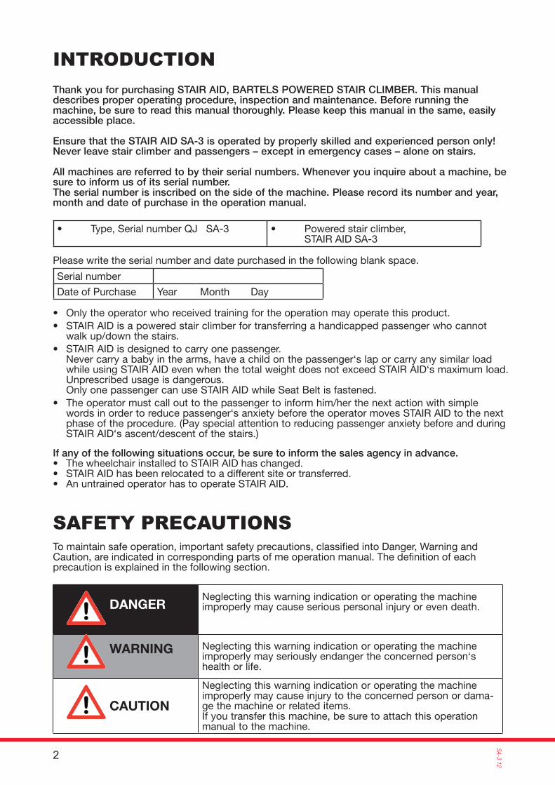
SAFETY PRECAUTIONSTo maintain safe operation, important safety precautions, classifi ed into Danger, Warning and Caution, are indicated in corresponding parts of me operation manual. The defi nition of each precaution is explained in the following section.
DANGER
WARNING
CAUTION
Neglecting this warning indication or operating the machine improperly may cause serious personal injury or even death.
Neglecting this warning indication or operating the machine improperly may seriously endanger the concerned person‘s health or life.
Neglecting this warning indication or operating the machine improperly may cause injury to the concerned person or dama-ge the machine or related items.If you transfer this machine, be sure to attach this operation manual to the machine.
3
SA-3
12
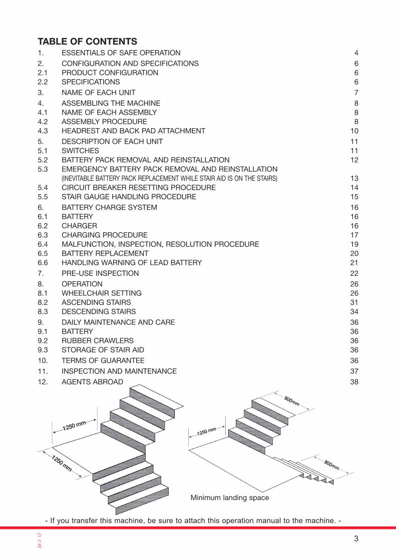
- If you transfer this machine, be sure to attach this operation manual to the machine. -
Minimum landing space
TABLE OF CONTENTS
1. ESSENTIALS OF SAFE OPERATION 4
2. CONFIGURATION AND SPECIFICATIONS 62.1 PRODUCT CONFIGURATION 62.2 SPECIFICATIONS 6
3. NAME OF EACH UNIT 7
4. ASSEMBLING THE MACHINE 84.1 NAME OF EACH ASSEMBLY 84.2 ASSEMBLY PROCEDURE 84.3 HEADREST AND BACK PAD ATTACHMENT 10
5. DESCRIPTION OF EACH UNIT 115.1 SWITCHES 115.2 BATTERY PACK REMOVAL AND REINSTALLATION 125.3 EMERGENCY BATTERY PACK REMOVAL AND REINSTALLATION (INEVITABLE BATTERY PACK REPLACEMENT WHILE STAIR AID IS ON THE STAIRS) 135.4 CIRCUIT BREAKER RESETTING PROCEDURE 145.5 STAIR GAUGE HANDLING PROCEDURE 15
6. BATTERY CHARGE SYSTEM 166.1 BATTERY 166.2 CHARGER 166.3 CHARGING PROCEDURE 176.4 MALFUNCTION, INSPECTION, RESOLUTION PROCEDURE 196.5 BATTERY REPLACEMENT 206.6 HANDLING WARNING OF LEAD BATTERY 21
7. PRE-USE INSPECTION 22
8. OPERATION 268.1 WHEELCHAIR SETTING 268.2 ASCENDING STAIRS 318.3 DESCENDING STAIRS 34
9. DAILY MAINTENANCE AND CARE 369.1 BATTERY 369.2 RUBBER CRAWLERS 369.3 STORAGE OF STAIR AID 36
10. TERMS OF GUARANTEE 36
11. INSPECTION AND MAINTENANCE 37
12. AGENTS ABROAD 38
4
SA-3 12
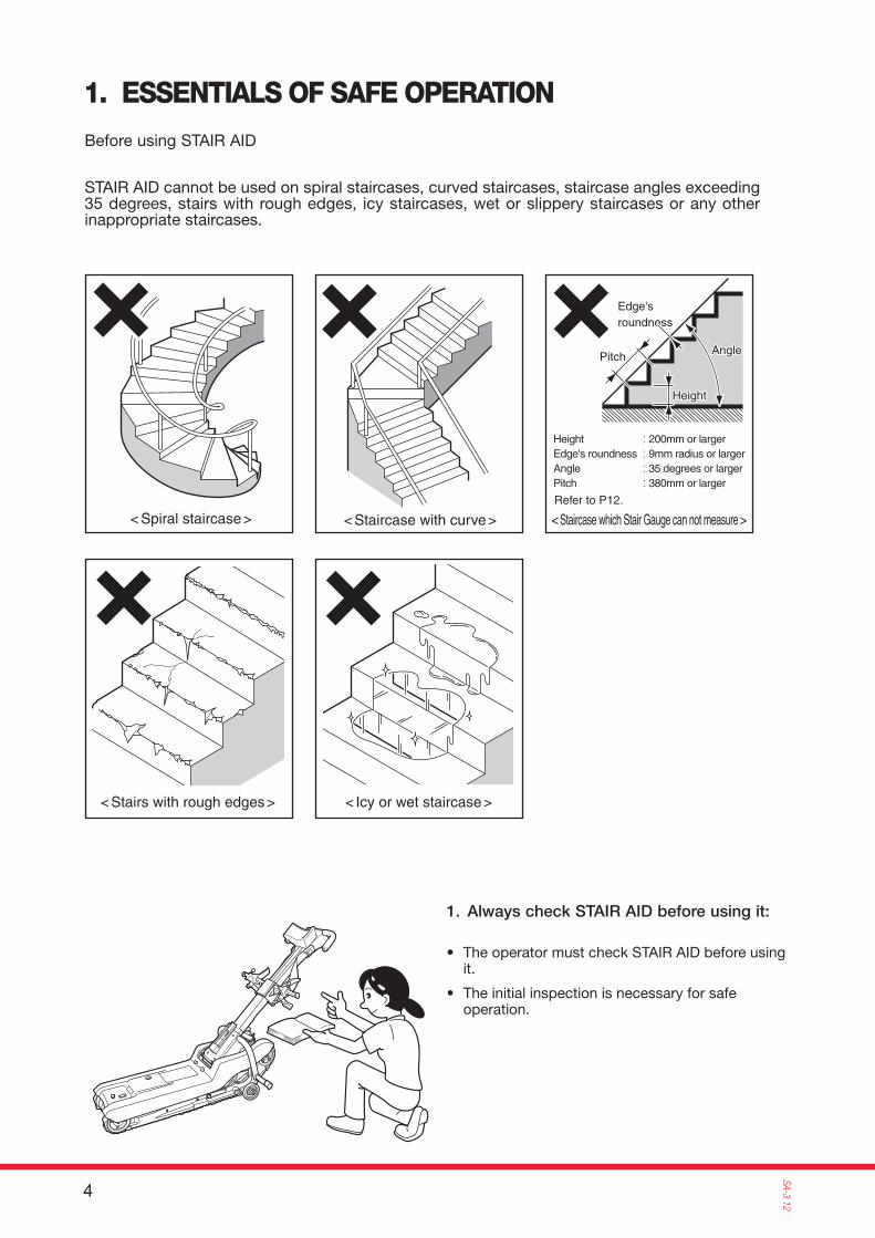
< Spiral staircase > < Staircase with curve >
< Stairs with rough edges > < Icy or wet staircase >
< Staircase which Stair Gauge can not measure >Refer to P12.
Height
AngleAngle
Edge'sroundness
Height
Pitch
Height : 200mm or largerEdge's roundness : 9mm radius or largerAngle : 35 degrees or largerPitch : 380mm or larger
1. ESSENTIALS OF SAFE OPERATIONBefore using STAIR AID
STAIR AID cannot be used on spiral staircases, curved staircases, staircase angles exceeding 35 degrees, stairs with rough edges, icy staircases, wet or slippery staircases or any other inappropriate staircases.
1. Always check STAIR AID before using it:
• The operator must check STAIR AID before using it.
• The initial inspection is necessary for safe operation.
5
SA-3
12
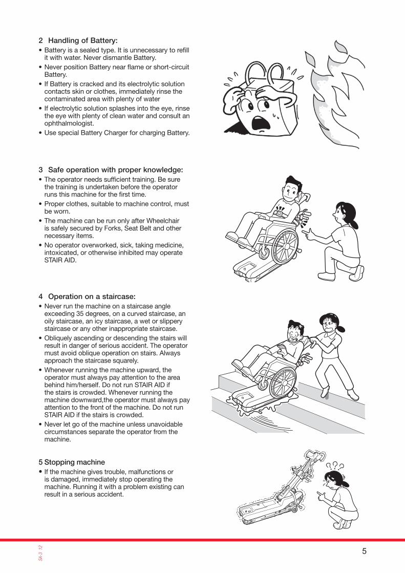
2 Handling of Battery:• Battery is a sealed type. It is unnecessary to refi ll
it with water. Never dismantle Battery.• Never position Battery near fl ame or short-circuit
Battery. • If Battery is cracked and its electrolytic solution
contacts skin or clothes, immediately rinse the contaminated area with plenty of water
• If electrolytic solution splashes into the eye, rinse the eye with plenty of clean water and consult an ophthalmologist.
• Use special Battery Charger for charging Battery.
3 Safe operation with proper knowledge:• The operator needs suffi cient training. Be sure
the training is undertaken before the operator runs this machine for the fi rst time.
• Proper clothes, suitable to machine control, must be worn.
• The machine can be run only after Wheelchair is safely secured by Forks, Seat Belt and other necessary items.
• No operator overworked, sick, taking medicine, intoxicated, or otherwise inhibited may operate STAIR AID.
4 Operation on a staircase:• Never run the machine on a staircase angle
exceeding 35 degrees, on a curved staircase, an oily staircase, an icy staircase, a wet or slippery staircase or any other inappropriate staircase.
• Obliquely ascending or descending the stairs will result in danger of serious accident. The operator must avoid oblique operation on stairs. Always approach the staircase squarely.
• Whenever running the machine upward, the operator must always pay attention to the area behind him/herself. Do not run STAIR AID if the stairs is crowded. Whenever running the machine downward,the operator must always pay attention to the front of the machine. Do not run STAIR AID if the stairs is crowded.
• Never let go of the machine unless unavoidable circumstances separate the operator from the machine.
5 Stopping machine• If the machine gives trouble, malfunctions or
is damaged, immediately stop operating the machine. Running it with a problem existing can result in a serious accident.

6
SA-3 12
External dimensions :
1486mm
69
0m
m
91
8m
m
2. CONFIGURATION AND SPECIFICATIONS
2.1 PRODUCT CONFIGURATION
STAIR AID consists of the following assemblies.
• Handle Unit• Drive Unit• Body Cover• Wheelchair Mount Unit• Headrest
2.2 SPECIFICATIONS
Model SA-3Passenger 1Operator 1
Rubber Crawler 2 Rubber Crawlers (Width: 51mm)
Stair ascent speed 21 steps (6.5 m) / min.Stair descent speed 32 steps (10.0 m) / min.Maximum load 160 kg (Passenger + Wheelchair)
Maximum stair angle 35°
Running time (min) / charge Ascending: 600 steps / 30 min. Descending: 840 steps / 30 min.Battery Maintenance free type sealed lead battery 12V - 20AhCharger Input: 100-240VAC, 50/60Hz, 1.0A MAX 0utput: 12VDC, 3AWeight 65 kg
• Back Pad 1 pc
• Wheels
• Battery Pack
S t a n d a r d accessories
• Charger (12V) 1 unit
• Parts List 1 copy
• Seat Cover 1 sheet
• For ordering the spare Battery Pack, please contact the sales agency.• The additional Back Pad is optional. For ordering the Back Pad, please contact the sales agency.
7
SA-3
12
Pedal Guard
Key Switch
Seat BeltMount Magnet(Both Sides)
Battery PackHook Lever
ChargingReceptacle
Rubber Crawler
ReductionGear
Headrest
Back Pad
Add Back Pad(Option)
Stair Gauge
Kick Bar
Wheelchair Mount Unit
Seat Belt
Fork
Wheelchair Support Tube
Attachment Holder(Both Sides)
Wheel
Body Cover
DC Motor, Electromagnetic Brake
Operation Switch Panel
Control Cable
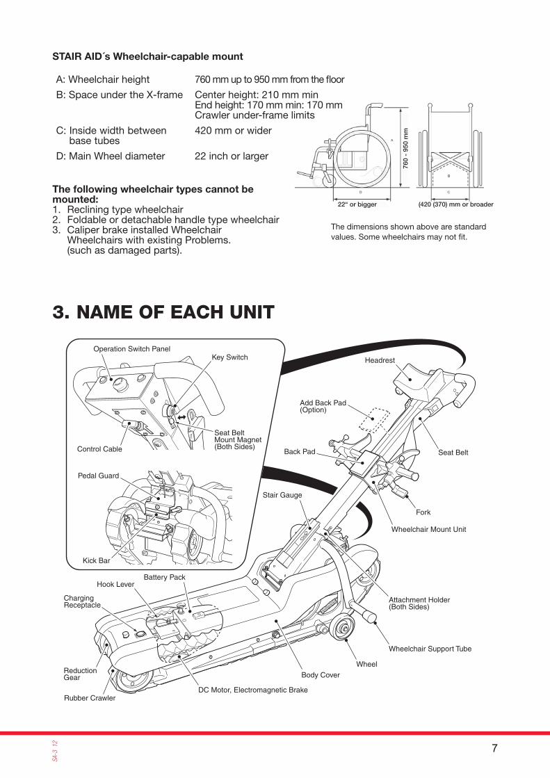
STAIR AID´s Wheelchair-capable mount
22“ or bigger (420 (370) mm or broader
760
- 95
0 m
m
A: Wheelchair height 760 mm up to 950 mm from the fl oor
B: Space under the X-frame Center height: 210 mm minEnd height: 170 mm min: 170 mmCrawler under-frame limits
C: Inside width between base tubes
420 mm or wider
D: Main Wheel diameter 22 inch or larger
The following wheelchair types cannot be mounted:1. Reclining type wheelchair2. Foldable or detachable handle type wheelchair3. Caliper brake installed Wheelchair Wheelchairs with existing Problems.
(such as damaged parts).
The dimensions shown above are standard values. Some wheelchairs may not fi t.
3. NAME OF EACH UNIT
8
SA-3 12
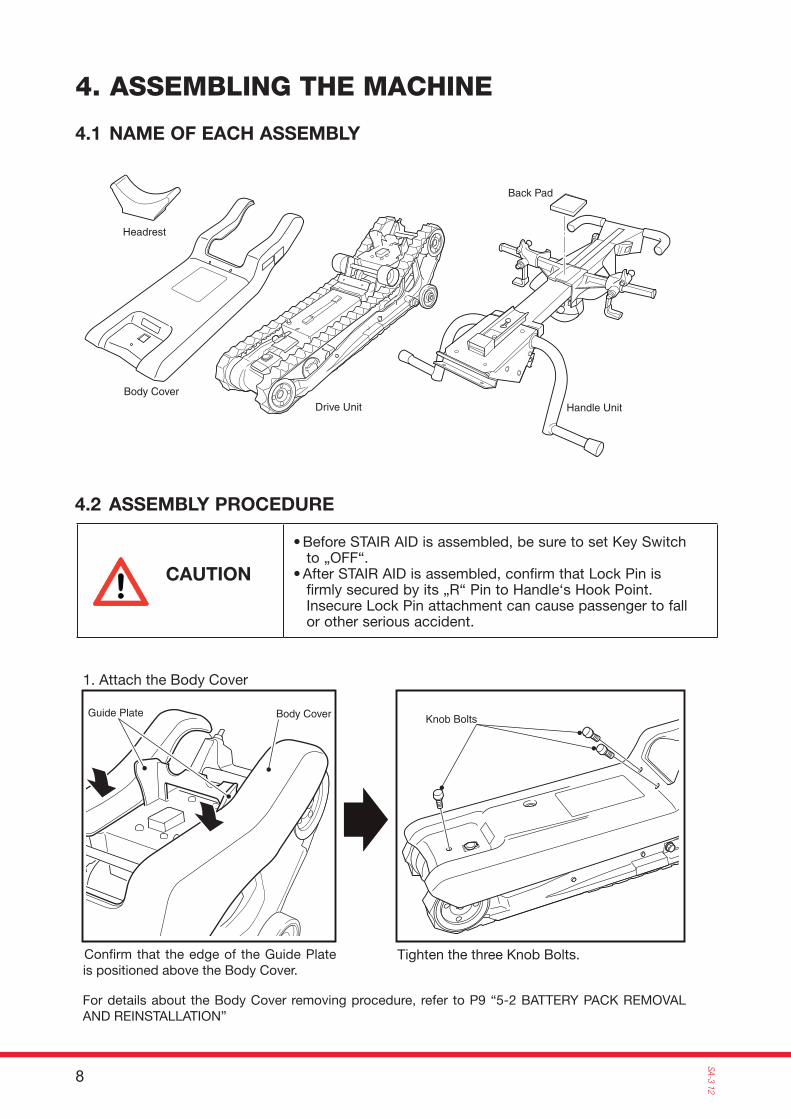
Headrest
Drive Unit
Body Cover
Handle Unit
Back Pad
Guide Plate Body Cover Knob Bolts
• Before STAIR AID is assembled, be sure to set Key Switch to „OFF“.
• After STAIR AID is assembled, confirm that Lock Pin is firmly secured by its „R“ Pin to Handle‘s Hook Point. Insecure Lock Pin attachment can cause passenger to fall or other serious accident.
1. Attach the Body Cover
Confi rm that the edge of the Guide Plate is positioned above the Body Cover.
Tighten the three Knob Bolts.
For details about the Body Cover removing procedure, refer to P9 “5-2 BATTERY PACK REMOVAL AND REINSTALLATION”
4. ASSEMBLING THE MACHINE
4.1 NAME OF EACH ASSEMBLY
4.2 ASSEMBLY PROCEDURE
CAUTION
9
SA-3
12
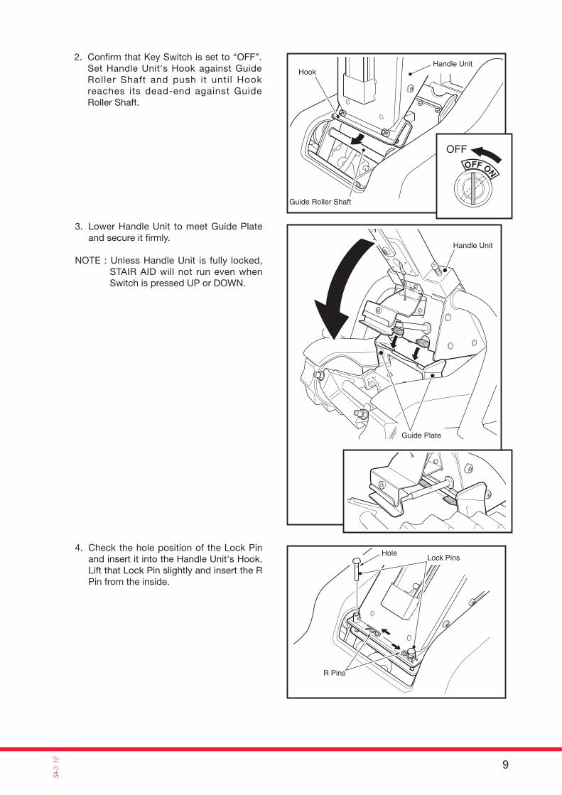
Handle Unit
Guide Roller Shaft
Hook
Handle Unit
Guide Plate
Lock PinsHole
R Pins
OFF
2. Confi rm that Key Switch is set to “OFF”.Set Handle Unit's Hook against Guide Roller Shaft and push it until Hook reaches its dead-end against Guide Roller Shaft.
4. Check the hole position of the Lock Pin and insert it into the Handle Unit's Hook.Lift that Lock Pin slightly and insert the R Pin from the inside.
3. Lower Handle Unit to meet Guide Plate and secure it fi rmly.
NOTE : Unless Handle Unit is fully locked, STAIR AID will not run even when Switch is pressed UP or DOWN.
10
SA-3 12
R Pin
Lock Pin
Headrest
Handle Unit
Velcro Tape
Velcro Tape
Velcro Tape
Handle Unit
Back Pad(Adding)
Back Pad
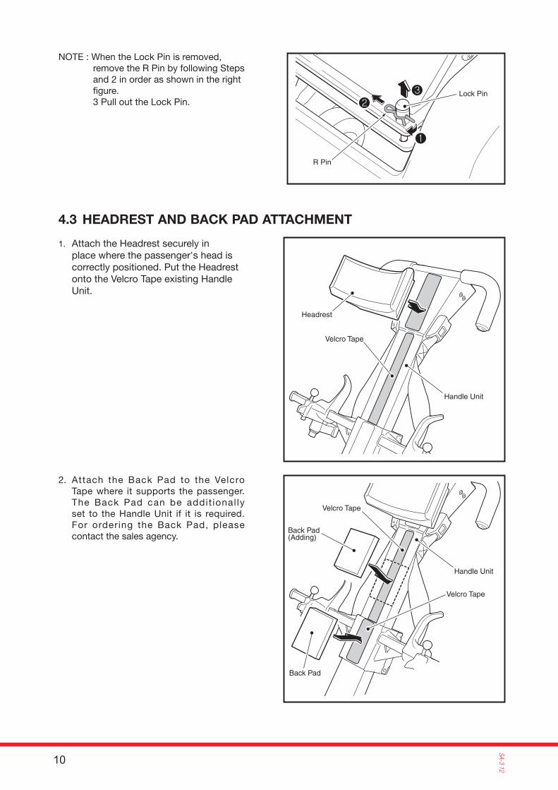
NOTE : When the Lock Pin is removed, remove the R Pin by following Steps and 2 in order as shown in the right fi gure.3 Pull out the Lock Pin.
1. Attach the Headrest securely in place where the passenger's head is correctly positioned. Put the Headrest onto the Velcro Tape existing Handle Unit.
2. Attach the Back Pad to the Velcro Tape where it supports the passenger.The Back Pad can be addit ional ly set to the Handle Unit if it is required.For ordering the Back Pad, please contact the sales agency.
4.3 HEADREST AND BACK PAD ATTACHMENT

11
SA-3
12
Key Switch
UPDOWN
EMERGENCY STOP
POWER
DOWN Push Button (Red)
DOWN Lamp(DOWN Arrow Shaped Lamp)
Power Lamp
Emergency Stop Switch
Battery Gauge
UP Push Button (Green)
UP Lamp(UP Arrow Shaped Lamp)
1. Key SwitchIt turns on/off the power supply. When it is turned clockwise, the power will be ON and when turned counter-clockwise, the power will be OFF.Confi rm that Power Lamp will glow when the power is ON.
NOTE : When STAIR AID is not to be used (to be stored, to be charged, to be transported), turn off Key Switch, remove Key and keep it in an appointed place.
2. UP/DOWN Push ButtonThese Buttons allow STAIR AID to go UP/DOWN the stairs.When UP Button (color: Green) is pressed, the machine will ascend.When DOWN Button (color: Red) is pressed, the machine will descend.
3. Emergency Stop SwitchWhen this Switch is pressed, the machine will stop immediately. STAIR AID won't restart. Even when the other Switch is pressed. The Power Lamp will go off.To release the emergency stop condition, tum Emergency Stop Switch in the “arrow” indicated direction.
4. Power LampWhen the power is supplied, this lamp will glow.(The UP/DOWN operation will be available.)
5. UP Lamp (UP directional shaped arrow), DOWN Lamp (DOWN directional shaped arrow)When the corresponding button is pressed, the lamp will glow.
6. Battery GaugeRefer to P21.
5. DESCRIPTION OF EACH UNIT
5.1 SWITCHES
If Key Switch is kept in the ON position, Battery will more quickly discharge.
When the machine is not to be in use, be sure to turn off Key Switch and remove it.
CAUTION
12
SA-3 12
Knob Bolts
Body CoverEach SideGuide Plate
Body Cover
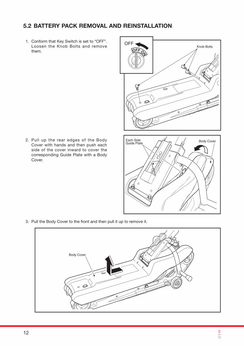
OFF1. Conform that Key Switch is set to “OFF”.Loosen the Knob Bolts and remove them.
2. Pull up the rear edges of the Body Cover with hands and then push each side of the cover inward to cover the corresponding Guide Plate with a Body Cover.
3. Pull the Body Cover to the front and then pull it up to remove it.
5.2 BATTERY PACK REMOVAL AND REINSTALLATION

13
SA-3
12
Locked Position
Hook Lever
Battery Pack
Handle
Battery PackRed Mark Stickers
Be Careful !Low Clearance
4. Turn the Hook Lever at the front of the Battery Pack counter-clockwise to release the battery Pack.
5. Pull the Battery Pack upward by holding the Battery Pack's Handle and then remove it by tilting and pulling it to the front.
6. The battery Pack installation procedure is the reverse procedure of Battery Pack removal.Press the front side of the Battery Pack securely in order to contact the Battery Pack's Power Connector to the STAIR AID's Receptacle.When the Battery Pack is securely installed, turn the Hook Lever clockwise to lock the Battery Pack.
NOTE: Pay attention not to install the Battery Pack in reverse.(Set the Battery Pack's Red Mark with the STAIR AID's Red Mark.)
First, inform the passenger of initiating the replacement of the Battery.
1. Stop STAIR AID so that the number of the Rubber Crawlers contacting points with the stairs is at its maximum.
2. Loosen three Knob Bolts. Remove the two Knob Bolts at back first. Do not remove the front Knob Bolt at this time.
3. Pull up both rear edges of the Body Cover with hands. Then push both sides of the cover inward in order for them to be positioned at the inside of the Body Cover. (Refer to 5-2 (2.), P9)
4. Remove the front Knob Bolt, pull the cover out to the front, and pull up the cover to remove it.
If Battery Pack is dropped, Battery may be damaged.Pay attention to safe handling during Battery removal/reinstallation.
CAUTION
5.3 EMERGENCY BATTERY PACK REMOVAL AND REINSTALLATION (INEVITABLE BATTERY PACK REPLACEMENT WHILE STAIR AID IS ON THE STAIRS)
14
SA-3 12
Set the Battery Pack's Red Mark to come to the Red Mark on the machine
Black Button
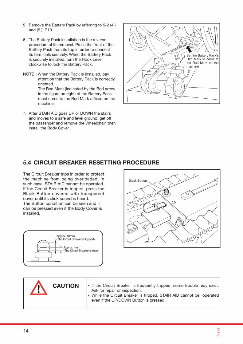
5. Remove the Battery Pack by referring to 5-2 (4.)and (5.), P10.
6. The Battery Pack installation is the reverse procedure of its removal. Press the front of the Battery Pack from its top in order to connect its terminals securely. When the Battery Pack is securely installed, turn the Hook Lever clockwise to lock the Battery Pack.
NOTE : When the Battery Pack is installed, pay attention that the Battery Pack is correctly oriented.The Red Mark (indicated by the Red arrow in the fi gure on right) of the Battery Pack must come to the Red Mark affi xed on the machine.
7. After STAIR AID goes UP or DOWN the stairs and moves to a safe and level ground, get off the passenger and remove the Wheelchair, then install the Body Cover.
The Circuit Breaker trips in order to protect the machine from being overloaded. In such case, STAIR AID cannot be operated.If the Circuit Breaker is tripped, press the Black Button covered with transparent cover until its click sound is heard.The Button condition can be seen and it can be pressed even if the Body Cover is installed.
Approx. 4mm(The Circuit Breaker is reset)
Approx. 10mm(The Circuit Breaker is tripped)
5.4 CIRCUIT BREAKER RESETTING PROCEDURE
• If the Circuit Breaker is frequently tripped, some trouble may exist. Ask for repair or inspection.
• While the Circuit Breaker is tripped, STAIR AID cannot be operated even if the UP/DOWN Button is pressed.
CAUTION
15
SA-3
12
Stair Gauge
Stair Gauge
200m
m
200m
mor
und
er
380mm
35 degreesor larger
380mm or smaller
Pointer
Black Line
Green Zone
Smaller than 9mm radius
Edge's Roundness
Round Hole
Round Hole
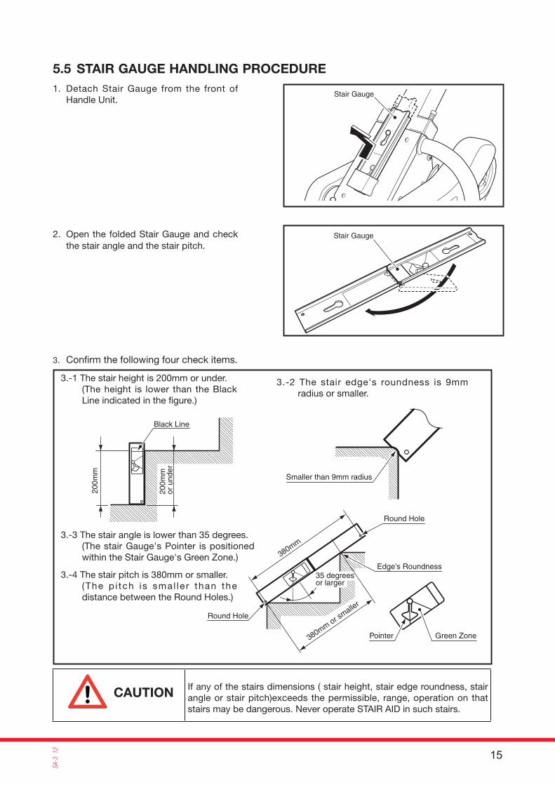
1. Detach Stair Gauge from the front of Handle Unit.
2. Open the folded Stair Gauge and check the stair angle and the stair pitch.
3. Confi rm the following four check items.
3.-1 The stair height is 200mm or under.(The height is lower than the Black Line indicated in the fi gure.)
3.-3 The stair angle is lower than 35 degrees.(The stair Gauge's Pointer is positioned within the Stair Gauge's Green Zone.)
3.-4 The stair pitch is 380mm or smaller.(The p i tch is smal le r than the distance between the Round Holes.)
3.-2 The stair edge's roundness is 9mm radius or smaller.
5.5 STAIR GAUGE HANDLING PROCEDURE
If any of the stairs dimensions ( stair height, stair edge roundness, stair angle or stair pitch)exceeds the permissible, range, operation on that stairs may be dangerous. Never operate STAIR AID in such stairs.
CAUTION
16
SA-3 12
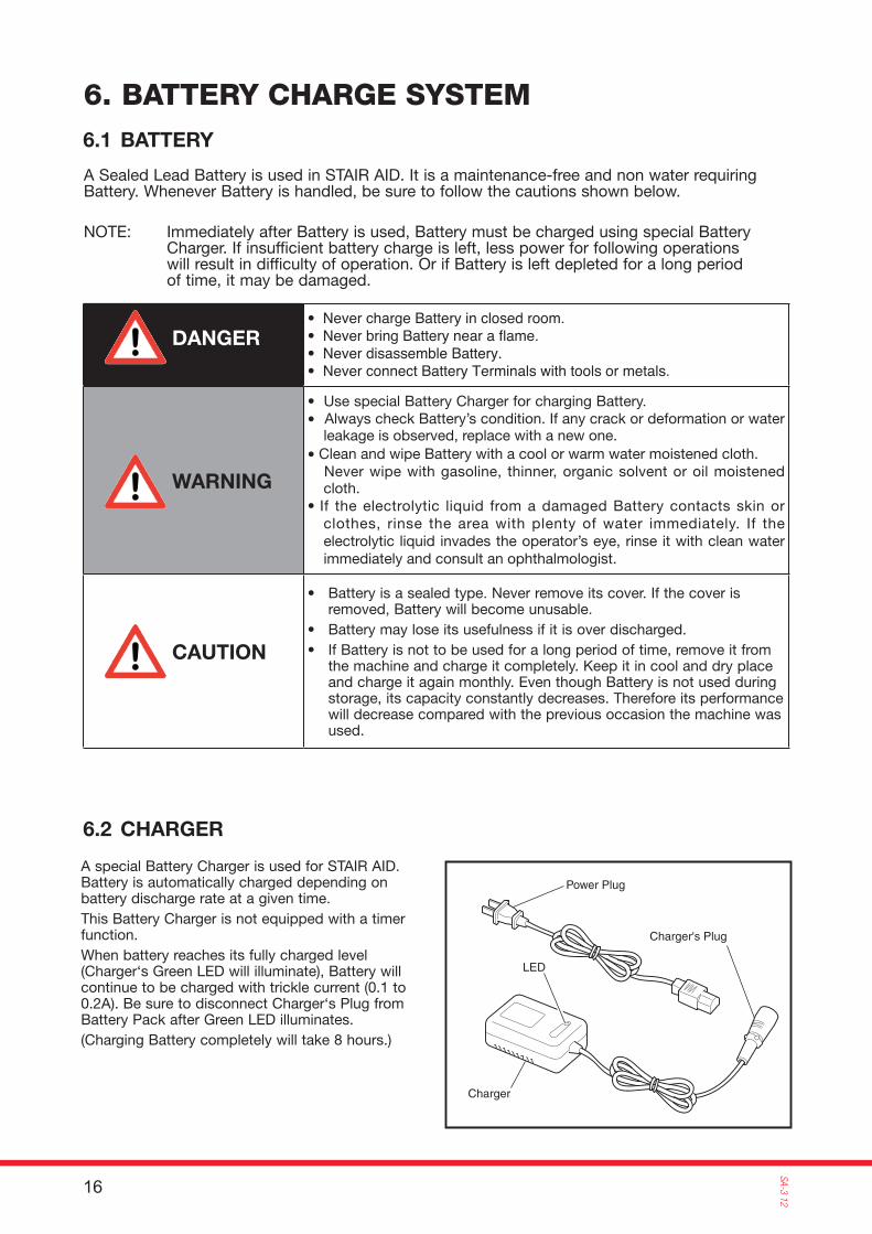
Charger's Plug
LED
Charger
Power Plug
6. BATTERY CHARGE SYSTEM6.1 BATTERY
A Sealed Lead Battery is used in STAIR AID. It is a maintenance-free and non water requiring Battery. Whenever Battery is handled, be sure to follow the cautions shown below.
NOTE: Immediately after Battery is used, Battery must be charged using special Battery Charger. If insufficient battery charge is left, less power for following operations will result in difficulty of operation. Or if Battery is left depleted for a long period of time, it may be damaged.
• Never charge Battery in closed room.• Never bring Battery near a � ame.• Never disassemble Battery. • Never connect Battery Terminals with tools or metals.
• Use special Battery Charger for charging Battery.• Always check Battery’s condition. If any crack or deformation or water
leakage is observed, replace with a new one.• Clean and wipe Battery with a cool or warm water moistened cloth.
Never wipe with gasoline, thinner, organic solvent or oil moistened cloth.
• If the electrolytic liquid from a damaged Battery contacts skin or clothes, rinse the area with plenty of water immediately. If the electrolytic liquid invades the operator’s eye, rinse it with clean water immediately and consult an ophthalmologist.
• Battery is a sealed type. Never remove its cover. If the cover is removed, Battery will become unusable.
• Battery may lose its usefulness if it is over discharged.• If Battery is not to be used for a long period of time, remove it from
the machine and charge it completely. Keep it in cool and dry place and charge it again monthly. Even though Battery is not used during storage, its capacity constantly decreases. Therefore its performance will decrease compared with the previous occasion the machine was used.
DANGER
WARNING
CAUTION
A special Battery Charger is used for STAIR AID. Battery is automatically charged depending on battery discharge rate at a given time. This Battery Charger is not equipped with a timer function. When battery reaches its fully charged level (Charger‘s Green LED will illuminate), Battery will continue to be charged with trickle current (0.1 to 0.2A). Be sure to disconnect Charger‘s Plug from Battery Pack after Green LED illuminates.(Charging Battery completely will take 8 hours.)
6.2 CHARGER
17
SA-3
12
100-240V AC outlet
Charger
Battery Pack
Please charge iton this side.
Charger's Plug
ReceptacleLid
OFF
ReceptacleLid
Charger's Plug
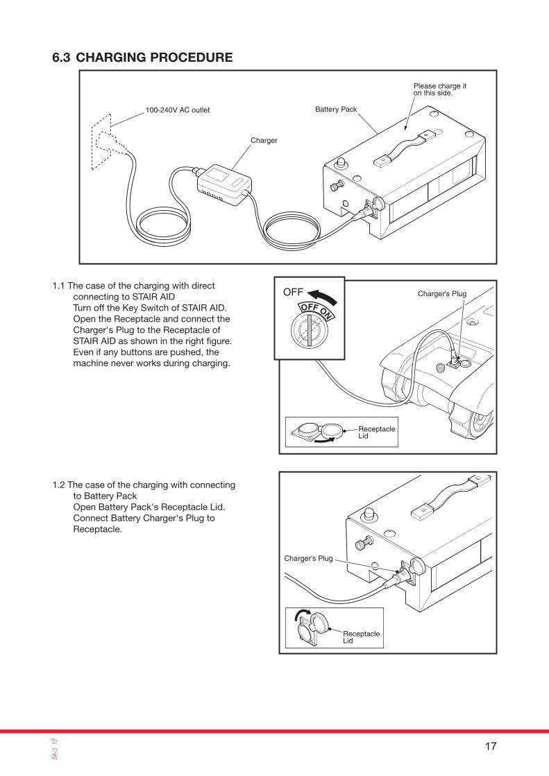
1.1 The case of the charging with direct connecting to STAIR AIDTurn off the Key Switch of STAIR AID.Open the Receptacle and connect the Charger's Plug to the Receptacle of STAIR AID as shown in the right fi gure.Even if any buttons are pushed, the machine never works during charging.
1.2 The case of the charging with connecting to Battery PackOpen Battery Pack's Receptacle Lid.Connect Battery Charger's Plug to Receptacle.
6.3 CHARGING PROCEDURE
18
SA-3 12
HIGH POWER TECH.
LED
Power Plug
100-240V AC outlet
AC Adapter
• This Charger is not equipped with a timer function. When Green LED illuminates, disconnect Charger‘s Plug from Battery Pack‘s Receptacle.
• Charge Battery in an ambient temperature between 5 and 40°C. If Battery is charged in an ambient temperature lower than 5°C, it may not charge fully.
CAUTION
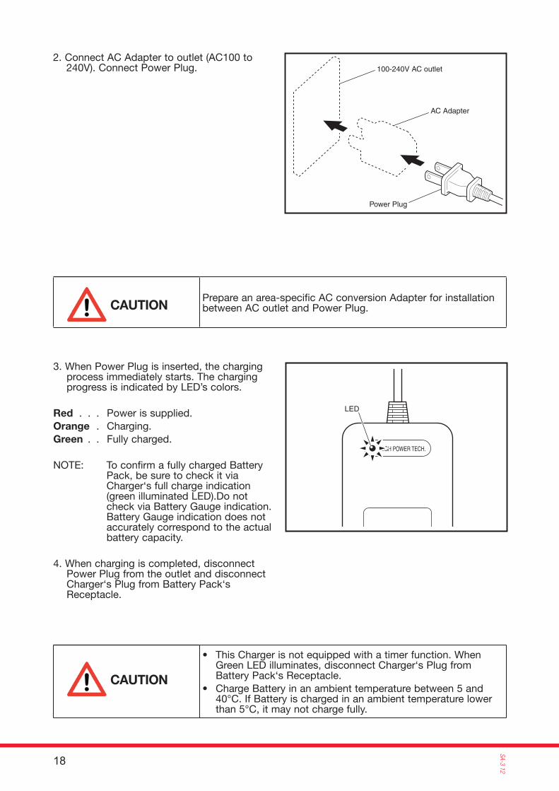
3. When Power Plug is inserted, the charging process immediately starts. The charging progress is indicated by LED’s colors.
Red . . . Power is supplied.Orange . Charging.Green . . Fully charged.
NOTE: To confirm a fully charged Battery Pack, be sure to check it via Charger‘s full charge indication (green illuminated LED).Do not check via Battery Gauge indication. Battery Gauge indication does not accurately correspond to the actual battery capacity.
4. When charging is completed, disconnect Power Plug from the outlet and disconnect Charger‘s Plug from Battery Pack‘s Receptacle.
Prepare an area-specific AC conversion Adapter for installation between AC outlet and Power Plug.CAUTION
2. Connect AC Adapter to outlet (AC100 to 240V). Connect Power Plug.
19
SA-3
12
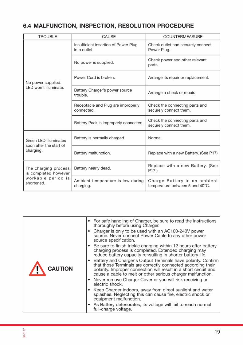
TROUBLE CAUSE COUNTERMEASURE
No power supplied.LED won’t illuminate.
Insuffi cient insertion of Power Plug into outlet.
Check outlet and securely connect Power Plug.
No power is supplied.Check power and other relevant parts.
Power Cord is broken. Arrange its repair or replacement.
Battery Charger’s power source trouble.
Arrange a check or repair.
Receptacle and Plug are improperly connected.
Check the connecting parts and securely connect them.
Battery Pack is improperly connected.Check the connecting parts and securely connect them.
Green LED illuminates soon after the start of charging.
Battery is normally charged. Normal.
Battery malfunction. Replace with a new Battery. (See P17)
The charging process is completed however wo rkab le pe r i od i s shortened.
Battery nearly dead.Replace with a new Battery. (See P17.)
Ambient temperature is low during charging.
Cha rge Ba t te ry i n an amb ien t temperature between 5 and 40°C.
• For safe handling of Charger, be sure to read the instructions thoroughly before using Charger.
• Charger is only to be used with an AC100-240V power source. Never connect Power Cable to any other power source specification.
• Be sure to finish trickle charging within 12 hours after battery charging process is completed. Extended charging may reduce battery capacity re¬sulting in shorter battery life.
• Battery and Charger‘s Output Terminals have polarity. Confirm that those Terminals are correctly connected according their polarity. Improper connection will result in a short circuit and cause a cable to melt or other serious charger malfunction.
• Never remove Charger Cover or you will risk receiving an electric shock.
• Keep Charger indoors, away from direct sunlight and water splashes. Neglecting this can cause fire, electric shock or equipment malfunction.
• As Battery deteriorates, its voltage will fail to reach normal full-charge voltage.
CAUTION
6.4 MALFUNCTION, INSPECTION, RESOLUTION PROCEDURE

20
SA-3 12
Battery
Screw
BatteryCase
Cover
Breaker
White
White
Black
Black
Black
BlackBlack
Red
Red
Red
Red
Battery Battery
Receptacle
FloatingConnector
6.5 BATTERY REPLACEMENT
1. Unscrew the screw mounting Battery Case and Cover.
2. Disconnect cables from Battery Terminals, remove exhausted Batteries, and install new ones.
3. Connect cables to Battery Terminals as shown in the figure below. Confirm that cables are properly connected to proper terminals. Then apply adhesive agent to Connectors to prevent their loosening.
While Key Switch is set to ON, power will be supplied from Battery. If STAIR AID is not be used, be sure to set Key to OFF and remove it from Key Switch.
CAUTION
21
SA-3
12
For safe operation of the Battery, read thoroughly the caution items described on the instruction manual and also read the following cautions.
1. Do not keep the Battery at a place where there may be a danger of fl ooding. Keeping the Battery in such places may cause leakage resulting in an electric shock or fi re.
2. Make sure the polarity terminals are connected correctly. Wrong terminal connection will cause excessive current resulting in fi re or damage to the machine.
3. Do not weld the Battery's terminal or charge the Battery by connecting cables with wrong polarity terminals. It may cause leakage of electrolytic solution, overheating or explosion.
4. Never use the Battery near heating places such as power transformers. Never use or keep the Battery in an automobile under a blazing sun, a place where direct sun beam reaches, near a stove, or anywhere a fi re may occur. The Battery temperature may rise resulting in leakage of electrolytic solution, overheating or explosion.
5. Never disassemble, remodel or destroy the Battery. Doing so may cause leakage of electrolytic solution, overheating or explosion.
6. Use the Special Battery Charger or keep the battery charged as specifi ed by the manufacturer. Charging with other charging condition may cause overheating of the Battery or discharge of hydrogen gas resulting in leakage of electrolytic solution, overheating or explosion.
7. The Battery contains diluted sulfuric acid. If diluted sulfuric acid adheres to skin or clothes due to leakage, rinse it immediately with water. If diluted sulfuric acid gets into your eyes, rinse it immediately with plenty of tap or clean water, then go see a doctor. Diluted sulfuric acid into the eye may cause loss of sight. Diluted sulfuric acid adhering to the skin may cause burn.
8. The operating temperature range of the Battery is shown below. Operation outside the operating temperature range reduces Battery performance and shortens its life, and furthermore it may cause leakage of electrolytic solution, overheating or explosion.
Discharge cycle: -15 to+50°C Charge cycle: 0 to +40°C Storage temperature: -15 to +40°C
9. Never use the Battery for anything other than as specifi ed. Usages other than the specifi ed purposes may cause leakage of electrolytic solution, overheating or explosion.
10. Excessive repeated overcharging may shortened the life of the Battery. Follow the specifi ed Battery charging condition.
Please cooperate in recycling the BatteryUsed Battery will be recycled. For Battery disposal, contact the sales agency or SUNWA Co., Ltd.When the Battery is returned, be sure to apply insulation tape to the Battery terminals. Used Battery still maintains charge. Battery terminal exposure may cause explosion or fi re.
6.6 HANDLING WARNINGS OF LEAD BATTERY
22
SA-3 12
Key Switch
DOWN Push Button (Red)
DOWN Lamp(DOWN Arrow Shaped Lamp)
Power Lamp
Emergency Stop SwitchBattery Gauge
UP Push Button (Green)
UP Lamp (UP Arrow Shaped Lamp)
[ Operation Switch Panel ]
Widthadjustment
Widthadjustment
Height adjustment
Stopper Pins
Stopper Pin
Slide Blocks
Confirm that the Stopper Pin is pressed by the spring force to the arrow direction shown in the figure.
Confirm that the Stopper Pin is pressed by the spring force to the arrow direction shown in the figure.
Seat Belt
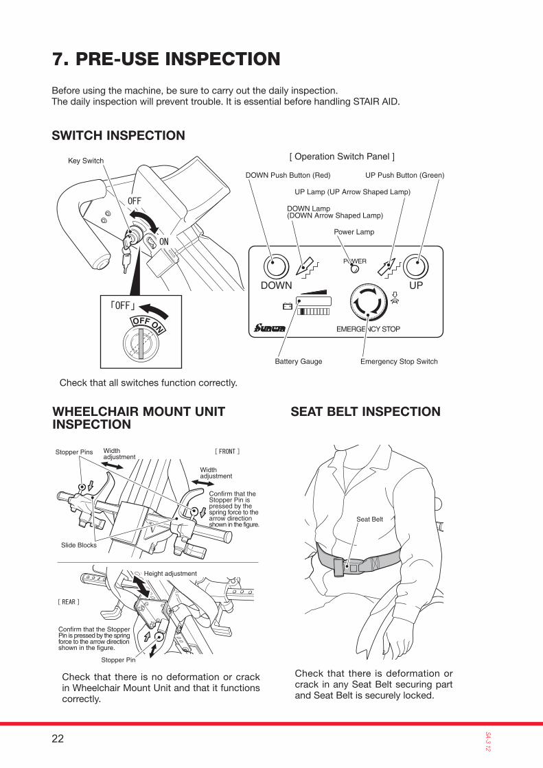
Before using the machine, be sure to carry out the daily inspection.The daily inspection will prevent trouble. It is essential before handling STAIR AID.
Check that all switches function correctly.
Check that there is no deformation or crack in Wheelchair Mount Unit and that it functions correctly.
Check that there is deformation or crack in any Seat Belt securing part and Seat Belt is securely locked.
7. PRE-USE INSPECTION
SWITCH INSPECTION
WHEELCHAIR MOUNT UNIT INSPECTION
SEAT BELT INSPECTION
23
SA-3
12
Control CablePedal Guard
Kick Bar
Handle Unit
Latch Keys
MotorReductionGear
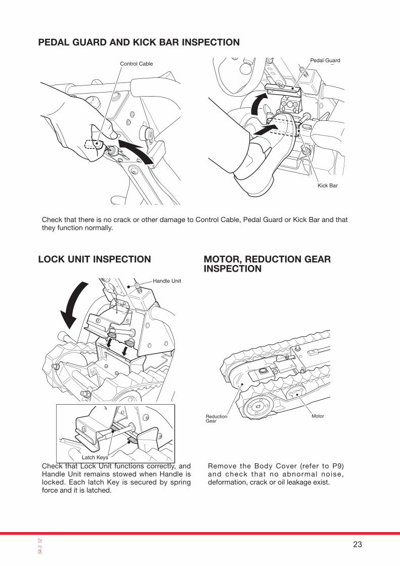
Check that there is no crack or other damage to Control Cable, Pedal Guard or Kick Bar and that they function normally.
Check that Lock Unit functions correctly, and Handle Unit remains stowed when Handle is locked. Each latch Key is secured by spring force and it is latched.
Remove the Body Cover (refer to P9) and check that no abnormal noise, deformation, crack or oil leakage exist.
PEDAL GUARD AND KICK BAR INSPECTION
LOCK UNIT INSPECTION MOTOR, REDUCTION GEAR INSPECTION
24
SA-3 12
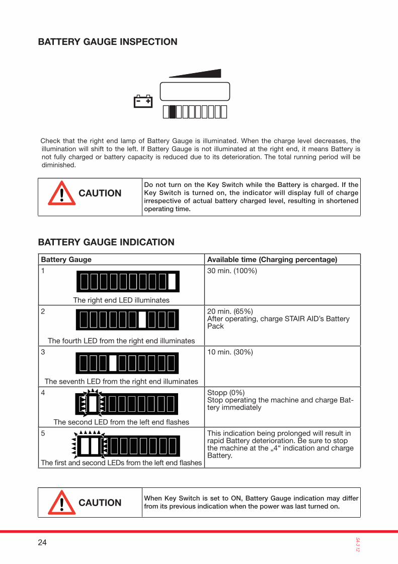
Check that the right end lamp of Battery Gauge is illuminated. When the charge level decreases, the illumination will shift to the left. If Battery Gauge is not illuminated at the right end, it means Battery is not fully charged or battery capacity is reduced due to its deterioration. The total running period will be diminished.
BATTERY GAUGE INSPECTION
Battery Gauge Available time (Charging percentage)
1
The right end LED illuminates
30 min. (100%)
2
The fourth LED from the right end illuminates
20 min. (65%)After operating, charge STAIR AID’s Battery Pack
3
The seventh LED from the right end illuminates
10 min. (30%)
4
The second LED from the left end fl ashes
Stopp (0%)Stop operating the machine and charge Bat-tery immediately
5
The fi rst and second LEDs from the left end fl ashes
This indication being prolonged will result in rapid Battery deterioration. Be sure to stop the machine at the „4“ indication and charge Battery.
BATTERY GAUGE INDICATION
When Key Switch is set to ON, Battery Gauge indication may differ from its previous indication when the power was last turned on.CAUTION
Do not turn on the Key Switch while the Battery is charged. If the Key Switch is turned on, the indicator will display full of charge irrespective of actual battery charged level, resulting in shortened operating time.
CAUTION

25
SA-3
12
Rubber Crawler
Slip Mark (The Slip Mark does not appear) Wheels
Check that there is no crack, wear or pitch error garding Rubber Crawlers. The pitch error can be confi rmed from Slip Mark deviation.
Check that no Screw has dropped out and that all Screws are tightly attached.
- Check that Wheels moves smoothly.- Check that no crack or damage exists in the Wheels.
RUBBER CRAWLER INSPECTION
SCREWS INSPECTION
WHEEL INSPECTION

26
SA-3 12
Key Switch
Check that the stair height, edge's roundness of the stairs, angle of the stairs, and the stairs pitch are within specifi cations by using the Stair Gauge.
1. Confi rm that Key Switch is set to “OFF”.
2. Set Wheelchair from the front of STAIR AID.
3. Adjust so that point A on the Wheelchair's handle and point B of STAIR AID are aligned vertically. And then set the Wheelchair's parking brake.
8. OPERATION
8.1 WHEELCHAIR SETTING
27
SA-3
12
Control Cable
Kick Bar
Pedal Guard
Raise Handle Unituntil it contactsWheelchair
Confirm that the Knob is locked.Heightadjustment
Locked
Released
Knob
Knob is locked
Knob is not locked
Slide Block
Widthadjustment
Stopper Pin
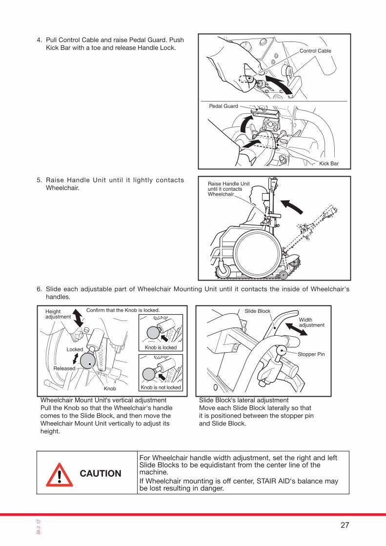
4. Pull Control Cable and raise Pedal Guard. Push Kick Bar with a toe and release Handle Lock.
5. Raise Handle Unit until it lightly contacts Wheelchair.
6. Slide each adjustable part of Wheelchair Mounting Unit until it contacts the inside of Wheelchair's handles.
Wheelchair Mount Unit's vertical adjustment Pull the Knob so that the Wheelchair's handle comes to the Slide Block, and then move the Wheelchair Mount Unit vertically to adjust its height.
Slide Block's lateral adjustmentMove each Slide Block laterally so that it is positioned between the stopper pin and Slide Block.
For Wheelchair handle width adjustment, set the right and left Slide Blocks to be equidistant from the center line of the machine.If Wheelchair mounting is off center, STAIR AID‘s balance may be lost resulting in danger.
CAUTION
28
SA-3 12
StopperPin
Fork
Wheelchair's handle
Stopper Pin
Fork
Set Fork while it is securely contacting tube
Seat Belt
Handle Unit
Guide Plate
Lock Pins
R Pins
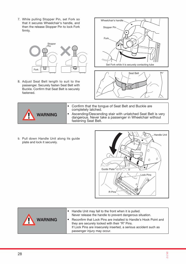
7. While pulling Stopper Pin, set Fork so that it secures Wheelchair's handle, and then the release Stopper Pin to lock Fork fi rmly.
8. Adjust Seat Belt length to suit to the passenger. Securely fasten Seat Belt with Buckle. Confi rm that Seat Belt is securely fastened.
9. Pull down Handle Unit along its guide plate and lock it securely.
• Confirm that the tongue of Seat Belt and Buckle are completely latched.
• Ascending/Descending stair with unlatched Seat Belt is very dangerous. Never take a passenger in Wheelchair without fastening Seat Belt.
WARNING
• Handle Unit may fall to the front when it is pulled.Never release the handle to prevent dangerous situation.
• Recon� rm that Lock Pins are installed to Handle’s Hook Point and they are securely locked with their “R” Pins.If Lock Pins are insecurely inserted, a serious accident such as passenger injury may occur.
WARNING

29
SA-3
12
Latch Keys
Wheel
Key SwitchON
10. Set Key Switch to ON.
NOTE: Check that Battery Gauge shows Battery Pack charged enough. (Refer to P21”Battery Gauge inspection”)Unless Handle Unit is fully locked, Battery Gauge will not illuminate.(STAIR AID will not run even when Button is pressed UP or DOWN.)Check that the two Latch Keys are fi rmly latched with the spring force.
11. To run STAIR AID on a flat floor surface, manually push/pull STAIR AID on its Wheels. Do not use its Rubber Crawlers. The operator must hold both Handle Grips and transfer Wheelchair using STAIR AID's Wheels while tilting STAIR AID to make its Wheels act the fulcrum.
If operator releases Handle while Wheelchair is set on STAIR AID, STAIR AID may topple. To prevent a serious accident, operator must never release his/ her hands from STAIR AID‘s Handle.
WARNING
30
SA-3 12
Seat BeltMountMagnet
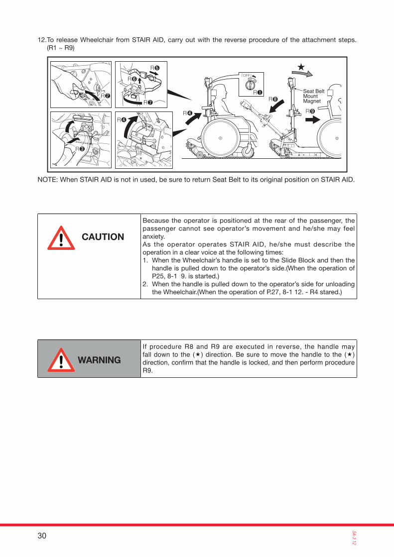
12. To release Wheelchair from STAIR AID, carry out with the reverse procedure of the attachment steps. (R1 ~ R9)
NOTE: When STAIR AID is not in used, be sure to return Seat Belt to its original position on STAIR AID.
If procedure R8 and R9 are executed in reverse, the handle may fall down to the (�) direction. Be sure to move the handle to the (�) direction, con� rm that the handle is locked, and then perform procedure R9.
WARNING
Because the operator is positioned at the rear of the passenger, the passenger cannot see operator’s movement and he/she may feel anxiety.As the operator operates STAIR AID, he/she must describe the operation in a clear voice at the following times:1. When the Wheelchair’s handle is set to the Slide Block and then the
handle is pulled down to the operator’s side.(When the operation of P25, 8-1 9. is started.)
2. When the handle is pulled down to the operator’s side for unloading the Wheelchair.(When the operation of P.27, 8-1 12. - R4 stared.)
CAUTION
31
SA-3
12
UPDOWN
EMERGENCY STOP
POWER
UP Push Button (Green)
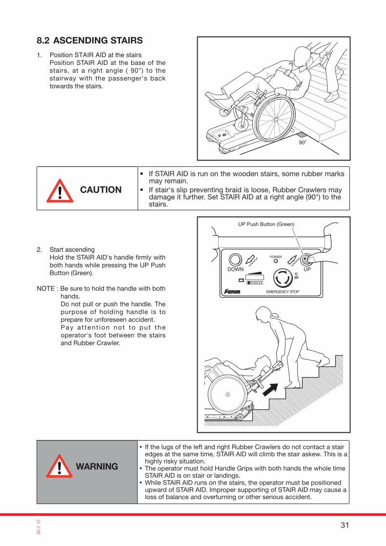
1. Position STAIR AID at the stairs Position STAIR AID at the base of the stairs, at a right angle ( 90°) to the stairway with the passenger's back towards the stairs.
2. Start ascending Hold the STAIR AID's handle fi rmly with both hands while pressing the UP Push Button (Green).
NOTE : Be sure to hold the handle with both hands.Do not pull or push the handle. The purpose of holding handle is to prepare for unforeseen accident.Pay a t ten t ion no t to pu t the operator's foot between the stairs and Rubber Crawler.
8.2 ASCENDING STAIRS
• If STAIR AID is run on the wooden stairs, some rubber marks may remain.
• If stair‘s slip preventing braid is loose, Rubber Crawlers may damage it further. Set STAIR AID at a right angle (90°) to the stairs.
CAUTION
• If the lugs of the left and right Rubber Crawlers do not contact a stair edges at the same time, STAIR AID will climb the stair askew. This is a highly risky situation.
• The operator must hold Handle Grips with both hands the whole time STAIR AID is on stair or landings.
• While STAIR AID runs on the stairs, the operator must be positioned upward of STAIR AID. Improper supporting of STAIR AID may cause a loss of balance and overturning or other serious accident.
WARNING
32
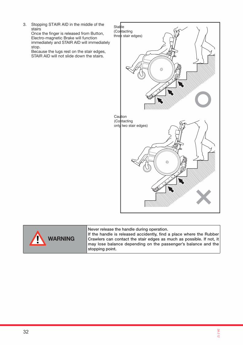
SA-3 123. Stopping STAIR AID in the middle of the
stairs Once the fi nger is released from Button, Electro-magnetic Brake will function immediately and STAIR AID will immediately stop.Because the lugs rest on the stair edges, STAIR AID will not slide down the stairs.
Stable (Contacting three stair edges)
Caution(Contacting only two stair edges)
Never release the handle during operation.If the handle is released accidently, find a place where the Rubber Crawlers can contact the stair edges as much as possible. If not, it may lose balance depending on the passenger’s balance and the stopping point.
WARNING
33
SA-3
12
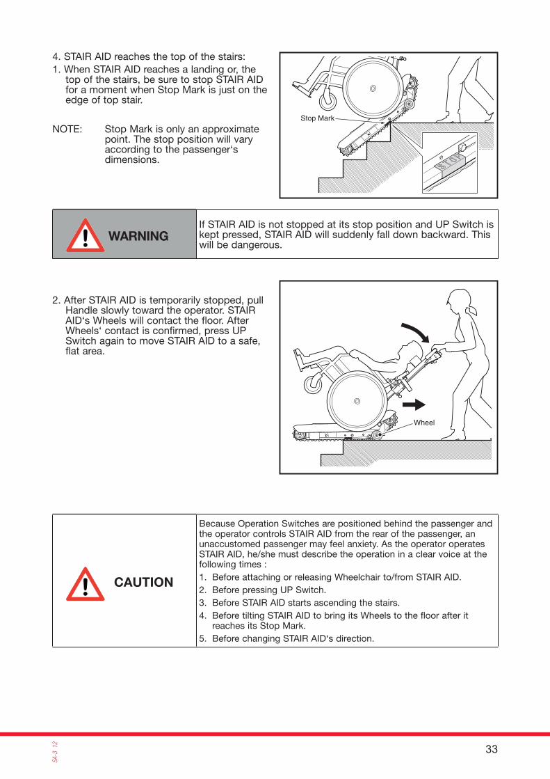
Stop Mark
Wheel
4. STAIR AID reaches the top of the stairs:1. When STAIR AID reaches a landing or, the
top of the stairs, be sure to stop STAIR AID for a moment when Stop Mark is just on the edge of top stair.
NOTE: Stop Mark is only an approximate point. The stop position will vary according to the passenger‘s dimensions.
If STAIR AID is not stopped at its stop position and UP Switch is kept pressed, STAIR AID will suddenly fall down backward. This will be dangerous.
WARNING
2. After STAIR AID is temporarily stopped, pull Handle slowly toward the operator. STAIR AID‘s Wheels will contact the floor. After Wheels‘ contact is confirmed, press UP Switch again to move STAIR AID to a safe, flat area.
Because Operation Switches are positioned behind the passenger and the operator controls STAIR AID from the rear of the passenger, an unaccustomed passenger may feel anxiety. As the operator operates STAIR AID, he/she must describe the operation in a clear voice at the following times :1. Before attaching or releasing Wheelchair to/from STAIR AID.2. Before pressing UP Switch.3. Before STAIR AID starts ascending the stairs.4. Before tilting STAIR AID to bring its Wheels to the floor after it
reaches its Stop Mark.5. Before changing STAIR AID‘s direction.
CAUTION
34
SA-3 12
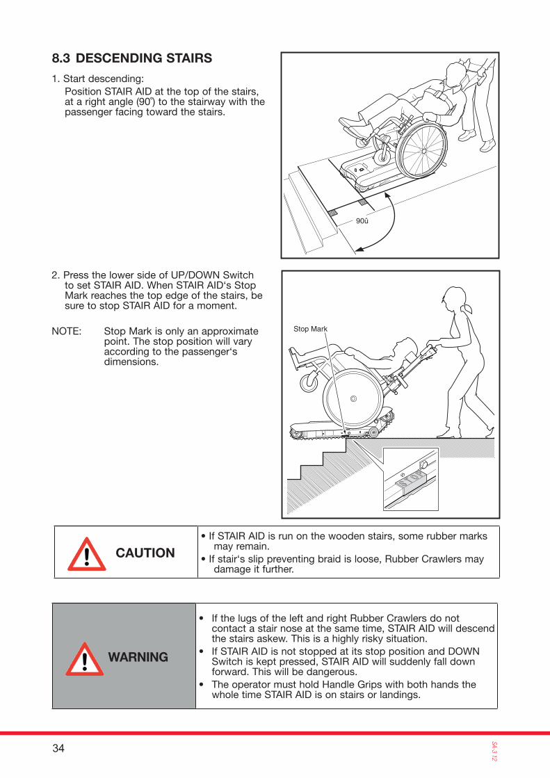
Stop Mark
90û
8.3 DESCENDING STAIRS
1. Start descending: Position STAIR AID at the top of the stairs,
at a right angle (90˚) to the stairway with the passenger facing toward the stairs.
2. Press the lower side of UP/DOWN Switch to set STAIR AID. When STAIR AID‘s Stop Mark reaches the top edge of the stairs, be sure to stop STAIR AID for a moment.
NOTE: Stop Mark is only an approximate point. The stop position will vary according to the passenger‘s dimensions.
• If STAIR AID is run on the wooden stairs, some rubber marks may remain.
• If stair‘s slip preventing braid is loose, Rubber Crawlers may damage it further.
CAUTION
• If the lugs of the left and right Rubber Crawlers do not contact a stair nose at the same time, STAIR AID will descend the stairs askew. This is a highly risky situation.
• If STAIR AID is not stopped at its stop position and DOWN Switch is kept pressed, STAIR AID will suddenly fall down forward. This will be dangerous.
• The operator must hold Handle Grips with both hands the whole time STAIR AID is on stairs or landings.
WARNING

35
SA-3
12
UPDOWN
EMERGENCY STOP
POWER
DOWN Push Button (Red)
Second stair
Stop Mark
3. S lowly push hand le unt i l Rubber Crawlers contact the second stair while keeping STAIR AID balanced at the same position.
4. When Rubber Crawlers contact the lower stair and STAIR AID becomes stable, press DOWN Push Button(Red).
Because Operation Switches are positioned behind the pas-senger and the operator controls STAIR AID from the rear of the passenger, an unaccustomed passenger may feel anxiety. As the operator operates STAIR AID, he/she must describe the operati-on in a clear voice at the following times :1. Before attaching or releasing Wheelchair to/from STAIR AID.2. Before pressing DOWN Switch.3. Before STAIR AID starts descending the stairs.4. Before tilting STAIR AID to bring its Wheels to the floor after it
reaches its Stop Mark.5. Before changing STAIR AID‘s direction.
CAUTION
While STAIR AID runs on the stairs, the operator must be posi-tioned upward of STAIR AID. Improper supporting of STAIR AID may cause a loss of balance and overturning or other serious accident.
WARNING
5. STAIR AID reaches the bottom of the stairs Keep pressing DOWN Switch until STAIR AID reaches the bottom of the stairs. STAIR AID will automatically transfer to horizontal running. Release DOWN Switch and Wheel STAIR AID to a safe area.
36
SA-3 12
9.1 BATTERY
9. DAILY MAINTENANCE AND CARE
• When STAIR AID is not to be used or its Battery Pack is to be charged, turn off Key Switch and remove Key. If Key Switch is kept in the ON position, Battery will quickly discharge and it may not have capacity to run STAIR AID the following day.
• After the end of operation or before storing it, be sure to charge Battery using special Charger. (Because it requires a long charging time, if it is not charged enough, it will be difficult to operate the following day.)
• When storing STAIR AID for a long period of time, maintain its Battery in a fully charged state. Not doing so will result in an extremely short life. (Even if Battery is already fully charged, recharge Battery again monthly.)
9.2 RUBBER CRAWLERS
• If oil adheres, immediately wipe it off completely.• Check there is no crack or wear concerning Rubber Crawlers. If any defect on Rubber
Crawler is observed, stop STAIR AID immediately and replace the part with a new one.
9.3 STORAGE OF STAIR AID
• If STAIR AID is stored for a long period of the time, turn the Rubber Crawlers once per month to avoid the Rubber Crawler from having a permanent bending deformation.
The activated guarantee is for a period of five years, apart from batteries and rubber parts. It is limited to complaint parts free of charge excluding freight, cost for labor or travelling expenses.
We suggest to make maintenance once a year by authorized agent to avoid guarantee obliga-tions.
10. TERMS OF GUARANTEE
37
SA-3
12
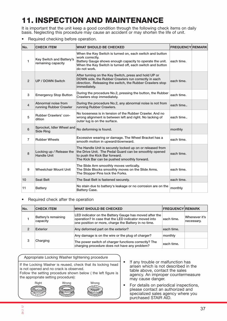
Right Wrong Wrong
If the Locking Washer is reused, check that its locking head is not opened and no crack is observed.Follow the setting procedure shown below ( the left fi gure is the appropriate setting procedure):
Appropriate Locking Washer tightening procedure
11. INSPECTION AND MAINTENANCE
• !f any trouble or malfunction has arisen which is not described in the table above, contact the sales agency. An improper countermeasure may cause danger.
• For details on periodical inspections, please contact an authorized and specialized sales agency where you purchased STAIR AID.
It is important that the unit keep a good condition through the following check items on daily basis. Neglecting this procedure may cause an accident or may shorten the life of unit.
No. CHECK ITEM WHAT SHOULD BE CHECKED FREQUENCY REMARK
1 Key Switch and Battery’s remaining capacity
When the Key Switch is turned on, each switch and button work correctly.Battery Gauge shows enough capacity to operate the unit. When the Key Switch is turned off, each switch and button do not work.
each time.
2 UP / DOWN Switch
After turning on the Key Switch, press and hold UP or DOWN side, the Rubber Crawlers run correctly in each direction. Releasing the switch, the Rubber Crawlers stop immediately.
each time.
3 Emergency Stop Button During the procedure No.2, pressing the button, the Rubber Crawlers stop immediately. each time.
4 Abnormal noise from running Rubber Crawler
During the procedure No.2, any abnormal noise is not from running Rubber Crawlers. each time..
5 Rubber Crawlers’ con-dition
No looseness is in tension of the Rubber Crawler. And no wrong alignment is between left and right. No lacking of outer lug is on the surface.
each time..
6 Sprocket, Idler Wheel and Side Ring No deforming is found. monthly
7 Rubber Wheels Excessive wearing or damage. The Wheel Bracket has a smooth motion in upward/downward. each time.
8 Locking up / Release the Handle Unit
The Handle Unit is securely locked up on or released from the Drive Unit. The Pedal Guard can be smoothly opened to push the Kick Bar forward.The Kick Bar can be pushed smoothly forward.
each time.
9 Wheelchair Mount UnitThe Slide Arm smoothly moves vertically.The Slide Blocks smoothly moves on the Slide Arms.The Stopper Pins lock the Forks.
each time.
10 Seat Belt The Seat Belt is fastened securely. each time.
11 Battery No stain due to battery‘s leakage or no corrosion are on the Battery Case. monthly
• Required checking before operation.
No. CHECK ITEM WHAT SHOULD BE CHECKED FREQUENCY REMARK
1 Battery’s remaining capacity
LED indicator on the Battery Gauge has moved after the operation? In case that the LED indicator moved into one position or more, charge the Battery in no time.
each time. Whenever it’s necessary.
2 Exterior Any deformed part on the exterior? each time.
3 Charging
Any damage is on the wire or the plug of charger? monthly
The power switch of charger functions correctly? The charging procedure does not have any problem? each time.
• Required check after the operation