
STAINLESS STEEL PRESSURE RATED TAPPING …2017-4-10 · “The Standard of Excellence in the...
12
“The Standard of Excellence in the Industry” PATENTED CERTIFIED TO NSF/ANSI 61 STAINLESS STEEL PRESSURE RATED TAPPING SLEEVE STYLE CST-EX STYLE CST-SL © 2016 Cascade Waterworks Mfg. 1213 BADGER STREET • YORKVILLE, ILLINOIS 60560 (630) 553-0840 • (800) 426-4301 • FAX (630) 553-0181 www.cascademfg.com
Transcript of STAINLESS STEEL PRESSURE RATED TAPPING …2017-4-10 · “The Standard of Excellence in the...

“The Standard
of Excellence in
the Industry”
PATENTEDCERTIFIED TO NSF/ANSI 61
STAINLESS STEEL
PRESSURE RATEDTAPPING SLEEVE
STYLECST-EX
STYLECST-SL
© 2016 Cascade Waterworks Mfg.
1213 BADGER STREET • YORKVILLE, ILLINOIS 60560(630) 553-0840 • (800) 426-4301 • FAX (630) 553-0181www.cascademfg.com

2
STYLE CST-EX
• Drop-in Bolts with Heavy-duty Lugs• Easy to install — lighter and fewer parts than mechanical joint iron tapping sleeves• All branch sections double welded to both shell and flange – TIG inside/MIG outside• All weldments fully chemically passivated in accordance with ASTM A380.• Full hoop support and double o-ring branch seal• Each sleeve hydrostatically tested to 1.5 times R.W.P. at factory• Each sleeve serial numbered – certified test records available• All sleeves provided with test outlet• Branch I.D. 0.5” larger than nominal size• Accepts full size shell cutter (except size-on-size)• Broad range of options: — Stainless steel or low alloy steel flanges — Special steels - T304L, T316 or T316L (available upon request)• Special application pressure ratings available • Ten Year Warranty
CST-EX INFORMATION
• ThroatGasket(USPATENT6,173,967B1)-DoubleO-Ringforhighpressuresealingwithhydrauliclipandstainlesssteelringinsertmoldedinsidetopreventradialexpansionunderpressure.TwinO-Ringonbacksideofgasketforhighpressureprotection.

3
STYLE CST-SL
• Lighter Option with Stud and Receiver Bar assemblies• Easy to install — lighter and fewer parts than mechanical joint iron tapping sleeves• All branch sections double welded to both shell and flange – TIG inside/MIG outside• All weldments fully chemically passivated in accordance with ASTM A380. • Full hoop support and double o-ring branch seal • Each sleeve hydrostatically tested to 1.5 times R.W.P. at factory • Each sleeve serial numbered – certified test records available • All sleeves provided with test outlet • Branch I.D. 0.5” larger than nominal size • Accepts full size shell cutter (except size-on-size) • Broad range of options: — Stainless steel or low alloy steel flanges — Special steels – T304L, T316 or T316L (available upon request) • Special application pressure ratings available • Ten Year Warranty
CST-SL INFORMATION
US PATENT6,173,967 B1
• Matgasketcompletesfullhoopsupportonmainpipe.
• Gasketdetail-viewshowinggasketnotcompressed

4
STYLE CST-EX
For higher pressures or special requirements, consult factory. Tapping Sleeve shall meet or exceed AWWA C223.
INSTALLATION INSTRUCTIONS
snoisnemiDhcnarB Number of Test PressureSize A B C D E Bolts (psi) min.
3 7.5" 12" 3.75" 3.5" .50" 8 2254 9" 15" 3.75" 4.5" .62" 10 2256 11" 15" 4.25" 6.5" .68" 10 2258 13.5" 21" 4.75" 8.5" .68" 14 22510 16" 30" 5.25" 10.5" .68" 20 15012 19" 30" 6.25" 12.5" .81" 20 150
Number ofBolts
81010142020
1. Verify pipe O.D. and sleeve range, to ensure proper sleeve is being installed.2. Thoroughly clean all gaskets and entire pipe surface to be covered by sleeve. Lubricate both the sleeve gaskets and pipe surface with suitable pipe lubricant.
LUBRICATE GASKETS THOROUGHLY3. Position the tapping sleeve with outlet in the direction of branch pipe, with the Test Outlet facing up. Block the pipe on both sides of tap area to support during operation. Block Outlet area to support during valve connection.4. While installing the tapping sleeve, make sure the flaps are extended fully around pipe. Do not rotate tapping sleeve on pipe. (This may cause the gasket to roll.)5. Insert a bolt through centermost bolt hole on the top side. Place a nut & washer on the bolt and run the nut down until flush with end of bolt.6. Insert second bolt directly across from the first bolt on the bottom side. Place nut & washer on the bolt & run both nuts down (top & bottom sides) until they are Finger Tight. Make sure that the gap between shells on both top and bottom are approximately the same.7. Level the sleeve to it’s final position on main pipe. Adjust blocking as needed.8. Install remaining bolts, washers and nuts and tighten until Finger Tight.9. Inspect gaskets to verify that they have not rolled or distorted during steps 1) thru 8). A rolled gasket will create a leak path.10. Snug nuts down, working from top to bottom, and from the center outward, making sure the top gap and the bottom gap stays even.
MAINTAIN EVEN GAP BETWEEN SHELLS11. Tighten nuts to final torque.
Correct torque indicated by use of torque wrench.12. After final checking of bolt torque on both the sleeve and valve connections, you must use the 3/4” test port to pressurize sleeve and check seals. Re-torque nuts as necessary.
NOTE: FAILURE TO TEST ALL SEALS PRIOR TO TAP VOIDS ALL WARRANTIES.SIZE-ON-SIZE TAPPING SLEEVES REQUIRE ½” UNDERSIZE SHELL CUTTER.
Nominal Pipe Size Min. Torque Max. Torque
4 – 8 75 ft.-lbs. 120 ft.-lbs.
10 – 24 100 ft.-lbs. 150 ft.-lbs.
Notlisted ConsultFactory

5
rebmuNgolataClanimoNPipe Size Sleeve By Outlet
4.40 - 4.60 CST - EX - 460 X4.70 - 4.90 CST - EX - 490 X
4 4.80 - 5.00 CST - EX - 500 X 4* 5.10 - 5.30 CST - EX - 530 X5.20 - 5.40 CST - EX - 540 X6.60 - 7.00 CST - EX - 700 X6.90 - 7.30 CST - EX - 730 X 4
6 7.10 - 7.50 CST - EX - 750 X 6* 7.50 - 7.90 CST - EX - 790 X7.90 - 8.30 CST - EX - 830 X8.35 - 8.75 CST - EX - 875 X 4
8 8.63 - 9.05 CST - EX - 905 X 6 8.95 - 9.35 CST - EX - 935 X 8* 9.20 - 9.60 CST - EX - 960 X
10.50 - 10.90 CST - EX - 1090 X10.75 - 11.10 CST - EX - 1110 X 4
10 11.00 - 11.40 CST - EX - 1140 X 611.40 - 11.80 CST - EX - 1180 X 811.80 - 12.20 CST - EX - 1220 X 10*12.50 - 12.90 CST - EX - 1290 X 413.00 - 13.40 CST - EX - 1340 X 6
12 13.20 - 13.60 CST - EX - 1360 X 813.40 - 13.80 CST - EX - 1380 X 1014.00 - 14.40 CST - EX - 1440 X 12*
415.10 - 15.50 CST - EX - 1550 X 614 15.40 - 15.80 CST - EX - 1580 X 815.80 - 16.20 CST - EX - 1620 X 1016.38 - 16.78 CST - EX - 1678 X 12
17.20 - 17.60 CST - EX - 1760 X 417.40 - 17.80 CST - EX - 1780 X 6
16 17.76 - 18.16 CST - EX - 1816 X 818.40 - 18.80 CST - EX - 1880 X 1018.60 - 19.00 CST - EX - 1900 X 12
418.80 - 19.20 CST - EX - 1920 X 618 19.30 - 19.70 CST - EX - 1970 X 819.80 - 20.20 CST - EX - 2020 X 1021.00 - 21.40 CST - EX - 2140 X 12
421.40 - 21.80 CST - EX - 2180 X 6
20 21.90 - 22.30 CST - EX - 2230 X 822.10 - 22.50 CST - EX - 2250 X 10
12423.20 - 23.60 CST - EX - 2360 X 6
24 25.60 - 26.00 CST - EX - 2600 X 826.10 - 26.50 CST - EX - 2650 X 1027.90 - 28.30 CST - EX - 2830 X 12
O.D. Range(Inches)
STYLE CST-EX
AWWA C223 & NSF/ANSI 61 CompliantMATERIAL SPECIFICATIONS
Flange: T304 SST (AWWA C228), Low Alloy (AWWA C207)Fasteners: T304 SST; 5/8 UNC; Bolts - Rolled Thread; Nuts - Heavy Hex, Fluoropolymer CoatedLubricating Washers: Nylon
Bearing Washers/WasherPlates: T304 SST Shell/Lugs: T304 SSTGaskets: Virgin SBR (EDPM available upon request) Branch Gasket Patent 6,173,967B1
*Indicatessize-on-sizesleeveswithinthisrangerequirea1/2”undersizecutter.100%hydrostaticallytestedtoaminimumof1.5timesratedworkingpressure.Pressurecapacitymaybeapplicationsensitive.Larger Sizes, Special Ranges, and 3” Flange Outlets Available.Consultfactoryforspecificapplications.BranchSizes3”-8”:225psiMinimumTestPressure;BranchSizes10”-12”:150psiMinimumTestPressure.To Order:ChooseStyleofSleeve,O.D.RangeandOutletsize.Examples:Anextraheavy-dutysleevewitha6”Stainlessflangefor12”D.I.P.wouldbeCST-EX-1340-6-SS.Samesleevewitha6”LowAlloyflangewouldbeCST-EX-1340-6-LA.
STAINLESS STEEL TAPPING SLEEVE WITHSTAINLESS STEEL OR LOW ALLOY FLANGE
6
STYLE CST-SL
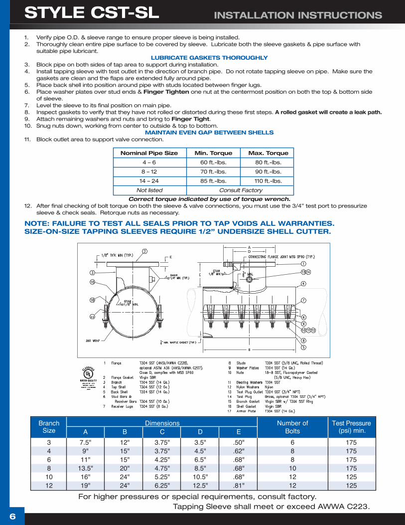
For higher pressures or special requirements, consult factory. Tapping Sleeve shall meet or exceed AWWA C223.
INSTALLATION INSTRUCTIONS
snoisnemiDhcnarB Test PressureSize A B C D E (psi) min.
3 7.5" 12" 3.75" 3.5" .50" 1754 9" 15" 3.75" 4.5" .62" 1756 11" 15" 4.25" 6.5" .68" 1758 13.5" 20" 4.75" 8.5" .68" 17510 16" 24" 5.25" 10.5" .68" 12512 19" 24" 6.25" 12.5" .81" 125
Number ofBolts
688101212
1. Verify pipe O.D. & sleeve range to ensure proper sleeve is being installed.2. Thoroughly clean entire pipe surface to be covered by sleeve. Lubricate both the sleeve gaskets & pipe surface with suitable pipe lubricant.
LUBRICATE GASKETS THOROUGHLY3. Block pipe on both sides of tap area to support during installation.4. Install tapping sleeve with test outlet in the direction of branch pipe. Do not rotate tapping sleeve on pipe. Make sure the gaskets are clean and the flaps are extended fully around pipe.5. Place back shell into position around pipe with studs located between finger lugs.6. Place washer plates over stud ends & Finger Tighten one nut at the centermost position on both the top & bottom side of sleeve.7. Level the sleeve to its final position on main pipe.8. Inspect gaskets to verify that they have not rolled or distorted during these first steps. A rolled gasket will create a leak path.9. Attach remaining washers and nuts and bring to Finger Tight.10. Snug nuts down, working from center to outside & top to bottom.
MAINTAIN EVEN GAP BETWEEN SHELLS11. Block outlet area to support valve connection.
Correct torque indicated by use of torque wrench.12. After final checking of bolt torque on both the sleeve & valve connections, you must use the 3/4” test port to pressurize sleeve & check seals. Retorque nuts as necessary.
NOTE: FAILURE TO TEST ALL SEALS PRIOR TO TAP VOIDS ALL WARRANTIES.SIZE-ON-SIZE TAPPING SLEEVES REQUIRE 1/2” UNDERSIZE SHELL CUTTER.
Nominal Pipe Size Min. Torque Max. Torque
4 – 6 60 ft.-lbs. 80 ft.-lbs.
8 – 12 70 ft.-lbs. 90 ft.-lbs.
14 – 24 85 ft.-lbs. 110 ft.-lbs.
Notlisted ConsultFactory

rebmuNgolataClanimoNPipe Size Sleeve By Outlet
O.D. Range(Inches)
4.40 - 4.60 CST - SL - 460 X4.70 - 4.90 CST - SL - 490 X
4 4.80 - 5.00 CST - SL - 500 X 4*5.10 - 5.30 CST - SL - 530 X5.20 - 5.40 CST - SL - 540 X6.60 - 7.00 CST - SL - 700 X6.90 - 7.30 CST - SL - 730 X 46 7.10 - 7.50 CST - SL - 750 X 6*7.50 - 7.90 CST - SL - 790 X7.90 - 8.30 CST - SL - 830 X8.35 - 8.75 CST - SL - 875 X 4
8 8.63 - 9.05 CST - SL - 905 X 68.95 - 9.35 CST - SL - 935 X 8*9.20 - 9.60 CST - SL - 960 X
10.50 - 10.90 CST - SL - 1090 X10.75 - 11.10 CST - SL - 1110 X 4
10 11.00 - 11.40 CST - SL - 1140 X 611.40 - 11.80 CST - SL - 1180 X 811.80 - 12.20 CST - SL - 1220 X 10*12.50 - 12.90 CST - SL - 1290 X 413.00 - 13.40 CST - SL - 1340 X 6
12 13.20 - 13.60 CST - SL - 1360 X 813.40 - 13.80 CST - SL - 1380 X 1014.00 - 14.40 CST - SL - 1440 X 12*
415.10 - 15.50 CST - SL - 1550 X 614 15.40 - 15.80 CST - SL - 1580 X 815.80 - 16.20 CST - SL - 1620 X 1016.38 - 16.78 CST - SL - 1678 X 12
17.20 - 17.60 CST - SL - 1760 X 417.40 - 17.80 CST - SL - 1780 X 6
16 17.76 - 18.16 CST - SL - 1816 X 818.40 - 18.80 CST - SL - 1880 X 1018.60 - 19.00 CST - SL - 1900 X 12
418.80 - 19.20 CST - SL - 1920 X 618 19.30 - 19.70 CST - SL - 1970 X 819.80 - 20.20 CST - SL - 2020 X 1021.00 - 21.40 CST - SL - 2140 X 12
421.40 - 21.80 CST - SL - 2180 X 6
20 21.90 - 22.30 CST - SL - 2230 X 822.10 - 22.50 CST - SL - 2250 X 10
12423.20 - 23.60 CST - SL - 2360 X 6
24 25.60 - 26.00 CST - SL - 2600 X 826.10 - 26.50 CST - SL - 2650 X 1027.90 - 28.30 CST - SL - 2830 X 12
Flange: T304 SST, Low AlloyAWWA C228Fasteners: T304 SST 5/8-11 UNC RolledThread; Heavy Hex Nut Xylan CoatedBearing Washers/WasherPlates: T304 SST
Lubricating Washers: NylonShell/Lugs: T304 SSTGaskets: Virgin SBR (Other com-pounds available upon request)Branch Gasket Patent 6,173,967B1
MATERIAL SPECIFICATIONS
STYLE CST-SL STAINLESS STEEL TAPPING SLEEVE WITHSTAINLESS STEEL OR LOW ALLOY FLANGESTYLE CST-SL
*Indicatessize-on-sizesleeveswithinthisrangerequirea1/2”undersizecutter.100%hydrostaticallytestedtoaminimumof1.5timesratedworkingpressure.Pressurecapacitymaybeapplicationsensitive.Larger Sizes, Special Ranges, and 3” Flange Outlets Available.Consultfactoryforspecificapplications.BranchSizes3”-8”:175psiMinimumTestPressure;BranchSizes10”-12”:125psiMinimumTestPressure.To Order:ChooseStyleofSleeve,O.D.RangeandOutletsize.Examples:Asuperlightweightsleevewitha6”Stainlessflangefor12”D.I.P.wouldbeCST-SL-1340-6-SS.Samesleevewitha6”LowAlloyflangewouldbeCST-SL-1340-6-LA.
7
STAINLESS STEEL TAPPING SLEEVE WITHSTAINLESS STEEL OR LOW ALLOY FLANGE
MATERIAL SPECIFICATIONS
Flange: T304 SST (AWWA C228), Low Alloy (AWWA C207)Fasteners: T304 SST; 5/8 UNC; Bolts - Rolled Thread; Nuts - Heavy Hex, Fluoropolymer CoatedLubricating Washers: Nylon
Bearing Washers/WasherPlates: T304 SST Shell/Lugs: T304 SSTGaskets: Virgin SBR (Other com-pounds available upon request)
AWWA C223 & NSF/ANSI 61 Compliant
8
SAMPLE SPECIFICATIONS - CST-EX
COMPLIES WITH AWWA C223
Tapping Sleeves shall be made from T304 stainless steel and shall conform in all respects to the following:
1. Flange: Shall be T304 SST in accordance with ANSI/AWWA C228 (optional Low Alloy in accordance with ANSI/AWWA C207), Class D with recessed I.D. to accept tapping valves.
2. Flange Gasket: Shall be Virgin SBR full face type and shall be attached to flange with contact cement.3. Branch: Shall be T304 SST 14 ga. rolled to size. The branch shall be TIG welded (GTAW) to the flange
and the top shell on the inside and MIG welded (GMAW) to the flange and top shell on the outside.
4. Top Shell: Shall be T304 SST 11 ga. minimum, rolled to size.5. Back Shell: Shall be T304 SST 14 ga. minimum, rolled to size.6. Bolt Lugs: Shall be T304 SST 7 ga. formed in a triangular section to provide bearing surface for track head
bolts. Lugs shall be MIG welded (GMAW) to shells at all contact points.7. Bolts: Shall be T304 / 18-8 SST 5/8 UNC track head, rolled thread.8. Nuts: Shall be T304 SST 5/8 UNC heavy hex. Nuts shall be coated with a Fluoropolymer Coating
to prevent galling during tightening.9. Bearing Washers: Shall be T304/18-8 SST 5/8". Washers shall be placed under each nut to
provide additional bearing surface.10. Test Plug Outlet: Shall be T304 SST, 3/4" NPT. Outlet shall be MIG welded (GMAW) to Branch.11. Test Plug: Shall be 3/4" NPT Brass (optional T304 SST). Plug shall have Teflon tape on threads to assist
sealing and prevent galling.12. Branch Gasket: Shall be Virgin SBR with double O-Ring and hydraulic lip. Gasket shall have T304 SST ring
insert molded within to prevent radial expansion under pressure. Gasket shall have twin O-Ringseals on backside for protection.
13. Shell Gaskets: Shall be Virgin SBR with 1/4" grid pattern and tapered ends to provide a complete 360 degreeswrap around the main pipe. Section of shell gasket that bridges gap between shells shall have aT304 SST armor.
15. Welds: All welds shall be free from pinholes and other defects and shall be fully chemically passivatedin accordance with ASTM A380.
extend the entire length of the sleeve. Armor to be TIG welded (GTAW) to branch shell.
16. Testing: All sleeves shall be provided (if requested) with a certification that they have been tested to 1.5times the rated working pressure, and have passed, at the factory. Each sleeve shall have apredominate marking to designate the test.
17. Markings: Each sleeve shall bear indelible markings indicating1) Manufacturerʼs Name2) Part Number3) Date of Manufacture4) Serial Number – Metal Stamp on Edge of Flange5) Rated Working Pressure6) Test Pressure7) Certified to NSF/ANSI 618) U/L Stamp Approval for Materials
18. InstallationInstructions: Each sleeve shall have installation instructions attached.
19. Warranty: The manufacturer shall warrant the sleeves to be free from defects and to perform asadvertised for a period of 10 years from the date of manufacture.
20. Tapping Sleeves: Shall be Style CST-EX as manufactured by Cascade Waterworks Mfg. Co. of Yorkville, IL.
SAMPLE SPECIFICATIONS
14. Armor Plates: Shall be T304 SST 14 ga. minimum, rolled to size. Armor shall be 3" wide (min.) and shall

9
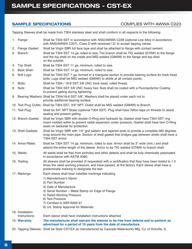
SAMPLE SPECIFICATIONS - CST-SL
COMPLIES WITH AWWA C223
Tapping Sleeves shall be made from T304 stainless steel and shall conform in all respects to the following:
1. Flange: Shall be T304 SST in accordance with ANSI/AWWA C228 (optional Low Alloy in accordance with ANSI/AWWA C207), Class D with recessed I.D. to accept tapping valves.
2. Flange Gasket: Shall be Virgin SBR full face type and shall be attached to flange with contact cement.3. Branch: Shall be T304 SST 14 ga. rolled to size. The branch shall be TIG welded (GTAW) to the flange
and the top shell on the inside and MIG welded (GMAW) to the flange and top shell on the outside.
4. Top Shell: Shall be T304 SST 12 ga. minimum, rolled to size.5. Back Shell: Shall be T304 SST 14 ga. minimum, rolled to size.
17. Armour Plates: Shall be T304 SST 14 ga. minimum, rolled to size. Armor shall be 3" wide (min.) and shall extend the
6. Stud Bars &Receiver Bars: Shall be T304 SST 10 ga. with beveled ends. Bars shall be TIG welded (GTAW) to shells
with a continuous seam.7. Receiver Lugs: Shall be T304 SST 8 ga. Lugs shall be MIG welded (GMAW) to be the receiver bars so that each stud on
the bolt bar rests between a pair of lugs and so that the flat top of the lugs provide a bearing surface forthe washer plate and nuts.
8. Studs: Shall be T304 SST 5/8 UNC, rolled threads. Studs shall be MIG welded (GMAW) to bolt bar.9. Washer Plates: Shall be T304 SST 14 ga. and shall be formed with a double lip to catch behind the receiver bar and stud
bar and thus maintain position during bolt tightening.10. Nuts: Shall be T304 /18-8 SST 5/8 UNC heavy hex. Nuts shall be coated with a Fluoropolymer Coating
to prevent galling during tightening.11. Bearing Washers: Shall be T304 SST 5/8". Washers shall be placed under each nut to provide additional
bearing surface.12. Nylon Washers: Shall be nylon 5/8". Washers shall be placed under each bearing washer to prevent binding
between the washer and washer plate.13. Test Plug Outlet: Shall be T304 SST 3/4" NPT. Outlet shall MIG welded (GMAW) to Branch.14. Test Plug: Shall be 3/4" NPT. Brass plug (T304 SST plug optional) shall have Teflon tape on threads to assist sealing
and prevent galling.15. Branch Gasket: Shall be virgin SBR with double O-Ring and hydraulic lip. Gasket shall have T304 SST ring insert molded
within to prevent radial expansion under pressure. Gasket shall have twin O-Ring seals on backside forhigh pressure protection.
16. Shell Gaskets: Shall be Virgin SBR with 1/4" grid pattern and tapered ends to provide a complete 360 degrees wraparound the main pipe. Section of shell gasket that bridges gap between shells shall have a T304 SSTarmor.
18. Welds: All welds shall be free from pinholes and other defects and shall be fully passivated in accordance withASTM A380.
entire length of the sleeve. Armor to be TIG welded (GTAW) to branch shell.
19. Testing: All sleeves shall be hydrostatically tested to 1.5 times the rated working pressure at the factory.20. Markings: Each sleeve shall bear indelible markings indicating
1) Manufacturer’s Name2) Part Number3) Date of Manufacture4) Serial Number – Metal Stamp on Edge of Flange5) Rated Working Pressure6) Test Pressure7) Certified to NSF/ANSI 618) U/L Stamp Approval for Materials
21. InstallationInstructions: Each sleeve shall have installation instructions attached.
22. Warranty: The manufacturer shall warrant the sleeves to be free from defects and to perform as advertised fora period of 10 years from the date of manufacture.
23. Tapping Sleeves: Shall be Style CST-SL as manufactured by Cascade Waterworks Mfg. Co. of Yorkville, IL.
SAMPLE SPECIFICATIONS

10
STYLE CTTL “TIGGER TEE”
STYLE CTT “TIGER TEE”
MATERIAL SPECIFICATIONS
Shell: T304 SST
Gasket: Virgin SBR
Lugs: T304 SST
Studs: 5/8 UNC, Rolled Thread, 18-8/T304 SST
Nuts: 5/8 UNC, Heavy Hex; 18-8/T304 SST Fluoropolymer Coated
MATERIAL SPECIFICATIONS
Shell: T304 SST
Gasket: Virgin SBR
Lugs: T304 SST
Studs: 5/8 UNC, Rolled Thread, 18-8/T304 SST
Nuts: 5/8 UNC, Heavy Hex; 18-8/T304 SST Fluoropolymer Coated
10 YEAR WARRANTY
Style CTT “Tiger Tee”
Style CTTL “Tigger Tee”
CASCADE warrants all model CST-EX and CST-SL All-Stainless Steel Tapping Sleeves to be free from
defects in material or workmanship and to perform as advertised for a period of 10 years from date of
shipment from CASCADE’S factory. Cascade will replace ANY uninstalled sleeve provided that the buyer
returns the sleeve freight prepaid to Cascade for inspection. Freight expenses will be reimbursed should the
sleeve be found defective. Cascade will replace any sleeve that is found to be defective while in
service, provided that an on site under pressure inspection is performed by an authorized representative of
Cascade, and that the sleeve was installed according to Cascade’s instructions and was properly supported
and blocked. Cascade’s liability in such a case shall be limited to the replacement of the sleeve. Any other
costs are excluded. This warranty specifically excludes any sleeve that is damaged during shipment, handling
or installation. Cascade is not responsible for any loss, damage or injury to any person or property directly or
indirectly arising from use or inability to use the product. User shall determine the suitability of the product prior
to its use. Unless stated in writing by Cascade, said sleeves are to be for cold water service on DIP, CIP, Steel,
PVC or A/C pipes. No claims for labor or damage will be allowed. Buyer must advise Cascade within 30 days
of discovery of the alleged defect or the claim will be barred. This warranty is exclusive and in lieu of all others
whether written, oral or implied.
STYLE CTT, CTTL
10
Shell: T -304 SST
Gasket: Virgin SBR
Lugs: T -304 SST
Studs: 18-8 SST b -11x7
Nuts: 18-8 SST b -11
MATERIAL SPECIFICATIONS
Overall Length — 8". Other sizes and ranges available upon request.
Shell: T -304 SST
Gasket: Virgin SBR
Lugs: T -304 SST
Studs: 18-8 SST b -11x7
Nuts: 18-8 SST b -11
Nominal PipeCatalog Number
Tap Size AvailableSize (Inches) I.P. or C.C.
CTT–2.13–tap2 CTT–2.38–tap 12 " CC–2"
CTT–2.63–tap22 CTT–2.88–tap 12 " CC–22 " IP
CTT–3.13–tap3 CTT–3.50–tap 12 " CC–2"
CTT–4.13–tap4 CTT–4.50–tap 2" CC–3" IP
CTT–4.80–tap
Nominal PipeCatalog Number
Tap Size AvailableSize (Inches) I.P. or C.C.
CTTL–2.13–tap2 CTTL–2.38–tap p "–12 " IP
CTTL–2.63–tap22 CTTL–2.88–tap p "–12 " IP
CTTL–3.13–tap3 CTTL–3.50–tap p "–12 " IP
CTTL–4.13–tap4 CTTL–4.50–tap p "–2" IP
CTTL–4.80–tap
250 PSI RWP 150 PSI RWP
TAPPING SADDLES
*Note: Standard 1 year Cascade warranty applies for above items.
ON ALL CST SERIES TAPPING SLEEVES
Catalog Number
CCT-2.13-tapCCT-2.38-tapCCT-2.63-tapCCT-2.88-tapCCT-3.13-tapCCT-3.50-tapCCT-4.13-tapCCT-4.50-tapCCT-4.80-tap
NominalPipe Size(inches)
2
22
3
4
Tap Size AvailableI.P. or C.C.
2” I.P. ; 12” - 2” C.C.
2” - 22” I.P. ; 12” - 2” C.C.
2” - 22” I.P. ; 12” - 2” C.C.
22” - 4” I.P. ; 2” C.C.
Catalog Number
CCTL-2.13-tapCCTL-2.38-tapCCTL-2.63-tapCCTL-2.88-tapCCTL-3.13-tapCCTL-3.50-tapCCTL-4.13-tapCCTL-4.50-tapCCTL-4.80-tap
NominalPipe Size(inches)
2
22
3
4
Tap Size AvailableI.P. or C.C.
p” - 12” I.P. ; p” - 14” C.C.
p” - 12” I.P. ; p” - 14” C.C.
p” - 12” I.P. ; p” - 14” C.C.
p” - 2” I.P. ; p” - 12” C.C.
10
ON ALL CST SERIES TAPPING SLEEVES
Catalog Number
CTT-2.13-tapCTT-2.38-tapCTT-2.63-tapCTT-2.88-tapCTT-3.13-tapCTT-3.50-tap CTT-3.96-tapCTT-4.13-tapCTT-4.50-tapCTT-4.80-tap
NominalPipe Size(inches)
2
22
3 ‡
4 ‡
Tap Size AvailableI.P. or C.C.
2” I.P. ; 12” - 2” C.C.
2” - 22” I.P. ; 12” - 2” C.C.
2” - 3” I.P. ; 12” - 2” C.C.
22” - 4” I.P. ; 2” C.C.
Catalog Number
CTTL-2.13-tapCTTL-2.38-tapCTTL-2.63-tapCTTL-2.88-tapCTTL-3.13-tapCTTL-3.50-tapCTTL-3.96-tapCTTL-4.13-tapCTTL-4.50-tapCTTL-4.80-tap
NominalPipe Size(inches)
2
22
3
4
Tap Size AvailableI.P. or C.C.
p” - 12” I.P. ; p” - 114” C.C.
p” - 12” I.P. ; p” - 114” C.C.
p” - 12” I.P. ; p” - 114” C.C.
p” - 2” I.P. ; p” - 2” C.C.
10
Overall Length — 8”. Other sizes and ranges available upon request.‡ - Standard Length is 12” for 3” & 4” taps that are onsize
18-8/T-304 SST b-11UNC, Rolled Thread
18-8/T-304 SST b-11UNC, Rolled Thread
18-8/T-304 SST b-11 Xylan Coated Heavy Hex Nut
18-8/T-304 SST b-11 Xylan Coated Heavy Hex Nut
Style CTTL “Tigger Tee”
Cascade_CST 4pager 051514 9/12/09 6:11 PM Page 4
NOTE: Other sizes and ranges available upon request.‡ - Standard Length is 12” for 3” & 4” taps that are size-on-size.
*Note: Cascade’s standard 1 year warranty applies for these items.
NOTE: Other sizes and ranges available upon request.‡ - Standard Length is 12” for 3” & 4” taps that are size-on-size
*Note: Cascade’s standard 1 year warranty applies for these items.
OVERALL LENGTH – 8”
OVERALL LENGTH – 8”
11
PIPE OUTSIDE DIAMETER GUIDE
Mac
hine
d En
d
Flui
d-Ti
te R
ough
Bar
rel
Flin
lite
Roug
h Ba
rrel
Ring
-Tite
Rou
gh B
arre
l
Perm
aflex
Rou
gh B
arre
l
Mini
mum
Std
. Rou
gh B
arre
l
Max
imum
Std
. Rou
gh B
arre
l
Mac
hine
d En
d
Flui
d-Ti
te R
ough
Bar
rel
Flin
lite
Roug
h Ba
rrel
Ring
-Tite
Rou
gh B
arre
l
Perm
aflex
Rou
gh B
arre
l
Mini
mum
Std
. Rou
gh B
arre
l
Max
imum
Std
. Rou
gh B
arre
l
1/2
3/4
11-
1/4
1-1/
22
2-1/
23
45
68
1012
1415
1618
2021
2427
3036
4248
5460
64
3.96
4.80
6.90
9.05
11.1
013
.20
15.3
0
17.4
019
.50
21.6
0
25.8
0
32.0
038
.30
44.5
050
.80
57.5
661
.61
65.6
7
3.96
4.80
6.90
9.05
11.1
013
.20
15.3
0
17.4
019
.50
21.6
0
25.8
0
32.0
0
2.50
3.80
4.80
6.90
9.05
11.1
013
.20
15.3
0
17.4
019
.50
21.6
0
25.8
0
31.7
437
.96
44.2
050
.50
3.96
5.00
7.10
9.05
11.1
013
.20
15.3
0
17.4
019
.50
21.6
0
25.8
0
32.0
038
.30
44.5
050
.80
3.96
5.00
7.10
9.30
11.4
013
.50
15.6
5
17.8
019
.92
22.0
6
26.3
2
32.4
038
.70
45.1
051
.40
3.96
5.00
7.10
9.30
11.4
013
.50
15.6
5
17.8
019
.92
22.0
6
26.3
2
32.7
439
.16
45.5
851
.98
0.63
0.88
1.13
1.38
1.63
2.13
2.63
3.13
4.13
5.13
6.13
0.84
1.05
1.32
1.66
1.90
2.38
2.88
3.50
4.50
5.56
6.63
8.63
10.7
512
.75
14.0
0
16.0
018
.00
20.0
0
24.0
0
30.0
036
.00
42.0
048
.00
60
.00
0.84
1.05
1.32
1.66
1.90
2.38
2.88
3.50
4.50
6.63
8.63
10.7
512
.75
16.0
018
.00
20.0
0
24.0
0
30.0
036
.00
42.0
048
.00
54.0
060
.00
64.0
0
4.
80
6.
909.
0511
.10
13.2
015
.30
17
.40
19.5
021
.60
25
.80
32
.00
38.3
044
.50
50.8
057
.56
61.6
1
2.38
2.88
3.50
4.50
6.63
8.63
10.7
512
.75
14.0
0
16.0
018
.00
20.0
0
24.0
0
30.0
036
.00
42.0
048
.00
54.0
060
.00
64.0
0
4.
13
6.
148.
1610
.20
12.2
414
.28
15.3
0
18.7
0
24
.80
4.
22
6.
288.
4010
.50
12.5
0
15.3
0
18.7
0
22.0
524
.80
27.9
532
.00
38.3
044
.50
50.8
0
0.84
1.05
1.32
1.66
1.90
2.38
2.88
3.50
4.50
5.56
6.63
8.63
10.7
512
.75
14.0
0
16.0
018
.00
20.0
0
24.0
0
30.0
036
.00
42.0
048
.00
3.96
4.80
6.90
9.05
11.1
013
.20
15.3
0
17.4
019
.50
21.6
0
25.8
0
32.0
038
.30
44.5
050
.80
4.
60
6.
809.
5011
.60
14.2
0
17.7
0
21.6
0
28
.70
35
.40
41.0
048
.10
54.4
0
4.
70
6.
909.
4011
.90
14.2
0
17.7
0
21.5
0
28
.40
36
.00
41.4
048
.00
55.0
0
67.3
0
4.
78
6.
929.
1111
.36
14.4
5
17.5
7
21.2
0
27
.80
35
.10
41.7
047
.70
53.6
0
66.3
0
8.81
11.0
213
.10
15
.91
19
.45
22
.99
25.7
629
.14
32.3
7
1/2
3/4
11-
1/4
1-1/
22
2-1/
23
45
68
1012
1415
1618
2021
2427
3036
4248
5460
64
3.74
4.64
6.91
9.11
11.2
413
.44
15.0
7
17.1
519
.91
22.1
2
26.4
8
33.1
2
3.93
5.05
7.16
9.32
11.4
613
.70
15.3
6
17.5
0
3.94
4.90
7.13
9.33
11.3
013
.42
15.4
5
17.6
0
3.95
4.92
7.19
9.39
11.4
713
.74
15.5
1
17.6
520
.44
22.6
8
27.1
2
33.8
0
4.
84
7.
159.
3511
.47
13.7
415
.55
17
.55
4.00
4.79
7.05
9.22
11.2
513
.37
15.3
6
17.5
020
.44
22.5
0
27.1
7
4.00
5.26
7.40
9.57
11.7
714
.04
15.8
0
17.9
420
.44
22.5
0
27.1
7
3.84
4.81
6.91
9.11
11.6
613
.92
16.2
2
18.4
620
.94
23.2
8
27.9
6
35.0
0
4.03
5.14
7.12
9.32
11.8
514
.11
16.4
1
18.6
5
4.04
5.01
7.13
9.33
11.8
814
.14
16.4
8
18.7
2
4.13
5.07
7.17
9.37
11.9
214
.18
16.4
8
18.7
221
.30
23.6
4
28.3
2
35.4
2
5.
00
7.
209.
4011
.92
14.2
016
.50
18
.75
4.10
4.97
7.07
9.27
11.8
214
.08
16.3
8
18.6
221
.20
23.5
4
28.2
2
4.10
5.32
7.37
9.62
12.1
214
.38
16.7
3
18.9
721
.20
23.5
4
28.2
2
3.84
4.81
6.91
9.11
11.6
613
.92
16.2
2
18.4
622
.18
24.6
6
29.6
2
37.0
6
4.18
5.32
7.36
9.46
11.8
814
.11
16.4
4
18.7
4
4.17
5.32
7.26
9.44
11.8
814
.14
16.5
3
18.8
4
4.17
5.33
7.32
9.50
11.9
214
.18
16.5
5
18.9
022
.54
25.0
2
29.9
8
37.4
8
5.
32
7.
269.
5011
.95
14.2
016
.55
18
.90
4.29
5.22
7.26
9.39
11.7
714
.03
16.4
4
18.7
4
4.29
5.57
7.60
9.79
12.1
214
.38
16.8
8
19.1
9
1/2
3/4
11-
1/4
1-1/
22
2-1/
23
45
68
1012
1415
1618
2021
2427
3036
4248
5460
64
CAST IRON PIPENom
inal
Pip
e Si
ze (i
nche
s)
Duct
ile Ir
on P
ipe
Class
100-
250 A
WWA C
entrif
ugal
Nom
inal
Pip
e Si
ze (i
nche
s)
Nom
inal
Pip
e Si
ze (i
nche
s)
Copp
er T
ubin
g
Stee
l Pip
e - A
NSI S
ched
ule
40/8
0
Clas
s A
AWW
A Pi
t Cas
t
Clas
s B
AWW
A Pi
t Cas
t
Clas
s C
AWW
A Pi
t Cas
t
Clas
s D
AWW
A Pi
t Cas
t
Pres
sure
Rat
ed
C900
& C
905
Sche
dule
40
/ 80
Plas
tic Ir
rigat
ion
Pipe
(PIP
)
Sew
er
IPS
DIPS
PRIN
SCO
HANC
OR
ADS
Ultra
-Rib
CAST IRON PIPEPVC HDPE
ASBESTOS-CEMENT PIPEClass 100
Mac
hine
d En
d
Flui
d-Ti
te R
ough
Bar
rel
Flin
lite
Roug
h Ba
rrel
Ring
-Tite
Rou
gh B
arre
l
Perm
aflex
Rou
gh B
arre
l
Mini
mum
Std
. Rou
gh B
arre
l
Max
imum
Std
. Rou
gh B
arre
l
Class 150 Class 200
Mac
hine
d En
d
Flui
d-Ti
te R
ough
Bar
rel
Flin
lite
Roug
h Ba
rrel
Ring
-Tite
Rou
gh B
arre
l
Perm
aflex
Rou
gh B
arre
l
Min
imum
Std
. Rou
gh B
arre
l
Max
imum
Std
. Rou
gh B
arre
l
Mac
hine
d En
d
Flui
d-Ti
te R
ough
Bar
rel
Flin
lite
Roug
h Ba
rrel
Ring
-Tite
Rou
gh B
arre
l
Perm
aflex
Rou
gh B
arre
l
Min
imum
Std
. Rou
gh B
arre
l
Max
imum
Std
. Rou
gh B
arre
l
ASBESTOS-CEMENT PIPEClass 100
Mac
hine
d En
d
Flui
d-Ti
te R
ough
Bar
rel
Flin
lite
Roug
h Ba
rrel
Ring
-Tite
Rou
gh B
arre
l
Perm
aflex
Rou
gh B
arre
l
Min
imum
Std
. Rou
gh B
arre
l
Max
imum
Std
. Rou
gh B
arre
l
Class 150 Class 200
Duct
ile Ir
on P
ipe
Copp
er T
ubin
g
Stee
l Pip
e - A
NSI S
ched
ule
40/8
0CAST IRON PIPE
Class
100-
250 A
WWA C
entrif
ugal
Clas
s A
AWW
A Pi
t Cas
t
Clas
s B
AWW
A Pi
t Cas
t
Clas
s C
AWW
A Pi
t Cas
t
Clas
s D
AWW
A Pi
t Cas
t
Pres
sure
Rat
ed
C900
& C
905
Sche
dule
40
/ 80
Plas
tic Ir
rigat
ion
Pipe
(PIP
)
Sew
er
IPS
DIPS
PRIN
SCO
HANC
OR
ADS
Ultra
-Rib
CAST IRON PIPE
PVC HDPE
Nom
inal
Pip
e Si
ze (i
nche
s)
Nom
inal
Pip
e Si
ze (i
nche
s)
Nom
inal
Pip
e Si
ze (i
nche
s)
Dual
Wal
l(S
torm
)
Dual
Wal
l(S
torm
)
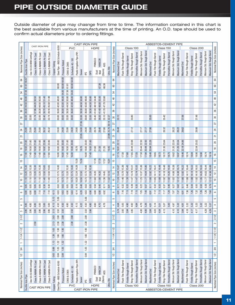
Outside diameter of pipe may chasnge from time to time. The information contained in this chart is the best available from various manufacturers at the time of printing. An O.D. tape should be used to confirm actual diameters prior to ordering fittings.

12
WARRANTYWARRANTY
Cascade Waterworks Mfg. Co. war-
rants this product for one year from the
date of purchase to be free of defects in
material or workmanship. Cascade will
repair or replace this product if it is found
to be defective within the above stated
one year warranty period provided that the
buyer submits his claim in writing and
delivers the original claimed defective
product in it’s entirety, freight prepaid to
Cascade Waterworks Mfg. Co., 1213
Badger Street, Yorkville IL, 60560 for
inspection within 30 days. Written notice or
products sent to Mfg. Reps or any other
agents prior to our review will void all war-
ranties. Cascade will not be liable or
responsible for any loss, damage or, injury
to any person(s) or property directly or
indirectly arising from the use or inability to
use this product. The user shall determine
the suitability of the product for its intend-
ed use prior to any application and said
user assumes all risks in connection with
the use of this product. No claims for any
resultant labor or damage will be allowed.
The forgoing warranties and remedies are
exclusive and in lieu of all others, whether
written, oral or implied. There is no war-
ranty on the merchandise or fitness for a
specific use of any product. Upon this
products purchase from Cascade
Waterworks Mfg. Co. or any of its
Agents, the purchaser agrees to all the
above terms of warranty.
CASCADE WATERWORKSMANUFACTURING1213 BADGER STREET YORKVILLE, ILLINOIS 60560(630) 553-0840 (800) 426-4301 FAX (630) 553-0181www.cascademfg.com
Cascade Waterworks Mfg. Co.
warrants its product(s) for one year from
the date of shipment to be free of defects
in material or workmanship. Cascade
will repair or replace this product if found
to be defective within the warranty period,
provided that the buyer submits his claim
in writing and delivers the original claimed
defective product in its entirety, freight
prepaid to Cascade Waterworks Mfg.
Co., 1213 Badger Street, Yorkville,
IL, 60560 for inspection within 30
days. Any written notice and/or product
shall be sent directly to Cascade unless
otherwise instructed. Sending these to a
manufacturer’s representative or any other
agent prior to Cascade’s review will void
all warranties. Cascade will not be liable
nor responsible for any loss, damage or
injury to any persons or property directly or
indirectly arising from the use or inability to
use this product. The user shall determine
the suitability of the product for its intended
use prior to any application and said user
assumes all risks in connection with the
use of this product. No claims for labor
or damage will be allowed. The foregoing
warranties and remedies are exclusive and
in lieu of all others, whether written, oral,
or implied. Buyer must advise Cascade
within 30 days of discovery of the alleged
defect or the claim will be barred. Upon
the products’ purchase from Cascade
Waterworks Mfg. Co., or any of its
Agents, the purchaser agrees to all of the
above terms of warranty.
Cascade Waterworks Mfg. continually improves, modifies, and updates our product literature. It is important that before any installation occurs that you refer to Cascade’s latest brochures for the appropriate product and its latest application recommendations.
CASCADE warrants all model CST-EX
and CST-SL All-Stainless Steel Tapping
Sleeves to be free from defects in
material or workmanship and to perform
as advertised for a period of 10 years
from date of shipment from CASCADE’S
factory. Cascade will replace ANY
uninstalled sleeve provided that the buyer
returns the sleeve freight prepaid to
Cascade for inspection. Freight expenses
will be reimbursed should the sleeve be
found defective. Cascade will replace any
sleeve that is found to be defective while
in service, provided that an on-site, under
pressure inspection is performed by an
authorized representative of Cascade, and
that the sleeve was installed according to
Cascade’s instructions and was properly
supported and blocked. Cascade’s
liability in such a case shall be limited
to the replacement of the sleeve. Any
other costs are excluded. This warranty
specifically excludes any sleeve that is
damaged during shipment, handling or
installation. Cascade is not responsible for
any loss, damage or injury to any person
or property directly or indirectly arising
from use or inability to use the product.
User shall determine the suitability of the
product prior to its use. Unless stated in
writing by Cascade, said sleeves are to be
for cold water service on DIP, CIP, Steel,
PVC or A/C pipes. No claims for labor or
damage will be allowed. Buyer must advise
Cascade within 30 days of discovery of the
alleged defect or the claim will be barred.
This warranty is exclusive and in lieu of all
others whether written, oral or implied.