Stainless Machine Feet (1)
134
NGI STAINLESS STEEL PRODUCTS PRODUCTS & PRICES
-
Upload
virginia-venus-visuette-marin -
Category
Documents
-
view
247 -
download
4
Transcript of Stainless Machine Feet (1)

NGISTAINLESS STEEL PRODUCTS
PRODUCTS & PRICES

STAINLESS STEEL MACHINE FEET EHEDG & 3A 1.1 TyPE xh1.2 TyPE xhf1.3 TyPE xhT1.4 TyPE xhTf
STAINLESS STEEL MACHINE FEET HYGIENIC2.1 TyPE h hyGIENIC2.2 TyPE h hyGIENIC-fIxING2.3 TyPE h hyGIENIC-fIxING-h612.4 TyPE hG hyGIENIC2.5 TyPE hJ hyGIENIC2.6 TyPE hT hyGIENIC2.7 TyPE hGT hyGIENIC2.8 TyPE T hyGIENIC2.9 TyPE M hyGIENIC2.10 TyPE M hyGIENIC-fIxING
STAINLESS STEEL MACHINE FEET3.1 TyPE h3.2 TyPE h-fIxING3.3 TyPE h-fIxING-h613.4 TyPE M3.5 TyPE M-fIxING3.6 TyPE K
STAINLESS STEEL SOLID MACHINE FEET4.1 TyPE hG4.2 TyPE hJ4.3 TyPE KG4.4 TyPE KJ4.5 TyPE G4.6 TyPE J4.7 TyPE Cf/KCf
STAINLESS STEEL FOOT PLATES5.1 TyPE hT5.2 TyPE T5.3 TyPE KT5.4 TyPE hGT
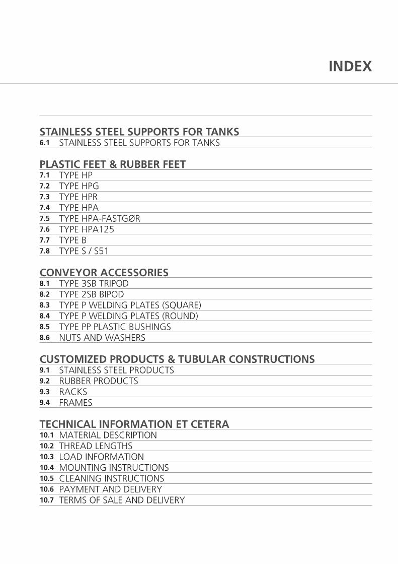
INDEX
STAINLESS STEEL SUPPORTS FOR TANKS6.1 STAINLESS STEEL SUPPORTS fOR TANKS
PLASTIC FEET & RUBBER FEET7.1 TyPE hP7.2 TyPE hPG7.3 TyPE hPR7.4 TyPE hPA7.5 TyPE hPA-fASTGØR7.6 TyPE hPA1257.7 TyPE B7.8 TyPE S / S51
CONVEYOR ACCESSORIES8.1 TyPE 3SB TRIPOD8.2 TyPE 2SB BIPOD8.3 TyPE P WELDING PLATES (SQUARE)8.4 TyPE P WELDING PLATES (ROUND)8.5 TyPE PP PLASTIC BUShINGS8.6 NUTS AND WAShERS
CUSTOMIZED PRODUCTS & TUBULAR CONSTRUCTIONS9.1 STAINLESS STEEL PRODUCTS9.2 RUBBER PRODUCTS9.3 RACKS9.4 fRAMES
TECHNICAL INFORMATION ET CETERA10.1 MATERIAL DESCRIPTION10.2 ThREAD LENGThS10.3 LOAD INfORMATION10.4 MOUNTING INSTRUCTIONS10.5 CLEANING INSTRUCTIONS10.6 PAyMENT AND DELIVERy10.7 TERMS Of SALE AND DELIVERy

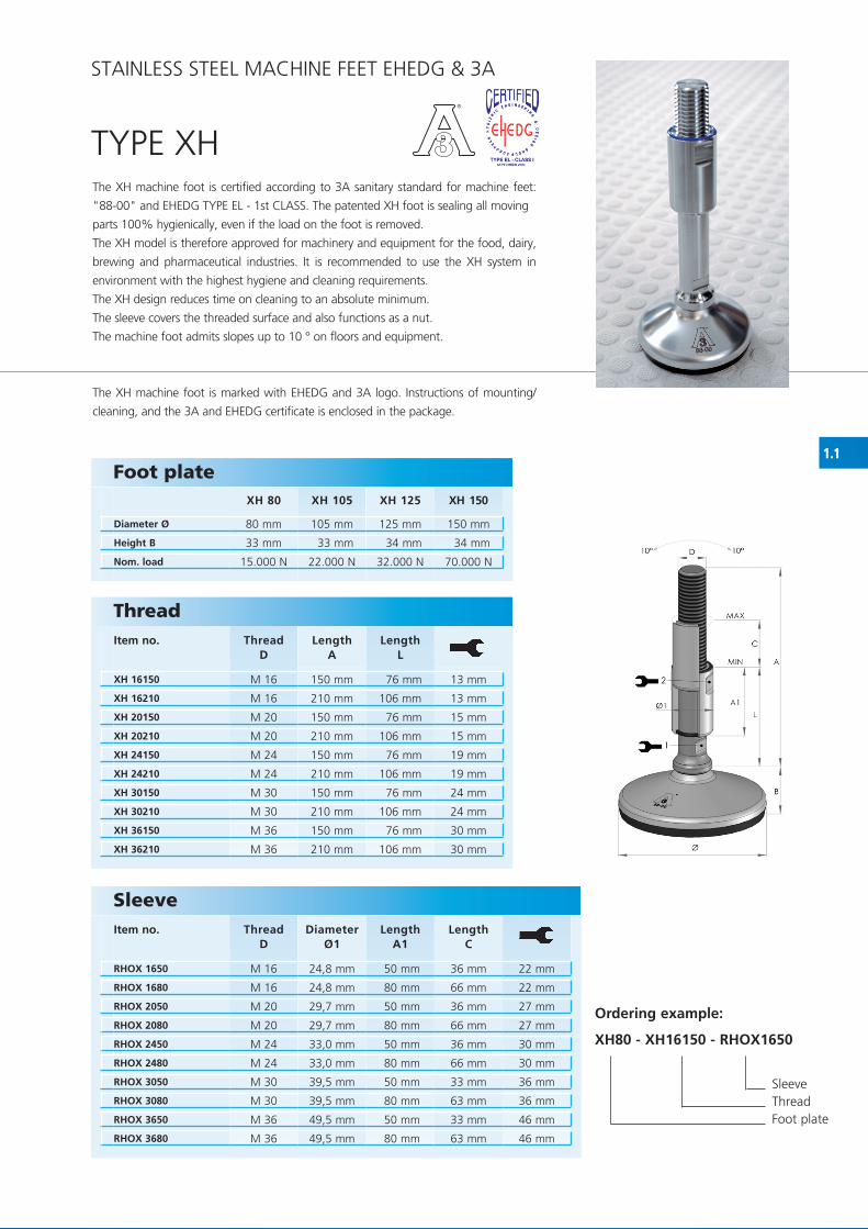
1.1
XH 80 XH 105 XH 125 XH 150
80 mm 105 mm 125 mm 150 mm
33 mm 33 mm 34 mm 34 mm
15.000 N 22.000 N 32.000 N 70.000 N
XH 16150 M 16 150 mm 76 mm 13 mm
XH 16210 M 16 210 mm 106 mm 13 mm
XH 20150 M 20 150 mm 76 mm 15 mm
XH 20210 M 20 210 mm 106 mm 15 mm
XH 24150 M 24 150 mm 76 mm 19 mm
XH 24210 M 24 210 mm 106 mm 19 mm
XH 30150 M 30 150 mm 76 mm 24 mm
XH 30210 M 30 210 mm 106 mm 24 mm
XH 36150 M 36 150 mm 76 mm 30 mm
XH 36210 M 36 210 mm 106 mm 30 mm
RHOX 1650 M 16 24,8 mm 50 mm 36 mm 22 mm
RHOX 1680 M 16 24,8 mm 80 mm 66 mm 22 mm
RHOX 2050 M 20 29,7 mm 50 mm 36 mm 27 mm
RHOX 2080 M 20 29,7 mm 80 mm 66 mm 27 mm
RHOX 2450 M 24 33,0 mm 50 mm 36 mm 30 mm
RHOX 2480 M 24 33,0 mm 80 mm 66 mm 30 mm
RHOX 3050 M 30 39,5 mm 50 mm 33 mm 36 mm
RHOX 3080 M 30 39,5 mm 80 mm 63 mm 36 mm
RHOX 3650 M 36 49,5 mm 50 mm 33 mm 46 mm
RHOX 3680 M 36 49,5 mm 80 mm 63 mm 46 mm
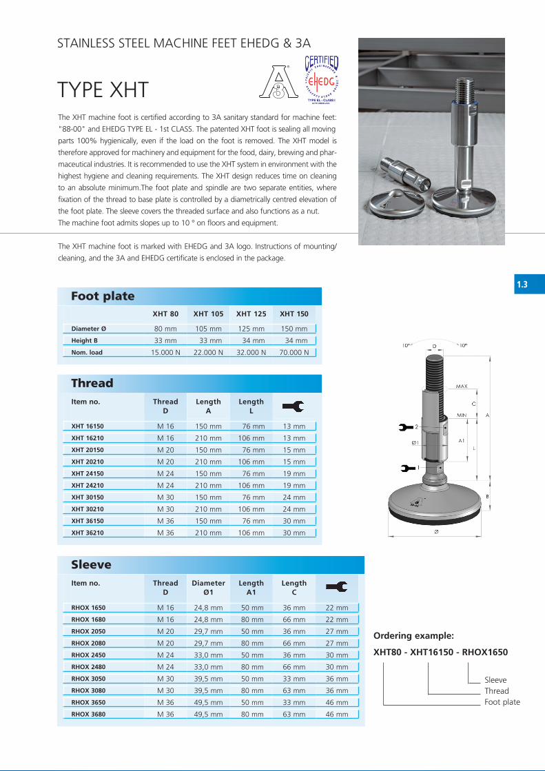
TyPE xhThe xh machine foot is certified according to 3A sanitary standard for machine feet:
"88-00" and EhEDG TyPE EL - 1st CLASS. The patented xh foot is sealing all moving
parts 100% hygienically, even if the load on the foot is removed.
The xh model is therefore approved for machinery and equipment for the food, dairy,
brewing and pharmaceutical industries. It is recommended to use the xh system in
environment with the highest hygiene and cleaning requirements.
The xh design reduces time on cleaning to an absolute minimum.
The sleeve covers the threaded surface and also functions as a nut.
The machine foot admits slopes up to 10 ° on floors and equipment.
The xh machine foot is marked with EhEDG and 3A logo. Instructions of mounting/
cleaning, and the 3A and EhEDG certificate is enclosed in the package.
Foot plate
Diameter Ø
Height B
Nom. load
STAINLESS STEEL MAChINE fEET EhEDG & 3A
ThreadItem no. Thread
DLength
ALength
L
Sleeve Item no. Thread
DDiameter
Ø1Length
A1Length
C
Ordering example:
XH80 - XH16150 - RHOX1650
Sleeve Thread foot plate

1.2
XHF 80 XHF 105 XHF 125 XHF 150
80 mm 105 mm 125 mm 150 mm
33 mm 33 mm 34 mm 34 mm
15.000 N 22.000 N 32.000 N 70.000 N
S60/80/115/215 (S1) 60 mm 80 mm 115 mm 215 mm 22 mm
S100/40/155/255 (S2) 100 mm 40 mm 155 mm 255 mm 22 mm
S170/0/246/346 (S3) 170 mm 0 mm 246 mm 346 mm 22 mm
F100x100x74,2x60x13 (F1) 100 mm 100 mm 74,2 mm 60 mm 10 mm Ø13
F100x100x74,2x74,2x9 (F2) 100 mm 100 mm 74,2 mm 74,2 mm 10 mm Ø9
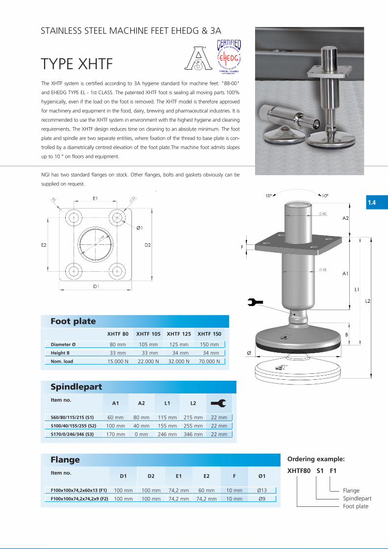
The xhf system is certified according to 3A hygiene standard for machine feet: "88-00"
and EhEDG TyPE EL - 1st CLASS. The patented xhf foot is sealing all moving
parts 100% hygienically, even if the load on the foot is removed.
The xhf model is therefore approved for machinery and equipment in the food, dairy,
brewing and pharmaceutical industries.
It is recommended to use the xhf system in environment with the highest hygiene and
cleaning requirements.
The xhf design reduces time on cleaning to an absolute minimum.
The machine foot admits slopes up to 10 ° on floors and equipment.
NGI has two standard flanges on stock. Other flanges, bolts and gaskets
obviously can be supplied on request.
TyPE xhf
Foot plate
Diameter Ø
Height B
Nom. load
SpindlepartItem no.
A1 A2 L1 L2
FlangeItem no.
D1 D2 E1 E2 F Ø1
Ordering example:
XHF80 S1 F1
flange Spindlepart foot plate
STAINLESS STEEL MAChINE fEET EhEDG & 3A

1.2.1
TyPE xhf
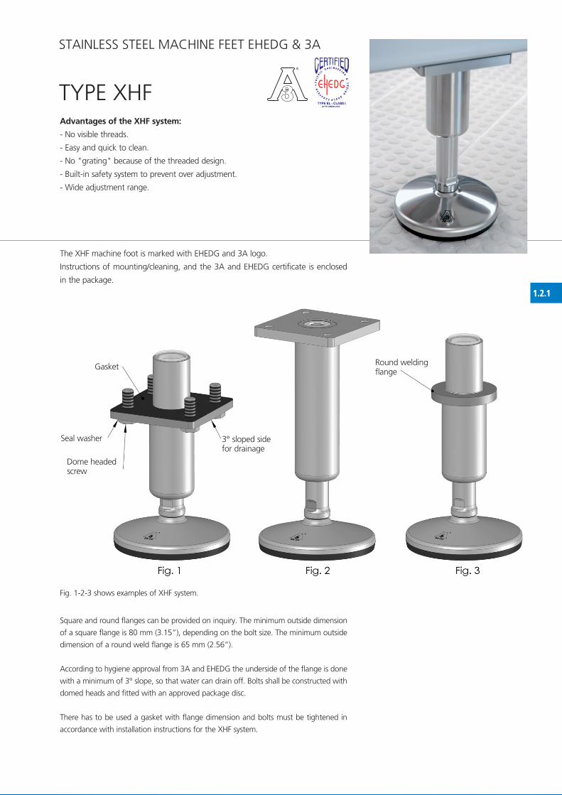
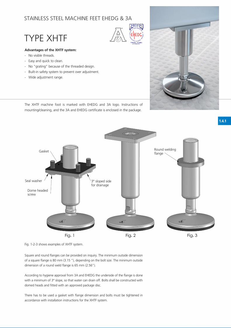
Square and round flanges can be provided on inquiry. The minimum outside dimension
of a square flange is 80 mm (3.15”), depending on the bolt size. The minimum outside
dimension of a round weld flange is 65 mm (2.56”).
According to hygiene approval from 3A and EhEDG the underside of the flange is done
with a minimum of 3° slope, so that water can drain off. Bolts shall be constructed with
domed heads and fitted with an approved package disc.
There has to be used a gasket with flange dimension and bolts must be tightened in
accordance with installation instructions for the xhf system.
fig. 1-2-3 shows examples of xhf system.
Gasket
Seal washer
Dome headedscrew
3° sloped sidefor drainage
Round weldingflange
Advantages of the XHF system:
- No visible threads.
- Easy and quick to clean.
- No "grating" because of the threaded design.
- Built-in safety system to prevent over adjustment.
- Wide adjustment range.
The xhf machine foot is marked with EhEDG and 3A logo.
Instructions of mounting/cleaning, and the 3A and EhEDG certificate is enclosed
in the package.
STAINLESS STEEL MAChINE fEET EhEDG & 3A

1.3
XHT 80 XHT 105 XHT 125 XHT 150
80 mm 105 mm 125 mm 150 mm
33 mm 33 mm 34 mm 34 mm
15.000 N 22.000 N 32.000 N 70.000 N
XHT 16150 M 16 150 mm 76 mm 13 mm
XHT 16210 M 16 210 mm 106 mm 13 mm
XHT 20150 M 20 150 mm 76 mm 15 mm
XHT 20210 M 20 210 mm 106 mm 15 mm
XHT 24150 M 24 150 mm 76 mm 19 mm
XHT 24210 M 24 210 mm 106 mm 19 mm
XHT 30150 M 30 150 mm 76 mm 24 mm
XHT 30210 M 30 210 mm 106 mm 24 mm
XHT 36150 M 36 150 mm 76 mm 30 mm
XHT 36210 M 36 210 mm 106 mm 30 mm
RHOX 1650 M 16 24,8 mm 50 mm 36 mm 22 mm
RHOX 1680 M 16 24,8 mm 80 mm 66 mm 22 mm
RHOX 2050 M 20 29,7 mm 50 mm 36 mm 27 mm
RHOX 2080 M 20 29,7 mm 80 mm 66 mm 27 mm
RHOX 2450 M 24 33,0 mm 50 mm 36 mm 30 mm
RHOX 2480 M 24 33,0 mm 80 mm 66 mm 30 mm
RHOX 3050 M 30 39,5 mm 50 mm 33 mm 36 mm
RHOX 3080 M 30 39,5 mm 80 mm 63 mm 36 mm
RHOX 3650 M 36 49,5 mm 50 mm 33 mm 46 mm
RHOX 3680 M 36 49,5 mm 80 mm 63 mm 46 mm
TyPE xhTThe xhT machine foot is certified according to 3A sanitary standard for machine feet:
"88-00" and EhEDG TyPE EL - 1st CLASS. The patented xhT foot is sealing all moving
parts 100% hygienically, even if the load on the foot is removed. The xhT model is
therefore approved for machinery and equipment for the food, dairy, brewing and phar-
maceutical industries. It is recommended to use the xhT system in environment with the
highest hygiene and cleaning requirements. The xhT design reduces time on cleaning
to an absolute minimum.The foot plate and spindle are two separate entities, where
fixation of the thread to base plate is controlled by a diametrically centred elevation of
the foot plate. The sleeve covers the threaded surface and also functions as a nut.
The machine foot admits slopes up to 10 ° on floors and equipment.
The xhT machine foot is marked with EhEDG and 3A logo. Instructions of mounting/
cleaning, and the 3A and EhEDG certificate is enclosed in the package.
Foot plate
Diameter Ø
Height B
Nom. load
ThreadItem no. Thread
DLength
ALength
L
Sleeve Item no. Thread
DDiameter
Ø1Length
A1Length
C
Ordering example:
XHT80 - XHT16150 - RHOX1650
Sleeve Thread foot plate
STAINLESS STEEL MAChINE fEET EhEDG & 3A

1.4
XHTF 80 XHTF 105 XHTF 125 XHTF 150
80 mm 105 mm 125 mm 150 mm
33 mm 33 mm 34 mm 34 mm
15.000 N 22.000 N 32.000 N 70.000 N
S60/80/115/215 (S1) 60 mm 80 mm 115 mm 215 mm 22 mm
S100/40/155/255 (S2) 100 mm 40 mm 155 mm 255 mm 22 mm
S170/0/246/346 (S3) 170 mm 0 mm 246 mm 346 mm 22 mm
F100x100x74,2x60x13 (F1) 100 mm 100 mm 74,2 mm 60 mm 10 mm Ø13
F100x100x74,2x74,2x9 (F2) 100 mm 100 mm 74,2 mm 74,2 mm 10 mm Ø9
The xhTf system is certified according to 3A hygiene standard for machine feet: "88-00"
and EhEDG TyPE EL - 1st CLASS. The patented xhTf foot is sealing all moving parts 100%
hygienically, even if the load on the foot is removed. The xhTf model is therefore approved
for machinery and equipment in the food, dairy, brewing and pharmaceutical industries. It is
recommended to use the xhTf system in environment with the highest hygiene and cleaning
requirements. The xhTf design reduces time on cleaning to an absolute minimum. The foot
plate and spindle are two separate entities, where fixation of the thread to base plate is con-
trolled by a diametrically centred elevation of the foot plate.The machine foot admits slopes
up to 10 ° on floors and equipment.
NGI has two standard flanges on stock. Other flanges, bolts and gaskets obviously can be
supplied on request.
TyPE xhTf
Foot plate
Diameter Ø
Height B
Nom. load
SpindlepartItem no.
A1 A2 L1 L2
FlangeItem no.
D1 D2 E1 E2 F Ø1
STAINLESS STEEL MAChINE fEET EhEDG & 3A
Ordering example:
XHTF80 S1 F1
flange Spindlepart foot plate

1.4.1
STAINLESS STEEL MAChINE fEET EhEDG & 3A
Square and round flanges can be provided on inquiry. The minimum outside dimension
of a square flange is 80 mm (3.15 ”), depending on the bolt size. The minimum outside
dimension of a round weld flange is 65 mm (2.56”).
According to hygiene approval from 3A and EhEDG the underside of the flange is done
with a minimum of 3° slope, so that water can drain off. Bolts shall be constructed with
domed heads and fitted with an approved package disc.
There has to be used a gasket with flange dimension and bolts must be tightened in
accordance with installation instructions for the xhTf system.
TyPE xhTfAdvantages of the XHTF system:
- No visible threads.
- Easy and quick to clean.
- No "grating" because of the threaded design.
- Built-in safety system to prevent over adjustment.
- Wide adjustment range.
The xhTf machine foot is marked with EhEDG and 3A logo. Instructions of
mounting/cleaning, and the 3A and EhEDG certificate is enclosed in the package.
fig. 1-2-3 shows examples of xhTf system.
Gasket
Seal washer
Dome headedscrew
3° sloped sidefor drainage
Round weldingflange

2.1
H 60 H 80 H 100 H 120 H 140
60 mm 80 mm 100 mm 120 mm 140 mm
25 mm 26 mm 30 mm 35 mm 37 mm
7.000 N 15.000 N 20.000 N 30.000 N 40.000 N
3A 16181 M 16 166 mm 78 mm 13 mm
3A 16231 M 16 216 mm 110 mm 13 mm
3A 20181 M 20 166 mm 78 mm 15 mm
3A 20231 M 20 216 mm 110 mm 15 mm
3A 24181 M 24 166 mm 78 mm 19 mm
3A 24231 M 24 216 mm 110 mm 19 mm
3A 30181 M 30 166 mm 78 mm 24 mm
3A 30231 M 30 216 mm 110 mm 24 mm
3A 36181 M 36 166 mm 78 mm 30 mm
3A 36231 M 36 216 mm 110 mm 30 mm
RHO 1655 M 16 24,5 mm 55 mm 40 mm 19 mm
RHO 1685 M 16 24,5 mm 85 mm 70 mm 19 mm
RHO 2055 M 20 29,9 mm 55 mm 40 mm 24 mm
RHO 2085 M 20 29,9 mm 85 mm 70 mm 24 mm
RHO 2455 M 24 33,0 mm 55 mm 40 mm 27 mm
RHO 2485 M 24 33,0 mm 85 mm 70 mm 27 mm
RHO 3055 M 30 39,5 mm 55 mm 36 mm 36 mm
RHO 3085 M 30 39,5 mm 85 mm 66 mm 36 mm
RHO 3655 M 36 49,5 mm 55 mm 36 mm 46 mm
RHO 3685 M 36 49,5 mm 85 mm 66 mm 46 mm
TyPE h hyGIENIC
Foot plate
Diameter Ø
Height B
Nom. load
STAINLESS STEEL MAChINE fEET hyGIENIC
Thread Item no. Thread
DLength
ALength
L
Sleeve Item no. Thread
DDiameter
Ø1Length
A1Length
C
Ordering example:
H80 - 3A16181 - RHO1655
Sleeve Thread foot plate
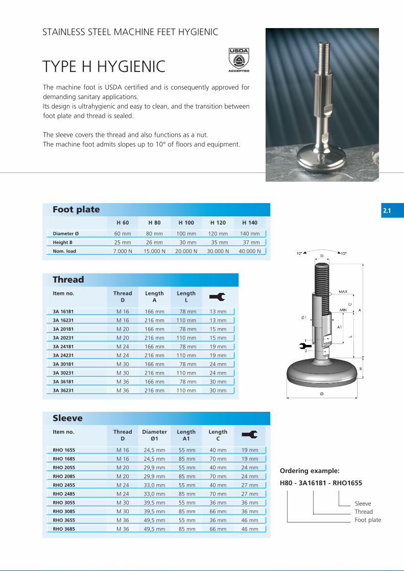
The machine foot is USDA certified and is consequently approved for demanding sanitary applications.Its design is ultrahygienic and easy to clean, and the transition between foot plate and thread is sealed.
The sleeve covers the thread and also functions as a nut.The machine foot admits slopes up to 10° of floors and equipment.

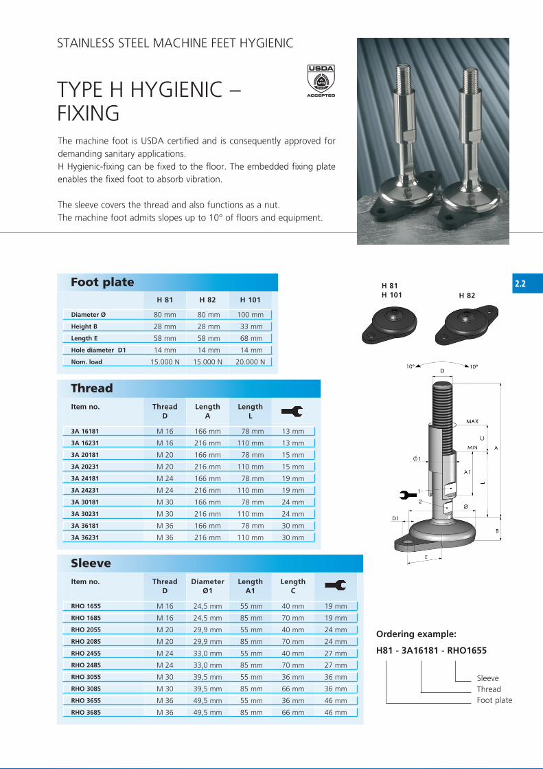
2.2H 81H 101 H 82
H 81 H 82 H 101
80 mm 80 mm 100 mm
28 mm 28 mm 33 mm
58 mm 58 mm 68 mm
14 mm 14 mm 14 mm
15.000 N 15.000 N 20.000 N
3A 16181 M 16 166 mm 78 mm 13 mm
3A 16231 M 16 216 mm 110 mm 13 mm
3A 20181 M 20 166 mm 78 mm 15 mm
3A 20231 M 20 216 mm 110 mm 15 mm
3A 24181 M 24 166 mm 78 mm 19 mm
3A 24231 M 24 216 mm 110 mm 19 mm
3A 30181 M 30 166 mm 78 mm 24 mm
3A 30231 M 30 216 mm 110 mm 24 mm
3A 36181 M 36 166 mm 78 mm 30 mm
3A 36231 M 36 216 mm 110 mm 30 mm
RHO 1655 M 16 24,5 mm 55 mm 40 mm 19 mm
RHO 1685 M 16 24,5 mm 85 mm 70 mm 19 mm
RHO 2055 M 20 29,9 mm 55 mm 40 mm 24 mm
RHO 2085 M 20 29,9 mm 85 mm 70 mm 24 mm
RHO 2455 M 24 33,0 mm 55 mm 40 mm 27 mm
RHO 2485 M 24 33,0 mm 85 mm 70 mm 27 mm
RHO 3055 M 30 39,5 mm 55 mm 36 mm 36 mm
RHO 3085 M 30 39,5 mm 85 mm 66 mm 36 mm
RHO 3655 M 36 49,5 mm 55 mm 36 mm 46 mm
RHO 3685 M 36 49,5 mm 85 mm 66 mm 46 mm
Foot plate
Diameter Ø
Height B
Length E
Hole diameter D1
Nom. load
Sleeve Item no. Thread
DDiameter
Ø1Length
A1Length
C
Thread Item no. Thread
DLength
ALength
L
Ordering example:
H81 - 3A16181 - RHO1655
Sleeve Thread foot plate
TyPE h hyGIENIC – fIxING
STAINLESS STEEL MAChINE fEET hyGIENIC
The machine foot is USDA certified and is consequently approved for demanding sanitary applications.h hygienic-fixing can be fixed to the floor. The embedded fixing plate enables the fixed foot to absorb vibration.
The sleeve covers the thread and also functions as a nut.The machine foot admits slopes up to 10° of floors and equipment.

2.3
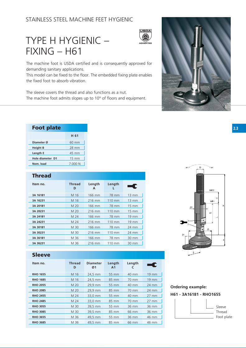
H 61
60 mm
28 mm
45 mm
15 mm
7.000 N
3A 16181 M 16 166 mm 78 mm 13 mm
3A 16231 M 16 216 mm 110 mm 13 mm
3A 20181 M 20 166 mm 78 mm 15 mm
3A 20231 M 20 216 mm 110 mm 15 mm
3A 24181 M 24 166 mm 78 mm 19 mm
3A 24231 M 24 216 mm 110 mm 19 mm
3A 30181 M 30 166 mm 78 mm 24 mm
3A 30231 M 30 216 mm 110 mm 24 mm
3A 36181 M 36 166 mm 78 mm 30 mm
3A 36231 M 36 216 mm 110 mm 30 mm
RHO 1655 M 16 24,5 mm 55 mm 40 mm 19 mm
RHO 1685 M 16 24,5 mm 85 mm 70 mm 19 mm
RHO 2055 M 20 29,9 mm 55 mm 40 mm 24 mm
RHO 2085 M 20 29,9 mm 85 mm 70 mm 24 mm
RHO 2455 M 24 33,0 mm 55 mm 40 mm 27 mm
RHO 2485 M 24 33,0 mm 85 mm 70 mm 27 mm
RHO 3055 M 30 39,5 mm 55 mm 36 mm 36 mm
RHO 3085 M 30 39,5 mm 85 mm 66 mm 36 mm
RHO 3655 M 36 49,5 mm 55 mm 36 mm 46 mm
RHO 3685 M 36 49,5 mm 85 mm 66 mm 46 mm
Foot plate
Diameter Ø
Height B
Length E
Hole diameter D1
Nom. load
Sleeve Item no. Thread
DDiameter
Ø1Length
A1Length
C
Thread Item no. Thread
DLength
ALength
L
Ordering example:
H61 - 3A16181 - RHO1655
Sleeve Thread foot plate
TyPE h hyGIENIC – fIxING – h61
STAINLESS STEEL MAChINE fEET hyGIENIC
The machine foot is USDA certified and is consequently approved for demanding sanitary applications.This model can be fixed to the floor. The embedded fixing plate enables the fixed foot to absorb vibration.
The sleeve covers the thread and also functions as a nut.The machine foot admits slopes up to 10° of floors and equipment.

2.4
3A 16181 M 16 166 mm 78 mm 13 mm
3A 16231 M 16 216 mm 110 mm 13 mm
3A 20181 M 20 166 mm 78 mm 15 mm
3A 20231 M 20 216 mm 110 mm 15 mm
3A 24181 M 24 166 mm 78 mm 19 mm
3A 24231 M 24 216 mm 110 mm 19 mm
3A 30181 M 30 166 mm 78 mm 24 mm
3A 30231 M 30 216 mm 110 mm 24 mm
3A 36181 M 36 166 mm 78 mm 30 mm
3A 36231 M 36 216 mm 110 mm 30 mm
RHO 1655 M 16 24,5 mm 55 mm 40 mm 19 mm
RHO 1685 M 16 24,5 mm 85 mm 70 mm 19 mm
RHO 2055 M 20 29,9 mm 55 mm 40 mm 24 mm
RHO 2085 M 20 29,9 mm 85 mm 70 mm 24 mm
RHO 2455 M 24 33,0 mm 55 mm 40 mm 27 mm
RHO 2485 M 24 33,0 mm 85 mm 70 mm 27 mm
RHO 3055 M 30 39,5 mm 55 mm 36 mm 36 mm
RHO 3085 M 30 39,5 mm 85 mm 66 mm 36 mm
RHO 3655 M 36 49,5 mm 55 mm 36 mm 46 mm
RHO 3685 M 36 49,5 mm 85 mm 66 mm 46 mm
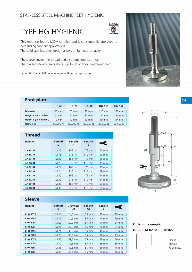
HG 60 HG 70 HG 90 HG 110 HG 150
60 mm 70 mm 90 mm 110 mm 150 mm
24 mm 24 mm 24 mm 24 mm 24 mm
19 mm 19 mm 19 mm 19 mm 19 mm
80.000 N 80.000 N 80.000 N 80.000 N 80.000 N
TyPE hG hyGIENICThis machine foot is USDA certified and is consequently approved for demanding sanitary applications.The solid stainless steel design allows a high load capacity.
The sleeve covers the thread and also functions as a nut.The machine foot admits slopes up to 9° of floors and equipment.
Type hG hyGIENIC is available with anti-slip rubber.
Foot plate
Diameter
Height B with rubber
Height B (w.o. rubber)
Nom. load
Sleeve Item no. Thread
DDiameter
Ø1Length
A1Length
C
STAINLESS STEEL MAChINE fEET hyGIENIC
Thread Item no. Thread
DLength
ALength
L
Ordering example:
HG90 - 3A16181 - RHO1655
Sleeve Thread foot plate

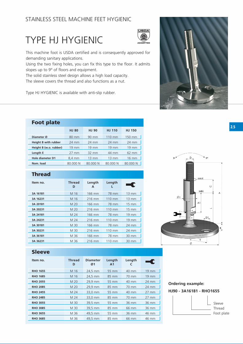
2.5HJ 80 HJ 90 HJ 110 HJ 150
80 mm 90 mm 110 mm 150 mm
24 mm 24 mm 24 mm 24 mm
19 mm 19 mm 19 mm 19 mm
27 mm 32 mm 44 mm 62 mm
8,4 mm 13 mm 13 mm 16 mm
80.000 N 80.000 N 80.000 N 80.000 N
3A 16181 M 16 166 mm 78 mm 13 mm
3A 16231 M 16 216 mm 110 mm 13 mm
3A 20181 M 20 166 mm 78 mm 15 mm
3A 20231 M 20 216 mm 110 mm 15 mm
3A 24181 M 24 166 mm 78 mm 19 mm
3A 24231 M 24 216 mm 110 mm 19 mm
3A 30181 M 30 166 mm 78 mm 24 mm
3A 30231 M 30 216 mm 110 mm 24 mm
3A 36181 M 36 166 mm 78 mm 30 mm
3A 36231 M 36 216 mm 110 mm 30 mm
RHO 1655 M 16 24,5 mm 55 mm 40 mm 19 mm
RHO 1685 M 16 24,5 mm 85 mm 70 mm 19 mm
RHO 2055 M 20 29,9 mm 55 mm 40 mm 24 mm
RHO 2085 M 20 29,9 mm 85 mm 70 mm 24 mm
RHO 2455 M 24 33,0 mm 55 mm 40 mm 27 mm
RHO 2485 M 24 33,0 mm 85 mm 70 mm 27 mm
RHO 3055 M 30 39,5 mm 55 mm 36 mm 36 mm
RHO 3085 M 30 39,5 mm 85 mm 66 mm 36 mm
RHO 3655 M 36 49,5 mm 55 mm 36 mm 46 mm
RHO 3685 M 36 49,5 mm 85 mm 66 mm 46 mm
TyPE hJ hyGIENICThis machine foot is USDA certified and is consequently approved for demanding sanitary applications.Using the two fixing holes, you can fix this type to the floor. It admits slopes up to 9° of floors and equipment.The solid stainless steel design allows a high load capacity.The sleeve covers the thread and also functions as a nut.
Type hJ hyGIENIC is available with anti-slip rubber.
Foot plate
Diameter Ø
Height B with rubber
Height B (w.o. rubber)
Length E
Hole diameter D1
Nom. load
Sleeve Item no. Thread
DDiameter
Ø1Length
A1Length
C
Thread Item no. Thread
DLength
ALength
L
Ordering example:
HJ90 - 3A16181 - RHO1655
Sleeve Thread foot plate
STAINLESS STEEL MAChINE fEET hyGIENIC

2.6
HT 60 HT 80 HT 100 HT 120 HT 140
60 mm 80 mm 100 mm 120 mm 140 mm
25 mm 26 mm 30 mm 35 mm 37 mm
7.000 N 15.000 N 20.000 N 30.000 N 40.000 N
3A 16183 M 16 166 mm 78 mm 13 mm
3A 16233 M 16 216 mm 110 mm 13 mm
3A 20183 M 20 166 mm 78 mm 15 mm
3A 20233 M 20 216 mm 110 mm 15 mm
3A 24183 M 24 166 mm 78 mm 19 mm
3A 24233 M 24 216 mm 110 mm 19 mm
3A 30183 M 30 166 mm 78 mm 24 mm
3A 30233 M 30 216 mm 110 mm 24 mm
3A 36183 M 36 166 mm 78 mm 30 mm
3A 36233 M 36 216 mm 110 mm 30 mm
RHO 1655 M 16 24,5 mm 55 mm 40 mm 19 mm
RHO 1685 M 16 24,5 mm 85 mm 70 mm 19 mm
RHO 2055 M 20 29,9 mm 55 mm 40 mm 24 mm
RHO 2085 M 20 29,9 mm 85 mm 70 mm 24 mm
RHO 2455 M 24 33,0 mm 55 mm 40 mm 27 mm
RHO 2485 M 24 33,0 mm 85 mm 70 mm 27 mm
RHO 3055 M 30 39,5 mm 55 mm 36 mm 36 mm
RHO 3085 M 30 39,5 mm 85 mm 66 mm 36 mm
RHO 3655 M 36 49,5 mm 55 mm 36 mm 46 mm
RHO 3685 M 36 49,5 mm 85 mm 66 mm 46 mm
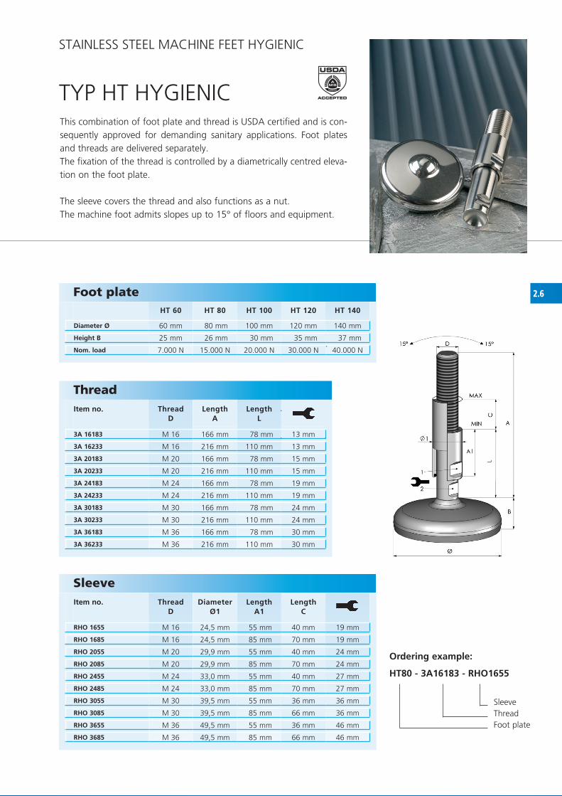
TyP hT hyGIENICThis combination of foot plate and thread is USDA certified and is con-sequently approved for demanding sanitary applications. foot plates and threads are delivered separately.The fixation of the thread is controlled by a diametrically centred eleva-tion on the foot plate.
The sleeve covers the thread and also functions as a nut.The machine foot admits slopes up to 15° of floors and equipment.
Foot plate
Diameter Ø
Height B
Nom. load
Thread Item no. Thread
DLength
ALength
L
Sleeve Item no. Thread
DDiameter
Ø1Length
A1Length
C
Ordering example:
HT80 - 3A16183 - RHO1655
Sleeve Thread foot plate
STAINLESS STEEL MAChINE fEET hyGIENIC

2.7
3A 16183 M 16 166 mm 78 mm 13 mm
3A 16233 M 16 216 mm 110 mm 13 mm
3A 20183 M 20 166 mm 78 mm 15 mm
3A 20233 M 20 216 mm 110 mm 15 mm
3A 24183 M 24 166 mm 78 mm 19 mm
3A 24233 M 24 216 mm 110 mm 19 mm
3A 30183 M 30 166 mm 78 mm 24 mm
3A 30233 M 30 216 mm 110 mm 24 mm
3A 36183 M 36 166 mm 78 mm 30 mm
3A 36233 M 36 216 mm 110 mm 30 mm
RHO 1655 M 16 24,5 mm 55 mm 40 mm 19 mm
RHO 1685 M 16 24,5 mm 85 mm 70 mm 19 mm
RHO 2055 M 20 29,9 mm 55 mm 40 mm 24 mm
RHO 2085 M 20 29,9 mm 85 mm 70 mm 24 mm
RHO 2455 M 24 33,0 mm 55 mm 40 mm 27 mm
RHO 2485 M 24 33,0 mm 85 mm 70 mm 27 mm
RHO 3055 M 30 39,5 mm 55 mm 36 mm 36 mm
RHO 3085 M 30 39,5 mm 85 mm 66 mm 36 mm
RHO 3655 M 36 49,5 mm 55 mm 36 mm 46 mm
RHO 3685 M 36 49,5 mm 85 mm 66 mm 46 mm
HGT 90 HGT 110
90 mm 110 mm
23 mm 23 mm
18 mm 18 mm
17 mm 17 mm
300.000 N 300.000 N
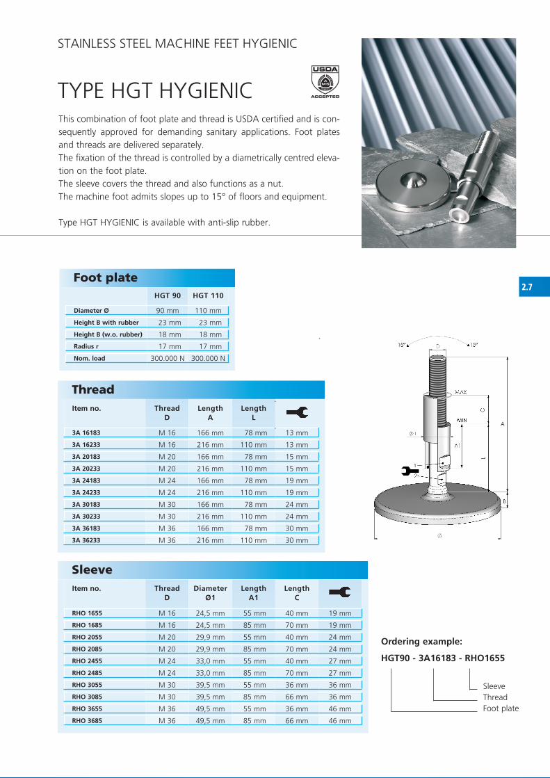
TyPE hGT hyGIENICThis combination of foot plate and thread is USDA certified and is con-sequently approved for demanding sanitary applications. foot plates and threads are delivered separately.The fixation of the thread is controlled by a diametrically centred eleva-tion on the foot plate.The sleeve covers the thread and also functions as a nut.The machine foot admits slopes up to 15° of floors and equipment.
Type hGT hyGIENIC is available with anti-slip rubber.
Thread Item no. Thread
DLength
ALength
L
Sleeve Item no. Thread
DDiameter
Ø1Length
A1Length
C
Ordering example:
HGT90 - 3A16183 - RHO1655
Sleeve Thread foot plate
STAINLESS STEEL MAChINE fEET hyGIENIC
Foot plate
Diameter Ø
Height B with rubber
Height B (w.o. rubber)
Radius r
Nom. load

2.8
T 75 T 105/21 T 105/25 T 100 T 125/25 T 125/50 T 150/25 T 150/50
75 mm 100 mm 100 mm 100 mm 125 mm 125 mm 150 mm 150 mm
22 mm 30 mm 30 mm 32 mm 37 mm 37 mm 40 mm 40 mm
14 mm 20 mm 22 mm 21 mm 26 mm 19 mm 29 mm 22 mm
10 mm 10 mm 12 mm 12 mm 12 mm 24 mm 12 mm 24 mm
12.000 N 14.000 N 14.000 N 24.000 N 30.000 N 30.000 N 45.000 N 45.000 N
RHO 1655 M 16 24,5 mm 55 mm 40 mm 19 mm
RHO 1685 M 16 24,5 mm 85 mm 70 mm 19 mm
RHO 2055 M 20 29,9 mm 55 mm 40 mm 24 mm
RHO 2085 M 20 29,9 mm 85 mm 70 mm 24 mm
RHO 2455 M 24 33,0 mm 55 mm 40 mm 27 mm
RHO 2485 M 24 33,0 mm 85 mm 70 mm 27 mm
RHO 3055 M 30 39,5 mm 55 mm 36 mm 36 mm
RHO 3085 M 30 39,5 mm 85 mm 66 mm 36 mm
RHO 3655 M 36 49,5 mm 55 mm 36 mm 46 mm
RHO 3685 M 36 49,5 mm 85 mm 66 mm 46 mm
3A 16180 M 16 180 mm 92 mm 13 mm
3A 16230 M 16 230 mm 124 mm 13 mm
3A 20180 M 20 180 mm 92 mm 15 mm
3A 20230 M 20 230 mm 124 mm 15 mm
3A 24180 M 24 180 mm 92 mm 19 mm
3A 24230 M 24 230 mm 124 mm 19 mm
3A 30180 M 30 180 mm 92 mm 24 mm
3A 30230 M 30 230 mm 124 mm 24 mm
3A 36180 M 36 185 mm 97 mm 30 mm
3A 36230 M 36 235 mm 129 mm 30 mm
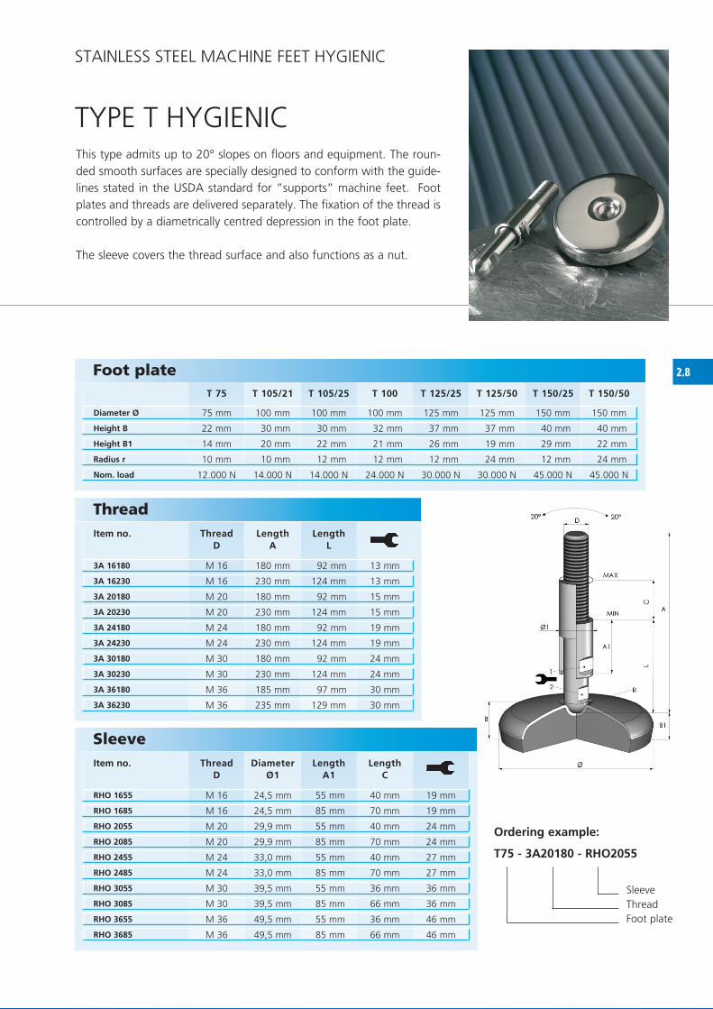
TyPE T hyGIENIC
Foot plate
Diameter Ø
Height B
Height B1
Radius r
Nom. load
Thread Item no. Thread
DLength
ALength
L
Sleeve Item no. Thread
DDiameter
Ø1Length
A1Length
C
Ordering example:
T75 - 3A20180 - RHO2055
Sleeve Thread foot plate
This type admits up to 20° slopes on floors and equipment. The roun-ded smooth surfaces are specially designed to conform with the guide-lines stated in the USDA standard for ”supports” machine feet. foot plates and threads are delivered separately. The fixation of the thread is controlled by a diametrically centred depression in the foot plate.
The sleeve covers the thread surface and also functions as a nut.
STAINLESS STEEL MAChINE fEET hyGIENIC

2.9
M 40 M 50 M 75 M 100 M 105 M 125 M 150 M 180
40 mm 50 mm 75 mm 100 mm 100 mm 125 mm 150 mm 180 mm
20 mm 21 mm 22 mm 32 mm 30 mm 37 mm 40 mm 40 mm
2.500 N 4.000 N 10.000 N 22.000 N 12.000 N 30.000 N 45.000 N 50.000 N
RHO 1655 M 16 24,5 mm 55 mm 40 mm 19 mm
RHO 1685 M 16 24,5 mm 85 mm 70 mm 19 mm
RHO 2055 M 20 29,9 mm 55 mm 40 mm 24 mm
RHO 2085 M 20 29,9 mm 85 mm 70 mm 24 mm
RHO 2455 M 24 33,0 mm 55 mm 40 mm 27 mm
RHO 2485 M 24 33,0 mm 85 mm 70 mm 27 mm
RHO 3055 M 30 39,5 mm 55 mm 36 mm 36 mm
RHO 3085 M 30 39,5 mm 85 mm 66 mm 36 mm
RHO 3655 M 36 49,5 mm 55 mm 36 mm 46 mm
RHO 3685 M 36 49,5 mm 85 mm 66 mm 46 mm
3A 16182 M 16 160 mm 72 mm 13 mm
3A 16232 M 16 210 mm 104 mm 13 mm
3A 20182 M 20 160 mm 72 mm 15 mm
3A 20232 M 20 210 mm 104 mm 15 mm
3A 24182 M 24 160 mm 72 mm 19 mm
3A 24232 M 24 210 mm 104 mm 19 mm
3A 30182 M 30 160 mm 72 mm 24 mm
3A 30232 M 30 210 mm 104 mm 24 mm
3A 36182 M 36 160 mm 72 mm 30 mm
3A 36232 M 36 210 mm 104 mm 30 mm
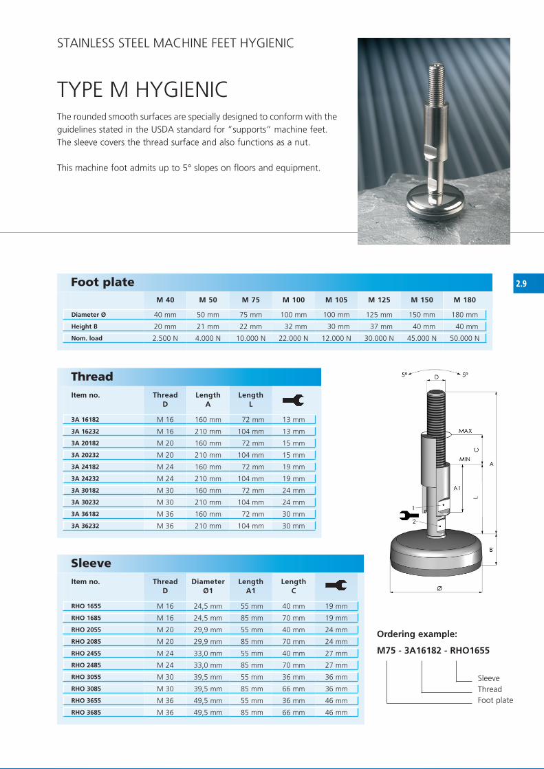
TyPE M hyGIENICThe rounded smooth surfaces are specially designed to conform with the guidelines stated in the USDA standard for ”supports” machine feet. The sleeve covers the thread surface and also functions as a nut.
This machine foot admits up to 5° slopes on floors and equipment.
Foot plate
Diameter Ø
Height B
Nom. load
ThreadItem no. Thread
DLength
ALength
L
Sleeve Item no. Thread
DDiameter
Ø1Length
A1Length
C
Ordering example:
M75 - 3A16182 - RHO1655
Sleeve Thread foot plate
STAINLESS STEEL MAChINE fEET hyGIENIC

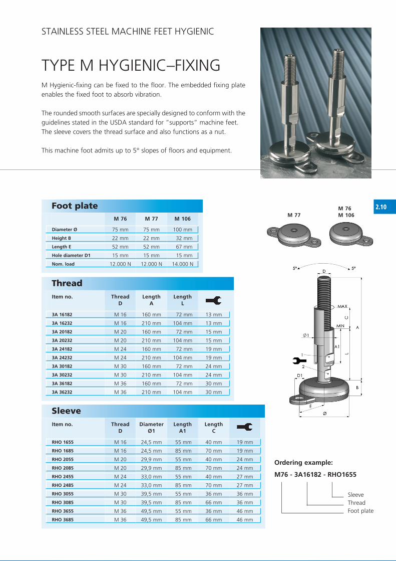
2.10M 76M 106M 77
M 76 M 77 M 106
75 mm 75 mm 100 mm
22 mm 22 mm 32 mm
52 mm 52 mm 67 mm
15 mm 15 mm 15 mm
12.000 N 12.000 N 14.000 N
RHO 1655 M 16 24,5 mm 55 mm 40 mm 19 mm
RHO 1685 M 16 24,5 mm 85 mm 70 mm 19 mm
RHO 2055 M 20 29,9 mm 55 mm 40 mm 24 mm
RHO 2085 M 20 29,9 mm 85 mm 70 mm 24 mm
RHO 2455 M 24 33,0 mm 55 mm 40 mm 27 mm
RHO 2485 M 24 33,0 mm 85 mm 70 mm 27 mm
RHO 3055 M 30 39,5 mm 55 mm 36 mm 36 mm
RHO 3085 M 30 39,5 mm 85 mm 66 mm 36 mm
RHO 3655 M 36 49,5 mm 55 mm 36 mm 46 mm
RHO 3685 M 36 49,5 mm 85 mm 66 mm 46 mm
3A 16182 M 16 160 mm 72 mm 13 mm
3A 16232 M 16 210 mm 104 mm 13 mm
3A 20182 M 20 160 mm 72 mm 15 mm
3A 20232 M 20 210 mm 104 mm 15 mm
3A 24182 M 24 160 mm 72 mm 19 mm
3A 24232 M 24 210 mm 104 mm 19 mm
3A 30182 M 30 160 mm 72 mm 24 mm
3A 30232 M 30 210 mm 104 mm 24 mm
3A 36182 M 36 160 mm 72 mm 30 mm
3A 36232 M 36 210 mm 104 mm 30 mm
TyPE M hyGIENIC–fIxING
Foot plate
Diameter Ø
Height B
Length E
Hole diameter D1
Nom. load
Thread Item no. Thread
DLength
ALength
L
Sleeve Item no. Thread
DDiameter
Ø1Length
A1Length
C
Ordering example:
M76 - 3A16182 - RHO1655
Sleeve Thread foot plate
M hygienic-fixing can be fixed to the floor. The embedded fixing plate enables the fixed foot to absorb vibration.
The rounded smooth surfaces are specially designed to conform with the guidelines stated in the USDA standard for ”supports” machine feet. The sleeve covers the thread surface and also functions as a nut.
This machine foot admits up to 5° slopes of floors and equipment.
STAINLESS STEEL MAChINE fEET hyGIENIC

3.1
H 60 H 80 H 100 H 120 H 140
60 mm 80 mm 100 mm 120 mm 140 mm
31 mm 32 mm 36 mm 41 mm 43 mm
7.000 N 15.000 N 20.000 N 30.000 N 40.000 N
DM 12
D M 16
D M 20
D M 24
D M 30
D M 36
D M 42
50 mm
70 mm
100 mm
150 mm
180 mm
230 mm
310 mm
10 mm 13 mm 17 mm 19 mm 24 mm 30 mm 36 mm
• • • • •
• • - - - - -
• • • • • • -
• • • • • • •
• • • • • • •
• • • • • • •
• • • • • • •
• • • • • • •
foot plate and thread can be combined freely.
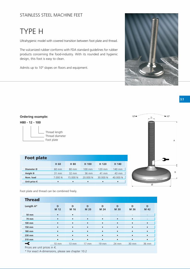
TyPE hUltrahygienic model with covered transition between foot plate and thread.
The vulcanized rubber conforms with fDA standard guidelines for rubber products concerning the food-industry. With its rounded and hygienic design, this foot is easy to clean.
Admits up to 10° slopes on floors and equipment.
STAINLESS STEEL MAChINE fEET
Prices are unit prices in €.* for exact A-dimensions, please see chapter 10.2
Ordering example:
H80 - 12 - 100
Thread lengthThread diameterfoot plate
Foot plate
Diameter Ø
Height B
Nom. load
Unit price €
ThreadLength A*

3.2
H 81H 101 H 82
DM 12
D M 16
D M 20
D M 24
D M 30
D M 36
D M 42
50 mm
70 mm
100 mm
150 mm
180 mm
230 mm
310 mm
10 mm 13 mm 17 mm 19 mm 24 mm 30 mm 36 mm
H 81 H 82 H 101
80 mm 80 mm 100 mm
34 mm 34 mm 39 mm
58 mm 58 mm 68 mm
14 mm 14 mm 14 mm
15.000 N 15.000 N 20.000 N
• • - - - - -
• • • • • • -
• • • • • • •
• • • • • • •
• • • • • • •
• • • • • • •
• • • • • • •
• • •
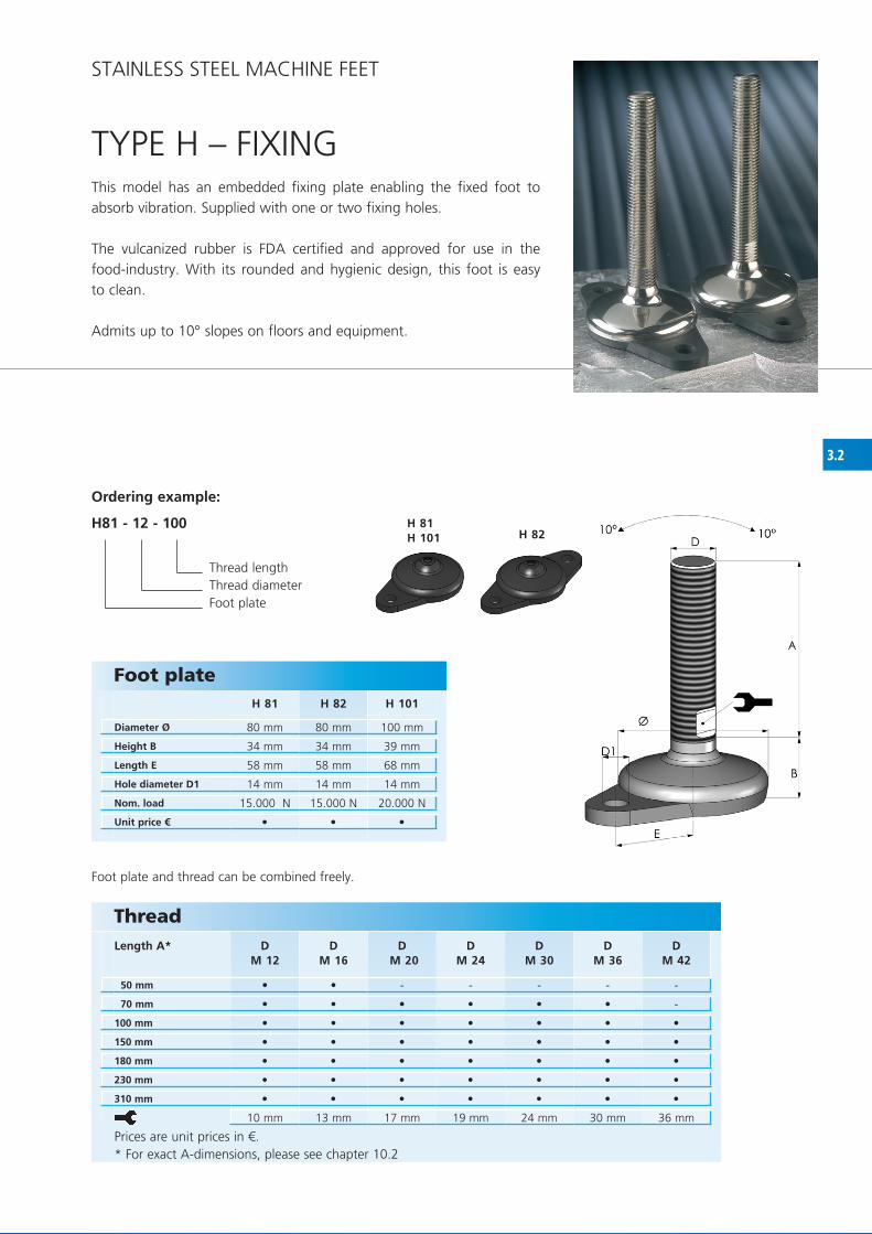
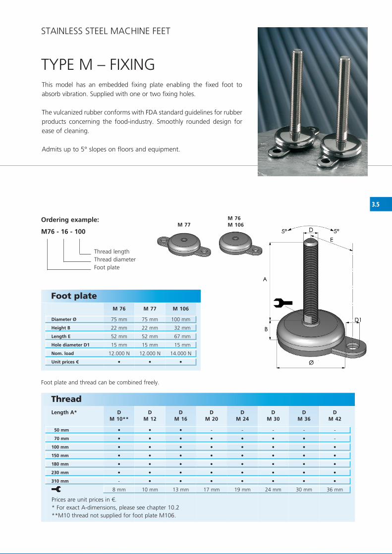
TyPE h – fIxINGThis model has an embedded fixing plate enabling the fixed foot to absorb vibration. Supplied with one or two fixing holes.
The vulcanized rubber is fDA certified and approved for use in the food-industry. With its rounded and hygienic design, this foot is easy to clean.
Admits up to 10° slopes on floors and equipment.
Ordering example:
H81 - 12 - 100
Thread lengthThread diameterfoot plate
STAINLESS STEEL MAChINE fEET
foot plate and thread can be combined freely.
ThreadLength A*
Prices are unit prices in €.* for exact A-dimensions, please see chapter 10.2
Foot plate
Diameter Ø
Height B
Length E
Hole diameter D1
Nom. load
Unit price €

3.3
DM 12
D M 16
D M 20
D M 24
D M 30
50 mm
70 mm
100 mm
150 mm
180 mm
230 mm
310 mm
10 mm 13 mm 17 mm 19 mm 24 mm
H 61
60 mm
34 mm
45 mm
15 mm
7.000 N
• • - - -
• • • • •
• • • • •
• • • • •
• • • • •
• • • • •
• • • • •
•
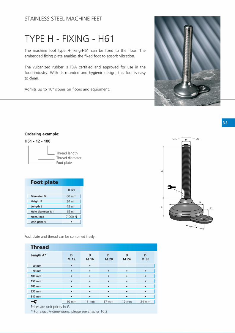
TyPE h - fIxING - h61The machine foot type h-fixing-h61 can be fixed to the floor. The embedded fixing plate enables the fixed foot to absorb vibration.
The vulcanized rubber is fDA certified and approved for use in the food-industry. With its rounded and hygienic design, this foot is easy to clean.
Admits up to 10° slopes on floors and equipment.
Ordering example:
H61 - 12 - 100
Thread lengthThread diameterfoot plate
STAINLESS STEEL MAChINE fEET
foot plate and thread can be combined freely.
ThreadLength A*
Prices are unit prices in €.* for exact A-dimensions, please see chapter 10.2
Foot plate
Diameter Ø
Height B
Length E
Hole diameter D1
Nom. load
Unit price €

3.4
M 40 M 50 M 75 M 105 M 100 M 125 M 150 M 180
40 mm 50 mm 75 mm 100 mm 100 mm 125 mm 150 mm 180 mm
20 mm 21 mm 22 mm 30 mm 32 mm 37 mm 40 mm 40 mm
2.500 N 4.000 N 10.000 N 12.000 N 22.000 N 30.000 N 45.000 N 50.000 N
DM 10**
DM 12
DM 16
DM 20
DM 24
DM 30
D M 36
DM 42
50 mm
70 mm
100 mm
150 mm
180 mm
230 mm
310 mm
8 mm 10 mm 13 mm 17 mm 19 mm 24 mm 30 mm 36 mm
• • • • • • • •
• • • - - - - -
• • • • • • • -
• • • • • • • •
• • • • • • • •
• • • • • • • •
• • • • • • • •
- • • • • • • •
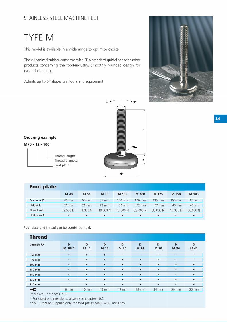
TyPE MThis model is available in a wide range to optimize choice.
The vulcanized rubber conforms with fDA standard guidelines for rubber products concerning the food-industry. Smoothly rounded design for ease of cleaning.
Admits up to 5° slopes on floors and equipment.
Foot plate
Diameter Ø
Height B
Nom. load
Unit price €
Ordering example:
M75 - 12 - 100
Thread lengthThread diameterfoot plate
STAINLESS STEEL MAChINE fEET
foot plate and thread can be combined freely.
ThreadLength A*
Prices are unit prices in €.* for exact A-dimensions, please see chapter 10.2**M10 thread supplied only for foot plates M40, M50 and M75.

3.5
M 76M 106M 77
M 76 M 77 M 106
75 mm 75 mm 100 mm
22 mm 22 mm 32 mm
52 mm 52 mm 67 mm
15 mm 15 mm 15 mm
12.000 N 12.000 N 14.000 N
DM 10**
DM 12
DM 16
DM 20
DM 24
DM 30
D M 36
DM 42
50 mm
70 mm
100 mm
150 mm
180 mm
230 mm
310 mm
8 mm 10 mm 13 mm 17 mm 19 mm 24 mm 30 mm 36 mm
• • •
• • • - - - - -
• • • • • • • -
• • • • • • • •
• • • • • • • •
• • • • • • • •
• • • • • • • •
- • • • • • • •
TyPE M – fIxING
Foot plate
Diameter Ø
Height B
Length E
Hole diameter D1
Nom. load
Unit prices €
This model has an embedded fixing plate enabling the fixed foot to absorb vibration. Supplied with one or two fixing holes.
The vulcanized rubber conforms with fDA standard guidelines for rubber products concerning the food-industry. Smoothly rounded design for ease of cleaning.
Admits up to 5° slopes on floors and equipment.
Ordering example:
M76 - 16 - 100
Thread lengthThread diameterfoot plate
STAINLESS STEEL MAChINE fEET
foot plate and thread can be combined freely.
ThreadLength A*
Prices are unit prices in €.* for exact A-dimensions, please see chapter 10.2**M10 thread not supplied for foot plate M106.

3.6
K 75 K 100 K 125
75 mm 100 mm 125 mm
21 mm 36 mm 40 mm
10.000 N 20.000 N 30.000 N
DM 12
D M 16
D M 20
D M 24
D M 30
D M 36
50 mm
70 mm
100 mm
150 mm
180 mm
230 mm
310 mm
10 mm 13 mm 17 mm 19 mm 24 mm 30 mm
• • •
• • - - - -
• • • • • •
• • • • • •
• • • • • •
• • • • • •
• • • • • •
• • • • • •
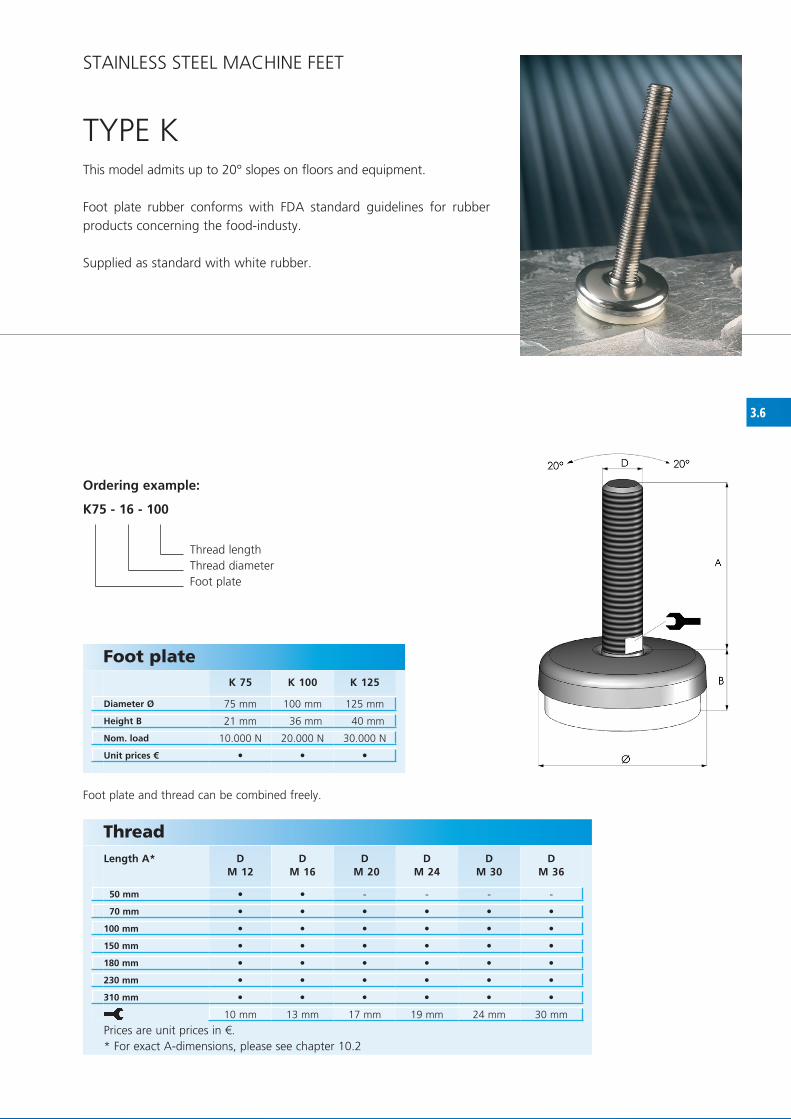
TyPE K This model admits up to 20° slopes on floors and equipment.
foot plate rubber conforms with fDA standard guidelines for rubber products concerning the food-industy.
Supplied as standard with white rubber.
Foot plate
Diameter Ø
Height B
Nom. load
Unit prices €
ThreadLength A*
Prices are unit prices in €.* for exact A-dimensions, please see chapter 10.2
Ordering example:
K75 - 16 - 100
Thread lengthThread diameterfoot plate
STAINLESS STEEL MAChINE fEET
foot plate and thread can be combined freely.

4.1
HG 60 HG 70 HG 90 HG 110 HG 150
60 mm 70 mm 90 mm 110 mm 150 mm
31 mm 31 mm 31 mm 31 mm 31 mm
26 mm 26 mm 26 mm 26 mm 26 mm
80.000 N 80.000 N 80.000 N 80.000 N 80.000 N
D M 12
DM 16
DM 20
DM 24
DM 30
DM 36
DM 42
100 mm
150 mm
180 mm
230 mm
10 mm 13 mm 17 mm 19 mm 24 mm 30 mm 36 mm
• • • • •
• • • • •
• • • • • • •
• • • • • • •
• • • • • • •
• • • • • • •
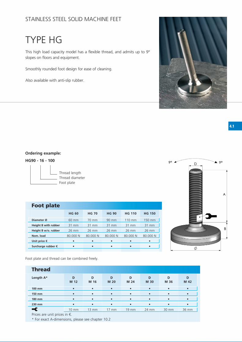
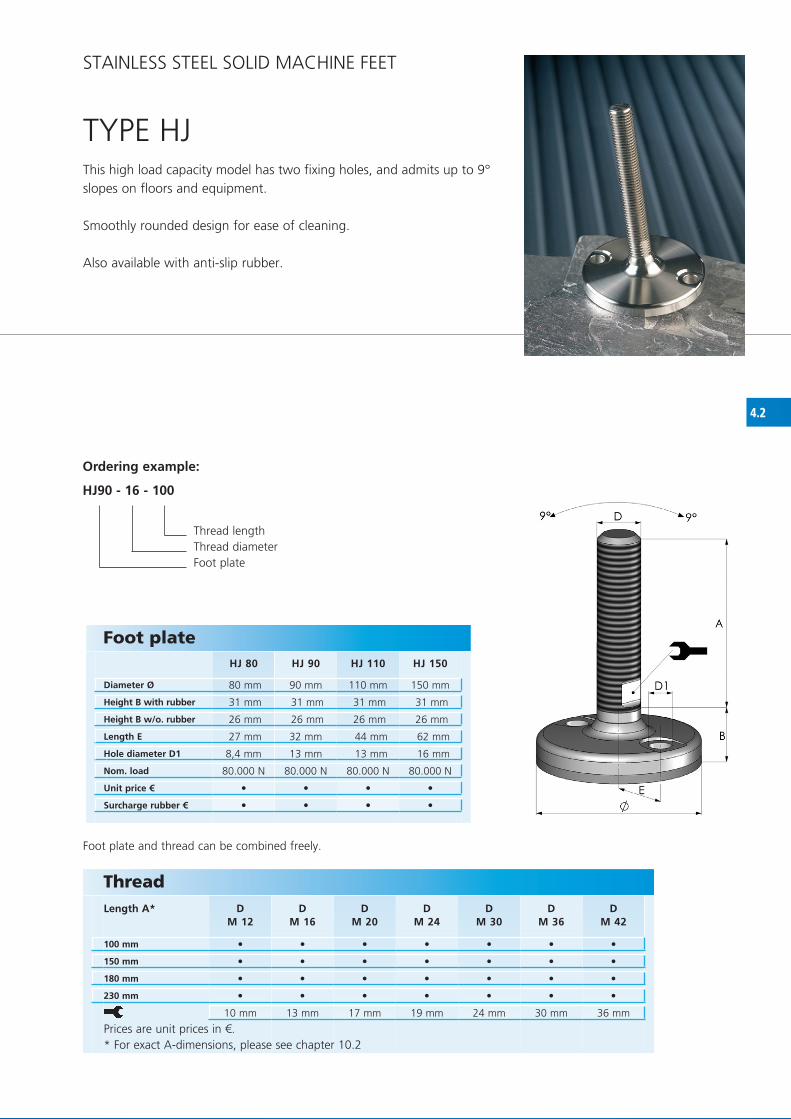
TyPE hGThis high load capacity model has a flexible thread, and admits up to 9° slopes on floors and equipment.
Smoothly rounded foot design for ease of cleaning.
Also available with anti-slip rubber.
Prices are unit prices in €.* for exact A-dimensions, please see chapter 10.2
Ordering example:
HG90 - 16 - 100
Thread lengthThread diameterfoot plate
STAINLESS STEEL SOLID MAChINE fEET
foot plate and thread can be combined freely.
Foot plate
Diameter Ø
Height B with rubber
Height B w/o. rubber
Nom. load
Unit price €
Surcharge rubber €
ThreadLength A*

4.2
HJ 80 HJ 90 HJ 110 HJ 150
80 mm 90 mm 110 mm 150 mm
31 mm 31 mm 31 mm 31 mm
26 mm 26 mm 26 mm 26 mm
27 mm 32 mm 44 mm 62 mm
8,4 mm 13 mm 13 mm 16 mm
80.000 N 80.000 N 80.000 N 80.000 N
D M 12
DM 16
DM 20
DM 24
DM 30
DM 36
DM 42
100 mm
150 mm
180 mm
230 mm
10 mm 13 mm 17 mm 19 mm 24 mm 30 mm 36 mm
• • • •
• • • •
• • • • • • •
• • • • • • •
• • • • • • •
• • • • • • •
TyPE hJThis high load capacity model has two fixing holes, and admits up to 9° slopes on floors and equipment.
Smoothly rounded design for ease of cleaning.
Also available with anti-slip rubber.
Foot plate
Diameter Ø
Height B with rubber
Height B w/o. rubber
Length E
Hole diameter D1
Nom. load
Unit price €
Surcharge rubber €
Ordering example:
HJ90 - 16 - 100
Thread lengthThread diameterfoot plate
foot plate and thread can be combined freely.
STAINLESS STEEL SOLID MAChINE fEET
ThreadLength A*
Prices are unit prices in €.* for exact A-dimensions, please see chapter 10.2

4.3
D M 12
DM 16
DM 20
DM 24
DM 30
DM 36
DM 42
100 mm
150 mm
180 mm
230 mm
10 mm 13 mm 17 mm 19 mm 24 mm 30 mm 36 mm
KG 90 KG 110 KG 150 KG 180
90 mm 110 mm 150 mm 180 mm
22 mm 22 mm 25 mm 25 mm
17 mm 17 mm 20 mm 20 mm
70.000 N 70.000 N 120.000 N 120.000 N
• • • • • • •
• • • • • • •
• • • • • • •
• • • • • • •
• • • •
• • • •
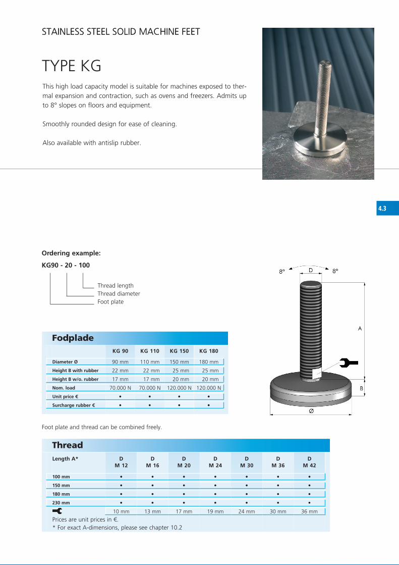
TyPE KGThis high load capacity model is suitable for machines exposed to ther-mal expansion and contraction, such as ovens and freezers. Admits up to 8° slopes on floors and equipment.
Smoothly rounded design for ease of cleaning.
Also available with antislip rubber.
Ordering example:
KG90 - 20 - 100
Thread lengthThread diameterfoot plate
foot plate and thread can be combined freely.
STAINLESS STEEL SOLID MAChINE fEET STAINLESS STEEL SOLID MAChINE fEET
ThreadLength A*
Prices are unit prices in €.* for exact A-dimensions, please see chapter 10.2
Fodplade
Diameter Ø
Height B with rubber
Height B w/o. rubber
Nom. load
Unit price €
Surcharge rubber €


4.4
KJ 90 KJ 110 KJ 150 KJ 180
90 mm 110 mm 150 mm 180 mm
22 mm 22 mm 25 mm 25 mm
17 mm 17 mm 20 mm 20 mm
32 mm 44 mm 62 mm 74 mm
13 mm 13 mm 16 mm 16 mm
70.000 N 70.000 N 120.000 N 120.000 N
D M 12
DM 16
DM 20
DM 24
DM 30
DM 36
DM 42
100 mm
150 mm
180 mm
230 mm
10 mm 13 mm 17 mm 19 mm 24 mm 30 mm 36 mm
• • • •
• • • •
• • • • • • •
• • • • • • •
• • • • • • •
• • • • • • •
TyPE KJ
Foot plate
Diameter Ø
Height B with rubber
Height B w/o. rubber
Length E
Hole diameter D1
Nom. load
Unit price €
Surcharge rubber €
This high load capacity model has 2 fixing holes, and admits up to 8° slopes on floors and equipment.
Smoothly rounded design for ease of cleaning.
Also available with anti-slip rubber.
Ordering example:
KJ90 - 16 - 100
Thread lengthThread diameterfoot plate
foot plate and thread can be combined freely.
STAINLESS STEEL SOLID MAChINE fEET
ThreadLength A*
Prices are unit prices in €.* for exact A-dimensions, please see chapter 10.2

4.5
G 90 G 110 G 150 G 180
90 mm 110 mm 150 mm 180 mm
17 mm 17 mm 17 mm 19 mm
12 mm 12 mm 12 mm 14 mm
70.000 N 70.000 N 100.000 N 120.000 N
D M 12
DM 16
DM 20
DM 24
DM 30
DM 36
DM 42
100 mm
150 mm
180 mm
230 mm
10 mm 13 mm 17 mm 19 mm 24 mm 30 mm 36 mm
• • • •
• • • •
• • • • • • •
• • • • • • •
• • • • • • •
• • • • • • •
TyPE G
Foot plate
Diameter Ø
Height B with rubber
Height B w/o. rubber
Nom. load
Unit price €
Surcharge rubber €
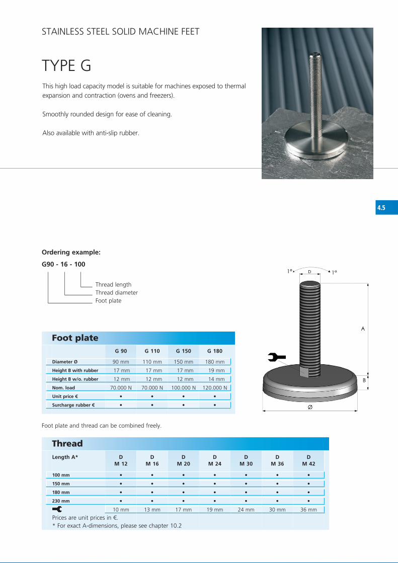
This high load capacity model is suitable for machines exposed to thermal expansion and contraction (ovens and freezers).
Smoothly rounded design for ease of cleaning.
Also available with anti-slip rubber.
Ordering example:
G90 - 16 - 100
Thread lengthThread diameterfoot plate
foot plate and thread can be combined freely.
STAINLESS STEEL SOLID MAChINE fEET
ThreadLength A*
Prices are unit prices in €.* for exact A-dimensions, please see chapter 10.2

4.6
J 90 J 110 J 150 J 180
90 mm 110 mm 150 mm 180 mm
17 mm 17 mm 17 mm 19 mm
12 mm 12 mm 12 mm 14 mm
32 mm 42 mm 59 mm 74 mm
13 mm 13 mm 16 mm 16 mm
70.000 N 70.000 N 100.000 N 120.000 N
D M 12
DM 16
DM 20
DM 24
DM 30
DM 36
DM 42
100 mm
150 mm
180 mm
230 mm
10 mm 13 mm 17 mm 19 mm 24 mm 30 mm 36 mm
• • • •
• • • •
• • • • • • •
• • • • • • •
• • • • • • •
• • • • • • •
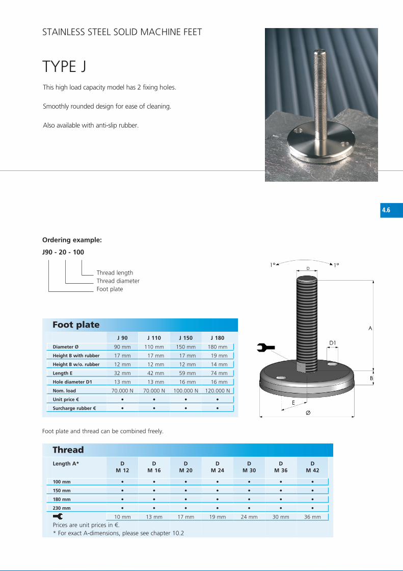
TyPE JThis high load capacity model has 2 fixing holes.
Smoothly rounded design for ease of cleaning.
Also available with anti-slip rubber.
Foot plate
Diameter Ø
Height B with rubber
Height B w/o. rubber
Length E
Hole diameter D1
Nom. load
Unit price €
Surcharge rubber €
Ordering example:
J90 - 20 - 100
Thread lengthThread diameterfoot plate
foot plate and thread can be combined freely.
STAINLESS STEEL SOLID MAChINE fEET
ThreadLength A*
Prices are unit prices in €.* for exact A-dimensions, please see chapter 10.2

4.7
CF 110 KCF 110
110 mm 110 mm
19 mm 22 mm
14 mm 17 mm
70 mm 70 mm
14,5 mm 14,5 mm
70.000 N 100.000 N
D M 12**
DM 16
DM 20
DM 24
DM 30
DM 36
DM 42
100 mm
150 mm
180 mm
230 mm
10 mm 13 mm 17 mm 19 mm 24 mm 30 mm 36 mm
• •
• •
• • • • • • •
• • • • • • •
• • • • • • •
• • • • • • •
TyPE Cf / KCf
Foot plate
Diameter Ø
Height B with rubber
Height B w/o. rubber
Length E
Hole diameter D1
Nom. load
Unit price €
Surcharge rubber €
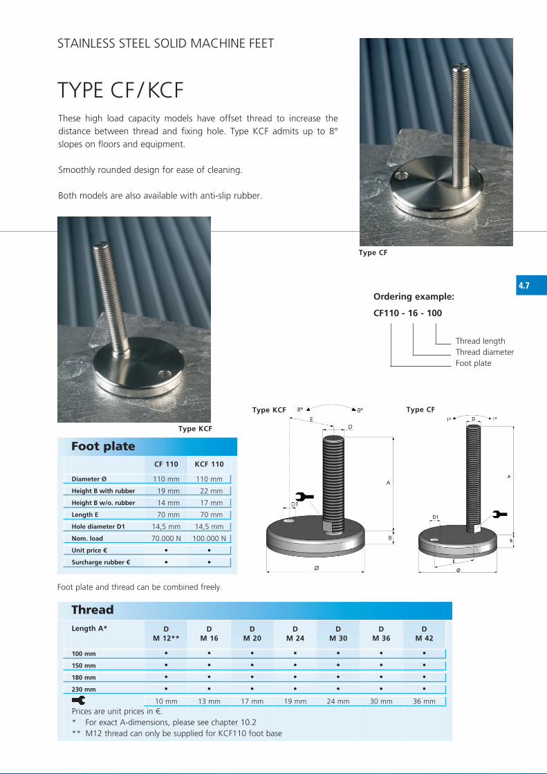
These high load capacity models have offset thread to increase the distance between thread and fixing hole. Type KCf admits up to 8° slopes on floors and equipment.
Smoothly rounded design for ease of cleaning.
Both models are also available with anti-slip rubber.
Ordering example:
CF110 - 16 - 100
Thread lengthThread diameterfoot plate
Type KCF
Type KCF
Type CF
Type CF
foot plate and thread can be combined freely.
STAINLESS STEEL SOLID MAChINE fEET
ThreadLength A*
Prices are unit prices in €.* for exact A-dimensions, please see chapter 10.2** M12 thread can only be supplied for KCf110 foot base

5.1
HT 60 HT 80 HT 100 HT 120 HT 140
60 mm 80 mm 100 mm 120 mm 140 mm
29 mm 30 mm 34 mm 39 mm 41 mm
17 mm 17 mm 17 mm 17 mm 17 mm
7.000 N 15.000 N 20.000 N 30.000 N 40.000 N
DM 24
DM 30
DM 36
DM 42
70 mm
100 mm
150 mm
180 mm
230 mm
310 mm
19 mm 24 mm 30 mm 36 mm
• • • • •
• • • -
• • • •
• • • •
• • • •
• • • •
• • • •
TyPE hT
Foot plate
Diameter Ø
Height B
Radius r
Nom. load
Unit prices €
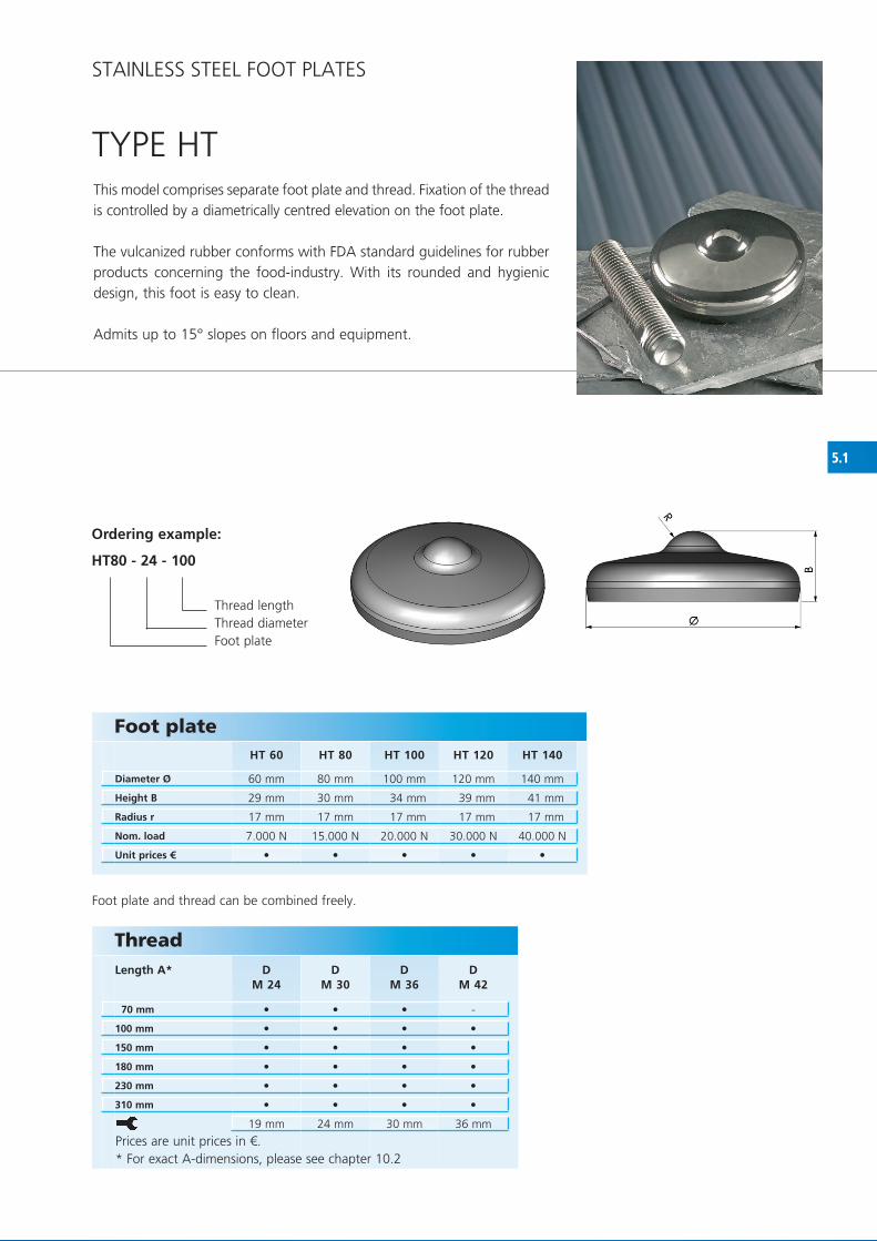
This model comprises separate foot plate and thread. fixation of the thread is controlled by a diametrically centred elevation on the foot plate.
The vulcanized rubber conforms with fDA standard guidelines for rubber products concerning the food-industry. With its rounded and hygienic design, this foot is easy to clean.
Admits up to 15° slopes on floors and equipment.
STAINLESS STEEL fOOT PLATES
ThreadLength A*
Prices are unit prices in €.* for exact A-dimensions, please see chapter 10.2
Ordering example:
HT80 - 24 - 100
Thread lengthThread diameterfoot plate
foot plate and thread can be combined freely.

5.2
T 75 T 105/21 T 105/25 T 100 T 125/25 T 125/50 T 150/25 T 150/50
75 mm 100 mm 100 mm 100 mm 125 mm 125 mm 150 mm 150 mm
22 mm 30 mm 30 mm 32 mm 37 mm 37 mm 40 mm 40 mm
14 mm 20 mm 22 mm 21 mm 26 mm 19 mm 29 mm 22 mm
10 mm 10 mm 12 mm 12 mm 12 mm 24 mm 12 mm 24 mm
12.000 N 14.000 N 14.000 N 24.000 N 30.000 N 30.000 N 45.000 N 45.000 N
DM 12
D M 16
D M 20
D M 24
D M 30
D M 36
D M 42
50 mm
70 mm
100 mm
150 mm
180 mm
230 mm
310 mm
10 mm 13 mm 17 mm 19 mm 24 mm 30 mm 36 mm
• • • • • • • •
• • - - - - -
• • • • • • -
• • • • • • •
• • • • • • •
• • • • • • •
• • • • • • •
• • • • • • •
TyPE T
Foot plate
Diameter Ø
Height B
Height B1
Radius r
Nom. load
Unit price €
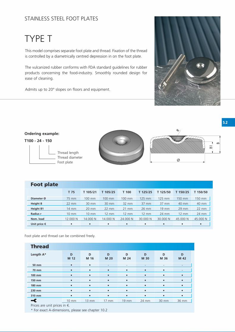
This model comprises separate foot plate and thread. fixation of the thread is controlled by a diametrically centred depression in on the foot plate.
The vulcanized rubber conforms with fDA standard guidelines for rubber products concerning the food-industry. Smoothly rounded design for ease of cleaning.
Admits up to 20° slopes on floors and equipment.
Ordering example:
T100 - 24 - 150
Thread lengthThread diameterfoot plate
foot plate and thread can be combined freely.
STAINLESS STEEL fOOT PLATES
ThreadLength A*
Prices are unit prices in €.* for exact A-dimensions, please see chapter 10.2

5.3
KT 90 KT 110 KT 130 KT 150 KT 180
90 mm 110 mm 130 mm 150 mm 180 mm
17 mm 19 mm 21 mm 21 mm 21 mm
12 mm 14 mm 16 mm 16 mm 16 mm
120.000 N 140.000 N 200.000 N 200.000 N 200.000 N
DM 12
D M 16
D M 20
D M 24
D M 30
D M 36
D M 42
50 mm
70 mm
100 mm
150 mm
180 mm
230 mm
310 mm
10 mm 13 mm 17 mm 19 mm 24 mm 30 mm 36 mm
• • - - - - -
• • • • • • -
• • • • • • •
• • • • • • •
• • • • • • •
• • • • • • •
• • • • • • •
• • • • •
• • • • •
TyPE KT
Ordering example:
KT130 - 36 - 100
Thread lengthThread diameterfoot plate
STAINLESS STEEL fOOT PLATES
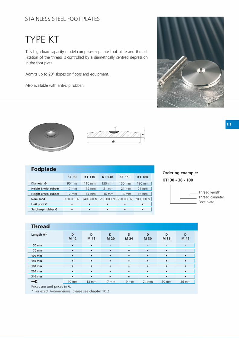
This high load capacity model comprises separate foot plate and thread. fixation of the thread is controlled by a diametrically centred depression in the foot plate.
Admits up to 20° slopes on floors and equipment.
Also available with anti-slip rubber.
ThreadLength A*
Prices are unit prices in €.* for exact A-dimensions, please see chapter 10.2
Fodplade
Diameter Ø
Height B with rubber
Height B w/o. rubber
Nom. load
Unit price €
Surcharge rubber €

5.4
HGT 90 HGT 110
90 mm 110 mm
23 mm 23 mm
18 mm 18 mm
17 mm 17 mm
300.000 N 300.000 N
D M 24
D M 30
D M 36
D M 42
70 mm
100 mm
150 mm
180 mm
230 mm
310 mm
19 mm 24 mm 30 mm 36 mm
• •
• •
• • • -
• • • •
• • • •
• • • •
• • • •
• • • •
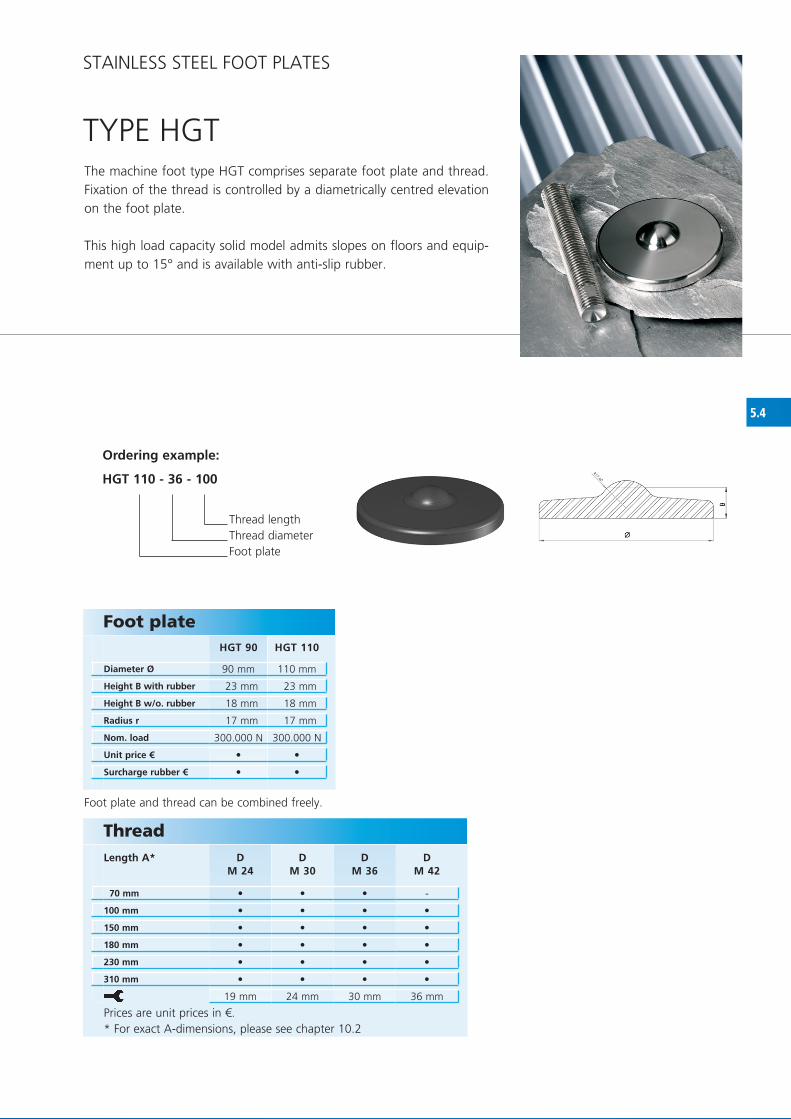
TyPE hGT
STAINLESS STEEL fOOT PLATES
The machine foot type hGT comprises separate foot plate and thread. fixation of the thread is controlled by a diametrically centred elevation on the foot plate.
This high load capacity solid model admits slopes on floors and equip-ment up to 15° and is available with anti-slip rubber.
Foot plate
Diameter Ø
Height B with rubber
Height B w/o. rubber
Radius r
Nom. load
Unit price €
Surcharge rubber €
Ordering example:
HGT 110 - 36 - 100
Thread lengthThread diameterfoot plate
ThreadLength A*
Prices are unit prices in €.* for exact A-dimensions, please see chapter 10.2
foot plate and thread can be combined freely.


6.1
1 1/2’’60 1 1/2’’ 69 mm 62 mm 60 mm 8 mm 20 mm
1 1/4’’60 1 1/4’’ 60 mm 52 mm 60 mm 8 mm 20 mm
1’’60 1’’ 60 mm 55 mm 60 mm 10 mm 35 mm
3/4’’50 3/4’’ 50 mm 45 mm 50 mm 10 mm 25 mm
1/2’’50 1/2’’ 42 mm 38 mm 50 mm 7 mm 27 mm
1 1/2’’140 1 1/2’’ 140 mm 86 mm 34 mm 24 mm 38 mm 450.000 N
1 1/4’’140 1 1/4’’ 140 mm 86 mm 34 mm 24 mm 32 mm 300.000 N
1’’140 1’’ 140 mm 65 mm 33 mm 24 mm 30 mm 200.000 N
3/4’’120 3/4’’ 120 mm 50 mm 30 mm 15 mm 24 mm 150.000 N
1/2’’120 1/2’’ 120 mm 55 mm 26 mm 15 mm 19 mm 80.000 N
KT 90 KT 110 KT 130 KT 150 KT 180
90 mm 110 mm 130 mm 150 mm 180 mm
17 mm 19 mm 21 mm 21 mm 21 mm
12 mm 14 mm 16 mm 16 mm 16 mm
120.000 N 140.000 N 200.000 N 200.000 N 200.000 N
•
•
•
•
•
•
•
•
•
•
• • • • •
• • • • •
STAINLESS STEEL SUPPORTS fOR TANKS
STAINLESS STEEL SUPPORTS fOR TANKS
This model comprises a welding connector and a round-ended thread. foot plates are recommended to prevent damage to tiled floors. Standard sizes are listed below. If required, NGI can make connectors to customized specifications.
More stainless steel foot plates can be seen in section Stainless Steel foot plates page 5.3
* ½” and ¾” thread can only be supplied for KT90 and KT110 foot base
Welding connector Designation Thread
GLength
D1Length
D2Length
A3Length
A4Length
A5Unit price £
Thread Designation Thread
GLength
ALength
A1Length
A2Radius
rNom. load
Unit price £
Foot plate
Diameter Ø
Height B with rubber
Height B w.o/rubber
Nom. load
Unit price €
Surcharge rubber €
Ordering example:
KT90 - 3/4’’120 - 3/4’’50
Connector Thread foot plate


7.1
HP 60 HP 80 HP 100 HP 120
60 mm 80 mm 100 mm 120 mm
31 mm 31 mm 37 mm 37 mm
- 27 mm 32 mm 40 mm
- 9 mm 11 mm 11 mm
15.000 N 15.000 N 20.000 N 22.000 N
DM 12
DM 16
DM 20
DM 24
70 mm
100 mm
150 mm
180 mm
230 mm
310 mm
10 mm 13 mm 17 mm 19 mm
• • • •
• • • •
• • • •
• • • •
• • • •
• • • •
• • • •
TyPE hPThe design of type hP is based on hygienic construction, mounting fle-xibility and resistance towards exterior influences.
The plastic foot offers the additional choice of fixation to the floor the floor fixing bolts are concealed under the cover and the foot admits slopes up to 10°.
Foot plate
Diameter Ø
Height B
Length E
Hole diameter D1
Nom. load
Unit price €
Ordering example:
HP80 - 16 - 100
Thread lengthThread diameterfoot plate
foot plate and thread can be combined freely.
ThreadLength A*
Prices are unit prices in €.* for exact A-dimensions, please see chapter 10.2
PLASTIC fEET & RUBBER fEET

7.2
HPG 60 HPG 80 HPG 100 HPG 120
60 mm 80 mm 100 mm 120 mm
33 mm 33 mm 39 mm 40 mm
- 27 mm 32 mm 40 mm
- 9 mm 11 mm 11 mm
15.000 N 15.000 N 20.000 N 22.000 N
DM 12
DM 16
DM 20
DM 24
70 mm
100 mm
150 mm
180 mm
230 mm
310 mm
10 mm 13 mm 17 mm 19 mm
• • • •
• • • •
• • • •
• • • •
• • • •
• • • •
• • • •
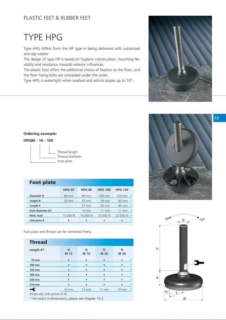
TyPE hPGType hPG differs form the hP type in being delivered with vulcanized anti-slip rubber.The design of type hP is based on hygienic construction, mounting fle-xibility and resistance towards exterior influences.The plastic foot offers the additional choice of fixation to the floor, and the floor fixing bolts are concealed under the cover.Type hPG is watertight when washed and admits slopes up to 10°.
Foot plate
Diameter Ø
Height B
Length E
Hole diameter D1
Nom. load
Unit price €
ThreadLength A*
Prices are unit prices in €.* for exact A-dimensions, please see chapter 10.2
Ordering example:
HPG80 - 16 - 100
Thread lengthThread diameterfoot plate
foot plate and thread can be combined freely.
PLASTIC fEET & RUBBER fEET

7.3
HPR 80 HPR 100 HPR120
80 mm 100 mm 120 mm
33 mm 39 mm 40 mm
27 mm 32 mm 40 mm
9 mm 11 mm 11 mm
15.000 N 20.000 N 22.000 N
DM 12
DM 16
DM 20
DM 24
70 mm
100 mm
150 mm
180 mm
230 mm
310 mm
10 mm 13 mm 17 mm 19 mm
• • •
• • • •
• • • •
• • • •
• • • •
• • • •
• • • •
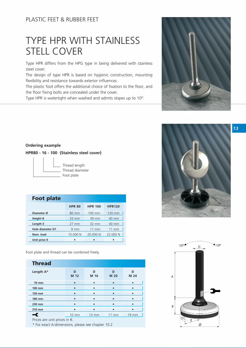
TyPE hPR WITh STAINLESS STELL COVERType hPR differs from the hPG type in being delivered with stainless steel cover.The design of type hPR is based on hygienic construction, mounting flexibility and resistance towards exterior influences.The plastic foot offers the additional choice of fixation to the floor, and the floor fixing bolts are concealed under the cover.Type hPR is watertight when washed and admits slopes up to 10°.
Foot plate
Diameter Ø
Height B
Length E
Hole diameter D1
Nom. load
Unit price €
Ordering example
HPR80 - 16 - 100 (Stainless steel cover)
Thread lengthThread diameterfoot plate
foot plate and thread can be combined freely.
ThreadLength A*
Prices are unit prices in €.* for exact A-dimensions, please see chapter 10.2
PLASTIC fEET & RUBBER fEET

7.4
HPA 40 HPA 50 HPA 60 HPA 80 HPA 100
40 mm 50 mm 60 mm 80 mm 100 mm
29 mm 35 mm 31 mm 32 mm 35 mm
28 mm 34 mm 33 mm 31 mm 34 mm
8.000 N 8.500 N 15.000 N 10.000 N 15.000 N
DM 10**
DM 12
DM 16
DM 20
DM 24
D M 30
70 mm
100 mm
150 mm
180 mm
230 mm
310 mm
8 mm 10 mm 13 mm 17 mm 19 mm 24 mm
• • • • •
• • • • •
• • • • • •
• • • • • •
• • • • • •
• • • • • •
• • • • • •
• • • • • •
foot plate and thread can be combined freely.
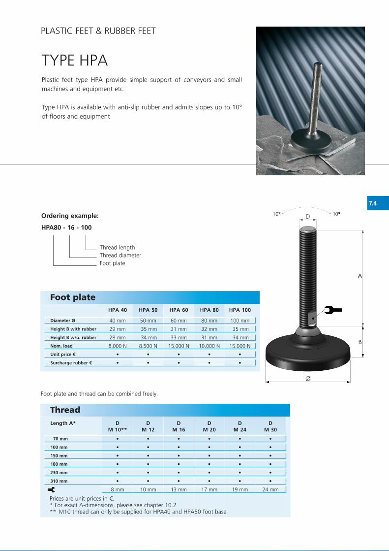
TyPE hPAPlastic feet type hPA provide simple support of conveyors and small machines and equipment etc.
Type hPA is available with anti-slip rubber and admits slopes up to 10° of floors and equipment
Ordering example:
HPA80 - 16 - 100
Thread lengthThread diameterfoot plate
Prices are unit prices in €.* for exact A-dimensions, please see chapter 10.2** M10 thread can only be supplied for hPA40 and hPA50 foot base
Foot plate
Diameter Ø
Height B with rubber
Height B w/o. rubber
Nom. load
Unit price €
Surcharge rubber €
ThreadLength A*
PLASTIC fEET & RUBBER fEET

7.5
HPA 81 HPA 101
80 mm 100 mm
32 mm 35 mm
31 mm 34 mm
28 mm 37 mm
9 mm 11 mm
10.000 N 15.000 N
DM 12
DM 16
DM 20
DM 24
D M 30
70 mm
100 mm
150 mm
180 mm
230 mm
310 mm
10 mm 13 mm 17 mm 19 mm 24 mm
• •
• •
• • • • •
• • • • •
• • • • •
• • • • •
• • • • •
• • • • •
foot plate and thread can be combined freely.
Ordering example:
HPA81 - 16 - 100
Thread lengthThread diameterfoot plate
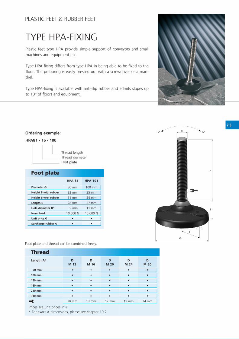
TyPE hPA-fIxINGPlastic feet type hPA provide simple support of conveyors and small machines and equipment etc.
Type hPA-fixing differs from type hPA in being able to be fixed to the floor. The preboring is easily pressed out with a screwdriver or a man-drel.
Type hPA-fixing is available with anti-slip rubber and admits slopes up to 10° of floors and equipment.
Prices are unit prices in €.* for exact A-dimensions, please see chapter 10.2
Foot plate
Diameter Ø
Height B with rubber
Height B w/o. rubber
Length E
Hole diameter D1
Nom. load
Unit price €
Surcharge rubber €
ThreadLength A*
PLASTIC fEET & RUBBER fEET

7.6
HPA 125(M20/M24)
HPA 125(M30/M36)
125 mm 125 mm
51 mm 43 mm
50 mm 42 mm
50 mm 50 mm
13 mm 13 mm
35.000 N 35.000 N
25.000 N 25.000 N
DM 16**
DM 20
DM 24
DM 30
DM 36
100 mm
150 mm
180 mm
230 mm
310 mm
17 mm 17 mm 19 mm 24 mm 30 mm
• • • • •
• • • • •
• • • • •
• • • • •
• • • • •
• •
• •
foot plate and thread can be combined freely.
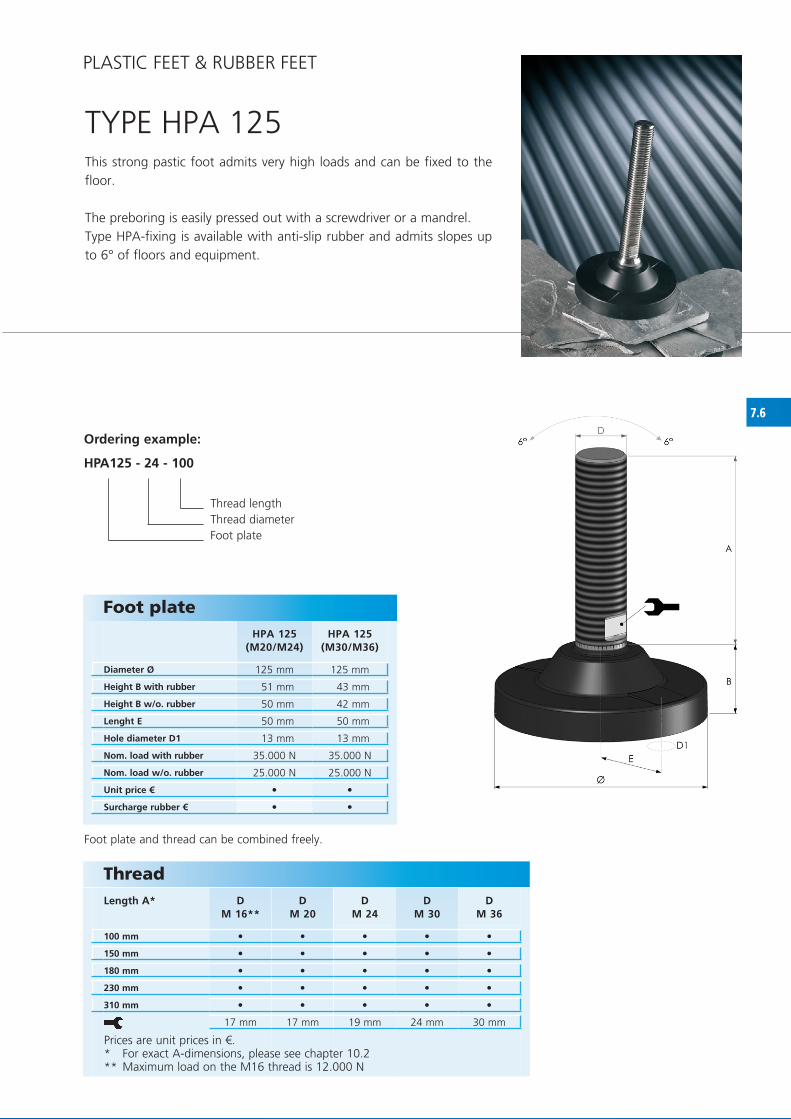
TyPE hPA 125This strong pastic foot admits very high loads and can be fixed to the floor.
The preboring is easily pressed out with a screwdriver or a mandrel. Type hPA-fixing is available with anti-slip rubber and admits slopes up to 6° of floors and equipment.
Ordering example:
HPA125 - 24 - 100
Thread length Thread diameter foot plate
Foot plate
Diameter Ø
Height B with rubber
Height B w/o. rubber
Lenght E
Hole diameter D1
Nom. load with rubber
Nom. load w/o. rubber
Unit price €
Surcharge rubber €
Thread Length A*
Prices are unit prices in €.* for exact A-dimensions, please see chapter 10.2** Maximum load on the M16 thread is 12.000 N
PLASTIC fEET & RUBBER fEET

7.7
B20-06-020 20 mm 6 mm 20 mm 13 mm 100 N
B25-08-020 25 mm 8 mm 20 mm 14 mm 150 N
B30-10-025 30 mm 10 mm 25 mm 16 mm 250 N
B30-10-050 30 mm 10 mm 50 mm 16 mm 250 N
B40-12-040 40 mm 12 mm 40 mm 20 mm 650 N
B40-12-070 40 mm 12 mm 70 mm 20 mm 650 N
B50-12-040 50 mm 12 mm 40 mm 20 mm 900 N
•
•
•
•
•
•
•
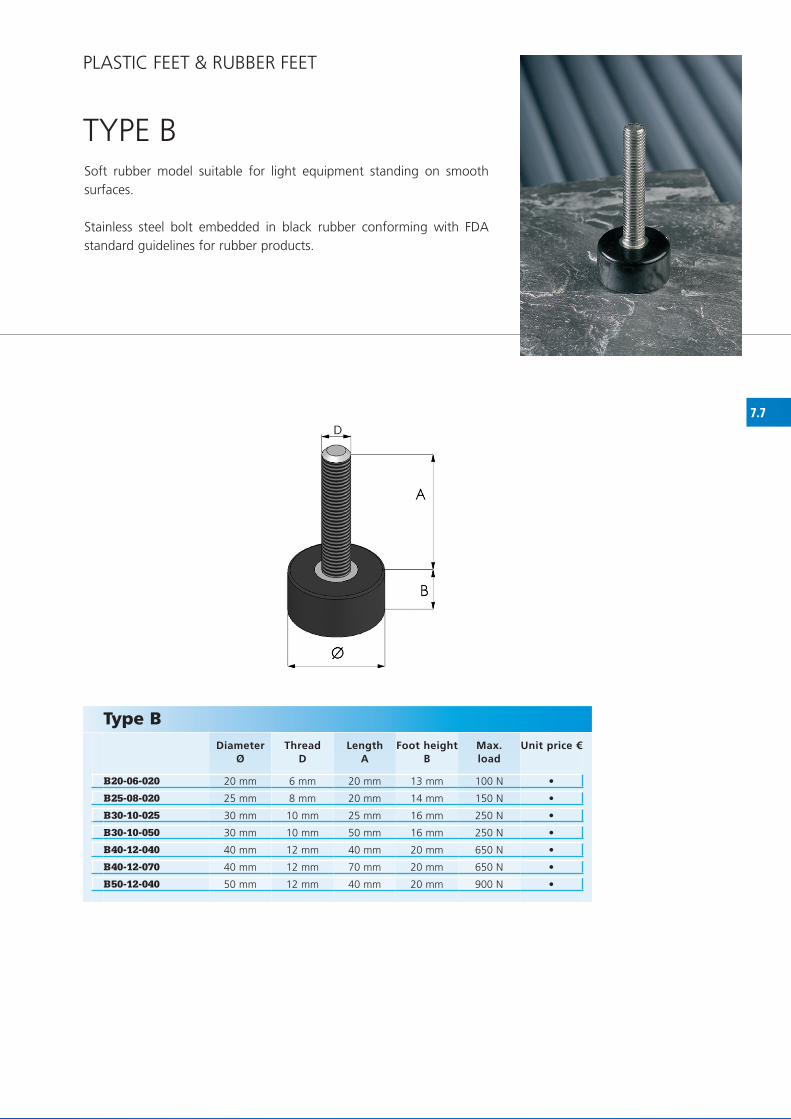
TyPE BSoft rubber model suitable for light equipment standing on smooth surfaces.
Stainless steel bolt embedded in black rubber conforming with fDA standard guidelines for rubber products.
Type B Diameter
ØThread
DLength
AFoot height
BMax.load
Unit price €
PLASTIC fEET & RUBBER fEET

7.8
S40-12-100 40 mm M 12 100 mm 23 mm 1.250 N
S50-16-100 50 mm M 16 100 mm 28 mm 2.000 N
S65-20-100 65 mm M 20 100 mm 35 mm 3.750 N
S80-20-100 80 mm M 20 100 mm 44 mm 6.000 N
S51-16-100 50 mm 16 mm 100 mm 27 mm 2.000 N
•
•
•
•
•
TyPE S / S51
Type S / S51 Diameter
ØThread
DLength
AFoot height
BMax.load
Unit price €
hole diameter D1: 11 mm. Length E: 52 mm.
Type S51
Type S51
Type S
Type S
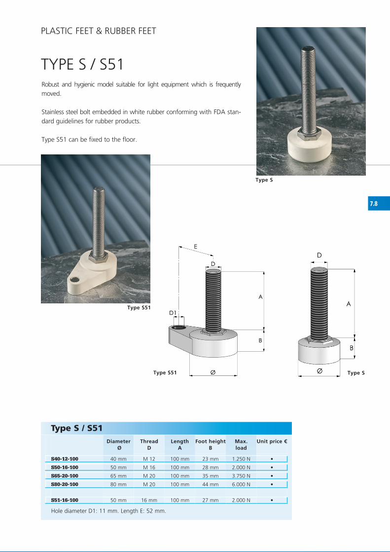
Robust and hygienic model suitable for light equipment which is frequently moved.
Stainless steel bolt embedded in white rubber conforming with fDA stan-dard guidelines for rubber products.
Type S51 can be fixed to the floor.
PLASTIC fEET & RUBBER fEET

8.1
3SB381 38,1 mm 10.000 N 80 mm 85 mm 145 mm 16 mm 224 mm 245 mm
3SB424 42,4 mm 10.000 N 80 mm 85 mm 145 mm 16 mm 224 mm 245 mm
3SB483 48,3 mm 10.000 N 80 mm 85 mm 145 mm 16 mm 224 mm 245 mm
3SB506 50,6 mm 10.000 N 80 mm 85 mm 145 mm 16 mm 224 mm 245 mm
3SB603 60,3 mm 10.000 N 80 mm 85 mm 145 mm 16 mm 224 mm 245 mm
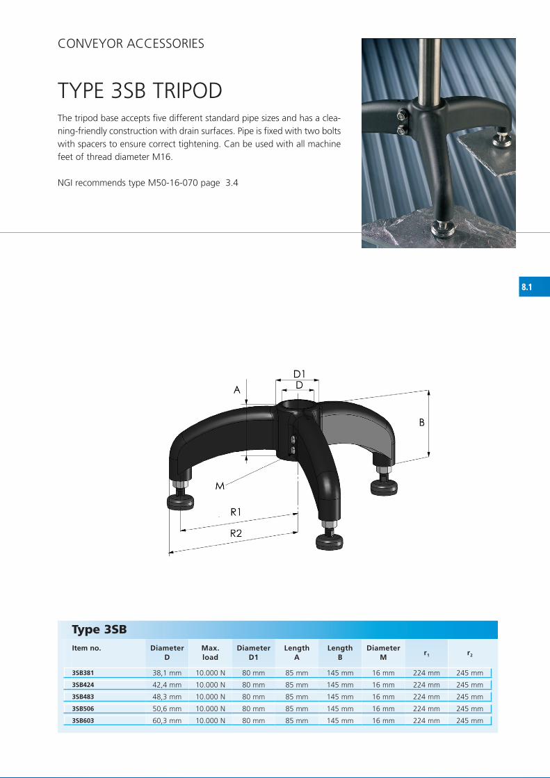
TyPE 3SB TRIPOD
Type 3SBItem no.
DiameterD
Max.load
DiameterD1
LengthA
LengthB
DiameterM
r1 r2
CONVEyOR ACCESSORIES
The tripod base accepts five different standard pipe sizes and has a clea-ning-friendly construction with drain surfaces. Pipe is fixed with two bolts with spacers to ensure correct tightening. Can be used with all machine feet of thread diameter M16.
NGI recommends type M50-16-070 page 3.4

8.2
2SB381 38,1 mm 9.600 N 80 mm 85 mm 145 mm 16 mm 224 mm 245 mm
2SB424 42,4 mm 9.600 N 80 mm 85 mm 145 mm 16 mm 224 mm 245 mm
2SB483 48,3 mm 9.600 N 80 mm 85 mm 145 mm 16 mm 224 mm 245 mm
2SB506 50,6 mm 9.600 N 80 mm 85 mm 145 mm 16 mm 224 mm 245 mm
2SB603 60,3 mm 9.600 N 80 mm 85 mm 145 mm 16 mm 224 mm 245 mm
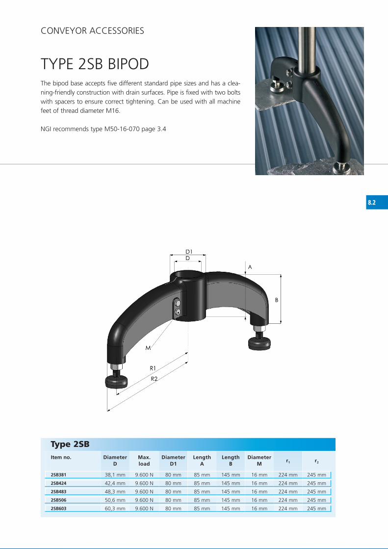
TyPE 2SB BIPOD
Type 2SBItem no.
DiameterD
Max.load
DiameterD1
LengthA
LengthB
DiameterM
r1 r2
CONVEyOR ACCESSORIES
The bipod base accepts five different standard pipe sizes and has a clea-ning-friendly construction with drain surfaces. Pipe is fixed with two bolts with spacers to ensure correct tightening. Can be used with all machine feet of thread diameter M16.
NGI recommends type M50-16-070 page 3.4

8.3
D M 8
DM 10
DM 12
DM 16
DM 20
DM 24
25 x 25 mm
30 x 30 mm
35 x 35 mm
40 x 40 mm
45 x 45 mm
50 x 50 mm
60 x 60 mm
70 x 70 mm
80 x 80 mm
100 x 100 mm
50 x 25 mm
50 x 30 mm
60 x 30 mm
60 x 40 mm
80 x 40 mm
80 x 50 mm
80 x 60 mm
100 x 50 mm
• • - - - -
• • • - - -
• • • • - -
• • • • • -
- • • • • -
- • • • • •
- - - • • •
- - - • • •
- - - • • •
- - - • • •
• • • - - -
• • • • - -
- - • • - -
- - • • • •
- - - • • •
- - - • • •
- - - • • •
- - - • • •
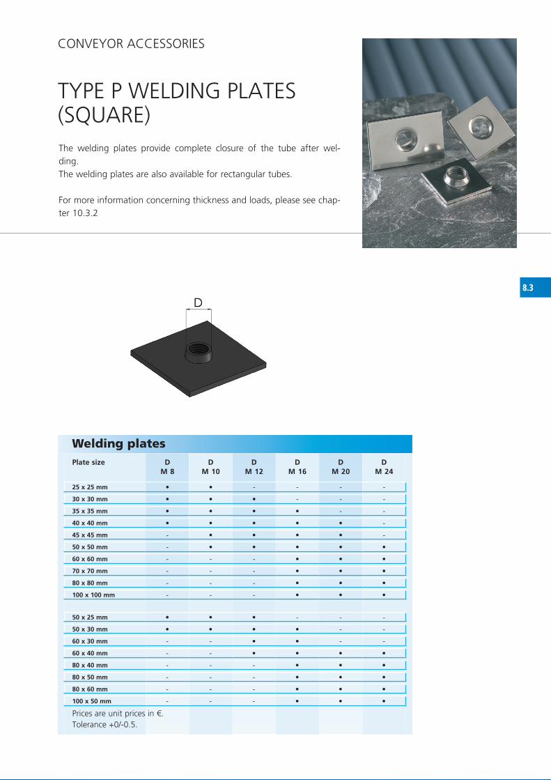
TyPE P WELDING PLATES(SQUARE)The welding plates provide complete closure of the tube after wel-ding.The welding plates are also available for rectangular tubes.
for more information concerning thickness and loads, please see chap-ter 10.3.2
CONVEyOR ACCESSORIES
Welding platesPlate size
Prices are unit prices in €.Tolerance +0/-0.5.


8.4
DM 8
DM 10
DM 12
DM 16
DM 20
DM 24
Ø33 mm
Ø38 mm
Ø40 mm
Ø43 mm
Ø50 mm
Ø60 mm
• • • - - -
• • • • - -
• • • • - -
- • • • • -
- • • • • •
- - - • • •
TyPE P WELDING PLATES(ROUND)The welding plates provide complete closure of the tube after wel-ding.
for more information concerning thickness and loads, please see chap-ter 10.3.3
CONVEyOR ACCESSORIES
Welding platesPlate size
Prices are unit prices in €.Tolerance +0/-0.5.

8.5
Ø C A A1 DM 16
DM 20
Ø 48,3 ø 45,3 52 mm 42 mm
Ø 60,3 ø 57,3 62 mm 52 mm
Ø 60,3 ø 55,3 62 mm 52 mm
D1 C A A1 DM 10
DM 12
DM 16
DM 20
30 x 30 mm 27 mm 33 mm 27 mm
40 x 40 mm 37 mm 43 mm 35 mm
40 x 40 mm 36 mm 43 mm 35 mm
50 x 50 mm 47 mm 55 mm 45 mm
50 x 50 mm 46 mm 55 mm 45 mm
50 x 50 mm 45 mm 55 mm 45 mm
• •
• •
• •
• • • -
• • • •
- - • •
- - • •
- - • •
- - • •
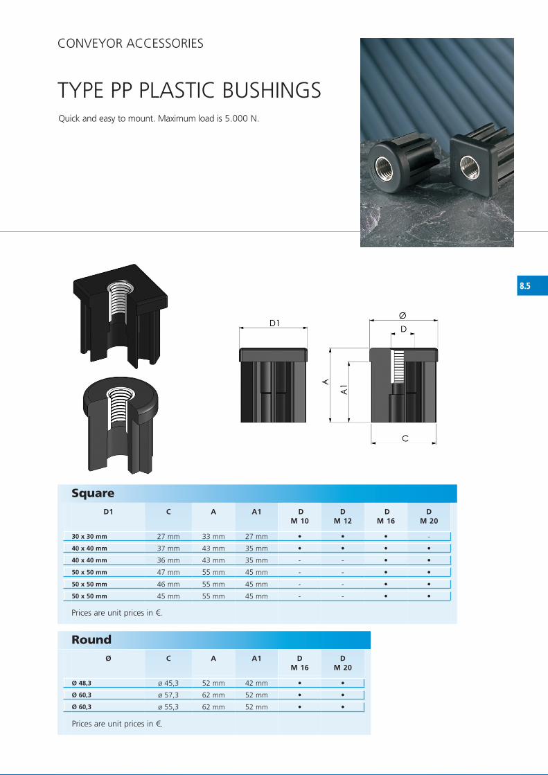
TyPE PP PLASTIC BUShINGSQuick and easy to mount. Maximum load is 5.000 N.
CONVEyOR ACCESSORIES
Round
Prices are unit prices in €.
Square
Prices are unit prices in €.

8.6
DM 10
DM 12
DM 16
DM 20
DM 24
DM 30
DM 10
DM 12
DM 16
DM 20
DM 24
DM 30
• • • • • •
• • • • • •
• • • • • •
• • • • - -
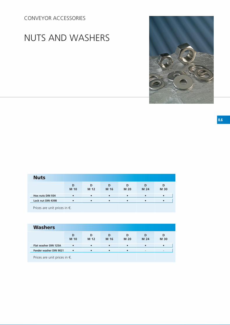
NUTS AND WAShERS
CONVEyOR ACCESSORIES
Nuts
Hex nuts DIN 934
Lock nut DIN 439B
Washers
Flat washer DIN 125A
Fender washer DIN 9021
Prices are unit prices in €.
Prices are unit prices in €.


9.1
STAINLESS STEEL PRODUCTSflexibility is an important concept to NGI, which is why we also offer customized solutions within machine feet and other rubber and metal products in stainless steel to our customers. It can be small adjustments to one of our standard products, or a completely different design or product that you might want to apply to your machines or equipment.Using the most modern software, our engineers can make 3D draw-ings, meaning that our offer gives you a satisfactory impression of the appearance of the product.
Please contact our sales deaprtment or send us a drawing or a sketch including your wishes, and we will treat your request as soon as pos-sible.
A selection of NGI customized products.
CUSTOMIZED PRODUCTS & TUBULAR CONSTRUCTIONS

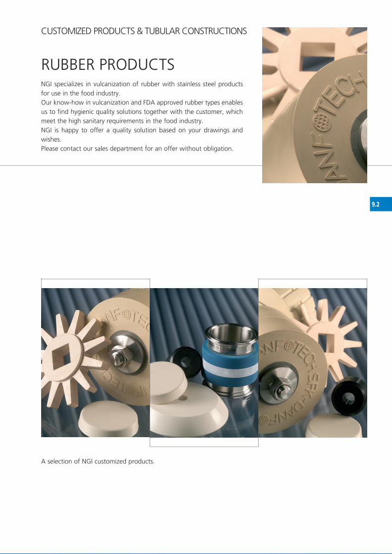
9.2
RUBBER PRODUCTSNGI specializes in vulcanization of rubber with stainless steel products for use in the food industry.Our know-how in vulcanization and fDA approved rubber types enables us to find hygienic quality solutions together with the customer, which meet the high sanitary requirements in the food industry.NGI is happy to offer a quality solution based on your drawings and wishes.Please contact our sales department for an offer without obligation.
A selection of NGI customized products.
CUSTOMIZED PRODUCTS & TUBULAR CONSTRUCTIONS

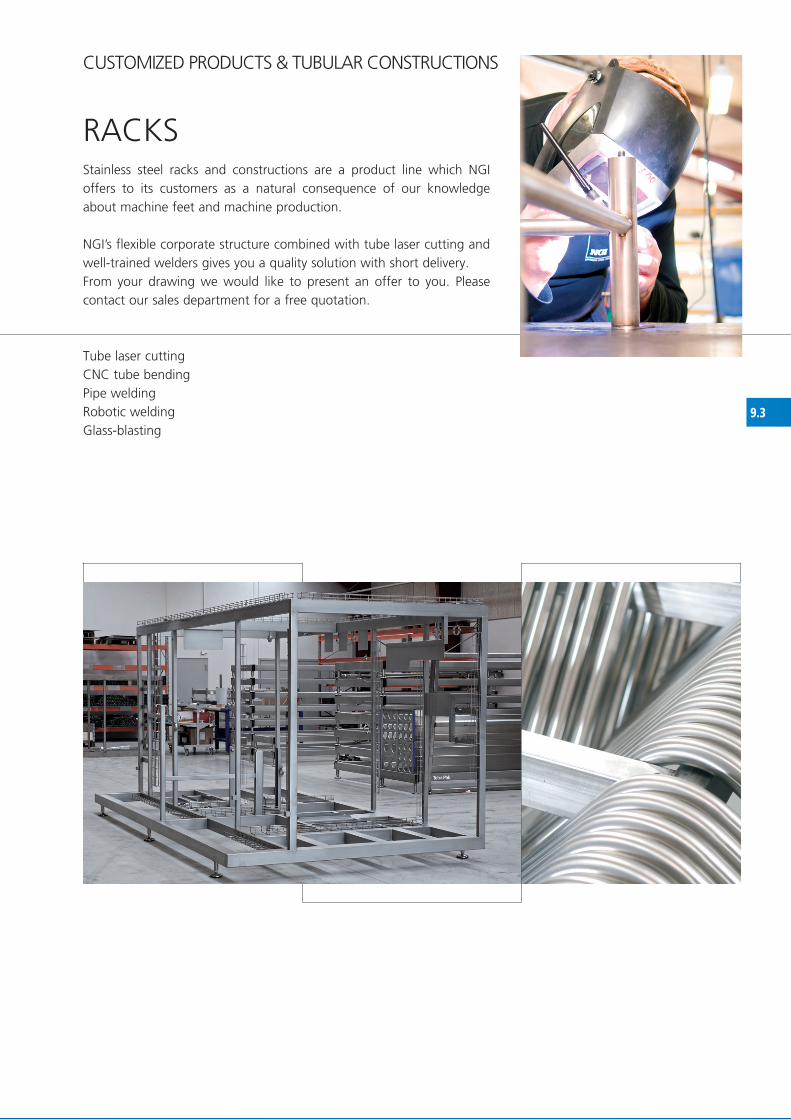
9.3
RACKSStainless steel racks and constructions are a product line which NGI offers to its customers as a natural consequence of our knowledge about machine feet and machine production.
NGI’s flexible corporate structure combined with tube laser cutting and well-trained welders gives you a quality solution with short delivery. from your drawing we would like to present an offer to you. Please contact our sales department for a free quotation.
Tube laser cutting CNC tube bending Pipe welding Robotic welding Glass-blasting
CUSTOMIZED PRODUCTS & TUBULAR CONSTRUCTIONS

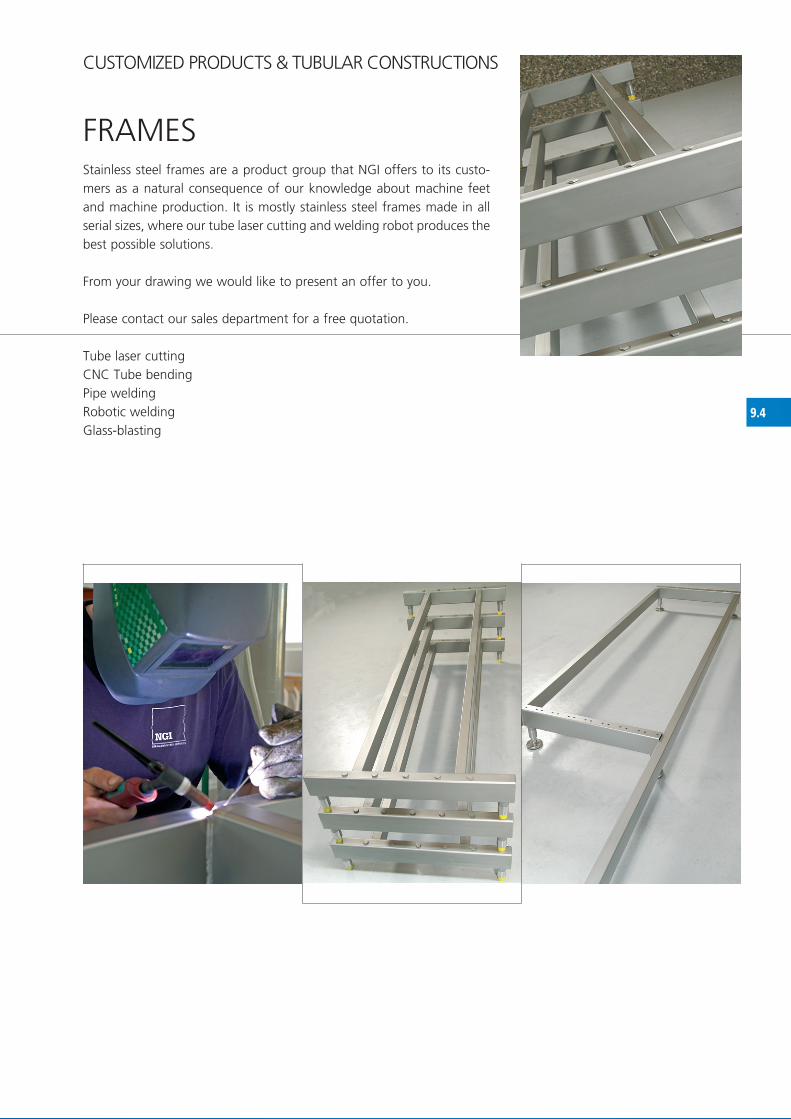
9.4
fRAMESStainless steel frames are a product group that NGI offers to its custo-mers as a natural consequence of our knowledge about machine feet and machine production. It is mostly stainless steel frames made in all serial sizes, where our tube laser cutting and welding robot produces the best possible solutions.
from your drawing we would like to present an offer to you.
Please contact our sales department for a free quotation. Tube laser cutting CNC Tube bending Pipe welding Robotic welding Glass-blasting
CUSTOMIZED PRODUCTS & TUBULAR CONSTRUCTIONS

10.1
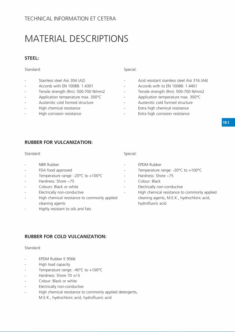
STEEL:
Standard:
- Stainless steel Aisi 304 (A2) - Accords with EN 10088: 1.4301- Tensile strength (Rm): 500-700 N/mm2- Application temperature max. 300°C- Austenitic cold formed structure- high chemical resistance- high corrosion resistance
Special:
- Acid resistant stainless steel Aisi 316 (A4) - Accords with to EN 10088: 1.4401- Tensile strength (Rm): 500-700 N/mm2- Application temperature max. 300°C- Austenitic cold formed structure- Extra high chemical resistance- Extra high corrosion resistance
RUBBER FOR VULCANIZATION:
Standard:
- NBR Rubber- fDA food approved- Temperature range: -20°C to +100°C- hardness: Shore ~75- Colours: Black or white- Electrically non-conductive- high chemical resistance to commonly applied cleaning agents- highly resistant to oils and fats
Special:
- EPDM Rubber- Temperature range: -20°C to +100°C- hardness: Shore ~75- Colour: Black - Electrically non-conductive- high chemical resistance to commonly applied cleaning agents, M.E.K., hydrochloric acid, hydrofluoric acid
RUBBER FOR COLD VULCANIZATION:
Standard:
- EPDM Rubber E 9566- high load capacity- Temperature range: -40°C to +100°C- hardness: Shore 70 +/-5- Colour: Black or white- Electrically non-conductive- high chemical resistance to commonly applied detergents, M.E.K., hydrochloric acid, hydrofluoric acid
MATERIAL DESCRIPTIONS
TEChNICAL INfORMATION ET CETERA

10.1.1
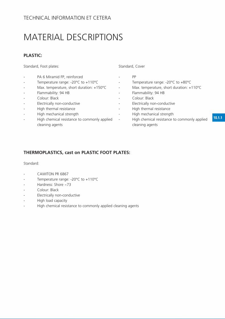
PLASTIC:
Standard, foot plates:
- PA 6 Miramid fP, reinforced- Temperature range: -20°C to +110°C- Max. temperature, short duration: +150°C- flammability: 94 hB- Colour: Black - Electrically non-conductive- high thermal resistance- high mechanical strength- high chemical resistance to commonly applied cleaning agents
Standard, Cover
- PP- Temperature range: -20°C to +80°C- Max. temperature, short duration: +110°C- flammability: 94 hB- Colour: Black - Electrically non-conductive- high thermal resistance- high mechanical strength- high chemical resistance to commonly applied cleaning agents
THERMOPLASTICS, cast on PLASTIC FOOT PLATES:
Standard:
- CAWITON PR 6867 - Temperature range: -20°C to +110°C- hardness: Shore ~73- Colour: Black - Electrically non-conductive - high load capacity - high chemical resistance to commonly applied cleaning agents
MATERIAL DESCRIPTIONS
TEChNICAL INfORMATION ET CETERA

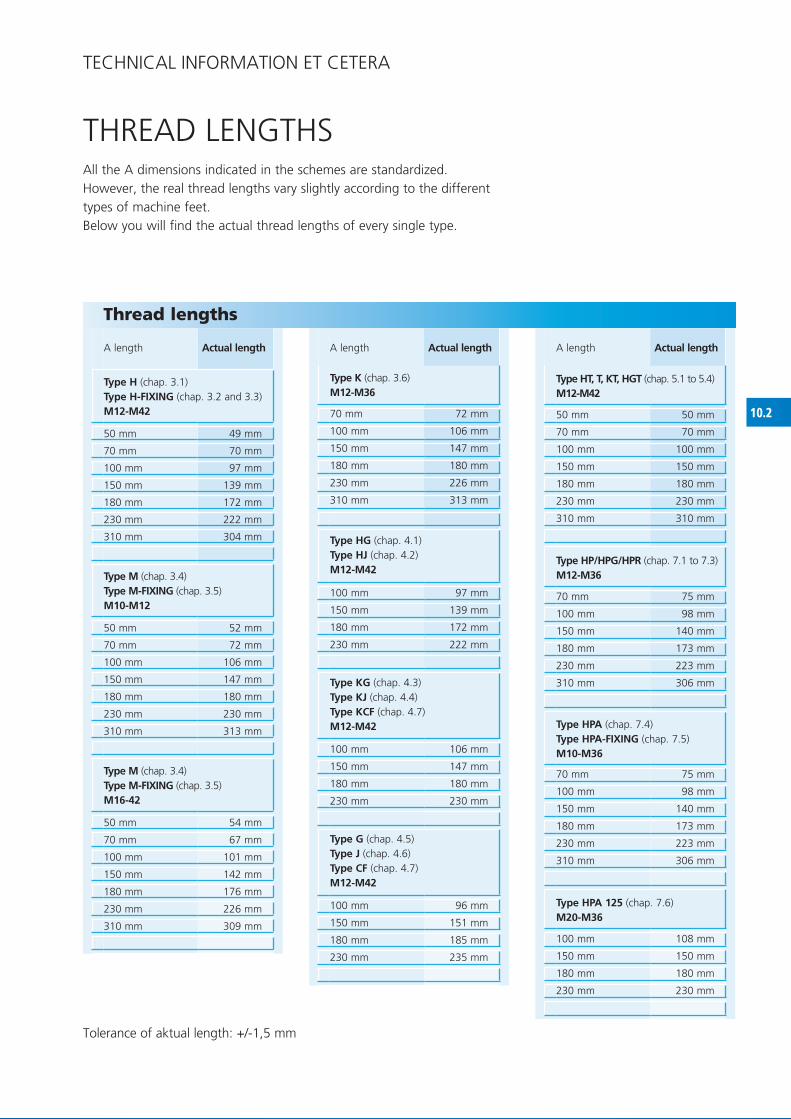
10.2
50 mm 49 mm
70 mm 70 mm
100 mm 97 mm
150 mm 139 mm
180 mm 172 mm
230 mm 222 mm
310 mm 304 mm
50 mm 52 mm
70 mm 72 mm
100 mm 106 mm
150 mm 147 mm
180 mm 180 mm
230 mm 230 mm
310 mm 313 mm
50 mm 54 mm
70 mm 67 mm
100 mm 101 mm
150 mm 142 mm
180 mm 176 mm
230 mm 226 mm
310 mm 309 mm
70 mm 72 mm
100 mm 106 mm
150 mm 147 mm
180 mm 180 mm
230 mm 226 mm
310 mm 313 mm
100 mm 97 mm
150 mm 139 mm
180 mm 172 mm
230 mm 222 mm
100 mm 106 mm
150 mm 147 mm
180 mm 180 mm
230 mm 230 mm
100 mm 96 mm
150 mm 151 mm
180 mm 185 mm
230 mm 235 mm
50 mm 50 mm
70 mm 70 mm
100 mm 100 mm
150 mm 150 mm
180 mm 180 mm
230 mm 230 mm
310 mm 310 mm
70 mm 75 mm
100 mm 98 mm
150 mm 140 mm
180 mm 173 mm
230 mm 223 mm
310 mm 306 mm
70 mm 75 mm
100 mm 98 mm
150 mm 140 mm
180 mm 173 mm
230 mm 223 mm
310 mm 306 mm
100 mm 108 mm
150 mm 150 mm
180 mm 180 mm
230 mm 230 mm
ThREAD LENGThS
TEChNICAL INfORMATION ET CETERA
All the A dimensions indicated in the schemes are standardized.however, the real thread lengths vary slightly according to the different types of machine feet.Below you will find the actual thread lengths of every single type.
Tolerance of aktual length: +/-1,5 mm
Thread lengths
A length Actual length
Type H (chap. 3.1) Type H-FIXING (chap. 3.2 and 3.3)M12-M42
Type M (chap. 3.4)Type M-FIXING (chap. 3.5) M10-M12
Type M (chap. 3.4)Type M-FIXING (chap. 3.5)M16-42
A length Actual length
Type K (chap. 3.6)M12-M36
Type HG (chap. 4.1)Type HJ (chap. 4.2)M12-M42
Type KG (chap. 4.3)Type KJ (chap. 4.4)Type KCF (chap. 4.7)M12-M42
Type G (chap. 4.5)Type J (chap. 4.6)Type CF (chap. 4.7)M12-M42
A length Actual length
Type HT, T, KT, HGT (chap. 5.1 to 5.4)M12-M42
Type HP/HPG/HPR (chap. 7.1 to 7.3) M12-M36
Type HPA (chap. 7.4)Type HPA-FIXING (chap. 7.5)M10-M36
Type HPA 125 (chap. 7.6)M20-M36

10.3
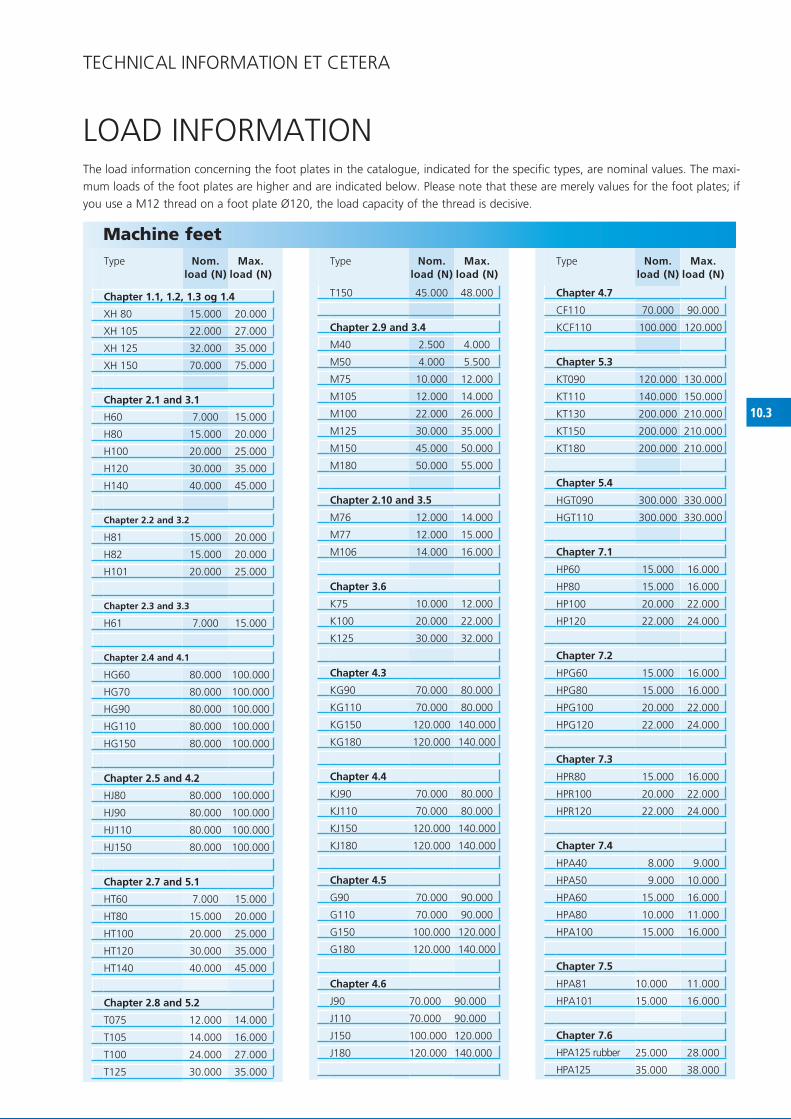
xh 80 15.000 20.000
xh 105 22.000 27.000
xh 125 32.000 35.000
xh 150 70.000 75.000
h60 7.000 15.000
h80 15.000 20.000
h100 20.000 25.000
h120 30.000 35.000
h140 40.000 45.000
h81 15.000 20.000
h82 15.000 20.000
h101 20.000 25.000
h61 7.000 15.000
hG60 80.000 100.000
hG70 80.000 100.000
hG90 80.000 100.000
hG110 80.000 100.000
hG150 80.000 100.000
hJ80 80.000 100.000
hJ90 80.000 100.000
hJ110 80.000 100.000
hJ150 80.000 100.000
hT60 7.000 15.000
hT80 15.000 20.000
hT100 20.000 25.000
hT120 30.000 35.000
hT140 40.000 45.000
T075 12.000 14.000
T105 14.000 16.000
T100 24.000 27.000
T125 30.000 35.000
T150 45.000 48.000
M40 2.500 4.000
M50 4.000 5.500
M75 10.000 12.000
M105 12.000 14.000
M100 22.000 26.000
M125 30.000 35.000
M150 45.000 50.000
M180 50.000 55.000
M76 12.000 14.000
M77 12.000 15.000
M106 14.000 16.000
K75 10.000 12.000
K100 20.000 22.000
K125 30.000 32.000
KG90 70.000 80.000
KG110 70.000 80.000
KG150 120.000 140.000
KG180 120.000 140.000
KJ90 70.000 80.000
KJ110 70.000 80.000
KJ150 120.000 140.000
KJ180 120.000 140.000
G90 70.000 90.000
G110 70.000 90.000
G150 100.000 120.000
G180 120.000 140.000
J90 70.000 90.000
J110 70.000 90.000
J150 100.000 120.000
J180 120.000 140.000
Cf110 70.000 90.000
KCf110 100.000 120.000
KT090 120.000 130.000
KT110 140.000 150.000
KT130 200.000 210.000
KT150 200.000 210.000
KT180 200.000 210.000
hGT090 300.000 330.000
hGT110 300.000 330.000
hP60 15.000 16.000
hP80 15.000 16.000
hP100 20.000 22.000
hP120 22.000 24.000
hPG60 15.000 16.000
hPG80 15.000 16.000
hPG100 20.000 22.000
hPG120 22.000 24.000
hPR80 15.000 16.000
hPR100 20.000 22.000
hPR120 22.000 24.000
hPA40 8.000 9.000
hPA50 9.000 10.000
hPA60 15.000 16.000
hPA80 10.000 11.000
hPA100 15.000 16.000
hPA81 10.000 11.000
hPA101 15.000 16.000
25.000 28.000
35.000 38.000
LOAD INfORMATION
TEChNICAL INfORMATION ET CETERA
The load information concerning the foot plates in the catalogue, indicated for the specific types, are nominal values. The maxi-mum loads of the foot plates are higher and are indicated below. Please note that these are merely values for the foot plates; if you use a M12 thread on a foot plate Ø120, the load capacity of the thread is decisive.
Machine feetType Nom.
load (N)Max.
load (N)
Chapter 1.1, 1.2, 1.3 og 1.4
Chapter 2.1 and 3.1
Chapter 2.2 and 3.2
Chapter 2.3 and 3.3
Chapter 2.4 and 4.1
Chapter 2.5 and 4.2
Chapter 2.7 and 5.1
Chapter 2.8 and 5.2
Type Nom. load (N)
Max. load (N)
Chapter 2.9 and 3.4
Chapter 2.10 and 3.5
Chapter 3.6
Chapter 4.3
Chapter 4.4
Chapter 4.5
Chapter 4.6
Type Nom. load (N)
Max. load (N)
Chapter 4.7
Chapter 5.3
Chapter 5.4
Chapter 7.1
Chapter 7.2
Chapter 7.3
Chapter 7.4
Chapter 7.5
Chapter 7.6
hPA125 rubber
hPA125

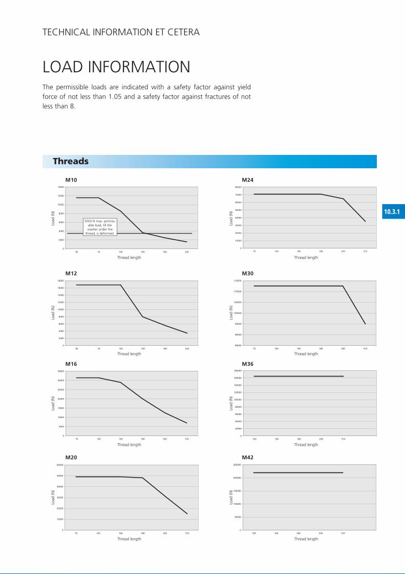
10.3.1
0
2000
4000
6000
8000
10000
12000
14000
50 70 100 150 180 230
0
2000
4000
6000
8000
10000
12000
14000
16000
18000
50 70 100 150 180 230
0
5000
10000
15000
20000
25000
30000
35000
70 100 150 180 230 310
0
10000
20000
30000
40000
50000
60000
70 100 150 180 230 310
0
10000
20000
30000
40000
50000
60000
70000
80000
70 100 150 180 230 310
85000
90000
95000
100000
105000
110000
115000
70 100 150 180 230 310
0
20000
40000
60000
80000
100000
120000
140000
160000
180000
100 150 180 230 310
0
50000
100000
150000
200000
250000
100 150 180 230 310
LOAD INfORMATION
TEChNICAL INfORMATION ET CETERA
Threads
The permissible loads are indicated with a safety factor against yield force of not less than 1.05 and a safety factor against fractures of not less than 8.
M10
M16
M24
M36
M12
M20
M30
M42
Thread length
Thread length
3500 N max. permiss-able load, till the washer under the
thread, is deformed.
Load
(N)
Load
(N)
Load
(N)
Load
(N)
Load
(N)
Load
(N)
Load
(N)
Load
(N)
Thread length
Thread length
Thread length
Thread length
Thread length
Thread length

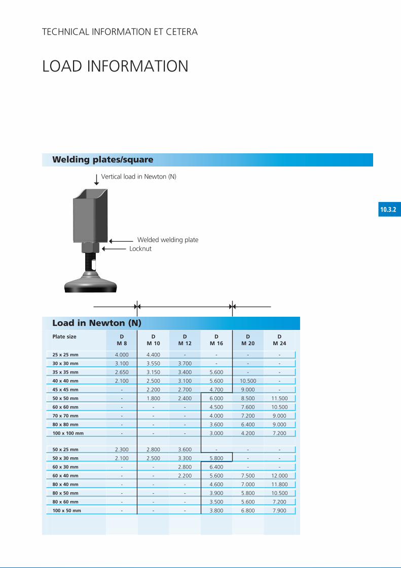
10.3.2
D M 8
DM 10
DM 12
DM 16
DM 20
DM 24
25 x 25 mm 4.000 4.400 - - - -
30 x 30 mm 3.100 3.550 3.700 - - -
35 x 35 mm 2.650 3.150 3.400 5.600 - -
40 x 40 mm 2.100 2.500 3.100 5.600 10.500 -
45 x 45 mm - 2.200 2.700 4.700 9.000 -
50 x 50 mm - 1.800 2.400 6.000 8.500 11.500
60 x 60 mm - - - 4.500 7.600 10.500
70 x 70 mm - - - 4.000 7.200 9.000
80 x 80 mm - - - 3.600 6.400 9.000
100 x 100 mm - - - 3.000 4.200 7.200
50 x 25 mm 2.300 2.800 3.600 - - -
50 x 30 mm 2.100 2.500 3.300 5.800 - -
60 x 30 mm - - 2.800 6.400 - -
60 x 40 mm - - 2.200 5.600 7.500 12.000
80 x 40 mm - - - 4.600 7.000 11.800
80 x 50 mm - - - 3.900 5.800 10.500
80 x 60 mm - - - 3.500 5.600 7.200
100 x 50 mm - - - 3.800 6.800 7.900
LOAD INfORMATION
Welding plates/square
Load in Newton (N)Plate size
Vertical load in Newton (N)
Welded welding plateLocknut
TEChNICAL INfORMATION ET CETERA

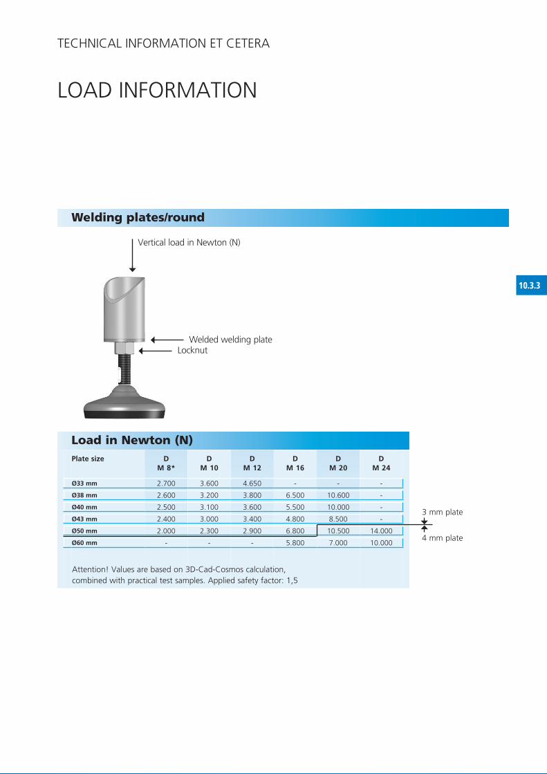
10.3.3
DM 8*
DM 10
DM 12
DM 16
DM 20
DM 24
Ø33 mm 2.700 3.600 4.650 - - -
Ø38 mm 2.600 3.200 3.800 6.500 10.600 -
Ø40 mm 2.500 3.100 3.600 5.500 10.000 -
Ø43 mm 2.400 3.000 3.400 4.800 8.500 -
Ø50 mm 2.000 2.300 2.900 6.800 10.500 14.000
Ø60 mm - - - 5.800 7.000 10.000
LOAD INfORMATION
Welding plates/round
Vertical load in Newton (N)
Welded welding plateLocknut
TEChNICAL INfORMATION ET CETERA
Load in Newton (N)Plate size
Attention! Values are based on 3D-Cad-Cosmos calculation,combined with practical test samples. Applied safety factor: 1,5
3 mm plate
4 mm plate

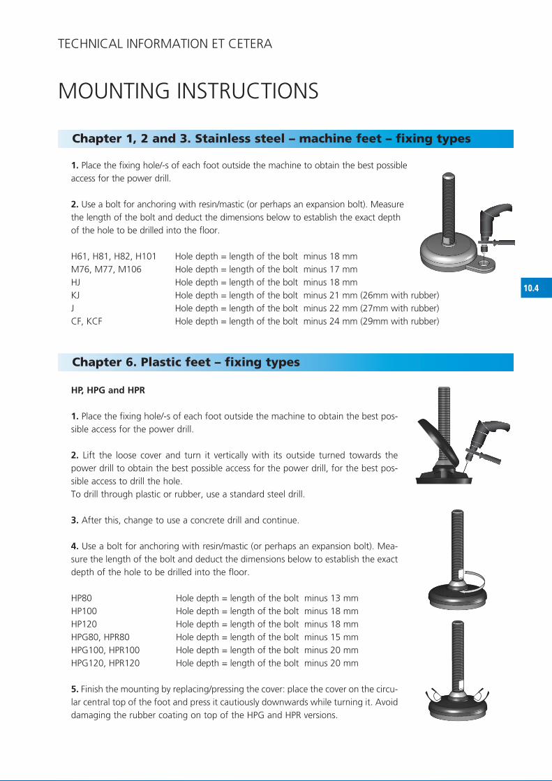
10.4
MOUNTING INSTRUCTIONS
TEChNICAL INfORMATION ET CETERA
1. Place the fixing hole/-s of each foot outside the machine to obtain the best possible access for the power drill.
2. Use a bolt for anchoring with resin/mastic (or perhaps an expansion bolt). Measure the length of the bolt and deduct the dimensions below to establish the exact depth of the hole to be drilled into the floor.
h61, h81, h82, h101 hole depth = length of the bolt minus 18 mmM76, M77, M106 hole depth = length of the bolt minus 17 mm hJ hole depth = length of the bolt minus 18 mm KJ hole depth = length of the bolt minus 21 mm (26mm with rubber)J hole depth = length of the bolt minus 22 mm (27mm with rubber)Cf, KCf hole depth = length of the bolt minus 24 mm (29mm with rubber)
Chapter 1, 2 and 3. Stainless steel – machine feet – fixing types
HP, HPG and HPR
1. Place the fixing hole/-s of each foot outside the machine to obtain the best pos-sible access for the power drill.
2. Lift the loose cover and turn it vertically with its outside turned towards the power drill to obtain the best possible access for the power drill, for the best pos-sible access to drill the hole.To drill through plastic or rubber, use a standard steel drill.
3. After this, change to use a concrete drill and continue.
4. Use a bolt for anchoring with resin/mastic (or perhaps an expansion bolt). Mea-sure the length of the bolt and deduct the dimensions below to establish the exact depth of the hole to be drilled into the floor.
hP80 hole depth = length of the bolt minus 13 mmhP100 hole depth = length of the bolt minus 18 mmhP120 hole depth = length of the bolt minus 18 mmhPG80, hPR80 hole depth = length of the bolt minus 15 mmhPG100, hPR100 hole depth = length of the bolt minus 20 mmhPG120, hPR120 hole depth = length of the bolt minus 20 mm
5. finish the mounting by replacing/pressing the cover: place the cover on the circu-lar central top of the foot and press it cautiously downwards while turning it. Avoid damaging the rubber coating on top of the hPG and hPR versions.
Chapter 6. Plastic feet – fixing types

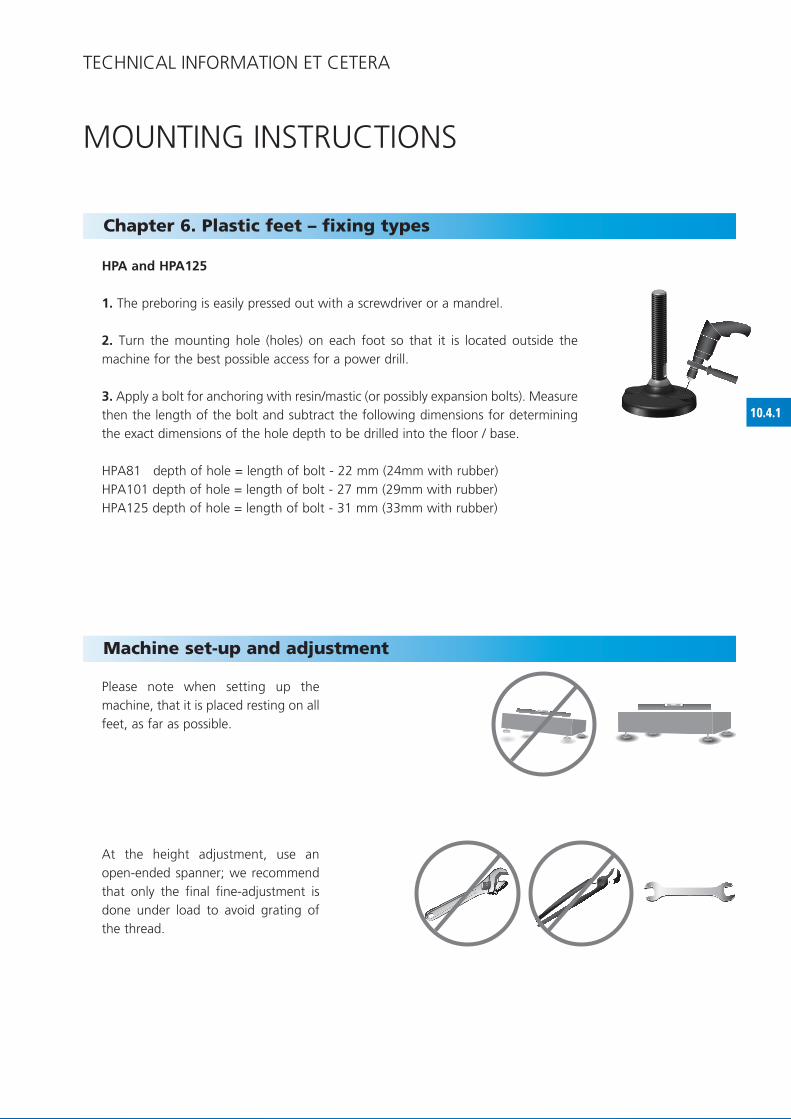
10.4.1
Please note when setting up the machine, that it is placed resting on all feet, as far as possible.
At the height adjustment, use an open-ended spanner; we recommend that only the final fine-adjustment is done under load to avoid grating of the thread.
Machine set-up and adjustment
HPA and HPA125
1. The preboring is easily pressed out with a screwdriver or a mandrel.
2. Turn the mounting hole (holes) on each foot so that it is located outside the machine for the best possible access for a power drill.
3. Apply a bolt for anchoring with resin/mastic (or possibly expansion bolts). Measure then the length of the bolt and subtract the following dimensions for determining the exact dimensions of the hole depth to be drilled into the floor / base.
hPA81 depth of hole = length of bolt - 22 mm (24mm with rubber) hPA101 depth of hole = length of bolt - 27 mm (29mm with rubber) hPA125 depth of hole = length of bolt - 31 mm (33mm with rubber)
Chapter 6. Plastic feet – fixing types
MOUNTING INSTRUCTIONS
TEChNICAL INfORMATION ET CETERA

10.5
CLEANING INSTRUCTIONSThe cleaning effort (the time) to be used for cleaning NGI’s machine feet depends largely on what kind of machine foot, you buy and on the kind of environment in which the machine foot is placed. Below you will find the instructions for cleaning effort: low / medium / high according to the type of machine foot and according to the environment. you can use all known detergents and disinfectants to clean NGI’s machine feet. It is recommended that you carefully follow the instructions enclosed of the detergents from the providers.
TEChNICAL INfORMATION ET CETERA
Cleaning instructions/advice
PHARMA AND CLEANROOM
DAIRY AND BREwERY
MEAT AND BAKERY
PACKAGING-MACHINE ETC.
Cleaningeffort Cleaningeffort Cleaningeffort Cleaningeffort
LOw
MED
IUM
HIG
H
LOw
MED
IUM
HIG
H
LOw
MED
IUM
HIG
H
LOw
MED
IUM
HIG
H
NGI Stainless Steel Machine feet EHEDG & 3A
XH / XHF
XHT / XHTF
NGI Stainless Steel Machine feet HYGIENIC (USDA)
H hyGIENIC / HT hyGIENIC
HG hyGIENIC / HJ hyGIENIC / HGT hyGIENIC
M hyGIENIC / T hyGIENIC
NGI Stainless Steel Machine feet
H / HT / STAINLESS STEEL SOLID HG / HJ / HGT
M
K / STAINLESS STEEL SOLID J / G / KJ / KG
NGI Plastic feet and Rubber feet
HP / HPG / HPR / RUBBER fEET B / S
HPA / HPA125
Kan anvendes med angivne rengøringsindsats
Kan delvis anvendes med angivne rengøringsindsats
Kan ikke anvendes uanset rengøringsindsats

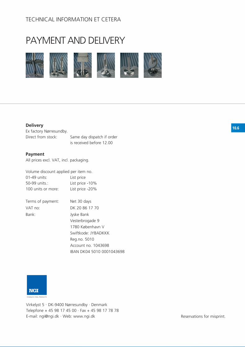
10.6
NGISTAINLESS STEEL PRODUCTS
DeliveryEx factory Nørresundby.Direct from stock: Same day dispatch if order
is received before 12.00
PaymentAll prices excl. VAT, incl. packaging.
Volume discount applied per item no.01-49 units: List price50-99 units.: List price -10%100 units or more: List price -20%
Terms of payment: Net 30 days
VAT no: DK 20 86 17 70
Bank: Jyske Bank
Vesterbrogade 9
1780 København V
Swiftkode: JyBADKKK
Reg.no. 5010
Account no. 1043698
IBAN DK04 5010 0001043698
Reservations for misprint.
Virkelyst 5 · DK-9400 Nørresundby · Denmark Telepfone + 45 98 17 45 00 · fax + 45 98 17 78 78 E-mail: [email protected] · Web: www.ngi.dk
PAyMENT AND DELIVERy
TEChNICAL INfORMATION ET CETERA

10.7
1.0 Scope of application of terms and conditions of sales and delivery1.1 The current terms and conditions of sales and delivery apply to all NGI A/S offers, sales and deliveries unless agreed to the contrary in writing.1.2 final agreement of delivery is first entered into on the purchaser’s receipt of NGI A/S written confirmation of order and only the content of the confirmation of order applies to NGI A/S.
2.0 Delivery and dispatch2.1 Delivery takes place ex factory from NGI A/S, Virkelyst 5, 9400 Nørresundby, Denmark, directly from store including packaging.2.2 Orders which are received by NGI A/S before 13.00 Danish time (12.00 GMT) are dispatched the same day unless expressly agreed to the contrary.
3.0 Terms of payment3.1 Payment must be made at latest by the date stated as the last punctual payment day on the invoices sent by NGI A/S.3.2 If payment is made after the due date NGI A/S is entitled to charge interest on the outstanding amount from the due date at a rate of 2% per started month.
4.0 Liability, defects and delays4.1 NGI A/S is obliged to rectify all defects due to imperfections in construction, material or production by making repairs or replacement of the delivery according to points 4.2 - 4.12.4.2 NGI A/S liability only includes defects which appear within one year from the day of taking possession of the delivered goods. If the delivered goods are used more intensively than agreed or more intensively than presupposed on entering into the agreement, this period is shortened proportionally.4.3 for parts of the delivery which are repaired or exchanged in accordance with point 4.1 NGI has the same obligations which apply to the original delivery for a period of one year. for the remainder of the delivered goods the period men-tioned in point 4.2 is only prolonged by the period of time in which the delivery has not been applicable because of defects, dealt with in point 4.14.4 The purchaser must report a defect to NGI A/S in writing and without unreasonable delay following discovery of the defect. The message must contain a description of how the defect manifests itself.If there is reason to believe that the defect can cause risk of damage, such a message must be given immediately.If the purchaser does not inform NGI A/S in writing about a defect within the period of time stated in this point, the purchaser foregoes the right to make demands in connection with the defect.4.5 On receipt of a written message with reference to point 4.4 NGI A/S must rectify the defect without unreasonable delay. NGI A/S must bear the costs of rectification with reference to the stipulations in points 4.1 - 4.12.Rectification of the defect shall be carried out at the place of installation, unless NGI A/S finds it suitable for the defective part or materials to be returned so that NGI A/S can make repairs at NGI A/S’s premises or provide a replacement.NGI A/S obligation concerning the defective part is fulfilled when NGI A/S has delivered a duly repaired or exchanged part to the purchaser.4.6 If the purchaser has given such a message as mentioned in point 4.4, and it transpires that there is no defect for which NGI A/S carries responsibility, NGI A/S has the right to remuneration for work done and the costs which the claim has caused to NGI A/S. 4.7 If possible demounting and installation necessitates intervention in other things than the delivered goods, the work and the costs hereby incurred are carried by the purchaser.4.8 Any dispatch in connection with repair or exchange shall take place at NGI A/S expense and risk. The purchaser must
TERMS Of SALE AND DELIVERy
TEChNICAL INfORMATION ET CETERA

10.7.1
follow NGI A/S instructions concerning despatch.The purchaser must carry the extra costs which are caused to NGI A/S when rectifying defects if the delivered goods are in another place than the place of installation.4.9 Defective parts which are exchanged with reference to point 4.1 must be placed at NGI A/S disposal and become NGI A/S’s property.4.10 If NGI A/S has not fulfilled its obligations within a reasonable time according to point 4.5, the purchaser can give NGI A/S in writing a last opportunity to do so. If the obligations are not fulfilled within the determined time, the purchaser is entitled to:a) let the necessary repairs be carried out and/or have new parts made at NGI A/S expense and risk, provided that the purchaser does this in a sensible and reasonable way orb) demand a proportional discount up to a maximum 15% of the contract sum.If the defect is essential, the purchaser can alternatively cancel the agreement in writing to NGI A/S. The purchaser also has the right to thus cancel the agreement if the defect, following the steps mentioned under point a) still remains essential. On cancellation the purchaser can demand compensation for the loss up to a maximum 15% of the contract sum.4.11 NGI A/S’s liability does not include defects caused by material which is provided by the purchaser, by constructions which are prescribed or specified by the purchaser or by faulty preparatory work on the purchaser’s side.4.12 NGI A/S’s liability only includes defects which appear under those in the agreement’s presupposed working conditi-ons and under correct use of the delivered goods.The liability does not include defects caused by circumstances occurring after taking over possession of the delivered goods. It does not for example include defects which are caused by defective maintenance on the purchaser’s side, or changes to the delivered goods made by the purchaser without NGI A/S’s written consent or repairs which the purchaser has carried out in a faulty manner. The liability does not include normal wear and tear and depreciation.4.13 NGI A/S has no liability for defects besides those described in points 4.1 - 4.12. This applies to any loss which the defect might cause, including loss on operations, lost earnings and other financial consequence loss. This limitation of NGI A/S’s liability does not apply if NGI A/S is guilty of gross negligence.
5.0 Liability for damage caused by the delivered goods after taking possession (product liability) 5.1 The purchaser shall indemnify NGI A/S to the extent that NGI A/S has imposed liability to a third party for such damage and such loss which NGI A/S according this point’s second and third sections is not liable to the purchaser.NGI A/S is not responsible for damage caused by the delivered goods after possession has been taken:a) on real property or movables which occurs while the delivered goods are in the purchaser’s possession.b) on products which are produced by the purchaser, or on products where these form a part, or on damage to real property or movables which these products cause due to the delivered goods.In no case is NGI A/S responsible for operational loss, lost earnings or other financial consequence loss.The stated limitations in NGI A/S’s liability do not apply if NGI A/S is guilty of gross negligence.If a third party makes a demand on one of the parties concerning liability to pay compensation with reference to this point, this party must immediately inform the other party.
6.0 Venue6.1 Disagreement between the parties must be ruled on according to Danish law and with Sø- og handelsretten in Copenhagen as the venue.
TEChNICAL INfORMATION ET CETERA
TERMS Of SALE AND DELIVERy