
Stabilization loop of a two axes gimbal system using self...
12
Research Article Stabilization loop of a two axes gimbal system using self-tuning PID type fuzzy controller Maher Mahmoud Abdo a,n , Ahmad Reza Vali a , Ali Reza Toloei b , Mohammad Reza Arvan a a Malek Ashtat University of Technology, Department of Electrical Engineering, Lavizan, Tehran, Iran b Shahid Behechti University, Department of Aerospace, Tehran, Iran article info Article history: Received 29 June 2013 Received in revised form 17 November 2013 Accepted 3 December 2013 Available online 22 January 2014 This paper was recommended for publicaton by A.B. Rad Keywords: Gimbal system Line of sight Rate gyro Inertia stabilization system Stabilization loop abstract The application of inertial stabilization system is to stabilize the sensor's line of sight toward a target by isolating the sensor from the disturbances induced by the operating environment. The aim of this paper is to present two axes gimbal system. The gimbals torque relationships are derived using Lagrange equation considering the base angular motion and dynamic mass unbalance. The stabilization loops are constructed with cross coupling unit utilizing proposed fuzzy PID type controller. The overall control system is simulated and validated using MATLAB. Then, the performance of proposed controller is evaluated comparing with conventional PI controller in terms of transient response analysis and quantitative study of error analysis. The simulation results obtained in different conditions prove the efficiency of the proposed fuzzy controller which offers a better response than the classical one, and improves further the transient and steady-state performance. & 2013 ISA. Published by Elsevier Ltd. All rights reserved. 1. Introduction The optical equipments (such as IR, radar, laser, and television) have found a wide use in many important applications, for example image processing, guided missiles, tracking systems, and navigation systems. In such systems, the optical sensor axis must be accurately pointed from a movable base to a fixed or moving target. Therefore, the sensor's line of sight (LOS) must be strictly controlled. In such an environment where the equipment is typically mounted on a movable platform, maintaining sensor orientation toward a target is a serious challenge. An Inertial Stabilization Platform (ISP) is an appropriate way that can solve this challenge [1]. Usually, two axes gimbal system is used to provide stabilization to the sensor while different disturbances affect it. The most important disturbance sources are the base angular motion, the dynamics of gimballed system, and the gimbal mass unbalance. It is therefore necessary to capture all the dynamics of the plant and express the plant in analytical form before the design of gimbal assembly is taken up [2]. The system performance depends heavily on the accuracy of plant modelling. A typical plant for such problems consists of an electro-mechanical gimbal assembly having angular freedom in one, two or three axes and one or more electro-optical sensors [3]. The control of such LOS inertia stabilization systems is not a simple problem because of cross-couplings between the different channels. In addition, such systems are usually required to maintain stable operation and guarantee accurate pointing and tracking for the target even when there are changes in the system dynamics and operational condi- tions. The mathematical model and the control system of two axes gimbal system have been studied in many researches. Concerning the mathematical model, several derivations have been proposed using different assumptions. In [4], the kinematics and geometrical coupling relationships for two degree of freedom gimbal assembly have been obtained for a simplified case when each gimbal is balanced and the gimballed elements bodies are suspended about principal axes. [5] presented the equations of motion for two axes gimbal configuration, assuming that gimbals are rigid bodies and have no mass unbalance. In [5], Ekstrand has shown that inertia disturbances can be eliminated by certain inertia symmetry conditions, and certain choices of inertia parameters can eliminate the inertia cross couplings between gimbal system channels. A single degree of freedom gimbal operating in a complex vibration environment has been presented by Daniel in [6]. He illustrated how the vibrations excite both static and dynamic unbalance disturbance torques that can be eliminated by statically and dynamically balancing the gimbal which is regarded costly and time consuming [6]. In [7], the motion equations have been derived assuming that gimbals have no dynamic mass imbalance and without highlighting the effects of base angular velocities. Contents lists available at ScienceDirect journal homepage: www.elsevier.com/locate/isatrans ISA Transactions 0019-0578/$ - see front matter & 2013 ISA. Published by Elsevier Ltd. All rights reserved. http://dx.doi.org/10.1016/j.isatra.2013.12.008 n Corresponding author. Tel.: þ98 937 750 4893. E-mail addresses: [email protected] (M.M. Abdo), [email protected] (A.R. Vali), [email protected] (A.R. Toloei), [email protected] (M.R. Arvan). ISA Transactions 53 (2014) 591–602 Downloaded from http://www.elearnica.ir
Transcript of Stabilization loop of a two axes gimbal system using self...

Research Article
Stabilization loop of a two axes gimbal system using self-tuningPID type fuzzy controller
Maher Mahmoud Abdo a,n, Ahmad Reza Vali a, Ali Reza Toloei b, Mohammad Reza Arvan a
a Malek Ashtat University of Technology, Department of Electrical Engineering, Lavizan, Tehran, Iranb Shahid Behechti University, Department of Aerospace, Tehran, Iran
a r t i c l e i n f o
Article history:Received 29 June 2013Received in revised form17 November 2013Accepted 3 December 2013Available online 22 January 2014This paper was recommended forpublicaton by A.B. Rad
Keywords:Gimbal systemLine of sightRate gyroInertia stabilization systemStabilization loop
a b s t r a c t
The application of inertial stabilization system is to stabilize the sensor's line of sight toward a target byisolating the sensor from the disturbances induced by the operating environment. The aim of this paperis to present two axes gimbal system. The gimbals torque relationships are derived using Lagrangeequation considering the base angular motion and dynamic mass unbalance. The stabilization loops areconstructed with cross coupling unit utilizing proposed fuzzy PID type controller. The overall controlsystem is simulated and validated using MATLAB. Then, the performance of proposed controller isevaluated comparing with conventional PI controller in terms of transient response analysis andquantitative study of error analysis. The simulation results obtained in different conditions prove theefficiency of the proposed fuzzy controller which offers a better response than the classical one, andimproves further the transient and steady-state performance.
& 2013 ISA. Published by Elsevier Ltd. All rights reserved.
1. Introduction
The optical equipments (such as IR, radar, laser, and television)have found a wide use in many important applications, forexample image processing, guided missiles, tracking systems,and navigation systems. In such systems, the optical sensor axismust be accurately pointed from a movable base to a fixed ormoving target. Therefore, the sensor's line of sight (LOS) must bestrictly controlled. In such an environment where the equipmentis typically mounted on a movable platform, maintaining sensororientation toward a target is a serious challenge. An InertialStabilization Platform (ISP) is an appropriate way that can solvethis challenge [1]. Usually, two axes gimbal system is used toprovide stabilization to the sensor while different disturbancesaffect it. The most important disturbance sources are the baseangular motion, the dynamics of gimballed system, and the gimbalmass unbalance. It is therefore necessary to capture all thedynamics of the plant and express the plant in analytical formbefore the design of gimbal assembly is taken up [2]. The systemperformance depends heavily on the accuracy of plant modelling.A typical plant for such problems consists of an electro-mechanicalgimbal assembly having angular freedom in one, two or three axes
and one or more electro-optical sensors [3]. The control of suchLOS inertia stabilization systems is not a simple problem becauseof cross-couplings between the different channels. In addition,such systems are usually required to maintain stable operation andguarantee accurate pointing and tracking for the target even whenthere are changes in the system dynamics and operational condi-tions. The mathematical model and the control system of two axesgimbal system have been studied in many researches. Concerningthe mathematical model, several derivations have been proposedusing different assumptions. In [4], the kinematics and geometricalcoupling relationships for two degree of freedom gimbal assemblyhave been obtained for a simplified case when each gimbal isbalanced and the gimballed elements bodies are suspended aboutprincipal axes. [5] presented the equations of motion for two axesgimbal configuration, assuming that gimbals are rigid bodies andhave no mass unbalance. In [5], Ekstrand has shown that inertiadisturbances can be eliminated by certain inertia symmetryconditions, and certain choices of inertia parameters can eliminatethe inertia cross couplings between gimbal system channels.A single degree of freedom gimbal operating in a complexvibration environment has been presented by Daniel in [6]. Heillustrated how the vibrations excite both static and dynamicunbalance disturbance torques that can be eliminated by staticallyand dynamically balancing the gimbal which is regarded costlyand time consuming [6]. In [7], the motion equations have beenderived assuming that gimbals have no dynamic mass imbalanceand without highlighting the effects of base angular velocities.
Contents lists available at ScienceDirect
journal homepage: www.elsevier.com/locate/isatrans
ISA Transactions
0019-0578/$ - see front matter & 2013 ISA. Published by Elsevier Ltd. All rights reserved.http://dx.doi.org/10.1016/j.isatra.2013.12.008
n Corresponding author. Tel.: þ98 937 750 4893.E-mail addresses: [email protected] (M.M. Abdo),
[email protected] (A.R. Vali), [email protected] (A.R. Toloei),[email protected] (M.R. Arvan).
ISA Transactions 53 (2014) 591–602
Downloaded from http://www.elearnica.ir

In [8], a two axes gimbal mechanism was introduced and just themodelling of azimuth axis was focused while the elevation anglewas kept fixed and cross moments of inertia were taken to be zero.In both [5,9], the dynamical model of elevation and azimuthgimbals have been derived on the assumption that gimbals massdistribution is symmetrical so the products of inertia wereneglected and the model was simplified. It must be mentioned,that most of these researches considered that the elevation andazimuth channels are identical so that one axis was simulated andtested. Therefore, the cross coupling, which is caused by baseangular motion and the properties of gimbal system dynamics,was ignored. Also, it was supposed that gimbals mass distributionis symmetrical so the gimbals have not dynamic unbalance.In addition, Newton's law has been utilized to derive the mathe-matical model. On the other hand, the control system of two axesgimbal configuration has been constructed using different controlapproaches. In [7], a proxy-based sliding mode has been appliedon two axes gimbal system; also [10] proposed the sliding modecontrol under the assumption of uncoupled identical elevation andazimuth channels. In [11], modern synthesis tools such as linearquadratic regulator (LQR) or linear quadratic Gaussian with looptransfer recovery (LQG/LTR) control for a wideband controller havealso been used in the line of sight stabilization for mobile landvehicle. Also, [12] presented a linear quadratic Gaussian (LQG)algorithm for estimating and compensating in real time a parti-cular class of disturbances. Besides conventional control methods,some advance control techniques such as robust control [13],variable structure control (VSC) [14], and H1 control methodology[15] were also applied in LOS inertia stabilization systems. How-ever, a majority of these algorithms were complex and difficult tobe realized. In recent years, the fuzzy control technology has beendeveloped successfully. It improves the control system perfor-mance, and has the good adaptability for the system with non-linear mathematical model and uncertain factors [16,17]. Unlikethe conventional control, the fuzzy logic control usually does notneed the accurate mathematical model of the process which mustbe controlled and therefore fuzzy logic is considered one of thebest solves for wide section of stubborn and challenging controlproblems [18,19]. There are two types of fuzzy logic-basedcontrollers; Takagi Sugeno (T–S) based and Mamdani based. Inliterature, it can be found that almost all nonlinear dynamicalsystems can be represented by Takagi Sugeno fuzzy models to highdegree of precision. In fact, it is proved that Takagi-Sugeno fuzzymodels are universal approximators of any smooth nonlinearsystem [20]. When the fuzzy logic system is incorporated intoadaptive control scheme, a stable fuzzy adaptive controller isobtained to be used in complex environments that imposeperturbations on plant parameters. In such environments, thiscontroller is used online to modify and adjust the control para-meters automatically [17]. Basically, the adaptive fuzzy controllershave been developed for unknown SISO and MIMO nonlinearsystems but they are limited only to nonlinear systems whosestates can be measured [21]. A fuzzy control system was imple-mented in [22] to control inertial rate of LOS. [23] Introduced anefficient full-matrix fuzzy logic controller for a gyro mirror line-of-sight stabilization platform. A fuzzy logic based controller andadaptive-neuro fuzzy inference system (ANFIS) have been pre-sented in [19–24] for speed control of DC servo motor. In [25],a comparative study of PID, ANFIS, and hybrid-PID ANFIS con-trollers has been accomplished for the speed control of brushlessdirect current motor. In this paper, a self-tuning PID-type fuzzytechnique is introduced for a two axes gimbal system which itsmathematical model is completely derived using Lagrange equa-tion considering the cross coupling between two channels, thedynamic unbalance, and the base angular velocities. The controlaims are mainly to achieve good transient and steady-state
performance with respect to step input commands. The contribu-tions of this paper can be summarized as follows. The completemodel of two axes gimbal system is derived assuming that gimbalshave mass unbalance as well as considering all inertia distur-bances and cross coupling. Then, an applicable adaptive fuzzycontroller is designed utilizing simple tuning algorithm which canconsiderably reduce the overshoot without significant increase inthe rise time value. The paper is organized in the followingmanner. In Section 2, the problem is formulated and the equationsof gimbals motion are derived in Section 3. Afterwards, thestabilization loop is investigated and constructed in Section 4.Then, in Section 5 the proposed fuzzy controller is designed. Thesimulation results are introduced in Section 6. Finally, the conclu-sion remarks are highlighted in Section 7.
2. Problem formulation
The stabilization is usually provided to the sensor by suspend-ing it on the inner gimbal of two axes gimbal system as shown inFig. 1 [26]. A rate gyro located on the inner gimbal is utilized tomeasure the angular rates in the two planes of interest. The gyrooutputs are used as feedback to torque motors related to thegimbals to provide boresight error tracking and stabilizationagainst base angular motion. The overall control system is con-structed utilizing two identical stabilization loops (Fig. 2) for theinner (elevation) and outer (azimuth) gimbals. The control systemof two axes gimbal system attempts to align the sensor optical axisin elevation and azimuth planes with a line joining the sensor andtarget which is called the line of sight (LOS) so that the sensoroptical axis is kept nonrotating in an inertial space despite torquedisturbances which affect the elevation and azimuth gimbals andbasically caused by the base angular motions which are usuallyimposed by the operating environment. Therefore, the stabiliza-tion loop must isolate the sensor from the angular base motionand disturbances that disturb the aim-point, i.e. the output rates ofstabilization loops must follow certain input rate commands sothat the rate error is made zero. According to Newton's first andsecond laws, all that is required to prevent an object (sensor) fromrotating with respect to inertial space is to ensure that the applied
Body A
Body B
platform
Pitch axis
Yaw axis
e
rd
i
j
k
e n
k
n
r
Gimbalpointingdirection
ηη
ε
ε
Fig. 1. Two axes gimbal system [23].
Torque disturbanc
Totaltorque
LOS rateMotortorqueRate
error
Ratecommand
controller DC motor Inertia
Rate gyro
++−+
Fig. 2. One axis gimbal stabilization loop.
M.M. Abdo et al. / ISA Transactions 53 (2014) 591–602592

torque is zero [27]. However, even in well designed and carefulelectromechanical systems, the operating environment createsnumerous sources of torque disturbances that affect on a realmechanism making extreme motion or jitter of line of sight [27].In such environments, as all control systems, the gimbal controlsystem suffers from problems related to undesirable overshoot,longer settling times and vibrations, and stability. In order toovercome these problems, the gimbal system control loops will bedeveloped using adaptive PID-type fuzzy controller. The elevationand azimuth control loops are related by the cross coupling unitwhich is built based on the relationships of torques affect thegimbals. The cross coupling express the properties of the gimbalsystem dynamics and reflects the fact that azimuth gimbal canaffect on elevation gimbal even when base body is nonrotating.Also, there is similar impact from elevation gimbal on azimuthgimbal. As a result, the cross coupling is defined as the effect onone axis by the rotation of another [6]. In this paper, the model oftwo axes gimbal system is obtained and simulated considering thedynamic mass unbalance which is the result of a non-symmetricalmass distribution called Product of Inertia (POI) [6]. The dynamicmass unbalance concept can be indicated by the inertia matrix.If the gimbal has a symmetrical mass distribution with respect toits frame axes, so the gimbal has no dynamic mass unbalance andits inertia matrix is diagonal and vice versa.
3. Equations of gimbals motion
In this paper, a two axes gimbal system depicted in Fig. 1 isconsidered. Three reference frames are identified; frame P fixed tofuselage body with axes (i,j,k), frame B fixed to azimuth gimbalwith axes (n,e,k), and frame A fixed to elevation gimbal with axes(r,e,d). The r-axis coincides with the sensor optical axis. The k axisis pointing “downwards”. The rotation center is at the frameorigin, which is assumed to be the same point for three frames.The transformation matrices in terms of rotation angles ε, η
BPC ¼
cos η sin η 0� sin η cos η 0
0 0 1
264
375; A
BC ¼cos ε 0 � sin ε0 1 0
sin ε 0 cos ε
264
375 ð1Þ
where BPC is the transformation from frame P to frame B. Similarly,
ABC is the transformation from frame B to frame A. The inertialangular velocity vectors of frames P, B, and A, respectively are
pω,
P=I ¼ωpi
ωpj
ωpk
264
375; Bω
,B=I ¼
ωBn
ωBe
ωBK
264
375; Aω
,A=I ¼
ωAr
ωAe
ωAd
264
375 ð2Þ
where ωpi ; ωpj ; ωpk are the body angular velocities of frame P inrelation to inertial space about i, j, and k axes respectively,ωBn ; ωBe ; ωBk are the azimuth gimbal angular velocities in rela-tion to inertial space about n, e, and k axes, respectively, andωAr ; ωAe ; ωAd
are the elevation gimbal angular velocities inrelation to inertial space about the r, e, and d axes, respectively.Inertia matrices of elevation and azimuth gimbals are
AJ inner ¼Ar Are Ard
Are Ae Ade
Ard Ade Ad
264
375; BJouter ¼
Bn Bne Bnk
Bne Be Bke
Bnk Bke Bk
264
375 ð3Þ
where Ar, Ae, Ad are elevation gimbal moments of inertia about r, e,and d axes, Are, Ard, Ade are elevation gimbal moments products ofinertia, Bn, Be, Bk are azimuth gimbal moments of inertia about n, e,and k axes, and Bne, Bnk, Bke are azimuth gimbal moments productsof inertia. Also, it is introduced TEL as the total external torqueabout the elevation gimbal e-axis, and TAZ as the total externaltorque about the azimuth gimbal k-axis. As mentioned above, the
aim is to stabilize the gimbal system LOS (r-axis), i.e. the outputrates of stabilization loops ωAe,ωAd, which can be measured bya rate gyro placed on the elevation gimbal, must follow the inputrate commands ωEL,ωAZ. In general, Euler angles define theposition between two related reference frames [28]. For frames Pand B utilizing the angle η, then between azimuth gimbal frame Band elevation gimbal frame A utilizing the angle ε, the followingrelations can be respectively obtained.
Eq:a : ωBn ¼ωPi cos ηþωPj sin η;
Eq:b : ωBe ¼ �ωPi sin ηþωPj cos η;
Eq:c : ωBK ¼ωPkþ _η ð4Þ
Eq:a : ωAr ¼ωBn cos ε�ωBK sin ε;
Eq:b : ωAe ¼ωBeþ _ε;
Eq:c : ωAd ¼ωBn sin εþωBk cos ε ð5Þ
The orientation of the gimbal system in an inertial system iscompletely determined by four independent consecutive rotationsϕ, θ, ψ, ε where ϕ, θ, ψ are Euler rotations of the azimuth gimbaland ε is elevation gimbal angle [5]. Then, rotation angles can betaken as generalized coordinates in Lagrange equations. Therotations order is essential [5]. Fig. 3 shows the order of con-secutive Euler rotations of azimuth gimbal. By taking the rotationsin the order roll (ϕ), elevation (θ), and azimuth (ψ) followed by ε,the generalized “forces” corresponding to the coordinates ψ and εare the external torques TAZ and TEL applied to azimuth andelevation gimbals, respectively [5]. The kinetic energy T of rotatingbody is given by the scalar product (T ¼ω� ðH=2Þ; H ¼ Jω); whereH the angular momentum, ω the body inertial rate expressed inthe body fixed frame, and J the body inertia matrix. Thus the totalkinetic energy of two axes gimbal system is the sum of kineticenergy of elevation and azimuth gimbals.
T ¼ω� H2
�����A
þω� H2
�����B
¼ 12ðArω2
ArþAeω2AeþAdω2
AdÞ
þAreωArωAeþArdωArωAdþAdeωAeωAdþ12ðBnω2
BnþBeω2BeþBkω2
BkÞ
þBneωBnωBeþBnkωBnωBkþBkeωBeωBk ð6Þ
.
Fig. 3. Azimuth gimbal angular velocities.
M.M. Abdo et al. / ISA Transactions 53 (2014) 591–602 593

Based on Fig. 3, the azimuth gimbal angular velocities can bederived as follows
ωBn ¼ _ϕ cos θ cos ψþ _θ sin ψ ;
ωBe ¼ � _ϕ cos θ sin ψþ _θ cos ψ ; ωBk ¼ _ϕ sin θþ _ψ ð7Þ
Using (7) and (5) in (6) give the kinetic energy as a function ofthe generalized coordinates and their time derivatives. Thus,Lagrange equation can be formulated utilizing T from (6) andequations of motion are obtained. The complete derivation ofazimuth relationships is illustrated in Appendix A. Lagrangeequation for ψ is
ddt
∂T∂ _ψ
� �� ∂T∂ψ
¼ TAZ ð8Þ
The equation of azimuth gimbal motion can be derived asa differential equation for ωBk as follows
Jeq _ωBk ¼ TAzþTd1þTd2þTd3; Td ¼ Td1þTd2þTd3 ð9Þ
After some mathematical operations, Eq. (9) can be convertedto a differential equation for ωAd as follows
Jeq _ωAd ¼ TAz cos εþTd cos εþT 0d ð10Þ
In [5], Eq. (9) has been simplified assuming that gimbals haveno dynamic mass unbalance i.e. (Are¼Ard¼Ade¼Bne¼Bnk¼Bke¼0)as well as applying other choices of inertia parameters (Ar¼Ad,BnþAr¼Be). Therefore in [5], the disturbances Td have beenreduced to one term (AeωBnωAe). Thus, Eq. (9) becomes
Jeq _ωBk ¼ TAz�AeωBnωAe ð11Þ
Also, the complete derivation of elevation relationships isillustrated in Appendix B. Lagrange equation for ε is
ddt
∂T∂ _ε
� ��∂T∂ε
¼ TEL ð12Þ
The elevation gimbal motion equation is obtained as a differ-ential equation for the elevation rate ωAe as follows
Ae _ωAe ¼ TELþðAd�ArÞωArωAd
þArdðω2Ar�ω2
AdÞ �Adeð _ωAd�ωAeωArÞ �Areð _ωArþωAeωAdÞð13Þ
In [5], Eq. (13) has been simplified by eliminating all distur-bances assuming that elevation gimbal has no dynamic massunbalance, i.e. (Are¼Ard¼Ade¼0 and Ar¼Ad). Therefore, Eq. (13)becomes as follows
Ae _ωAe ¼ TEL ð14ÞFig. 4. Simplified two axes gimbal torque relationships introduced in [5].
Fig. 5. Complete two axes gimbal torque relationships (cross coupling unit).
M.M. Abdo et al. / ISA Transactions 53 (2014) 591–602594

Based on (11) and (14), the simplified model obtained in [5] isindicated in Fig. 4. While utilizing Eqs. (10), (A.10), (A.11), (A.12) ofazimuth channel in addition to Eqs. (13), (B.4),…, (B.14) of eleva-tion channel, the complete torque relationships of two axes gimbalsystem introduced in this work is presented in Fig. 5.
Concerning cross coupling, the elevation disturbances (B.3) canbe divided into two parts TD�EL¼TB�ELþTC�EL where
TB�EL ¼ �ðAde sin εþAre cos εÞð _ωBnþωBeωBkÞþðAde cos ε�Are sin εÞωBnωBe
þ½ðAd�ArÞ cos ð2εÞ�2Ard sin ð2εÞ�ωBnωBk
þ12½ðAd�ArÞ sin ð2εÞþ2Ard cos ð2εÞ�ω2
Bn ð15Þ
TC�EL ¼ ðAre sin ε�Ade cos εÞ _ωBk�12½ðAd�ArÞ sin ð2εÞþ2Ard cos ð2εÞ�ω2
Bk
ð16ÞIt can be seen that the azimuth gimbal may affects the
elevation gimbal irrespective of the base body motions becauseeven when the base is nonrotating i.e., ωpi¼ωpj¼ωpk¼0 the termTB�EL is absolutely zero because from (4) we haveωBn¼ωBe¼0 butωBk and consequently the term TC�EL is not necessarily zero.Therefore, the term TC�EL is the elevation cross coupling term.Similarly, the disturbances of azimuth channel Td¼Td1þTd2þTd3can be divided into two parts Td¼TB�AZþTC�AZ. Applying the samediscussion above, the term TC�AZ is the azimuth cross couplingterm which expresses the effect of elevation gimbal on theazimuth gimbal even when the base is nonrotating.
TB�AZ ¼ Td1þTd2þ½ðAr�AdÞ cos ð2εÞþ2Ard sin ð2εÞ�Ae�_εωBn
þ½ðAr�AdÞ sin ð2εÞ�2Ard cos ð2εÞ�ωBeωBk
þðAde cos ε�Are sin εÞ _ωBe�ðAde sin εþAre cos εÞω2Be
ð17Þ
TC�AZ ¼ ðAre sin ε�Ade cos εÞ _ωAeþðAre cos εþAde sin εÞω2Ae
þ½ðAd�ArÞ sin ð2εÞþ2Ard cos ð2εÞ�ωAeωBk ð18ÞIn [5], Ekstrand has assumed that the inertia cross coupling
between channels of gimbal system indicated by (16) and (18) canbe eliminated assuming that (Are¼Ard¼Ade¼0 and Ar¼Ad). Whilein this paper, this assumption has not been applied and conse-quently the cross coupling effects have been completelyconsidered.
4. Stabilization loop construction
The components of stabilization loop are indicated in Fig. 2.Although, the researchers tried to utilize and apply many differentmodern techniques to control inertia stabilization systems, theconventional PID and its constructions are still the most usedapproach due to their simple structure, cheap costs, simple designand high performance [29]. Therefore, to evaluate the efficiency ofproposed fuzzy controller, two PI controllers (KEL for elevationchannel and KAZ for azimuth one) have been utilized for compar-ison
KELðsÞ ¼ 0:09þ12:5s
; KAZðsÞ ¼ 0:5þ12:5s
ð19Þ
Any servo motion control system should have an actuatormodule that makes the system to actually perform its function.The most common actuator used to perform this task is the DCservomotor. DC motor is one of the simplest motor types. It iswidely preferred for high performance systems requiring mini-mum torque ripple, rapid dynamic torque, speed responses, highefficiency and good inertia [30]. These motors speedily respond toa command signal by means of a suitable controller. In this kind ofmotors, the speed control is carried out by changing the supply
voltage of the motor [31]. DC motor from NORTHROP GRUMMANCompany (Table 1) is utilized. The transfer function of DC motorcan be obtained as follows
GmðsÞ ¼ωmðsÞuaðsÞ
¼ KTM
ðLasþRaÞ � ð JnmsþanmÞþKeKTM
¼ 24637:68s2þ1500sþ20942
; an
m ¼ 0 ð20Þ
where ωm is motor's angular velocity, and ua is motor's armaturevoltage. Also, Jnm ¼ Jmþ JL and an
m ¼ amþaL where JL is platform'smoment of inertia, and aL is the load's damping ratio. The platformrepresents the motor load, which is attached to the output of thegears or directly to the shaft motor. The platform is modelledbased on its moment of inertia JL that depends on its dimensionsand its position respect to the axis of rotation. In this paper,a discus is proposed to represent the platform where its massM¼1 kg and radius r¼14 cm, so JL¼9.8�10�3 kg�m2. In thispaper, the 475 T rate gyroscope from the US Dynamics company(Table 2) is considered. The rate gyro can be modelled in thesecond order system typically [33]. For the gyro of naturalfrequency ωn¼50 Hz, and damping ratio ζ¼0.7 the gyro transferfunction is
GGyroðsÞ ¼ω2
n
ðs2þ2ζωnsþω2nÞ¼ 2500ðs2þ70sþ2500Þ ð21Þ
5. Proposed controller design
The drawback of the conventional PID appears when thecontrol system works under variable conditions. Therefore, insystems such as proposed inertia stabilization system, PID con-troller cannot maintain the good performance unless the control-ler parameters are retuned. The progress report [34] pointed outthat the adaptive control technique is the future developmentdirection of LOS inertia stabilization systems. In such environ-ments, the overshoot in gimbal system response is inevitablechallenge that must be solved because it degrades the controlsystem performance. The solution difficulty results from the factthat the overshoot and rise time usually conflict each other andthey cannot be reduced simultaneously. The conventional PIDcontroller and its different structures have been widely used forthe speed control of DC motor drives and gimbal systems
Table 1DC motor specifications [32].
Parameter Value
Nominal voltage ua 27 VNo load speed ωnL 303 rpmTerminal resistance Ra 4.5 ΩTerminal inductance La 0.003 HTorque constant KTM 0.85 Nm/ABack EMF Ke 0.85 V/rad/sRotor inertia Jm 0.0017 kg�m2
Damping ratio am 0
Table 2Gyroscope characteristics [32].
Input rate From 740 to 71000 deg/s
Output AC or DCScale factor Customer specificationNatural frequency 20 to 140 HzDamping ratio 0.4 to 1.0
M.M. Abdo et al. / ISA Transactions 53 (2014) 591–602 595

(especially PI controller). Although PI controller keeps a zerosteady-state error to a step change in reference, but it also hasundesirable speed overshoot (high starting overshoot), slowresponse due to sudden change in load torque, and sensitivity tocontroller gains [19]. Thus, utilizing conventional controlapproaches like classical PID (PI) can solve this problem approxi-mately and slightly decrease the overshoot but absolutely at theexpense of increasing the rise time value. Therefore, the need toimprove PID (PI) performance has insistently appeared. In thispaper, the gimbal system control loops will be developed usingadaptive PID-type fuzzy controller. Fuzzy logic controller belongsto intelligent control system which combines the technique fromthe field of artificial intelligent with those of control engineeringto design autonomous system that can sense, reason and plan,learn and act in intelligent manner [35]. Basically, fuzzy controllercomprises of four main components, fuzzification interface,knowledge base, inference mechanism and defuzzification inter-face [35]. Fig. 6 shows components of fuzzy logic controller.Fuzzification converts input data into suitable linguistic values,while defuzzification yields a non fuzzy control action frominferred fuzzy control action. The rule base is a decision makinglogic, which is simulating a human decision process, inters fuzzycontrol action from the knowledge of the control rules andlinguistic variable definitions. The fuzzified input variables areused by the inference mechanism to evaluate control rules storedin the fuzzy rule-base. The result of this evaluation is a single fuzzyset or several fuzzy sets. In literature, various structures of fuzzyPID (including PI and PD) controllers and fuzzy non-PID control-lers have been proposed. The conventional fuzzy PID controllerneeds three inputs and the rule base has three dimensions, it ismore difficult to design the rule-base. On the other hand, the fuzzyPD type controller difficultly eliminates the steady state errorwhich can be completely removed using fuzzy PI type controller.The fuzzy PI type controller, however, achieves poor performancein transient response especially when it is used for higher orderprocess [36]. In order to obtain the advantages of these twocontrollers, it is useful to combine them in what can be namedfuzzy PID type controller that has just two inputs and twodimensions rule base. Fig. 7 shows the construction of theproposed fuzzy PID type controller which will be utilized in thispaper instead of the conventional PID. Where Ke,Kd are the inputscaling factors of error and change of error, and β, α are the outputscaling factors. Based on what has been made in [37], the relation
between input and output variables of fuzzy parameters is
U ¼ AþPEþD _E ; E¼ Kee; _E¼ Kd _e ð22Þ
The output of fuzzy PID type controller is
uc ¼ αUþβZ
Udt ¼ αAþβAtþαKePeþβKdDe þβKePZ
edtþαKdD_e
ð23Þ
These control components can be divided into proportionalαKePþβKdD, integral βKeP, and derivative αKdD. The design para-meters of the fuzzy PID controllers can be summarized within twogroups [38]: Structural parameters, and tuning parameters. Struc-tural parameters, which are usually determined during off-linedesign, include input/output variables to fuzzy inference, fuzzylinguistic sets, membership functions, fuzzy rules, inferencemechanism and defuzzification mechanism. Tuning parametersinclude scaling factors and parameters of membership functions.The selection of tuning parameters is a critical task, which isusually carried out through trail and error or using some trainingdata. Also, these parameters can be calculated during on-lineadjustments of the controller to enhance the process performance,as well as to accommodate the adaptive capability to systemuncertainty and process disturbance [36]. The fuzzy controller isregarded adaptive if any one of its tuneable parameters (scalingfactors, membership functions, and rules) changes when thecontroller is being used; otherwise it is conventional fuzzy con-troller. An adaptive fuzzy controller that fine tunes an alreadyworking controller by modifying either its scaling factors ormembership functions or, both of them is called a self-tuningfuzzy controller. On the other hand, when a fuzzy controller istuned by automatically changing its rules then it is called a self-organizing fuzzy controller [39]. Of the various tuning parameters,scaling factors have the highest priority due to their global effecton the control performance [39]. Therefore, the proposed con-troller is designed as self-tuning fuzzy controller which is tuned bymodifying its input scaling factors. Seven triangular membershipfunctions indicated in Fig. 8 are used for the fuzzification of theinputs ðe ; _eÞ and output (Us) variables. For the membershipfunctions used, NL, NM, NS, ZR, PS, PM, PL denotes negative large,negative medium, negative small, zero, positive small, positivemedium, and positive large, respectively. All membership
Fig. 6. Components of fuzzy logic controller.
1S
Fig. 7. Simulink model of fuzzy PID type controller.
Fig. 8. Membership functions of e, _e and U.
Table 3Fuzzy PID type rule base.
e=_e NL NM NS ZR PS PM PL
NL LN LN LN LN MN SN ZENM LN LN LN MN SN ZE SPNS LN LN MN SN ZE SP MPZR LN MN SN ZE SP MP LPPS MN SN ZE SP MP LP LPPM SN ZE SP MP LP LP LPPL ZE SP MP LP LP LP LP
M.M. Abdo et al. / ISA Transactions 53 (2014) 591–602596

functions are defined on the [�1,1] closed interval. All the scalingfactors (Ke,Kd,β,α) are used to map the related crisp values to theirfuzzy universe of discourse. The control output U can be deter-mined from the center of gravity method. The rules of theproposed controller are expressed as follows: If {e is ZR and _eis ZR}, then {U is ZR}. The rule base is constructed based on thefollowing approach: when the system output is far from thedesired output i.e. e is PL and _e is ZR then U is selected to be PLin order to decrease the error value and bring the system state tothe desired value rapidly. If the error e is ZR and it tends toincrease due to the nonzero _e thus, U should not be zero (forexample, if e is ZR and _e is NM then U is NM). When both e and _eare zero which is the desired case and the system does not needany control input therefore, U is selected to be ZR. The fuzzy PIDtype control rules are shown in Table 3. In general, the inertialstabilization systems work under variable conditions especiallythe base angular velocities. The most dominant parameters inelevation and azimuth channels are ωpj,ωpk, respectively. It isrealized that whenever ωpj,ωpk increase, the system responseovershoot unacceptably increases. It is known that the integraland proportional parameters have a great influence on the stableand dynamic performance of control system which is usuallyevaluated using the concepts of maximum overshoot, rise time,settling time, and steady state error. It is noted that the inputscaling factor Ke exists in both integral and proportional terms, andit is therefore selected to be tuned on-line based on the valuesof ωpj,ωpk, while the other tuning parameters α,β,Kd are adjusted
off-line based on the knowledge about the process to be controlledand sometimes through trial and error to achieve the best possiblecontrol performance. Table 4 indicates the values of these off-lineadjusted parameters. This on-line tuning operation improvesfurther the performance of the transient and steady states of thetwo axes gimbal system using the proposed fuzzy PID typecontroller. In order to establish the on-line tuning of Ke,a parametric study is applied to obtain the most suitable valueof Ke against every value of the angular velocities ωpj,ωpk along theinterval [0–15] deg/s. As a result of this parametric study, tworelationships Ke(ωPj) and Ke(ωPk) can be obtained for elevation andazimuth channels, respectively
KeðωPjÞ ¼ �0:0093ω2Pjþ0:0371ωPjþ0:7933;
KeðωPkÞ ¼ �0:0013ω2Pk�0:0057ωPkþ0:6293 ð24Þ
From (24), it is noted that unlike to most of adaptive controllerswhich are often built using complex tuning algorithms, theproposed fuzzy controller simply achieves self tuning operationbased on the base rate values which can be measured by inertialmeasurement unit (IMU). Therefore, the proposed self-tuningfuzzy PID type controller is completely applicable. Although manycontrol approaches have been widely used to improve the controlsystem performance, the proposed fuzzy PID controller aims toconsiderably reduce the overshoot of two axes gimbal systemresponse without significant increase in the rise time unlike tomost of controllers which usually reduce the overshoot at theexpense of the rise time value.
6. Simulation results
Based on what has been carried out above, the control systemof the two axes gimbal assembly can be accomplished using twostabilization loops with a cross coupling unit between them. Theoverall simulation model of the gimbal system has been prepared
Table 4Off-line adjusted parameters.
Parameter Kd α β
Elevation 0.01 0.08 13Azimuth 0.02 0.25 25
Fig. 9. Two axes stabilization loops.
M.M. Abdo et al. / ISA Transactions 53 (2014) 591–602 597

in MATLAB/Simulink environment utilizing the proposed self-tuning fuzzy PID type controller as depicted in Fig. 9.
6.1. Validation test and disturbance analysis
The two axes gimbal system is validated using SimMechanicsmodel shown in Fig. 10. Responses obtained using both Simulink
and SimMechanics for azimuth and elevation channels are dis-played in Figs. 11 and 12, respectively. It is clear that the tworesponses of elevation and azimuth channels are completelyidentical. Therefore, this conformity ensures the validity andcorrection of the gimbal system introduced in this research. Thetorque disturbance affect in the elevation and azimuth channelshave been obtained in details and indicated by Eqs. (B.4) and (A.9),respectively. It is clear that the base angular motions (ωPi,ωPj,ωPk)represent the most important source of torque disturbances TD�EL,TD�AZ which have been added with elevation and azimuth loopsrespectively as shown in the overall simulink model indicated inFig. 9. The interested torques in elevation and azimuth channelscan be obtained as shown in Fig. 13 which shows that the closedcontrol loop in elevation channel (and azimuth channel) generatesa control torque (motor torque) TEL (and TAZ) which tries toeliminate the effect of disturbance torque TD�EL (and TD�AZ) sothat the total torque applied on the elevation gimbal (and azimuthgimbal) is close to zero as much as possible in order to prevent theobject (sensor) from rotating with respect to the inertial space orin other words to provide stability to the sensor and this is exactlywhat has been previously accomplished according to Newton'slaws.
6.2. Performance comparison of fuzzy PID type and conventionalPI controllers
Having designed a fuzzy PID type controller, it is important tovalidate its performance and compare it with conventionalPI controller. Actually, the transient response is considered oneof the most important characteristics of control systems. There-fore, in this paper, the transient response of gimbal system hasbeen used to analyze the performance of the conventional PI andproposed fuzzy controllers. This analysis has been made based onthree transient response specifications; the rise time tr (10 to 90%)that indicates the swiftness of response, the settling time ts(within 2%) and the maximum percent overshoot (ov) thatdescribe the closeness of response. Also, the overshoot directlyindicates the relative stability of the system. The transientresponse analysis has been carried out using a rate input com-mands in elevation and azimuth channels equal to ωEL ¼ωAz ¼ 10 deg=s, while the base angular velocities can be changedalong the interval ωPj ¼ωPk ¼ 0�14½ � deg=s. Based on the analysisresults indicated in Table 5, it can be noted that rise times of bothconventional PI and fuzzy PID type controllers are kept almost atthe same value but with a considerably reduced overshoot andmuch improved overall performance in case of fuzzy PID typecontroller. Further more, in some cases the proposed fuzzy con-troller could mainly decrease the response overshoot with
Fig. 10. Block diagram of SimMechanics model.
0 0.1 0.2 0.3 0.4 0.5 0.6 0.7 0.8 0.9 1-0.2
0
0.2
0.4
0.6
0.8
1
1.2
1.4The step response of azinuth channel for two axes gimbal system
Time(sec)
The
azim
uth
angu
lar r
ate
WA
d (r
ad/s
ec)
InputSimMechanicsSimulink
Fig. 11. The step response of azimuth, channel.
0 0.1 0.2 0.3 0.4 0.5 0.6 0.7 0.8 0.9 10
0.2
0.4
0.6
0.8
1
1.2
1.4The step response of elevation channel for two axes gimbal system
Time(sec)
The
elev
atio
n an
gula
r rat
e W
Ae
(rad
/sec
)
InputSimMechanicssimulink
Fig. 12. The step response of elevation, channel.
M.M. Abdo et al. / ISA Transactions 53 (2014) 591–602598
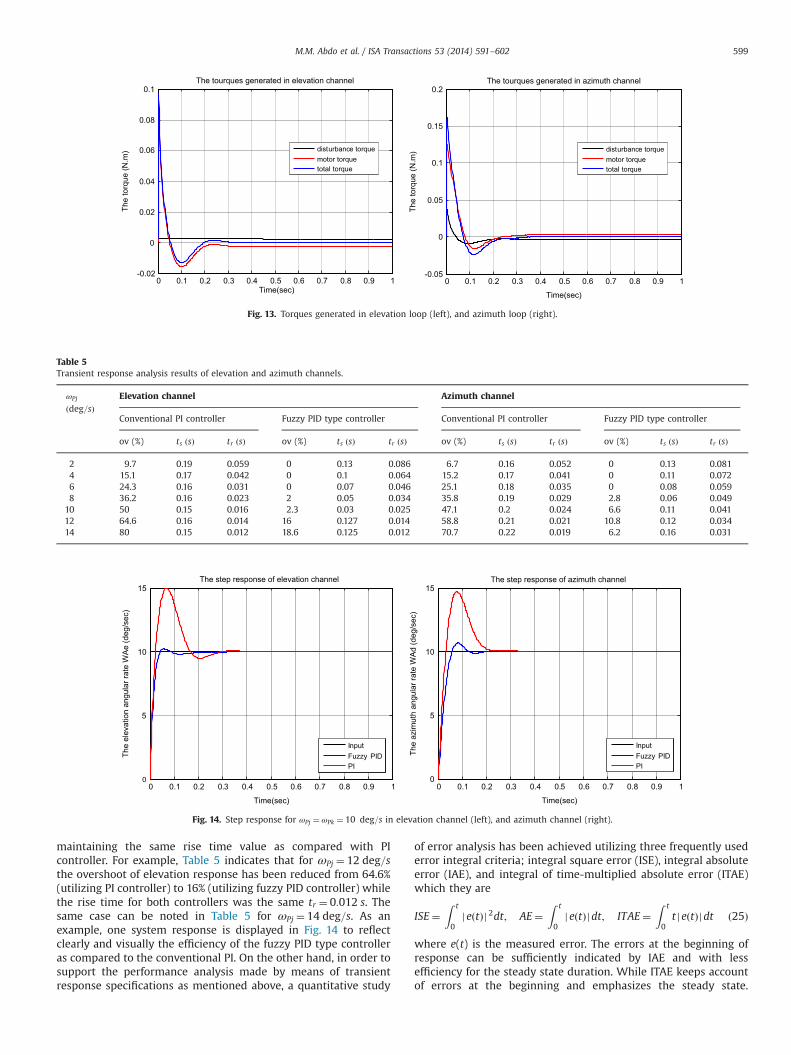
maintaining the same rise time value as compared with PIcontroller. For example, Table 5 indicates that for ωPj ¼ 12 deg=sthe overshoot of elevation response has been reduced from 64.6%(utilizing PI controller) to 16% (utilizing fuzzy PID controller) whilethe rise time for both controllers was the same tr ¼ 0:012 s. Thesame case can be noted in Table 5 for ωPj ¼ 14 deg=s. As anexample, one system response is displayed in Fig. 14 to reflectclearly and visually the efficiency of the fuzzy PID type controlleras compared to the conventional PI. On the other hand, in order tosupport the performance analysis made by means of transientresponse specifications as mentioned above, a quantitative study
of error analysis has been achieved utilizing three frequently usederror integral criteria; integral square error (ISE), integral absoluteerror (IAE), and integral of time-multiplied absolute error (ITAE)which they are
ISE¼Z t
0jeðtÞj 2dt; AE¼
Z t
0jeðtÞjdt; ITAE¼
Z t
0t jeðtÞjdt ð25Þ
where e(t) is the measured error. The errors at the beginning ofresponse can be sufficiently indicated by IAE and with lessefficiency for the steady state duration. While ITAE keeps accountof errors at the beginning and emphasizes the steady state.
0 0.1 0.2 0.3 0.4 0.5 0.6 0.7 0.8 0.9 1-0.02
0
0.02
0.04
0.06
0.08
0.1The tourques generated in elevation channel
Time(sec)
The
torq
ue (N
.m)
The
torq
ue (N
.m)disturbance torque
motor torquetotal torque
0 0.1 0.2 0.3 0.4 0.5 0.6 0.7 0.8 0.9 1-0.05
0
0.05
0.1
0.15
0.2The tourques generated in azimuth channel
Time(sec)
disturbance torquemotor torquetotal torque
Fig. 13. Torques generated in elevation loop (left), and azimuth loop (right).
Table 5Transient response analysis results of elevation and azimuth channels.
ωPj
ðdeg=sÞElevation channel Azimuth channel
Conventional PI controller Fuzzy PID type controller Conventional PI controller Fuzzy PID type controller
ov (%) ts ðsÞ tr ðsÞ ov (%) ts ðsÞ tr ðsÞ ov (%) ts ðsÞ tr ðsÞ ov (%) ts ðsÞ tr ðsÞ
2 9.7 0.19 0.059 0 0.13 0.086 6.7 0.16 0.052 0 0.13 0.0814 15.1 0.17 0.042 0 0.1 0.064 15.2 0.17 0.041 0 0.11 0.0726 24.3 0.16 0.031 0 0.07 0.046 25.1 0.18 0.035 0 0.08 0.0598 36.2 0.16 0.023 2 0.05 0.034 35.8 0.19 0.029 2.8 0.06 0.049
10 50 0.15 0.016 2.3 0.03 0.025 47.1 0.2 0.024 6.6 0.11 0.04112 64.6 0.16 0.014 16 0.127 0.014 58.8 0.21 0.021 10.8 0.12 0.03414 80 0.15 0.012 18.6 0.125 0.012 70.7 0.22 0.019 6.2 0.16 0.031
0 0.1 0.2 0.3 0.4 0.5 0.6 0.7 0.8 0.9 10
5
10
15The step response of elevation channel
Time(sec)
The
elev
atio
n an
gula
r rat
e W
Ae
(deg
/sec
)
InputFuzzy PIDPI
0 0.1 0.2 0.3 0.4 0.5 0.6 0.7 0.8 0.9 10
5
10
15The step response of azimuth channel
Time(sec)
The
azim
uth
angu
lar r
ate
WA
d (d
eg/s
ec)
InputFuzzy PIDPI
Fig. 14. Step response for ωPj ¼ωPk ¼ 10 deg=s in elevation channel (left), and azimuth channel (right).
M.M. Abdo et al. / ISA Transactions 53 (2014) 591–602 599

Therefore, integral criteria IAE and ITAE are considered becausethey respectively reflect the transient and steady state character-istics of the control system, The values of error integral criteriaobtained for elevation and azimuth channels are provided inTable 6 which indicates that the error in fuzzy PID controller isminimum as compared to PI controller which shows the super-iority of the proposed fuzzy controller.
7. Conclusion
A two axes gimbal system was proposed and its mathematicalmodel derived utilizing Lagrange equation considering the baseangular rates, the dynamic mass unbalance, and the cross couplingbetween elevation and azimuth channels. Then, the stabilizationloop was introduced and a self-tuning fuzzy PID type controllerwas designed. The overall control system has been created andsimulated using MATLAB/Simulink and SimMechanics tools toconfirm the validity and correction of the proposed system. Thetorque disturbance has been analysed, then the performance offuzzy PID type controller has been tested using transient responseanalysis and a quantitative study of error analysis. Based on theresults obtained, the following observations can be remarked.First, the proposed self tuning operation provides good adaptivityto the gimbal systemwhich offers high performance despite of thetorque disturbances so that it can be utilized more efficiently indynamical environment that usually imposes large variable baserates. Then, the proposed fuzzy controller can reduce the responsesettling time as compared with the conventional PI controller.Finally, the proposed fuzzy controller improves the closeness ofsystem response and support the system relative stability byreducing the response overshoot considerably without increasingthe response rise time dramatically i.e. without largely abaisse-ment or weakening the swiftness of system response like to whatusually take place when the conventional PID is used.
Appendix A. Azimuth channel torque relationships
Utilizing Eqs. (5) and (7) gives
∂ωBn
∂ _ψ¼ 0;
∂ωBe
∂ _ψ¼ 0;
∂ωBk
∂ _ψ¼ 1;
∂ωBn
∂ψ¼ωBe;
∂ωBe
∂ψ¼ �ωBn;
∂ωBk
∂ψ¼ 0
∂ωAr
∂ _ψ¼ � sin ε;
∂ωAe
∂ _ψ¼ 0;
∂ωAd
∂ _ψ¼ cos ε;
∂ωAr
∂ψ¼ωBe cos ε;
∂ωAe
∂ψ
¼ �ωBn;∂ωAd
∂ψ¼ωBe sin ε ðA:1Þ
Using (A.1), the two terms in Eq. (8) left side are converted into
∂T∂ _ψ
¼ �ðArωArþAreωAeþArdωAdÞ sin ε
þðArdωArþAdeωAeþAdωAdÞ cos εþBnkωBnþBkeωBeþBkωBk
ðA:2Þ
∂T∂ψ
¼ �ωBnðBneωBnþBeωBeþBkeωBkþAreωArþAeωAeþAdeωAdÞþωBeðBnωBnþBneωBeþBnkωBkÞþωBeðArωArþAreωAeþArdωAdÞ cos εþωBeðArdωArþAdeωAeþAdωAdÞ sin ε ðA:3Þ
Based on Eqs. (A.2), (A.3), and (5) the equation of azimuthgimbal motion can be derived as follows
Jeq _ωBk ¼ TAzþTd1þTd2þTd3 ðA:4Þwhere Td¼Td1þTd2þTd3 represents different azimuth gimbal inertiadisturbances, Jeq is the instantaneous moment of inertia about thek-axis. All components are defined as follows
Jeq ¼ BkþAr sin2εþAd cos 2ε �Ard sin ð2εÞ ðA:5Þ
Td1 ¼ ½BnþAr cos 2εþAd sin2εþArd sin ð2εÞ�ðBeþAeÞ�ωBnωBe
ðA:6Þ
Td2 ¼ �½BnkþðAd�ArÞ sin ε cos εþArd cos ð2εÞ�ð _ωBn�ωBeωBkÞ�ðBkeþAdecosε�Are sin εÞð _ωBeþωBnωBkÞ�ðBneþArecosεþAde sin εÞðω2
Bn�ω2BeÞ ðA:7Þ
Td3 ¼ €εðAre sin ε�Ade cos εÞþ _ε½ðAr�AdÞðωBn cos ð2εÞ�ωBk
sin ð2εÞÞ�þ _ε½2AreðωBn sin ð2εÞþωBk cos ð2εÞÞ�þ _ε½ðAde sin εþAre cos εÞðωAeþωBeÞ�AeωBn� ðA:8Þ
Inserting _ωBk obtained from (5c) in (A.4) converts it intoa differential equation for the elevation rate ωAd as
Jeq _ωAd ¼ TAz cos εþTd cos εþT 0d;
T 0d ¼ Jeq½ _ωBn sin εþωArðωAe�ωBeÞ�;
TD�AZ ¼ ðTd1þTd2þTd3Þ cos εþT 0d ðA:9Þ
where TD�AZ represents the disturbances affected on azimuthgimbal. The term Td1 well be denoted as TD�AZ1. Then, using _ωBn
from (4a), ωBk from (5c), _ωBefrom (4b), and (5b) the terms Td2 andTd3 are respectively denoted by
TD�AZ2 ¼ ½BnkþðAd�ArÞ sin ε cos εþArdð2 cos 2ε�1Þ��ð� _ωpj sin η� _ωpi cos ηþωBeωpk Þ�ðBneþArecosεþAde sin εÞðω2
Bn�ω2BeÞ
�ðBkeþAdecosε�Are sin εÞð _ωpj cos η� _ωpi sin ηþωBnωpk ÞðA:10Þ
TD�AZ3 ¼ _ωAeðAre sin ε�Ade cos εÞþðAde cos ε�Are sin εÞð _ωpj cos η� _ωpi sin ηÞþωAdωBnðAde�AretgεÞþω2
BnðAretgε�AdeÞ sin ε
Table 6Error analysis results of elevation and azimuth channels.
ωPj
ðdeg=sÞElevation channel Azimuth channel
Conventional PI controller Fuzzy PID type controller Conventional PI controller Fuzzy PID type controller
IAE ISE ITEA IAE ISE ITEA IAE ISE ITEA IAE ISE ITEA
2 0.01237 0.00147 0.00068 0.01253 0.001588 0.00057 0.00113 0.0014 0.00052 0.01318 0.0017 0.000614 0.01157 0.00127 0.00068 0.01046 0.00133 0.0004 0.0115 0.0013 0.00062 0.0119 0.0015 0.000516 0.0118 0.00119 0.00078 0.0092 0.001165 0.00033 0.0122 0.00129 0.00076 0.0109 0.00141 0.000448 0.0128 0.00123 0.00095 0.00846 0.001 0.0003 0.01334 0.00135 0.00094 0.0102 0.00131 0.0004
10 0.01425 0.00137 0.00116 0.00816 0.0001 0.00035 0.01472 0.00148 0.00115 0.0098 0.00122 0.0003812 0.01606 0.00162 0.0014 0.00736 0.00086 0.00028 0.0163 0.00168 0.00136 0.00972 0.00116 0.0004214 0.0181 0.00198 0.0016 0.00747 0.00084 0.00043 0.018 0.00195 0.0016 0.00912 0.0011 0.0004
M.M. Abdo et al. / ISA Transactions 53 (2014) 591–602600

þ2AreðωAe�ωBeÞωBntgεþ2ωAdωBeðAr�AdÞ sin ε
þ2AreωAdðωAe�ωBeÞ 2 cos ε� 1cos ε
� �þðωAe�ωBeÞ½ðAde sin εþAre cos εÞðωAeþωBeÞ�AeωBn�þωAeωBnðAr�AdÞ ðA:11ÞFrom (5a) we have ωAr ¼ �ωAdtgεþðωBn= cos εÞ, then using
ωBk from (5c), and _ωBn from (4a), the term T0d denoted by
TD�AZ4 ¼ Jeq
"�ωBeωBn
1þ sin 2εcos ε
!�ωAdωAetgε
þð _ωpi cos ηþ _ωpj sin ηÞ sin ε�ωBeωpk sin ε
þωAeωBn
cos εþ2ωAdωBetgε
#ðA:12Þ
Appendix B. Elevation channel torque relationships
From Eq. (5) we have
∂ωAr
∂ _ε¼ 0;
∂ωAe
∂ _ε¼ 1;
∂ωAd
∂ _ε¼ 0;
∂ωAr
∂ε¼ �ωAd;
∂ωAe
∂ε¼ 0;
∂ωAd
∂ε¼ωAr
ðB:1ÞUsing (B.1) in the kinetic energy for elevation gimbal
T ¼ ðω� ðH=2ÞÞA, the two terms in Eq. (12) left side are
∂T∂ _ε
¼ AeωAeþAreωArþAdeωAd;
∂T∂ε
¼ωArωAdðAd�ArÞ�AreωAdωAe�Ardðω2Ar�ω2
AdÞþAdeωArωAe
ðB:2ÞUsing (B.2) in (12) gives the elevation gimbal motion equation
as a differential equation for ωAe as follows
Ae _ωAe ¼ TELþðAd�ArÞωArωAdþArdðω2Ar�ω2
AdÞ�Adeð _ωAd�ωAeωArÞ�Areð _ωArþωAeωAdÞ; TD�EL ¼ ðAd�ArÞωArωAd
þArdðω2Ar�ω2
AdÞ�Adeð _ωAd�ωAeωArÞ�Areð _ωArþωAeωAdÞðB:3Þ
The elements of inertia matrix form the disturbance termTD�EL. Using _ωBn from (4a), _ωBkfrom (5c), and (5) converts thedisturbance term TD�EL into the following form
TD�EL ¼ TD�EL1þTD�EL2þTD�EL3þTD�EL4þTD�EL5
þTD�EL6þTD�EL7þTD�EL8þTD�EL9þTD�EL10 ðB:4Þ
TD�EL1 ¼ ðAde sin εþAre cos εÞ"�2ωBeωAd�2ωBeωBn sin ε
cos ε
þωBeωpk � _ωpi cos ηþ _ωpj sin η
#ðB:5Þ
TD�EL2 ¼ωBeωBnðAde cos ε�Are sin εÞ ðB:6Þ
TD�EL3 ¼ ðAd�ArÞ 2 cos ε� 1cos ε
� �½ωBnωAd�ω2
Bn sin ε� ðB:7Þ
TD�EL4 ¼ �4ArdωBnωAd sin ε ðB:8Þ
TD�EL5 ¼ 2ArdωBnωAdtg2ε ðB:9Þ
TD�EL6 ¼ Ardω2Ad
1cos 2ε
�2� �
ðB:10Þ
TD�EL7 ¼ ð _ωpk þ €ηÞ½Are sin ε�Ade cos ε� ðB:11Þ
TD�EL8 ¼ Ardω2Bn½�2 sin 2εþtg2ε� ðB:12Þ
TD�EL9 ¼ ðAd�ArÞ sin ε cos εþ2Ardω2Bn ðB:13Þ
TD�EL10 ¼ ðAd�ArÞtgε½2ωAdωBn sin ε�ω2Ad�ω2
Bn sin2ε� ðB:14Þ
References
[1] Masten MK. Inertially stabilized platform for optical imaging systems. IEEEControl Syst Mag 2008;28:47–64.
[2] Analytic study of inside–out/coincident gimbal dynamics; final report, TheBendix corporation, Guidance System divison; 1976.
[3] Stokum LA, Carroll GR. Precision stabilized platform for shipborne electro-optical systems, 493. SPIE; 1984; 414–25.
[4] Rue AK. precision stabilization systems. IEEE Trans Aerosp Electron Syst1974:34–42 (AES-10).
[5] Ekstrand B. Equations of motion for a two axes gimbal system. IEEE TransAerosp Electron Syst 2001;37:1083–91.
[6] Daniel R. Mass properties factors in achieving stable imagery from a gimbalmounted camera, Published in SPIE Airborne Intelligence, Surveillance.Reconnaissance (ISR) systems and applications V 2008;6946.
[7] Özgür, H, Aydan, E, İsmet, E. Proxy-based sliding mode stabilization of a two-axis gimbaled platform. In: Proceedings of the world congress on engineeringand computer science. San Francisco. USA (WCECS). I; 2011.
[8] Ravindra S. Modeling and simulation of the dynamics of a large size stabilizedgimbal platform assembly. Asian Int J Sci Technol Prod Manuf 2008;1:111–9.
[9] Khodadadi, H. Robust control and modeling a 2-DOF inertial stabilized plat-form. In: International conference on electrical, control and computer engi-neering. Pahang. Malaysia; 2011. p. 223–8.
[10] Smith BJ, Schrenck WJ, Gass WB, Shtessel YB. Sliding mode control in a twoaxis gimbal system. In: Proceedings of IEEE Aerospace Applications Confer-ence. 1999;5:457–70.
[11] Willian, JB, Steven, PT. Optimal motion stabilization control of an electro-optical sight system. In: Proceedings of SPIE Conference. 1111; 1989; p. 116-20.
[12] Bo L, Hullender D, DeRenzo M. Nonlinear induced disturbance rejection ininertial stabilization systems. IEEE Trans 1998;6:421–7.
[13] Lin CM, Hsu CF, Mon YJ. Self-organizing fuzzy learning CLOS guidance lawdesign. IEEE Trans 2003;39:1144–51.
[14] Tam KK, Lee TH, Mamum A, Lee MW, Khoh CJ. composite control of a gyromirror line of sight stabilization platform design and auto tuning. ISA Trans2001;40:155–71.
[15] Krishna Moorty JAR, Marathe R, Sule VR. H1 control law for line-ofsightstabilization for mobile land vehicles. Opt Eng 2002;41:2935–44.
[16] Li C, Jing W. Fuzzy PID controller for 2D differential geometric guidance andcontrol problem. IET Control Theory Appl 2007;1:564–71.
[17] Tong S, Li Y. Observer-based fuzzy adaptive control for strict-feedback non-linear systems. Fuzzy Sets Syst 2009;160:1749–64.
[18] Jamali N, Amlashi S. Design and implementation of fuzzy position controlsystem for tracking applications and performance comparison with conven-tional PID. IAES Int J Artif Intell (IJ-AI) 2012;1:31–44.
[19] Khuntia SR, Mohanty KB, Panda S, Ardil C. A comparative study of P–I, I–P,fuzzy and neuro-fuzzy controllers for speed control of DC motor drive, WorldAcademy of Science. Eng Technol 2010;44:525–9.
[20] Buckley J. Universal fuzzy controllers. Autom J (IFAC) 1992;28:1245–8.[21] Tong S, Li H. Fuzzy adaptive sliding-mode control for MIMO nonlinear
systems. IEEE Trans Fuzzy Syst 2003;11:354–60.[22] Krishna Moorty JAR, Marathe R, Hari B. Fuzzy controller for line of sight
stabilization system. Opt Eng 2004;43:1394–400.[23] Tan KC, Lee TH, Khor EF. Design and real-time implementation of a multi-
variable gyro-mirror line-of-sight stabilization platform. Fuzzy Sets Syst2002;128:81–93.
[24] AKARH M, TEMİZ İ. Motion controller design for the speed control of DC servomotor. Int J Appl Math Inf 2013;7:131–7.
[25] Tanjung H, Sasongko PH, Suharyanto S. Performance analysis of hybridPID-ANFIS for speed control of brushless DC motor base on identificationmodel system. Int J Computer Inf Technol 2013;2:694–700.
[26] Kennedy PJ, Kennedy RL. Direct versus indirect line of sight (LOS) stabilization.IEEE Trans Control Syst Technol 2003;11:3–15.
[27] Hilkert JM. Inertially stabilized platform technology. IEEE Control Syst Mag2008;28:26–46.
[28] Yu S, Zhao Y. A new measurement method for unbalanced moments in a two-axis gimbaled seeker. Chin J Aeronaut 2010;23:117–22.
[29] Tang KZ, Huang SN, Tan KK, Lee TH. Combined PID and adaptive nonlinearcontrol for servo mechanical systems. Mechatronics 2004;14:701–14.
[30] Malhotra R, Singh N, Singh Y. Design of embedded hybrid fuzzy-GA controlstrategy for speed control of DC motor: a servo control case study. IntJ Comput Appl 2010;6:37–46.
[31] Fujita, H, Sasaki, J. Torque control for DC servo motor using adaptive loadtorque compensation. In: Proceedings of the ninthWSEAS international con-ference on System science and simulation in engineering; 2010. p. 454–8.
[32] Musaab, S. Design and simulation of servomechanism for rate gyro stabilizedseeker. MSc thesis. MUT. Iran; 2010.
[33] Ho-Pyeong L, Inn-Eark Y. Robust control design for a two-axis gimbaledstabilization system, IEEEAC paper #1010. version 2007;3:1–7.
M.M. Abdo et al. / ISA Transactions 53 (2014) 591–602 601

[34] Hilkert, JM, Hullender, DA., Adaptive control system techniques applied toinertial stabilization systems. In: Proceedings of SPIE Conference. 1304; 1990.190–206.
[35] Wahid N, Hassan N, Rahmat MF, Mansor S. Application of intelligent controllerin feedback control loop for aircraft pitch control. Aust J Basic Appl Sci2011;5:1065–74.
[36] Karasakal O, Yesil E, Zelkaya MGU, Eksin I. Implementation of a new self-tuning fuzzy PID controller on PLC. Turk J Elec Engin 2005;13:277–86.
[37] Qiao W, Mizumoto M. PID type fuzzy controller and parameters adaptivemethod. Fuzzy Sets Syst 1996;78:23–35.
[38] Hu B, Mann GKI, Gosine RG. A new methodology for analytical and optimaldesign of fuzzy PID controllers. IEEE Trans Fuzzy Syst 1999;7:521–39.
[39] Rajani K, Mudi K, Pal R, Nikhil A. Robust self-tuning scheme for PI- and PD-type fuzzy controllers. IEEE Trans Fuzzy Syst 1999;7:2–16.
M.M. Abdo et al. / ISA Transactions 53 (2014) 591–602602


![Statistical Analyses and Properties of Viloft/Polyester ...iranarze.ir/wp-content/uploads/2017/11/8089-English-IranArze.pdf · Aghasian et al. [4] investigated the ... were performed](https://static.fdocuments.us/doc/165x107/5aa3ce247f8b9a7c1a8b4cf9/statistical-analyses-and-properties-of-viloftpolyester-et-al-4-investigated.jpg)


![User experiences with different regional health ...iranarze.ir/wp-content/uploads/2018/06/9184-English-IranArze.pdf · of electronic patient information [23]. 1.1.1. Health information](https://static.fdocuments.us/doc/165x107/5e169947fd6a9b28583add58/user-experiences-with-different-regional-health-of-electronic-patient-information.jpg)

