Broschyr Raleigh Hall - Ny fabrik för Norton keramiska slipskivor
STABILITY OF TRIAXIAL WEAVE FABRIC COMPOSITES EMPLOYING
FINITE ELEMENT MODEL WITH HOMOGENIZED CONSTITUTIVE
RELATION
NORHIDAYAH RASIN
A thesis submitted in fulfilment of the
requirements for the award of the degree of
Master of Engineering (Structure and Material)
Faculty of Civil Engineering
Universiti Teknologi Malaysia
JULY 2013
iii
To my beloved parents
Rasin B. Mat @Abdul Kadir
&
Salmi Bt.Jamino
my beloved husband
Rozali Zakaria
And my beloved son
Muhammad Naim Redza
iv
ACKNOWLEDGEMENT
First and foremost, praises to God, for giving me health and times to
complete this course of research. During this research, I have given all my efforts
and commitment to ensure the best for my thesis.
I would like to take this opportunity to express my appreciation to my
supervisor, Dr. Ahmad Kueh Beng Hong, for his guidance, critics, and compassion.
Also, I want to thank my co-supervisor, Dr. Airil Yasreen Mohd Yassin for his
attention in assisting me to carry out this research. Without their supports and
encouragement, it would be hard for me to complete this thesis.
I also want to thank my beloved parents, husband and family members for
their prayers and moral supports during my study. This appreciation also goes to all
staff of Steel Technology Centre (STC), lecturers of Civil Engineering Faculty, and
colleagues for their helps either directly or indirectly.
Through this research, I hope that these precious knowledge and experiences
can be used in my future career.
v
ABSTRACT
This study examines numerically the uniaxial stability of triaxial weave fabric
(TWF) composites employing finite element (FE) model with homogenized
constitutive relation. TWF, which presents high specific-strength and stiffness due to
its porous and lightweight properties, was previously modelled using solid elements
or plybased approach, and thus making computation considerably complex and time-
consuming. To circumvent these issues, the current FE formulation is of geometrical
nonlinearity employing Newton-Rhapson method where TWF unit cell is treated as a
standalone non-conforming composite plate element making use of the homogenized
ABD stiffness matrix, where Aij, Bij, and Dij indicate the extensional, coupling, and
bending stiffness, respectively in which degree of freedom has been greatly reduced.
By means of Matlab program, the currently formulated model has demonstrated good
agreement with existing numerical and experimental results from literature in terms
of elastic properties. For the buckling analysis, four types of boundary conditions are
explored: fully simply supported, fully-clamped, free-simply supported and free-
clamped. High dependencies of post-buckling patterns of compression load against
both maximum and minimum deflections on numerous aspect ratios from 0.25 to 5
are observed in TWF, from which a characteristic equation has been defined for
practical convenience before the occurrence of post-buckling. Such equation is
described on the basis of the critical buckling load, Nmax, and stiffness factor, S, the
best characterization of which is expressed in a logarithmic manner. The study has
recognized that the buckling characteristics correlate directly to TWF’s aspect ratios
and level of rigidity imposed through the boundary conditions.
vi
ABSTRAK
Kajian ini menyelidik secara berangka kestabilan satu arah komposit fabrik tenunan
tiga paksi menggunakan model unsur terhingga dengan hubungan juzuk seragam.
Komposit fabrik tenunan tiga paksi yang menunjukkan kekuatan tentu dan
kekukuhan yang tinggi daripada ciri-cirinya yang berliang dan ringan, telah
dimodelkan sebelum ini dengan menggunakan unsur pepejal atau berasaskan
pendekatan berlapis dan ini menjadikan pengiraannya kompleks dan memakan masa.
Oleh itu, unsur terhingga tak linear secara geometri telah dirumuskan menggunakan
Kaedah Newton-Rhapson di mana sel unit komposit fabrik tenunan tiga paksi telah
dianggap sebagai unsur plat komposit tak-selaras bersendiri menggunakan matriks
kekukuhan ABD seragam di mana Aij, Bij, dan Dij masing-masing merupakan
kekukuhan pemanjangan, gandingan dan lenturan di mana darjah kebebasan telah
dikurangkan. Dengan menggunakan program Matlab, rumusan model kajian ini telah
menunjukkan persetujuan yang baik dengan keputusan berangka dan eksperimen
yang sedia ada daripada literatur dalam bentuk sifat-sifat elastik . Untuk analisis
lengkokan, terdapat empat jenis keadaan sempadan yang diterokai: disokong mudah
penuh, diapit penuh, bebas-disokong mudah dan bebas-diapit. Kebergantungan tinggi
corak pasca lengkokan daya mampatan terhadap kedua-dua pesongan maksimum dan
minimum kepada nisbah aspek daripada 0.25 kepada 5 telah diperhati, yang mana
satu persamaan ciri telah dirumuskan sebelum berlakunya pasca lengkokan.
Persamaan tersebut dihuraikan berdasarkan beban lengkokan kritikal, Nmax, dan
faktor kekukuhan, S, di mana pencirian terbaik adalah dinyatakan dalam bentuk
logaritma. Kajian ini telah mengenalpasti bahawa ciri-ciri lengkokan berhubungkait
secara langsung terhadap nisbah aspek dan tahap kekukuhan komposit fabrik tenunan
tiga paksi yang dikenakan melalui keadaan sempadan.
vii
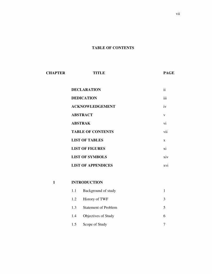
TABLE OF CONTENTS
CHAPTER TITLE PAGE
DECLARATION ii
DEDICATION iii
ACKNOWLEDGEMENT iv
ABSTRACT v
ABSTRAK vi
TABLE OF CONTENTS vii
LIST OF TABLES x
LIST OF FIGURES xi
LIST OF SYMBOLS xiv
LIST OF APPENDICES xvi
1 INTRODUCTION
1.1 Background of study 1
1.2 History of TWF 3
1.3 Statement of Problem 5
1.4 Objectives of Study 6
1.5 Scope of Study 7
viii
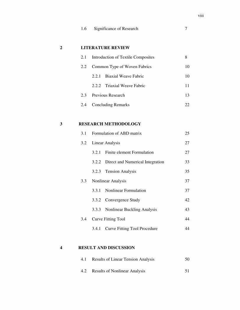
1.6 Significance of Research 7
2 LITERATURE REVIEW
2.1 Introduction of Textile Composites 8
2.2 Common Type of Woven Fabrics 10
2.2.1 Biaxial Weave Fabric 10
2.2.2 Triaxial Weave Fabric 11
2.3 Previous Research 13
2.4 Concluding Remarks 22
3 RESEARCH METHODOLOGY
3.1 Formulation of ABD matrix 25
3.2 Linear Analysis 27
3.2.1 Finite element Formulation 27
3.2.2 Direct and Numerical Integration 33
3.2.3 Tension Analysis 35
3.3 Nonlinear Analysis 37
3.3.1 Nonlinear Formulation 37
3.3.2 Convergence Study 42
3.3.3 Nonlinear Buckling Analysis 43
3.4 Curve Fitting Tool 44
3.4.1 Curve Fitting Tool Procedure 44
4 RESULT AND DISCUSSION
4.1 Results of Linear Tension Analysis 50
4.2 Results of Nonlinear Analysis 51
ix
4.2.1 Buckling Results 51
4.2.2 CFT Plotting 60
4.2.3 Post-Processing using Power Rule and 65
Logarithm Equation
5 CONCLUSION AND RECOMMENDATION
5.1 Conclusion of Findings 74
5.2 Recommendations 76
REFERENCES 77
APPENDIX A 79
APPENDIX B 80
x
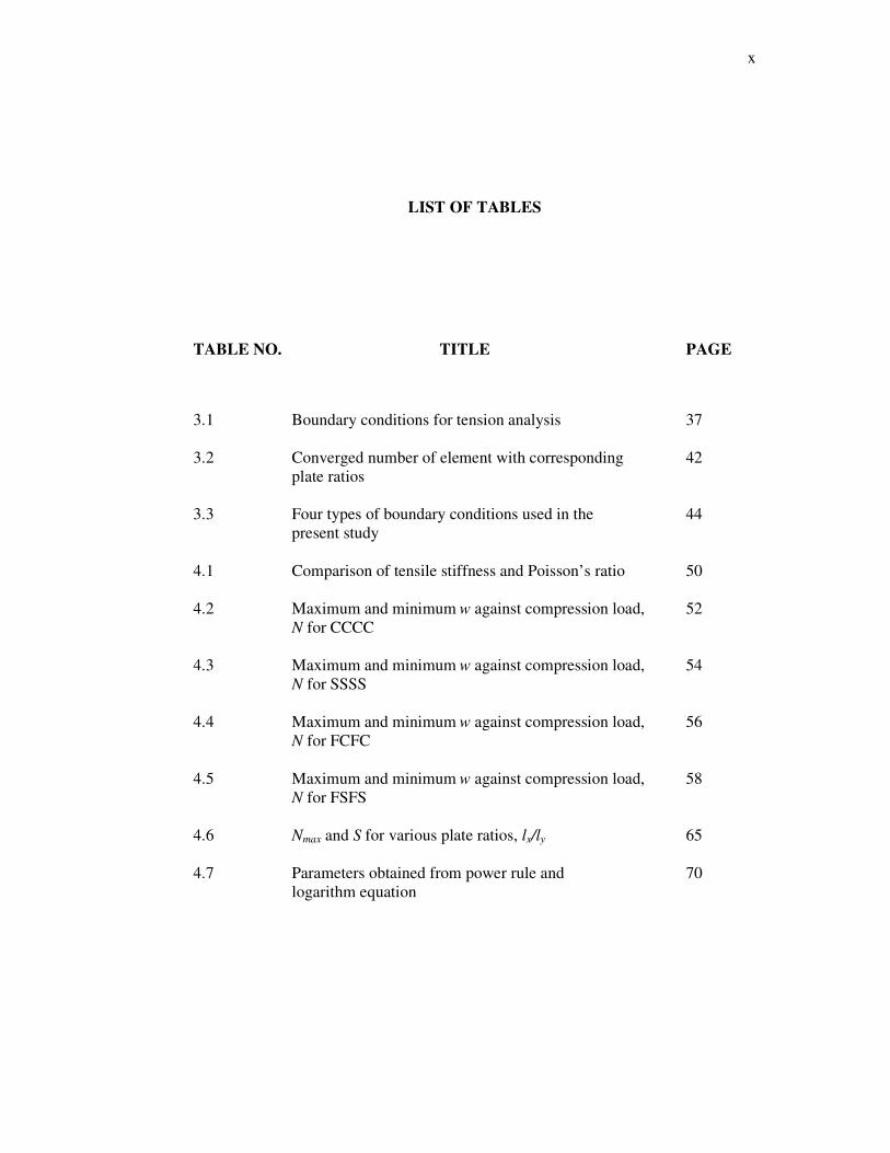
LIST OF TABLES
TABLE NO. TITLE PAGE
3.1 Boundary conditions for tension analysis 37
3.2 Converged number of element with corresponding 42
plate ratios
3.3 Four types of boundary conditions used in the 44
present study
4.1 Comparison of tensile stiffness and Poisson’s ratio 50
4.2 Maximum and minimum w against compression load, 52
N for CCCC
4.3 Maximum and minimum w against compression load, 54
N for SSSS
4.4 Maximum and minimum w against compression load, 56
N for FCFC
4.5 Maximum and minimum w against compression load, 58
N for FSFS
4.6 Nmax and S for various plate ratios, lx/ly 65
4.7 Parameters obtained from power rule and 70
logarithm equation
xi
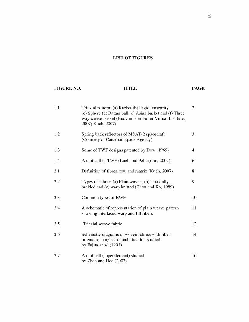
LIST OF FIGURES
FIGURE NO. TITLE PAGE
1.1 Triaxial pattern: (a) Racket (b) Rigid tensegrity 2
(c) Sphere (d) Rattan ball (e) Asian basket and (f) Three
way weave basket (Buckminster Fuller Virtual Institute,
2007; Kueh, 2007)
1.2 Spring back reflectors of MSAT-2 spacecraft 3
(Courtesy of Canadian Space Agency)
1.3 Some of TWF designs patented by Dow (1969) 4
1.4 A unit cell of TWF (Kueh and Pellegrino, 2007) 6
2.1 Definition of fibres, tow and matrix (Kueh, 2007) 8
2.2 Types of fabrics (a) Plain woven, (b) Triaxially 9
braided and (c) warp knitted (Chou and Ko, 1989)
2.3 Common types of BWF 10
2.4 A schematic of representation of plain weave pattern 11
showing interlaced warp and fill fibers
2.5 Triaxial weave fabric 12
2.6 Schematic diagrams of woven fabrics with fiber 14
orientation angles to load direction studied
by Fujita et al. (1993)
2.7 A unit cell (superelement) studied 16
by Zhao and Hoa (2003)
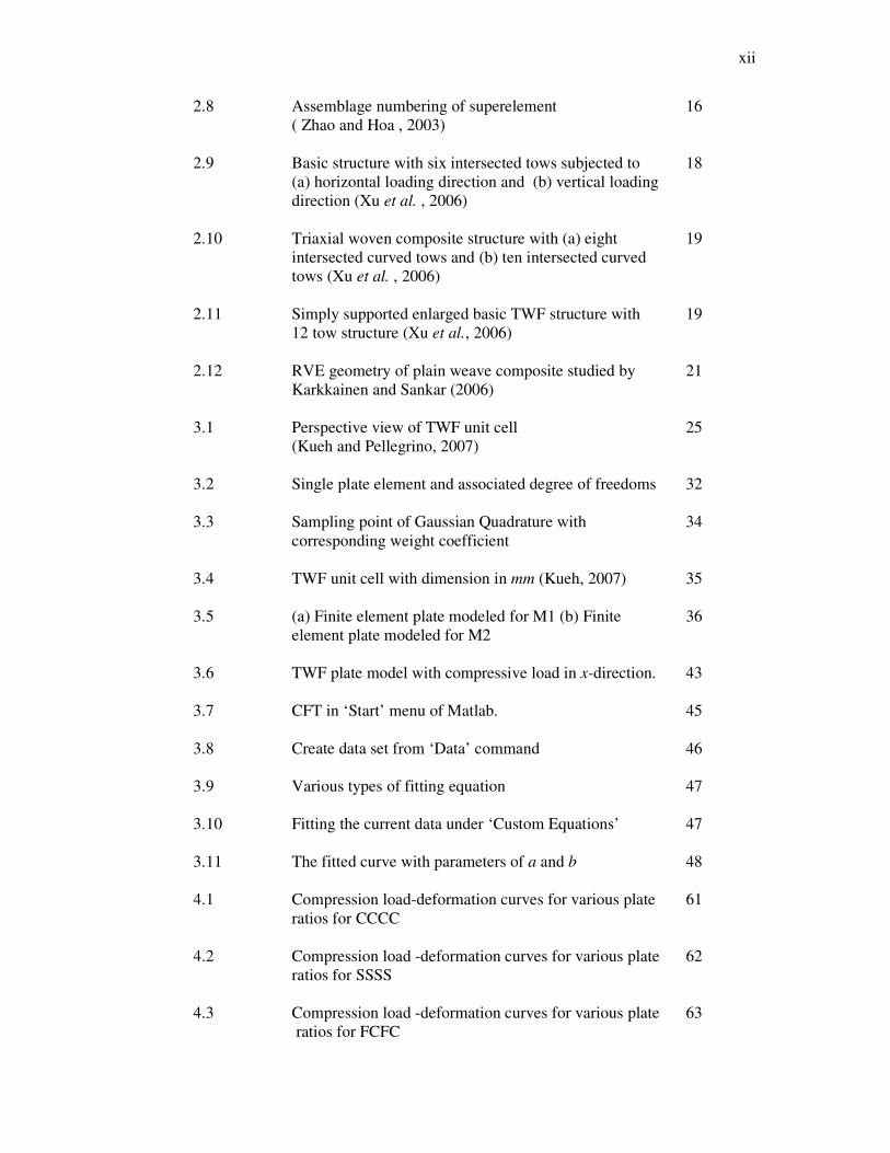
xii
2.8 Assemblage numbering of superelement 16
( Zhao and Hoa , 2003)
2.9 Basic structure with six intersected tows subjected to 18
(a) horizontal loading direction and (b) vertical loading
direction (Xu et al. , 2006)
2.10 Triaxial woven composite structure with (a) eight 19
intersected curved tows and (b) ten intersected curved
tows (Xu et al. , 2006)
2.11 Simply supported enlarged basic TWF structure with 19
12 tow structure (Xu et al., 2006)
2.12 RVE geometry of plain weave composite studied by 21
Karkkainen and Sankar (2006)
3.1 Perspective view of TWF unit cell 25
(Kueh and Pellegrino, 2007)
3.2 Single plate element and associated degree of freedoms 32
3.3 Sampling point of Gaussian Quadrature with 34
corresponding weight coefficient
3.4 TWF unit cell with dimension in mm (Kueh, 2007) 35
3.5 (a) Finite element plate modeled for M1 (b) Finite 36
element plate modeled for M2
3.6 TWF plate model with compressive load in x-direction. 43
3.7 CFT in ‘Start’ menu of Matlab. 45
3.8 Create data set from ‘Data’ command 46
3.9 Various types of fitting equation 47
3.10 Fitting the current data under ‘Custom Equations’ 47
3.11 The fitted curve with parameters of a and b 48
4.1 Compression load-deformation curves for various plate 61
ratios for CCCC
4.2 Compression load -deformation curves for various plate 62
ratios for SSSS
4.3 Compression load -deformation curves for various plate 63
ratios for FCFC
xiii
4.4 Compression load -deformation curves for various plate 64
ratios for FSFS
4.5 Nmax against plate ratios for (a) CCCC (b) SSSS 66
(c) FCFC and (d) FSFS using the power rule
4.6 S against plate ratios for (a) CCCC (b) SSSS (c) FCFC 67
and (d) FSFS using the power rule
4.7 Logarithm Nmax plotted against plate ratios for (a) CCCC 68
(b) SSSS (c) FCFC and (d) FSFS
4.8 Logarithm S plotted against plate ratios for (a) CCCC 69
(b) SSSS (c) FCFC and (d) FSFS
4.9 (a) IN,max and (b) mN,max obtained from power rule 71
and logarithm equation
4.10 (a) Is and (b) ms obtained from power rule 72
and logarithm equation
xiv
LIST OF SYMBOLS
a - Maximum value of y-axis
ɑº - Directions of tow
Aij - Extensional stiffness
b - Slope of curve over value of a
B - Strain-displacement matrix
Bij - Coupling stiffness
D - Constitutive matrix
Dij - Bending stiffness
F - Force vector
INmax and Is - Intercept of y-axis from Nmax and S data
K - Stiffness matrix
lx/ly - Plate ratio
Lx, Ly - Length of plate in x and y directions
mN,max and ms - Slope of the straight line from Nmax and S data
M - Mass matrix
Mxx, Myy - Moment resultants in x and y directions
Mxy - Twisting moment
n - Number of Gaussian Quadrature points
xv
N - Axial load
Nmax - Maximum buckling load
Nx - Compressive or axial load, N in x direction
Nxx, Nyy - Force resultants in x and y directions
Nxy - Shearing force resultant
S - Slope of curve
Sx - Tensile stiffness
κt - Tow thickness
u and v - In-plane displacements in the direction of x and y
f
iV - Volume segmentation of tows
w - Transverse displacement the z-direction
yx, and z - Directions of Cartesian coordinates system
k
ijC - Stiffness terms of TWF tow sets
γxy - Shear strain
εx and εy - Strains in x and y directions
κx and κy - Curvatures in x and y directions
κxy - Twisting curvature
vxy - Poisson’s ratio
ηξ , - Natural coordinates
e
jϕ - Interpolation functions for nonconforming rectangular
elements
φx, φy - Rotation in the directions of y and x
e
jψ
- Lagrange interpolation functions of elements used for
in-plane displacement
xvi
LIST OF APPENDICES
APPENDIX TITLE PAGE
A Material Properties of TWF 79
B Matlab Program Code 80
1
CHAPTER 1
INTRODUCTION
1.1 Background of study
Textile composite materials have been applied in large scale in numerous
engineering industries such as aerospace, marine, automobile, and sporting goods.
Due to the demand of lighter at the same time high performance materials in these
industries, the textile materials are seen to meet such requirements from material
selection process. Biaxial and triaxial fabric composites have been known as
common type of materials used in the textile industry and have attracted researchers
to study and investigate their unique mechanical characteristics since a few decades
ago during which aerospace industry has just initiated its dominance in engineering
field.
Based on previous study, triaxial weave fabric (TWF) composite has shown
more advantages and potential compared to biaxial weave fabric (BWF) composite in
terms of single ply comparison. Besides, TWF is often chosen as solution to
problems particularly related to lightweight and shear-resistance requirements, both
of which cannot be fulfilled by the conventional BWF.
2
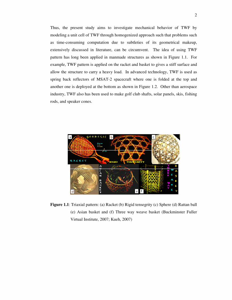
Thus, the present study aims to investigate mechanical behavior of TWF by
modeling a unit cell of TWF through homogenized approach such that problems such
as time-consuming computation due to subtleties of its geometrical makeup,
extensively discussed in literature, can be circumvent. The idea of using TWF
pattern has long been applied in manmade structures as shown in Figure 1.1. For
example, TWF pattern is applied on the racket and basket to gives a stiff surface and
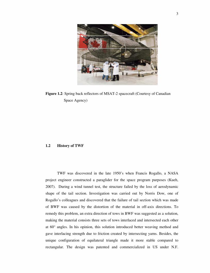
allow the structure to carry a heavy load. In advanced technology, TWF is used as
spring back reflectors of MSAT-2 spacecraft where one is folded at the top and
another one is deployed at the bottom as shown in Figure 1.2. Other than aerospace
industry, TWF also has been used to make golf club shafts, solar panels, skis, fishing
rods, and speaker cones.
Figure 1.1: Triaxial pattern: (a) Racket (b) Rigid tensegrity (c) Sphere (d) Rattan ball
(e) Asian basket and (f) Three way weave basket (Buckminster Fuller
Virtual Institute, 2007; Kueh, 2007)
3
Figure 1.2: Spring back reflectors of MSAT-2 spacecraft (Courtesy of Canadian
Space Agency)
1.2 History of TWF
TWF was discovered in the late 1950’s when Francis Rogallo, a NASA
project engineer constructed a paraglider for the space program purposes (Kueh,
2007). During a wind tunnel test, the structure failed by the loss of aerodynamic
shape of the tail section. Investigation was carried out by Norris Dow, one of
Rogallo’s colleagues and discovered that the failure of tail section which was made
of BWF was caused by the distortion of the material in off-axis directions. To
remedy this problem, an extra direction of tows in BWF was suggested as a solution,
making the material consists three sets of tows interlaced and intersected each other
at 60° angles. In his opinion, this solution introduced better weaving method and
gave interlacing strength due to friction created by intersecting yarns. Besides, the
unique configuration of equilateral triangle made it more stable compared to
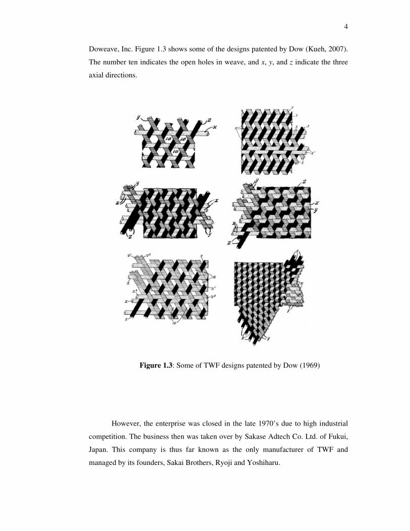
rectangular. The design was patented and commercialized in US under N.F.
4
Doweave, Inc. Figure 1.3 shows some of the designs patented by Dow (Kueh, 2007).
The number ten indicates the open holes in weave, and x, y, and z indicate the three
axial directions.
F
Figure 1.3: Some of TWF designs patented by Dow (1969)
However, the enterprise was closed in the late 1970’s due to high industrial
competition. The business then was taken over by Sakase Adtech Co. Ltd. of Fukui,
Japan. This company is thus far known as the only manufacturer of TWF and
managed by its founders, Sakai Brothers, Ryoji and Yoshiharu.
5
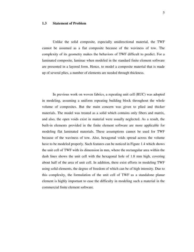
1.3 Statement of Problem
Unlike the solid composite, especially unidirectional material, the TWF
cannot be assumed as a flat composite because of the waviness of tow. The
complexity of its geometry makes the behaviors of TWF difficult to predict. For a
laminated composite, laminae when modeled in the standard finite element software
are presented in a layered form. Hence, to model a composite material that is made
up of several plies, a number of elements are needed through thickness.
In previous work on woven fabrics, a repeating unit cell (RUC) was adopted
in modeling, assuming a uniform repeating building block throughout the whole
volume of composites. But the main concern was given to plied and thicker
materials. The model was treated as a solid which contains only fibers and matrix,
and also, the open voids exist in material were usually neglected. As a result, the
built-in elements provided in the finite element software are more applicable for
modeling flat laminated materials. These assumptions cannot be used for TWF
because of the waviness of tow. Also, hexagonal voids spread across the volume
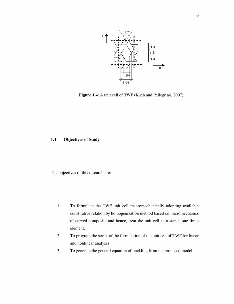
have to be modeled properly. Such features can be noticed in Figure 1.4 which shows
the unit cell of TWF with its dimension in mm, where the rectangular area within the
dash lines shows the unit cell with the hexagonal hole of 1.8 mm high, covering
about half of the area of unit cell. In addition, there exist efforts in modeling TWF
using solid elements, the degree of freedom of which can be of high intensity. Due to
this complexity, the formulation of the unit cell of TWF as a standalone planar
element is highly important to ease the difficulty in modeling such a material in the
commercial finite element software.
6
Figure 1.4: A unit cell of TWF (Kueh and Pellegrino, 2007)
1.4 Objectives of Study
The objectives of this research are:
1. To formulate the TWF unit cell macromechanically adopting available
constitutive relation by homogenization method based on micromechanics
of curved composite and hence, treat the unit cell as a standalone finite
element.
2. To program the script of the formulation of the unit cell of TWF for linear
and nonlinear analyses.
3. To generate the general equation of buckling from the proposed model.
7
1.5 Scope of the Study
This research is focused on the single-ply TWF composite. The fundamental
of finite element formulation is used to generate a standalone element for the unit
cell of TWF composite plate. 2D plate elements consisting five degrees of freedom
per node are employed. In this research, the assumption of Kirchhoff hypothesis for
thin plates is used in the formulation. Besides, a perfect bonding between tows is
assumed in the formulation. Only the elastic mechanical behaviors are of concern in
this study. Fracture of material is not considered. The Matlab software is used to
program the finite element formulation. The linear and nonlinear analyses of
buckling are conducted for numerous aspects ratios (0.25-5) and boundary
conditions. As mentioned in the objectives, one of the purposes of the analyses is to
produce some important parameters which can be used to represent the general
characteristics of buckling of TWF.
1.6 Significance of Research
By establishing the formulation of standalone composite element for unit cell
of TWF, it helps reduce the time-consuming and tedious process in the material
modeling, which is to date computationally expensive due to solid element meshing.
Considerably costly experimental method could be the main obstacle for composite
analysts to make characterization of material. Hence, it is very useful to apply
currently developed composite element adopting homogenized model and program
script, which give choices and freedoms to composite analysts, in any structure that
uses TWF as its reinforcing constituent. Furthermore, a list of characteristic terms
that expresses the buckling of TWF for numerous cases can be used instantaneously
to assess stability of this material without having to go through the lengthy nonlinear
computation process.
77
REFERENCES
Aoki, T. and Yoshida, K. (2006). Mechanical and Thermal Behaviors of Triaxially-
Woven Carbon/Epoxy Fabric Composite. 47th
AIAA/ASME/ASCE/AHS/ASC
Structures, Structural Dynamics, and Material Conference. Newport, Rhode
Island.
Buckminster Fuller Virtual Institute website. http://www.buckminster.info
Chou, T.W. and Ko, F.K. (1989). Textile Structural Composites, Volume 3
Composite Materials Series. New York, U.S.A.: Elsevier Science Publishers,
Amsterdam.
Cox, B. N. and Flanagan, G. (1997). Handbook of analytical methods for textile
composites. NASA Contractor Report 4750.
Dow, N. F. (1969). Triaxial fabric. United States Patent Office 3,446,251.
Fujita, A. , Hamada, H. and Maekawa, Z. (1993). Tensile Properties of Carbon Fiber
Trixial Woven Fabric Composites. Journal of Composite Materials, 27. 1428
– 1441.
Hoa, S.V., Sheng, S.Z. and Ouellette, P. (2003). Determination of Elastic Properties
of Triax Composite Materials. Composites Science and Technology. 63, 437-
443.
Karkkainen, R.L. and Sankar, B.V. (2006). A Direct Micromechanics Method for
Analysis of Failure Initiation of Plain Weave Textile Composites. Composite
Science and Technology, 66 (2006) 137 – 150.
Kueh, A.B.H (2007). Thermo-Mechanical Properties of Triaxial Weave Fabric
Composites. Ph.D. Thesis. University of Cambridge, United Kingdom.
Kueh, A.B.H. (2012). Fitting-Free Hyperelastic Strain Energy Formulation for
Triaxial Weave Fabric Composites. Mechanics of Materials. 47, 11-23.
Kueh, A.B.H. (2013).Compressive Response of Sandwich Columns Reinforced by
Triaxial Weave Fabric Composite Skinsheets. International Journal of
Mechanical Science, 66(2013) 45-54.
78
Kueh, A.B.H., and Pellegrino, S. (2007). ABD Matrix of Single-Ply Triaxial Weave
Fabric Composites. 48th AIAA/ASME/ASCE/AHS/ASC Structures, Structural
Dynamics, and Material Conference. Honolulu, Hawaii: AIAA-2007-2161.
Mahat, M.N.H (2013). Thermo-Mechanical Buckling of Triaxial Weave Fabric
Composites. Master Thesis. Universiti Teknologi Malaysia, Skudai,
Malaysia.
Peng, X.Q. and Cao, J. (2000). Numerical Determination of Mechanical Elastic
Constants of Textile Composites. 15th
Annual Technical Conference of the
American Society for Composite. College Station, TX.
Reddy, J.N. (2004). Mechanics of Laminated Composite Plates and Shells Theory
and Analysis. (2nd
ed.). Boca Raton : CRC Press LLC.
Schwartz, P. (1982). Bending Properties of Triaxially Woven Fabrics. Textile
Research Journal, 52, 604 – 606.
Skelton, J. (1971). Triaxially Woven Fabrics: Their structure and Properties. Textile
Research Journal, 41, 637 – 647.
Xu, D. , Ganesan, R. and Hoa, S.V. (2005). Buckling Analysis of Tri-axial Woven
Fabric Composite Structures. Part I: Non-linear Finite Element Formulation.
Compos Struct. 67, 37-55.
Xu, D. , Hoa, S.V. and Ganesan, R. (2006). Buckling Analysis of Tri-axial Woven
Fabric Composite Structures. Part II: Parametric Study – Uni-directional
Loading. Composite Structure. 72, 236-253.
Zhao, Q. and Hoa, S.V. (2003). Triaxial Woven Fabric (TWF) Composites with
Open Holes (Part I): Finite Element Models For Analysis. Journal of
Composite Materials. 37(9), 763-789.
Zhao, Q., Hoa, S.V. and Ouellette, P. (2003). Triaxial Woven Fabric (TWF)
Composites with Open Holes (Part II): Verification of the Finite Element
Models. Journal of Composite Materials. 37, 10.
Zienkiewicz, O.C. and Cheung, Y.K. (1964). The Finite Element Method for
Analysis of Elastic Isotropic and Orthotropic Slabs. Proceeding of the
Institute of Civil Engineers, London, UK, 28, 471-488.