Stability and Control in Computational Simulations for Conceptual and...
18
1 Stability and Control in Computational Simulations for Conceptual and Preliminary Design the past, today, and future? William H. Mason Department of Aerospace and Ocean Engineering Virginia Tech, Blacksburg, VA 24060, [email protected] Computational Methods for Stability and Control Symposium Hampton, VA September 23-25, 2003 Introductory comments
Transcript of Stability and Control in Computational Simulations for Conceptual and...
1
Stability and Control in Computational Simulationsfor Conceptual and Preliminary Design
the past, today, and future?
William H. MasonDepartment of Aerospace and Ocean Engineering
Virginia Tech, Blacksburg, VA 24060,[email protected]
Computational Methods for Stability and Control SymposiumHampton, VA
September 23-25, 2003
Introductory comments

2
The Problem In Conceptual Design
The Flight Controls Guys(if they’re even there, and worse, they may be EEs):“We need a complete 6 DOF, with an aero math modelfrom -90° to + 90° or else forget it”
The Conceptual Designers:“Just Use the Usual Tail Volume Coefficient”
Exaggerated? —Not That Much!
The Problem In Conceptual Design
This attitude is only slightly exaggerated, and both sides have good reasons for their attitudes. Inessence, it appears to originate because detailed control system development, and the assessment ofaircraft characteristics in terms of stability and control, requires an understanding of the aerodynamiccharacteristics at flight boundaries. Here, nonlinear aerodynamics typically produced a significantflow separation and component interactions dominate the analysis.

3
“Linear” aero finds the close connection betweenperformance and dCm/dCL: the X-29
• Performance was strongly related to design static stability
AIAA 82-0097
model usedin calculation
“Linear” aero finds the close connection betweenperformance and dCm/dCL: the X-29
The initial computational work in stability and control came about in the mid-60s, when numerousmethods to predict lift and pitching moment slopes were developed. For the early stages of designthe vortex lattice method emerged as the standard, and the Margason/Lamar code was used widely.Designers were mainly interested in predicting the neutral point of the basic configuration.
With the introduction of fly-by-wire and relaxed static stability concepts to increase vehicleperformance, stability and control needed to become an essential part of the early design process.This was done when longitudinal stability was connected to the trimmed drag of the airplane todetermine the center of gravity location (and the related static margin) required to achieve maximumperformance. John Lamar converted his code to compute minimum trimmed drag, allowing the staticmargin for minimum trimmed drag to be found early in the design process. An example thatillustrates this type of stability vs. performance layout process in the extreme is the X-29. Afterincluding transonic airfoil drag empirically in Lamar’s induced drag code, it was found that toachieve the performance potential of the Grumman forward swept wing concept, the configurationhad to be about 35% unstable.
This example is from W.H. Mason, “Wing-Canard Aerodynamics at Transonic Speeds -Fundamental Considerations on Minimum Drag Spanloads,” AIAA Paper 82-0097, January 1982
4
-0.0020
0.0000
0.0020
0.0040
0.0060
0.0080
0° 10° 20° 30° 40° 50°
Cnb - isolated forebody W.T. dataCnb - turbulent solutionCnb - inviscid solutionCnb - turb. sol'n (refined grid)Cnb - inviscid sol'n (refined grid)
Cnb
a
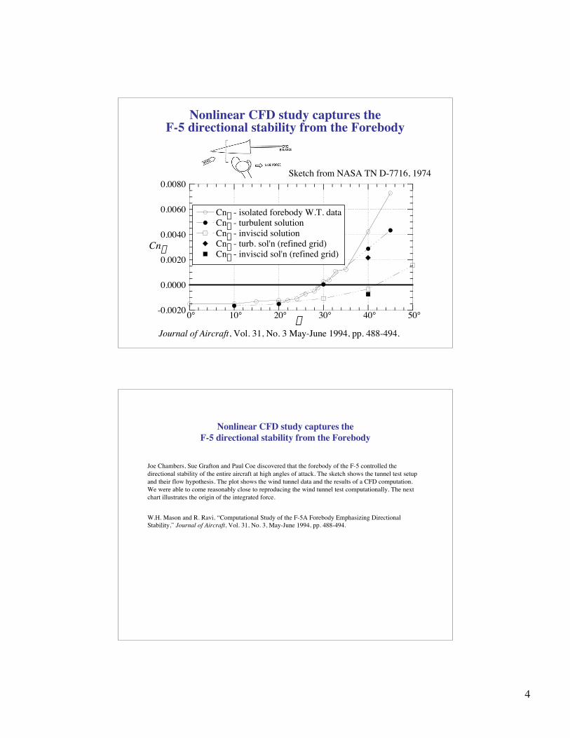
Nonlinear CFD study captures theF-5 directional stability from the Forebody
Journal of Aircraft, Vol. 31, No. 3 May-June 1994, pp. 488-494.
Sketch from NASA TN D-7716, 1974
Nonlinear CFD study captures theF-5 directional stability from the Forebody
Joe Chambers, Sue Grafton and Paul Coe discovered that the forebody of the F-5 controlled thedirectional stability of the entire aircraft at high angles of attack. The sketch shows the tunnel test setupand their flow hypothesis. The plot shows the wind tunnel data and the results of a CFD computation.We were able to come reasonably close to reproducing the wind tunnel test computationally. The nextchart illustrates the origin of the integrated force.
W.H. Mason and R. Ravi, “Computational Study of the F-5A Forebody Emphasizing DirectionalStability,” Journal of Aircraft, Vol. 31, No. 3, May-June 1994, pp. 488-494.

5
CFD also allows designers to understand thephysics so they can be designed
-0.20
-0.10
0.00
0.10
0.20
0 5 10 15 20 25 30 35
InviscidTurbulent
Axial coordinate, x
cy
a = 40°b = 5°
FS 14 FS 29.6 Top
Top
Bottom
Bottom
F-5A Forebody: CFL3D solution
DCp
• shaping can tailor characteristics• chine forebodies also investigated• next: add yaw damping
NASA CR 4465, 1992
CFD also allows designers to understand the physics so they can be designed
The CFD results can be used to understand the origin of the directional stability characteristics ofthe F-5A forebody. Comparing inviscid and viscous results, the role of viscosity can be explicitlyidentified. We also see that it the integrated force is the result of a rather complicated balance offorces. The associated computational flow visualization, available in the references below, alsoprovide insight into the structure of the flowfield.We also did similar calculations for chine-shaped forebodies. The references cited below providethe details.W.H. Mason and R. Ravi, “Computational Study of the F-5A Forebody Emphasizing DirectionalStability,” Journal of Aircraft, Vol. 31, No. 3, May-June 1994, pp. 488-494.Ravi and W.H. Mason, “A Computational Examination of Directional Stability for Smooth andChined Forebodies at High-a,” NASA CR 4465, August 1992.R. Ravi and W.H. Mason, “Chine-Shaped Forebody Effects on Directional Stability at High-a,”Journal of Aircraft, Vol. 31, No. 3, May-June 1994, pp. 480-487.

6
One example illustrating the incorporation of a keystability and control characteristic - pitchup -
in an MDO design processApproach• develop a means of estimating pitchup for cranked wing
planforms of interest for supersonic aircraft (HSCT)(Benoliel and Mason, AIAA Paper 94-1819)
• represent the nonlinear aero characteristics with a modelthat can be “called” many thousands of times during theMDO optimization process.(Crisafulli, et al, AIAA Paper 96-4136)
• an overview of this approach has been presented in aform suitable for aerodynamicists in AIAA 98-2513.
One example illustrating the incorporation of a key stability andcontrol characteristic - pitchup - in an MDO design process
The key to incorporating nonlinear aerodynamics in design is the use of models to represent the nonlinearaerodynamics without directly incorporating the expensive aerodynamic simulations. At Virginia Techwe’ve been doing this with response surface models. These are typically quadratic polynomials, andCrisafulli used four response surfaces to represent the pitchup characteristics of cranked wings. Ourapproach amounts to the development of a “data base” of solutions for a particular design project. Thisapproach is effective in exploiting the capabilities of parallel computing.Alex Benoliel and W.H. Mason, “Pitch-Up Characteristics for HSCT Class Planforms: Survey andEstimation,” AIAA Paper 94-1819, June 20-23, 1994.Crisafulli, P., Kaufman, M., Giunta, A.A., Mason, W.H, Grossman, B., Watson, L.T, and Haftka, R.T,“Response Surface Approximations for Pitching Moment, Including Pitch-Up, in the MDO Design of anHSCT,” AIAA Paper 96-4136, Sept. 1996.Mason, W.H., Knill, D.L., Giunta, A.A., Grossman, B., Haftka, R.T. and Watson, L.T., “Getting the FullBenefits of CFD in Conceptual Design,” AIAA 16th Applied Aerodynamics Conference, Albuquerque,NM, AIAA Paper 98-2513, June 1998.See also:Giunta, A.A., Golovidov, O., Knill, D.L., Grossman, B., Mason, W.H., Watson, L.T., and Haftka, R.T.,“Multidisciplinary Design Optimization of Advanced Aircraft Configurations,” Fifteenth InternationalConference on Numerical Methods in Fluid Dynamics, P. Kutler, J. Flores, J.-J. Chattot, Eds., in LectureNotes in Physics, Vol. 490, Springer-Verlag, Berlin, 1997, pp. 14-34.
7
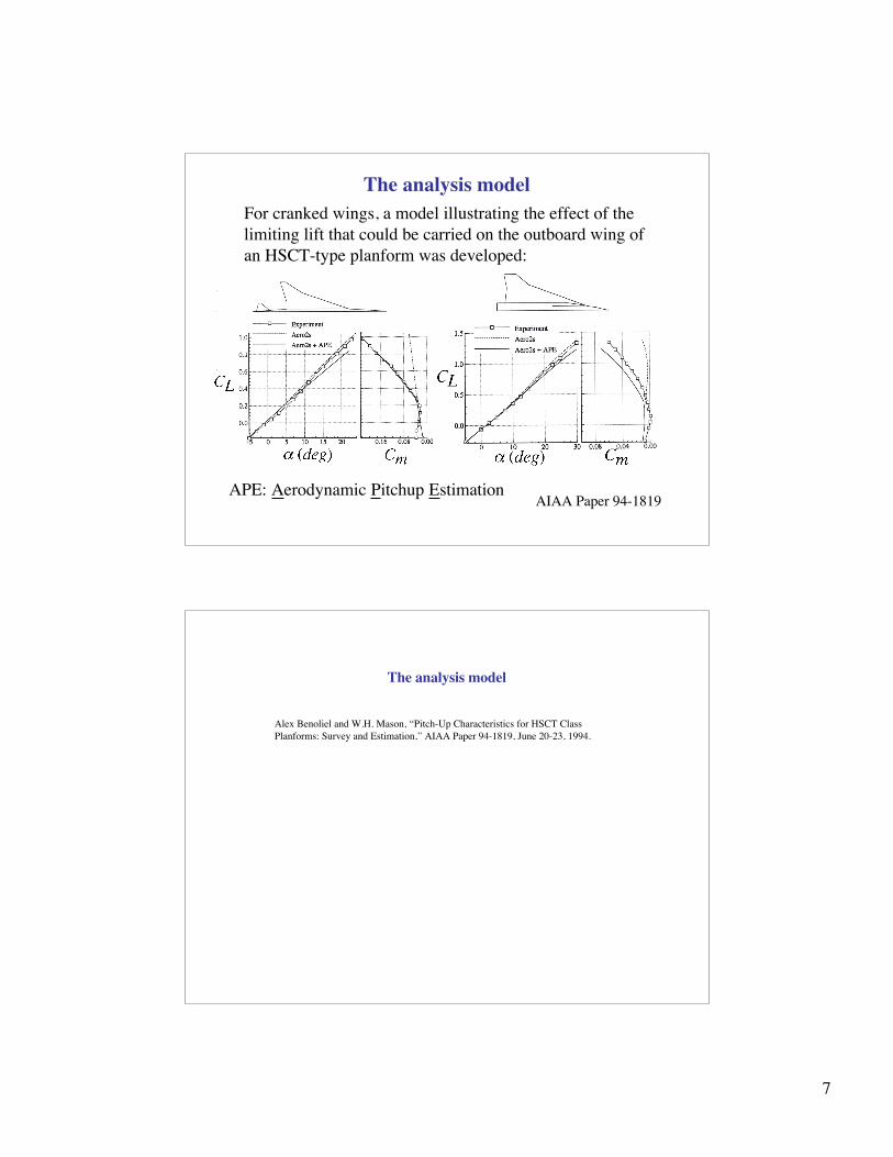
The analysis modelFor cranked wings, a model illustrating the effect of thelimiting lift that could be carried on the outboard wing ofan HSCT-type planform was developed:
AIAA Paper 94-1819APE: Aerodynamic Pitchup Estimation
The analysis model
Alex Benoliel and W.H. Mason, “Pitch-Up Characteristics for HSCT ClassPlanforms: Survey and Estimation,” AIAA Paper 94-1819, June 20-23, 1994.

8
Application to Design
AIAA 96-4126
• model the nonlinear aero with 2 straight lines and and aB• develop a “data base” (DOE) for this model in terms of the
planform variables, a Response Surface, RS
Application to Design
Crisafulli, P., Kaufman, M., Giunta, A.A., Mason, W.H, Grossman, B., Watson, L.T, and Haftka,R.T, “Response Surface Approximations for Pitching Moment, Including Pitch-Up, in the MDODesign of an HSCT,” AIAA Paper 96-4136, Sept. 1996.

9
MDO Results: An HSCT study
AIAA 96-4126
Baseline
No RS
Reduced Design Space
Pitchup RS Add Tail, Flaps RSLinear Cm RS
Design includes many trimand control constraints, as wellas tailscrape, etc.
MDO Results: An HSCT study
With the model of the pitchup characteristics established, the design can be done using MDO methods. Inthis case, many other control constraints are also included.
Crisafulli, P., Kaufman, M., Giunta, A.A., Mason, W.H, Grossman, B., Watson, L.T, and Haftka, R.T,“Response Surface Approximations for Pitching Moment, Including Pitch-Up, in the MDO Design of anHSCT,” AIAA Paper 96-4136, Sept. 1996.The final development of this methodology was described in the paper by Pete MacMillin, et al:P.E. MacMillin, J. Dudley, W.H. Mason, B. Grossman, and R.T. Haftka, “Trim, Control and LandingGear Effects in Variable-Complexity HSCT Design,” AIAA Paper 94-4381, Panama City, Fl., September1994.MacMillin, P. E., Golividov, O., Mason, W.H. Grossman, B., and Haftka, R.T., “Trim, Control, andPerformance Effects in Variable-Complexity High-Speed Civil Transport Design,” MAD Center Report96-07-01, July 1996. Virginia Tech, Blacksburg, VAMacMillin, P. E., Golividov, O., Mason, W.H. Grossman, B., and Haftka, R.T., “An MDO Investigationof the Impact on Practical Constraints on an HSCT Configuration,” AIAA Paper 97-0098, Reno, NV,January 1997.

10
Stability and Control in Tail Sizing: RSS/Active Controls
NASA CR-2408 (1974)
Stability and Control in Tail Sizing: RSS/Active Controls
The connection between stability and control and conceptual aircraft design has been of special interestsince active control started being considered. Many attempts to get active controls into the early stages ofdesign have been made. This chart comes from a report arising from a panel discussion in the early 1970s.
L. Gregor Hofmann and Warren F. Clement, “Vehicle Design Considerations for Active ControlApplication to Subsonic Transport Aircraft,” NASA CR-2408, August 1974.
Another example of how this could be done is available in:
Anderson, M. R. and Mason, W.H., “An MDO Approach to Control-Configured-Vehicle Design,” AIAAPaper 96-4058, Sept. 1996.

11
Conceptual/Preliminary Design Tools
• Linear Aerodynamics– Static stability characteristics– Control effectiveness– Dynamic stability characteristics
• Nonlinear Aerodynamics– Flow separation effects– Forebody/wing/canard vortex interactions
• Propulsion-related controls– and active flow control
• Accuracy expectations
Conceptual/Preliminary Design Tools

12
Example of “Scorecard” Validation: the XB-70
yaw pitch roll 50.0 0.0 -40.0
panels 1 thru 372
AIAA 95-0759
Stability derivatives
Derivative CLa Cma Cmq CYb Cnb Clb Clp Cnr
Subsonic
Supersonic
Control derivatives
Derivative CLdf Cmdf Cndf Cldf CLdc Cmdc CYdr Cndr Cldr
Subsonic
Supersonic
Very good Good Fair Poor Not usefulError<10% 10%<Error<25% 25%<Error<50% 50%<Error<100% 100%<Error
Note: Marty Waszak asked us for this
It’s hard togeneralizeresults in codevalidation andverification
Example of “Scorecard” Validation: the XB-70
Of course, “calibrated” estimates of control effectiveness should be made for the aerodynamic predictions,although there is considerable uncertainty. Our experience is that it is hard to generalize for allconfigurations. One good example came from McDonnell Douglas in St. Louis:
Thomas, R.W., “Analysis of Aircraft Stability and Control Design Methods,” AFWAL-TR-84-3038, Vol.II, App. B., “Evaluation of Aerodynamic Panel Methods,” by John Koegler, May, 1984.
At this point, the progress of stability and control computations in conceptual and preliminary slowed down.However, the linear methods continue to be key to design, and are continually being assessed. One exampleis the “Pie Charts” used to assess the capability of APAS, DATCOM and VLM methods for the XB-70.Valery Razgonyaev and W.H. Mason, “An Evaluation of Aerodynamic Prediction Methods Applied to theXB-70 for Use in High Speed Aircraft Stability and Control System Design,” AIAA Paper 95-0759, 33rdAIAA Aerospace Sciences Meeting and Exhibit, Reno, NV, Jan. 12, 1995.And the methods have formed the basis for a rudimentary system that can be used by students, and has beenadopted elsewhere:
J. Kay, W.H. Mason, F. Lutze and W. Durham, “Control Authority Issues in Aircraft Conceptual Design,”AIAA Paper 93-3968, August 1993.
Jacob Kay, W.H. Mason, W. Durham, F. Lutze and A. Benoliel, “Control Power Issues in ConceptualDesign: Critical Conditions, Estimation Methodology, Spreadsheet Assessment, Trim and Bibliography,”VPI-Aero-200, November 1993. http://www.aoe.vt.edu/~mason/Mason_f/MRsoft.html#Control PowerDynamic stability derivative predictions from Digital DATCOM were by Blake:W.B. Blake, “Prediction of Fighter Aircraft Dynamic Derivatives Using Digital Datcom,” AIAA Paper 85-4070, Colorado Springs, CO, October 1985.
13
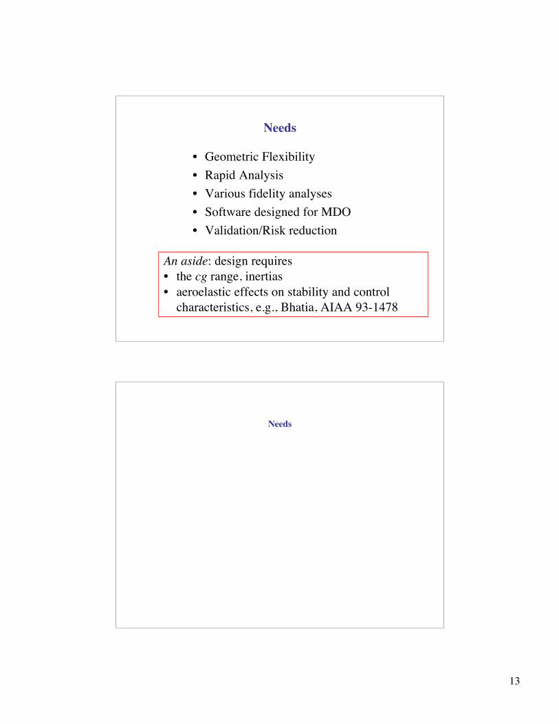
Needs
• Geometric Flexibility• Rapid Analysis• Various fidelity analyses• Software designed for MDO• Validation/Risk reduction
An aside: design requires• the cg range, inertias• aeroelastic effects on stability and control
characteristics, e.g., Bhatia, AIAA 93-1478
Needs
14
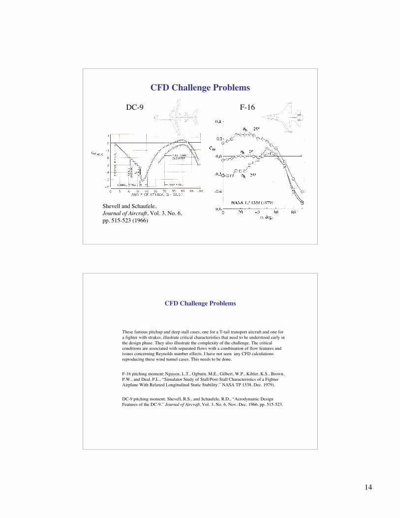
CFD Challenge Problems
DC-9 F-16
Shevell and Schaufele,Journal of Aircraft, Vol. 3, No. 6,pp. 515-523 (1966)
CFD Challenge Problems
These famous pitchup and deep stall cases, one for a T-tail transport aircraft and one fora fighter with strakes, illustrate critical characteristics that need to be understood early inthe design phase. They also illustrate the complexity of the challenge. The criticalconditions are associated with separated flows with a combination of flow features andissues concerning Reynolds number effects. I have not seen any CFD calculationsreproducing these wind tunnel cases. This needs to be done.
F-16 pitching moment: Nguyen, L.T., Ogburn, M.E., Gilbert, W.P., Kibler, K.S., Brown,P.W., and Deal, P.L., “Simulator Study of Stall/Post-Stall Characteristics of a FighterAirplane With Relaxed Longitudinal Static Stability,” NASA TP 1538, Dec. 1979).
DC-9 pitching moment: Shevell, R.S., and Schaufele, R.D., “Aerodynamic DesignFeatures of the DC-9,” Journal of Aircraft, Vol. 3, No. 6, Nov.-Dec. 1966, pp. 515-523.

15
Advanced concepts are “non-standard” leading tonew computational challenges
Today’s concepts come in a staggering array ofshapes, all presenting unusual aero modelingrequirements, now including UAVs and morphing
Advanced concepts are “non-standard” leading tonew computational challenges
The concepts here include a strut braced wing on an A-7, as proposed for REVCON a few years ago,and which required special transonic analysis of the wing-pylon-strut junction (Andy Ko, W.H. Masonand B. Grossman, “Transonic Aerodynamics of a Wing/Pylon/Strut Juncture,” 21st AIAA AppliedAerodynamics Conference, Orlando, FL, AIAA Paper 2003-4062, 23-26 June 2003)Another concept is Leroy Spearman’s “Inboard Wing” concept, which requires modeling the “tipvortex” when the wing has fuselage “end plates”We also see Jones’ oblique wing, Askin Isikveren’s X-wing, Joe Schetz’s quasi ring wing, and a JimMarchman design team’s roadable aircraft. Each of these concepts present different challenges, and wehaven’t even included any morphing concepts.

16
Competition: Europe has an organized effort• Vos, Rizzi, Darracq and Hirschel, “Navier-Stokes solvers in European
aircraft design,” Progress in Aerospace Sciences, Vol. 38, 2002– An eye-opening example of a well-conceived, effective
program• The best subsonic linear tool? Tornado, from KTH (Sweden)
A truly arbitrary geometry VLMcode, in MATLAB, and availablefree off the web. Simple enoughfor students to use in design
Competition: Europe has an organized effort
It’s worth mentioning that the Europeans have a coordinated effort that covers a broad rangeof CFD applications in aircraft design. The overview in Progress in Aerospace Sciencescited here provides some insight into this program.
17
Potential Approaches• Geometric generality
– asymmetric configurations– ground effects, multiple planes– “morphing” concepts, including nonconventional controls
• Aerodynamic fidelity– fast linear theory– approximate aerodynamic theories of the past still relevant
• insight for design from variable groupings, limitingbehavior - not available from CFD
– high fidelity codes/mesh generation with results fast enoughfor use on design problems (create RS models)
– static and dynamic stability derivatives from sensitivityanalysis (Cliff et al, AIAA Papers 98-0393, 99-4313, Park,et al, AIAA Paper 99-3136)
• Integrated aero-propulsion flowfield methodology for control(including active control)
Potential Approaches
The sensitivity approaches are particularly interesting, although Bob Hall has pointed outthat they won’t pick up hysteresis effects.
Limache, A C, and Cliff, E M., “Aerodynamic sensitivity theory for rotary stabilityderivatives,” Atmospheric Flight Mechanics Conference, Portland, OR, Aug. 9-11, 1999,AIAA Paper 99-4313, Journal of Aircraft, Vol. 37, no. 4, July-Aug. 2000, p. 676-683
Godfrey, Andrew G, and Cliff, Eugene M,, “Direct calculation of aerodynamic forcederivatives - A sensitivity-equation approach,” 36th Aerospace Sciences Meeting & Exhibit,Reno, NV, Jan. 12-15, 1998, AIAA Paper 98-0393
Michael A. Park, Lawrence L. Green, Raymond C. Montgomery, David L. Raney,“Determination of Stability and Control Derivatives Using Computational Fluid Dynamicsand Automatic Differentiation,” AIAA Paper 99-3136

18
To Conclude
• Aerodynamic stability and control characteristicswill be more and more important to future designs
• A coordinated effort to develop a suite oftools/understanding is critical for UScompetitiveness in advanced flight vehicle design
Note: Most of the papers described are available electronically at:http://www.aoe.vt.edu/people/whmason.html