Stability analysis of slopes with surcharge by LEM and FEM · Stability analysis of slopes with...
11
See discussions, stats, and author profiles for this publication at: https://www.researchgate.net/publication/308234079 Stability analysis of slopes with surcharge by LEM and FEM Article · October 2015 CITATION 1 READS 95 2 authors, including: Some of the authors of this publication are also working on these related projects: Quantitative Validation of DEM Based Results View project Effect of Clay Blanket and Chimney Filter against Seepage Failure View project Md. Mahmud Sazzad Rajshahi University of Engineering & Technology 49 PUBLICATIONS 110 CITATIONS SEE PROFILE All content following this page was uploaded by Md. Mahmud Sazzad on 18 September 2016. The user has requested enhancement of the downloaded file.
Transcript of Stability analysis of slopes with surcharge by LEM and FEM · Stability analysis of slopes with...

Seediscussions,stats,andauthorprofilesforthispublicationat:https://www.researchgate.net/publication/308234079
StabilityanalysisofslopeswithsurchargebyLEMandFEM
Article·October2015
CITATION
1
READS
95
2authors,including:
Someoftheauthorsofthispublicationarealsoworkingontheserelatedprojects:
QuantitativeValidationofDEMBasedResultsViewproject
EffectofClayBlanketandChimneyFilteragainstSeepageFailureViewproject
Md.MahmudSazzad
RajshahiUniversityofEngineering&Technology
49PUBLICATIONS110CITATIONS
SEEPROFILE
AllcontentfollowingthispagewasuploadedbyMd.MahmudSazzadon18September2016.
Theuserhasrequestedenhancementofthedownloadedfile.
International Journal of
Advanced Structures and Geotechnical Engineering
ISSN 2319-5347, Vol. 04, No. 04, October 2015
IJASGE 040404 Copyright © 2015 BASHA RESEARCH CENTRE. All rights reserved
Stability analysis of slopes with surcharge by LEM and FEM
MD. MONIRUZZAMAN MONI, MD. MAHMUD SAZZAD
Department of Civil Engineering, Rajshahi University of Engineering & Technology, Bangladesh
Email: [email protected], [email protected]
Abstract: This article demonstrates a finite element approach to analyze the response of slopes of homogeneous
and layered soil with shear strength reduction (SSR) technique. Slope failure may occur owing to a reduction of
shear strength with increasing plastic strains induced by loading. The present approach allows this failure
process and analysis is carried out using Mohr-Coulomb and Drucker-Prager yield criteria in which the shear
strength parameters are reduced. The effect of mesh on the factor of safety of slope is investigated. To assess the
reliability of the numerical result for slope stability analysis by the finite element SSR technique, its comparison
with the well known conventional methods namely Bishop Method (1955), Fellenius Method (1936) and
Spencer Method (1967) is shown for homogeneous and layered soil. Good agreement is found between the
conventional limit equilibrium methods (LEM) and finite element method (FEM). It is noted that FEM gives a
bit higher factor of safety than LEM. Besides, Drucker-Prager model gives higher factor of safety than that of
Mohr-Coulomb model regardless of the position of surcharge and slope angles for both the slopes of
homogeneous and layered soil. The factor of safety increases when the distance of surcharge increases from the
crest of the slope up to a certain level and beyond that, the effect of surcharge remains constant for slopes of
homogeneous and layered soil. The failure surfaces for both LEM and FEM have also been assessed.
Keywords: Slope stability, Surcharge, Finite element method, Shear strength reduction technique, Conventional
method, Factor of safety
1. Introduction:
Slope stability analysis is one of the most important
areas of interest in geotechnical engineering. There are
a lot of engineering structures which require
foundation systems to be placed near an existing slope
such as bridge abutment, tower footings, basement
construction of high rise building, etc. In construction
areas, slope may fail due to heavy rainfall, increase in
ground water table and change in stress condition.
Similarly, natural slopes that have been stable for
many years may suddenly fail due to change in
topography, external forces, loss of shear strength, and
weathering (Abramson et al. 2002). Therefore, it is a
common challenge to both researchers and
professionals to analyse the stability of slopes and
evaluate the certainty of the factor of safety. Lin and
Cao (2012) conducted the effect of shear strength
parameters, cohesion and internal friction angle, on the
stability of slope through theoretical derivation and
limit equilibrium method. In their study, changes in
the factor of safety of slope and slip surface were
investigated. Namdar (2010) presented the three-
wedge method for stability analysis of slope. The
influence of root trees on slope stability was studied
and different factors like geometry and gradient,
geologic materials, stratigraphy, hydrology and the
local effects on the shore process were analyzed as
well. Cala and Flisiak (2003) performed many
simulations for isotropic and homogeneous slope
using shear strength reduction (SSR) technique and
limit equilibrium methods (LEM). The influence of
elastic properties (Young’s modulus = E , Poison’s
ratio = ) on slope stability analysis were investigated
and it was noted that elastic properties negligibly
influenced the factor of safety of slope. In their study,
the effect of slope angle and slope height was carried
out as well and the results obtained by SSR technique
were compared with that of LEM.
Duncan (1996) proposed that the stability and
deformation of slope can be analyzed by finite element
method (FEM). Griffiths and Lane (1999) discussed
several examples of FEM based slope stability
analysis by comparing with other solution methods.
Zhang et al. (2010) evaluated the channel slope
stability of the East Route of the South-North Water
Diversion Project, China. Typical channel cross
section in Sanding Province was evaluated using SSR-
FEM. To describe the stress-strain relationship of the
soils, Duncan-Chang nonlinear constitutive model was
employed. The factor of safety calculated by strength
reduction method was compared with LEM. He and
Zhang (2012) described the stability analysis of a
homogeneous slope and showed that the equivalent
area circle Drucker-Prager yield criterion was suitable
for the stability analysis of slope.
For the stability analysis of slope, factor of safety can
be calculated by different methods. Over the past four
decades, numerical analyses have been conducted
mainly through conventional LEM. These methods are
statically indeterminate and require pre-assumptions to
determine the factor of safety. The application of LEM
is limited to the simple shape of slope and not
available for complex geometries. By contrast, the
numerical methods such as FEM have been widely
used over the last two decades. In FEM, any
assumption in advance of the failure shape and
location of the failure surface are not necessary
(Griffiths and Lane 1999).
MD. MONIRUZZAMAN MONI, MD. MAHMUD SAZZAD
International Journal of Advanced Structures and Geotechnical Engineering
ISSN 2319-5347, Vol. 04, No. 03, July 2015, pp 216-225
Even though many researches have been carried out
for the stability analysis of slope by LEM and FEM
for homogeneous soil but a few studies for layered soil
with surcharge on the stability analysis of slope have
been reported in the literature. Consequently, the
objectives of the present study are: (i) to investigate
the effect of mesh on the factor of safety of slope, (ii)
to compare the FEM based analysis result with that of
LEM, (iii) to evaluate the effect of soil layer on the
stability of slope, (iv) to assess the effect of the
position of surcharge and (v) to examine the mode of
slope failure obtained from FEM analysis and compare
the same with LEM.
2. Methods of Evaluating the Factor of Safety of
Slope:
2.1 Limit Equilibrium Methods:
Several limit equilibrium methods were available in
the literature to determine the factor of safety of slope.
Some of the well-known and widely used LEM
methods are Bishop method (1955), Fellenius method
(1936) and Spencer method (1967). The main
disadvantage of conventional LEM is that it requires
pre-assumptions to complete the solution. The solution
in LEM is simple; however, it can be inadequate in
case the slope fails by complex mechanism such as
internal deformation, brittle failure, etc. A summary of
several limit equilibrium methods and their
assumptions are presented in Table 1.
Table 1: Summery of limit equilibrium methods (SLOPE/W 2004; Abramson et al. 2002)
Methods Moment
Equilibrium
Force
Equilibrium
Shape of
Slip
surface
Interslice
Normal
(E)
Interslice
Shear
(T)
Assumptions
for T and E
Ordinary
or
Fellenius
Yes No Circular No No No interslice
forces
Bishop’s
Simplified Yes No Circular Yes No
The side
forces are
Horizontal
Janbu’s
Simplified No Yes
Any
shape Yes No
The side
forces are
Horizontal
Janbu’s
Generalised Yes (by slice) Yes
Any
shape Yes Yes
Applied line
of thrust and
moment
equilibrium
of slice
Lowe-Karafiath No Yes Any
shape Yes Yes
Average of
ground
surface and
slice base
inclination
Corps of
Engineers No Yes
Any
shape Yes Yes
Inclination of
ground
surface at top
of slice
Sarma Yes Yes Any
shape Yes Yes
Interslice
shear
Spencer Yes Yes Any
shape Yes Yes
Constant
inclination
Morgenstern-
Price Yes Yes
Any
shape Yes Yes
Defined by
2.2 Finite Element Method:
FEM is a powerful numerical tool for solving many
engineering problems and mathematical physics. Due
to rapid development of computer technology, FEM
has gained increasing popularity over the traditional
methods in geotechnical engineering. Generally, there
are two approaches to analyze the stability of slope
using FEM. One approach is to increase the gravity
load of soil element and the second approach is to
reduce the strength characteristics of the soil mass
usually called Shear Strength Reduction (SSR)
technique. The SSR technique is adopted in the
Stability analysis of slopes with surcharge by LEM and FEM
International Journal of Advanced Structures and Geotechnical Engineering
ISSN 2319-5347, Vol. 04, No. 03, July 2015, pp 216-225
present study by using a powerful FEM based
software GEO5 (2014). In SSR technique, it is
assumed that slope materials have elasto-plastic
behavior. The SSR is based on the progressive
reduction of soil strength parameters, and until
the failure of slope occurs. The factored shear-strength
parameters fc and
f are given as follows:
s
fF
cc , (1)
s
fF
tanarctan , (2)
where sF is a strength reduction factor. For details of
SSR technique, readers are referred to Griffiths and
Lane (1999).
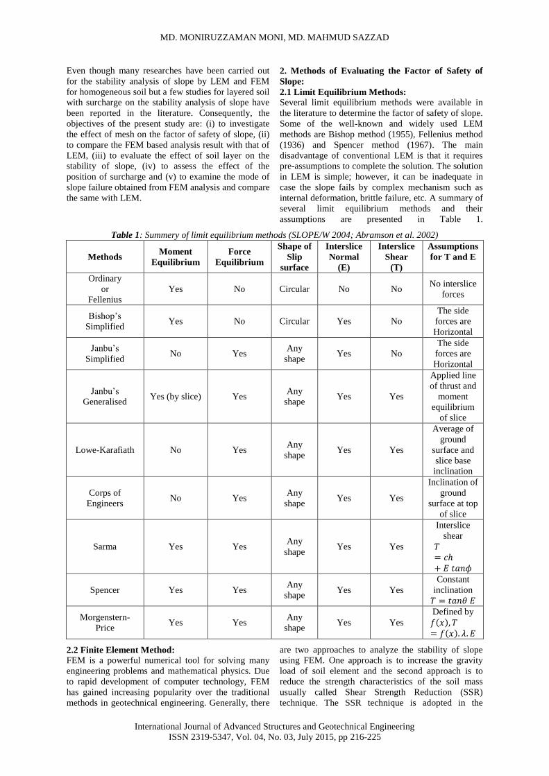
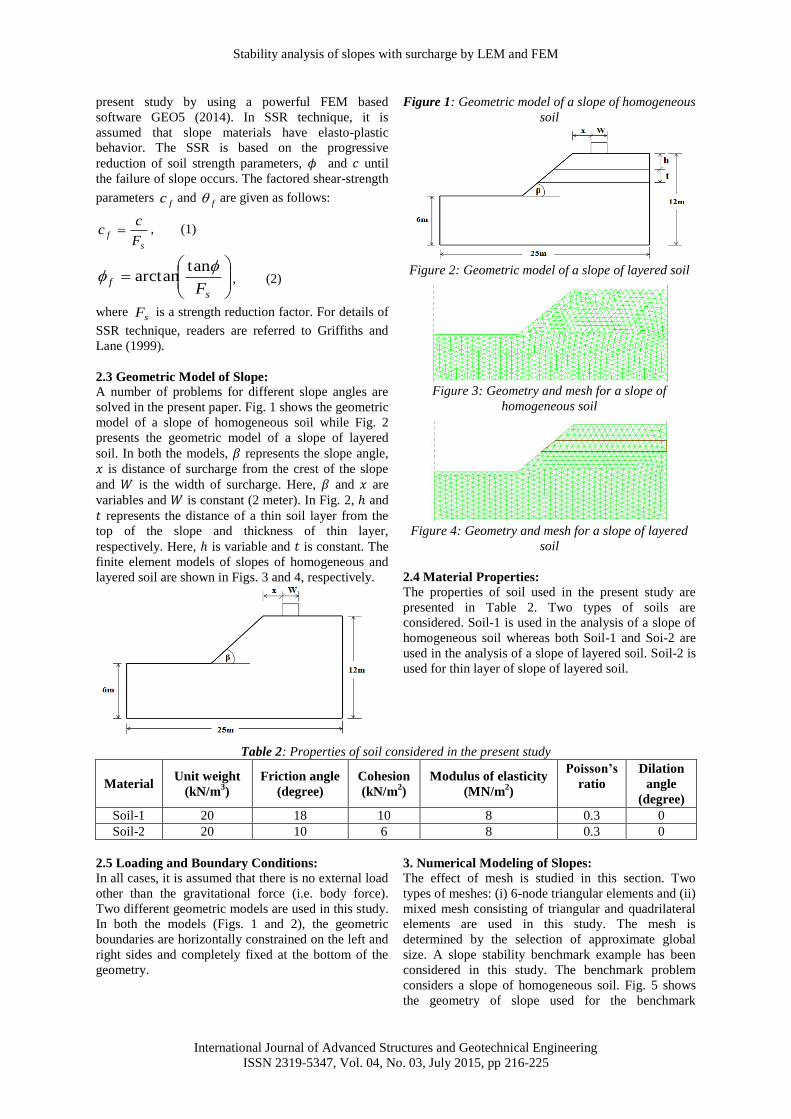
2.3 Geometric Model of Slope:
A number of problems for different slope angles are
solved in the present paper. Fig. 1 shows the geometric
model of a slope of homogeneous soil while Fig. 2
presents the geometric model of a slope of layered
soil. In both the models, represents the slope angle,
is distance of surcharge from the crest of the slope
and is the width of surcharge. Here, and are
variables and is constant (2 meter). In Fig. 2, and
represents the distance of a thin soil layer from the
top of the slope and thickness of thin layer,
respectively. Here, is variable and is constant. The
finite element models of slopes of homogeneous and
layered soil are shown in Figs. 3 and 4, respectively.
Figure 1: Geometric model of a slope of homogeneous
soil
Figure 2: Geometric model of a slope of layered soil
Figure 3: Geometry and mesh for a slope of
homogeneous soil
Figure 4: Geometry and mesh for a slope of layered
soil
2.4 Material Properties:
The properties of soil used in the present study are
presented in Table 2. Two types of soils are
considered. Soil-1 is used in the analysis of a slope of
homogeneous soil whereas both Soil-1 and Soi-2 are
used in the analysis of a slope of layered soil. Soil-2 is
used for thin layer of slope of layered soil.
Table 2: Properties of soil considered in the present study
Material Unit weight
(kN/m3)
Friction angle
(degree)
Cohesion
(kN/m2)
Modulus of elasticity
(MN/m2)
Poisson’s
ratio
Dilation
angle
(degree)
Soil-1 20 18 10 8 0.3 0
Soil-2 20 10 6 8 0.3 0
2.5 Loading and Boundary Conditions:
In all cases, it is assumed that there is no external load
other than the gravitational force (i.e. body force).
Two different geometric models are used in this study.
In both the models (Figs. 1 and 2), the geometric
boundaries are horizontally constrained on the left and
right sides and completely fixed at the bottom of the
geometry.
3. Numerical Modeling of Slopes:
The effect of mesh is studied in this section. Two
types of meshes: (i) 6-node triangular elements and (ii)
mixed mesh consisting of triangular and quadrilateral
elements are used in this study. The mesh is
determined by the selection of approximate global
size. A slope stability benchmark example has been
considered in this study. The benchmark problem
considers a slope of homogeneous soil. Fig. 5 shows
the geometry of slope used for the benchmark

MD. MONIRUZZAMAN MONI, MD. MAHMUD SAZZAD
International Journal of Advanced Structures and Geotechnical Engineering
ISSN 2319-5347, Vol. 04, No. 03, July 2015, pp 216-225
problem. The slope of the benchmark problem is
inclined at an angle of 29.74 degree to the horizontal.
In this example, ten different mesh configurations are
used to study the effects of mesh on the factor of
safety of slope. In this analysis, approximate global
size is varied from 0.5 to 1.5 for generating the
meshes. The value of 0.5 produces finer mesh than
that of 1.5. Ten analysis cases for the benchmark
model (Fig. 5) using FEM have been considered and
they are summarized in Table 3. The benchmark
models for the analysis cases 1 and 2 are depicted in
Figs. 6 and 7, respectively as examples. In Table 3,
‘TE6’ indicates 6-node triangular element and ‘Mixed’
indicates mixing of triangular and quadrilateral
elements.
Figure 5: Geometry of the benchmark model
Table 3: Different analysis cases for the benchmark
model by FEM
Analysis
case
Mesh
type
Element
number
Node
number
Analysis 1 TE6 411 694
Analysis 2 Mixed 295 572
Analysis 3 TE6 794 1391
Analysis 4 Mixed 541 1138
Analysis 5 TE6 1156 2061
Analysis 6 Mixed 776 1705
Analysis 7 TE6 1941 3544
Analysis 8 Mixed 1202 2791
Analysis 9 TE6 2655 4906
Analysis 10 Mixed 1610 3847
Figure 6: 6-node triangular elements with
approximate global size of 1.5
Figure 7: Mixed mesh with approximate global size of
0.5
4. Numerical Analysis by LEM and FEM:
In the present study, a number of numerical analyses
have been performed by the software GEO5 (2014).
Bishop method (1955), Fellenius method (1936) and
Spencer method (1967) are used for limit equilibrium
analysis. Mohr-Coulomb failure criterion and
Drucker-Prager yield criterion are used in finite
element analysis. For LEM, the geometric model is
incorporated in the GEO5 (2014) software and the
properties of soil are assigned for the specified
interface. In the analysis stage, a slip surface is added.
The slip surface may be circular or polygonal. In this
paper, circular slip surface is used. After assigning all
properties and slip circle, optimization method is
selected as analysis type. Finally, a surcharge is added
on the terrain of slope and analysis is carried out. For
the stability analysis of slopes using FEM, the first
step is to set the project parameters. Plane strain
project type is selected. Later, analysis type is set. The
geometric model is incorporated in the GEO5 (2014)
same as LEM. After incorporating the model, the
properties of soil are assigned for the specified
interface. For FEM analysis, meshes are generated and
a strip surcharge is added on the terrain of slope.
Finally, analysis is performed using the SSR technique
(Griffiths and Lane 1999).
5. Results and Discussions:
5.1 Effect of Mesh:
The effects of mesh on the factor of safety for ten
different mesh configurations are shown in Table 4. It
is noted that the computed factor of safety ranges from
1.37 to 1.54. The finer mesh gives more conservative
results than the coarser mesh. The factor of safety
using 6-node triangular elements is very close to that
of mixed mesh.
From the analysis of different cases, it can be
concluded that the factor of safety varies up to an
approximate active element number of 1200 for both
TE6 and mixed mesh and it remains constant for
active element number larger than 1200. Note that this
result is valid only for the geometry used in this study
and it may vary depending on the size of the geometry,
selection of global size and user’s experience.
Stability analysis of slopes with surcharge by LEM and FEM
International Journal of Advanced Structures and Geotechnical Engineering
ISSN 2319-5347, Vol. 04, No. 03, July 2015, pp 216-225
Table 4: Factor of safety for different analysis cases
Analysis case Method Mesh
type
Factor
of
safety
Analysis 1 FEM TE6 1.50
Analysis 2 FEM Mixed 1.54
Analysis 3 FEM TE6 1.46
Analysis 4 FEM Mixed 1.50
Analysis 5 FEM TE6 1.44
Analysis 6 FEM Mixed 1.46
Analysis 7 FEM TE6 1.44
Analysis 8 FEM Mixed 1.44
Analysis 9 FEM TE6 1.44
Analysis 10 FEM Mixed 1.44
Bishop LEM - 1.45
Fellenius LEM - 1.37
Spencer LEM - 1.44
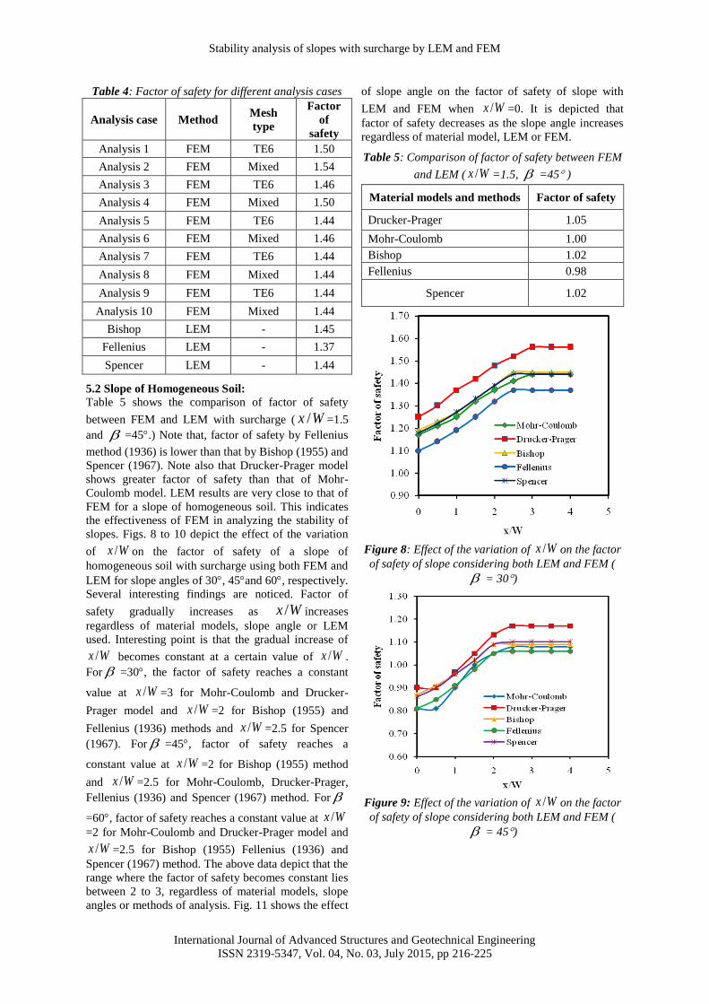
5.2 Slope of Homogeneous Soil:
Table 5 shows the comparison of factor of safety
between FEM and LEM with surcharge ( Wx / =1.5
and =45.) Note that, factor of safety by Fellenius
method (1936) is lower than that by Bishop (1955) and
Spencer (1967). Note also that Drucker-Prager model
shows greater factor of safety than that of Mohr-
Coulomb model. LEM results are very close to that of
FEM for a slope of homogeneous soil. This indicates
the effectiveness of FEM in analyzing the stability of
slopes. Figs. 8 to 10 depict the effect of the variation
of Wx / on the factor of safety of a slope of
homogeneous soil with surcharge using both FEM and
LEM for slope angles of 30, 45and 60, respectively.
Several interesting findings are noticed. Factor of
safety gradually increases as Wx / increases
regardless of material models, slope angle or LEM
used. Interesting point is that the gradual increase of
Wx / becomes constant at a certain value of Wx / .
For =30, the factor of safety reaches a constant
value at Wx / =3 for Mohr-Coulomb and Drucker-
Prager model and Wx / =2 for Bishop (1955) and
Fellenius (1936) methods and Wx / =2.5 for Spencer
(1967). For =45, factor of safety reaches a
constant value at Wx / =2 for Bishop (1955) method
and Wx / =2.5 for Mohr-Coulomb, Drucker-Prager,
Fellenius (1936) and Spencer (1967) method. For
=60, factor of safety reaches a constant value at Wx /=2 for Mohr-Coulomb and Drucker-Prager model and
Wx / =2.5 for Bishop (1955) Fellenius (1936) and
Spencer (1967) method. The above data depict that the
range where the factor of safety becomes constant lies
between 2 to 3, regardless of material models, slope
angles or methods of analysis. Fig. 11 shows the effect
of slope angle on the factor of safety of slope with
LEM and FEM when Wx / =0. It is depicted that
factor of safety decreases as the slope angle increases
regardless of material model, LEM or FEM.
Table 5: Comparison of factor of safety between FEM
and LEM ( Wx / =1.5, =45 )
Material models and methods Factor of safety
Drucker-Prager 1.05
Mohr-Coulomb 1.00
Bishop 1.02
Fellenius 0.98
Spencer 1.02
Figure 8: Effect of the variation of Wx / on the factor
of safety of slope considering both LEM and FEM (
= 30)
Figure 9: Effect of the variation of Wx / on the factor
of safety of slope considering both LEM and FEM (
= 45)

MD. MONIRUZZAMAN MONI, MD. MAHMUD SAZZAD
International Journal of Advanced Structures and Geotechnical Engineering
ISSN 2319-5347, Vol. 04, No. 03, July 2015, pp 216-225
Figure 10: Effect of the variation of Wx / on the
factor of safety of slope considering both LEM and
FEM ( = 60)
Figure 11: Effect of slope angle on the factor of safety
of slope for LEM and FEM
Fig. 12 shows the contours of the equivalent plastic
strain (a measure of the amount of permanent strain in
an engineering body) for a slope of homogeneous soil
( =30) by FEM while Fig. 13 presents the failure of
a slope of homogeneous soil ( =30) with surcharge
using LEM. Similarly, Fig. 14 shows the contours of
the equivalent plastic strain for a slope of
homogeneous soil ( =45) by FEM while Fig. 15
presents the failure of a slope of homogeneous soil (
=45) with surcharge using LEM. It is obvious from
Figs. 12 to 15 that slip surfaces obtained from FEM
are localized deeper than LEM irrespective of slope
angles when homogeneous soil is considered.
Figure 12: Contours of the equivalent plastic strain
for a slope of homogeneous soil ( =30) with
surcharge by FEM
Figure 13: Failure of a slope of homogeneous soil (
=30) with surcharge using LEM
Figure 14: Contours of the equivalent plastic strain
for a slope of homogeneous soil ( =45) with
surcharge by FEM
Figure 15: Failure of a slope of homogeneous soil (
= 45) with surcharge using LEM
Stability analysis of slopes with surcharge by LEM and FEM
International Journal of Advanced Structures and Geotechnical Engineering
ISSN 2319-5347, Vol. 04, No. 03, July 2015, pp 216-225
5.3 Slope of Layered Soil:
The effect of the variation of the position of a thin
weak layer (thickness= t ) from top of the slope on the
factor of safety is discussed in this section. The
thickness of the thin weak layer is set to 2 meter and
the position of this layer is varied. First, the weak
layer is considered at the top of the slope (i.e. 0/ th
). Fig. 16 shows the effect of the position of surcharge
on the factor of safety of slope of layered soil by LEM
and FEM for 0/ th and =30. Similar results
are depicted in Figs. 17, 18 and 19 for th / 1, 2 and
3, respectively and =30. Drucker-Prager model
depicts the highest factor of safety compared to Mohr-
Coulomb model regardless of the position of the thin
weak soil layer. When 1,0/ th , FEM results
considering Mohr-Coulomb model and LEM give
almost same results. However, difference is apparent
as th / keeps increasing (Figs. 18 and 19). Similar
results are noticed for slope angles of 45 and 60.
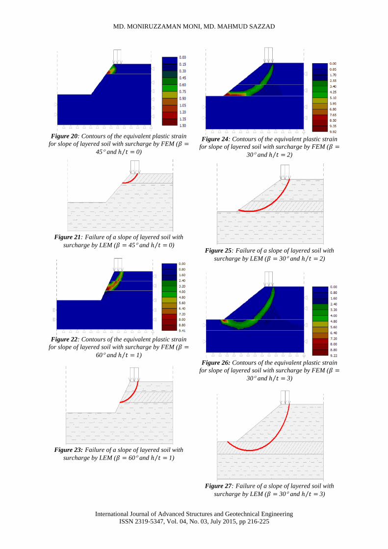
Fig. 20 shows the contours of the equivalent plastic
strain for a slope of layered soil by FEM ( = 45
and th / 0) while Fig. 21 depicts the failure of a
slope of layered soil by LEM ( = 45 and th / 0).
Note that when weak soil layer is located at the top of
the slope, the failure of slope occurs only in the weak
portion of the soil. As the position of the weak soil
layer changes from the top of the slope (i.e. h
increases), the failure line (i.e. slip surfaces) extends to
the end of the weak layer (Figs. 22-27). When weak
soil layer is located at the foundation layer of the slope
(Figs. 26-27), slip surfaces also extend to the
foundation layer.
Figure 16: Effect of the variation of Wx / on the
factor of safety of slope ( th / 0 and = 30)
Figure 17: Effect of the variation of Wx / on the
factor of safety of slope ( th / 1, =30)
Figure 18: Effect of the variation of Wx / on the
factor of safety of slope ( th / 2 and =30)
Figure 19: Effect of the variation of Wx / on the
factor of safety of slope ( th / 3 and =30)
MD. MONIRUZZAMAN MONI, MD. MAHMUD SAZZAD
International Journal of Advanced Structures and Geotechnical Engineering
ISSN 2319-5347, Vol. 04, No. 03, July 2015, pp 216-225
Figure 20: Contours of the equivalent plastic strain
for slope of layered soil with surcharge by FEM (
45 and 0)
Figure 21: Failure of a slope of layered soil with
surcharge by LEM ( 45 and 0)
Figure 22: Contours of the equivalent plastic strain
for slope of layered soil with surcharge by FEM (
60 and 1)
Figure 23: Failure of a slope of layered soil with
surcharge by LEM ( 60 and 1)
Figure 24: Contours of the equivalent plastic strain
for slope of layered soil with surcharge by FEM (
30 and 2)
Figure 25: Failure of a slope of layered soil with
surcharge by LEM ( 30 and 2)
Figure 26: Contours of the equivalent plastic strain
for slope of layered soil with surcharge by FEM (
30 and 3)
Figure 27: Failure of a slope of layered soil with
surcharge by LEM ( 30 and 3)
Stability analysis of slopes with surcharge by LEM and FEM
International Journal of Advanced Structures and Geotechnical Engineering
ISSN 2319-5347, Vol. 04, No. 03, July 2015, pp 216-225
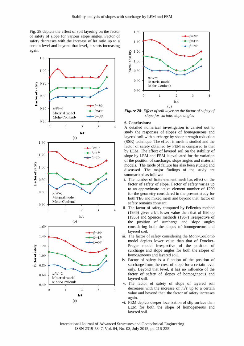
Fig. 28 depicts the effect of soil layering on the factor
of safety of slope for various slope angles. Factor of
safety decreases with the increase of h/t ratio up to a
certain level and beyond that level, it starts increasing
again.
(a)
(b)
(c)
(d)
Figure 28: Effect of soil layer on the factor of safety of
slope for various slope angles
6. Conclusions:
A detailed numerical investigation is carried out to
study the responses of slopes of homogeneous and
layered soil with surcharge by shear strength reduction
(SSR) technique. The effect is mesh is studied and the
factor of safety obtained by FEM is compared to that
by LEM. The effect of layered soil on the stability of
slope by LEM and FEM is evaluated for the variation
of the position of surcharge, slope angles and material
models. The mode of failure has also been studied and
discussed. The major findings of the study are
summarized as follows:
i. The number of finite element mesh has effect on the
factor of safety of slope. Factor of safety varies up
to an approximate active element number of 1200
for the geometry considered in the present study for
both TE6 and mixed mesh and beyond that, factor of
safety remains constant.
ii. The factor of safety computed by Fellenius method
(1936) gives a bit lower value than that of Bishop
(1955) and Spencer methods (1967) irrespective of
the position of surcharge and slope angles
considering both the slopes of homogeneous and
layered soil.
iii. The factor of safety considering the Mohr-Coulomb
model depicts lower value than that of Drucker-
Prager model irrespective of the position of
surcharge and slope angles for both the slopes of
homogeneous and layered soil.
iv. Factor of safety is a function of the position of
surcharge from the crest of slope for a certain level
only. Beyond that level, it has no influence of the
factor of safety of slopes of homogeneous and
layered soil.
v. The factor of safety of slope of layered soil
decreases with the increase of up to a certain
value and beyond that, the factor of safety increases
again.
vi. FEM depicts deeper localization of slip surface than
LEM for both the slope of homogeneous and
layered soil.
MD. MONIRUZZAMAN MONI, MD. MAHMUD SAZZAD
International Journal of Advanced Structures and Geotechnical Engineering
ISSN 2319-5347, Vol. 04, No. 03, July 2015, pp 216-225
References:
[1] Abramson, L.W., Lee T.S., Sharma, S. and
Boyce, G.M. (2002) “Slope Stability and
Stabilisation Methods.” John Wiley & Sons, Inc,
New York, USA.
[2] Bishop, A.W. (1955) “The use of the slip circle in
the stability analysis of slope.” Geotechnique,
Vol. 5(1), 7-17.
[3] Cala, M. and Flisiak, J. (2003) “Slope stability
analysis with numerical and limit equilibrium
methods.” In proceedings of the 15th
International
Conference on Computer Methods in Mechanics,
Gliwice, Poland, 1-4.
[4] Duncan, J.M. (1996) “State of the art: Limit
equilibrium and finite element analysis of slopes.”
Journal of Geotechnical Engineering, Vol. 122
(7), 577-596.
[5] Fellenius, W. (1936) “Calculation of the stability
of earth dams.” In proceeding of the 2nd congress
on large dams, Washington, D.C., Vol. 4, U.S.
Government Printing Office.
[6] GEO5 v18 (2014) “Users manual.” Fine software
company, Czech Republic.
[7] Griffiths, D.V. and Lane, P.A. (1999) “Slope
stability analysis by finite elements.”
Geotechnique, Vol.49(3), 387-403.
[8] He, B. and Zhang, H. (2012) “Stability analysis of
slope based on finite element method.” I.J
Engineering and Manufacturing, Vol.3, 70-74.
[9] Lin, H. and Cao, P. (2012) “Limit equilibrium
analysis for the relationships among slope c,
and slip surface.” Etectronic journal of
geotechnical engineering, Vol.17, 185-195.
[10] Namder, A. (2010) “Analysis of slope stability
using limit equilibrium.” Mysore University, pp.
75-84.
[11] SLOPE/W (2004) “Slope Stability Modeling with
SLOPE/W, An Engineering Methodology.”
GeoSlope Office, Canada.
[12] Spencer, A. (1967) “A method of analysis of the
stability of embankments assuming parallel
interslice forces.” Geotechnique, Vol.17(1), 11-
26.
[13] Zhang, K., Shi, J. and Yin, Z. (2010) “Stability
analysis of channel slope based on FEM strength
reduction.” Proceedings of the Twentieth
International Offshore and Polar Engineering
Conference, pp.757-762
View publication statsView publication stats