ST9 Band Resaw Manual - Woodworking Machinery Services · The information and illustrations...
48
ST9 / IM2 PAGE 1 OF 26 ISSUE 1 DATE 13/05/1998 ST9 BAND RESAW INSTALLATION, OPERATING AND MAINTENANCE INSTRUCTIONS MACHINE SERIAL Nº . The information and illustrations contained in this handbook must not be loaned, copied or otherwise communicated to a third party without the permission of Stenner Ltd. All rights are reserved in connection with the information contained in this handbook. Illustrations and details are subject to alteration without notice. Failure to comply with these instructions will invalidate the machine guarantee.
Transcript of ST9 Band Resaw Manual - Woodworking Machinery Services · The information and illustrations...

ST9 / IM2 PAGE 1 OF 26 ISSUE 1 DATE 13/05/1998
ST9 BAND RESAW
INSTALLATION, OPERATING AND MAINTENANCE
INSTRUCTIONS
MACHINE SERIAL Nº.
The information and illustrations contained in this handbook must not be loaned, copied or otherwise communicated to a third party without the permission of Stenner Ltd. All rights are reserved in connection with the information contained in this handbook. Illustrations and details are subject to alteration without notice. Failure to comply with these instructions
will invalidate the machine guarantee.

ST9 / IM2 PAGE 2 OF 26 ISSUE 1 DATE 13/05/1998
INTRODUCTION
GUIDANCE FOR THE OPERATION AND MAINTENANCE OF THE MACHINE IS GIVEN IN THE FOLLOWING INSTRUCTIONS
FOR TECHNICAL ADVICE AND AFTER SALES SERVICE CONTACT
STENNER LIMITED AT THE ADDRESS BELOW.
OVERSEAS CUSTOMERS ARE ADVISED TO CONTACT THEIR LOCAL DISTRIBUTOR
STENNER LIMITED BLUNDELLS ROAD LOWMAN WORKS
TIVERTON DEVON
EX16 4JX ENGLAND

ST9 / IM2 PAGE 3 OF 26 ISSUE 1 DATE 13/05/1998
MANUFACTURER STENNER LIMITED BLUNDELLS ROAD, LOWMAN WORKS, TIVERTON, DEVON . EX16 4JX ENGLAND
MACHINE TYPE ST9
SERIAL NO.
NOISE LEVEL Tested under ISO7960 the test machine produced noise levels of (see page 9)
DUST EXTRACTION Each saw unit requires a dust extraction volume of 1455m3/hr using a 150mm dia extraction pipe. Air flow 22.9m/sec (min.) The pressure drop at the machine interface is 100 mm of water with test air velocity of 28m/sec.

ST9 / IM2 PAGE 4 OF 26 ISSUE 1 DATE 13/05/1998
MACHINE SPECIFICATION
Bandsaw thickness (maximum)............................................ 1.0mm (19g)
Bandsaw thickness (minimum)............................................. 0.8mm (21g)
Bandsaw width (maximum)................................................. 100mm (4”)
Bandsaw length (maximum)................................................. 5.38m (17’- 8”)
Bandsaw length (minimum)................................................. 5.28m (17’- 4”)
Bandsaw pulley diameter..................................................... 915mm (36”)
Depth of cut (maximum)...................................................... 370mm (14.5”)
Opening:-Roller fence to saw line (maximum)..................................... 305mm (12”)
Opening:-Feed rolls to saw line (std/max)........................................... 230mm (9”)
Feed rolls to saw line (opt/max)........................................... (using a small dia feed roller)
280mm (11”)
Feed speeds (variable)......................................................... 7.5 - 30m/min (25 - 100ft/min)
Main motor (standard machine)...........................................
(optional).........................................................
11kW (15hp)
15kW (20hp)
Cleaner fluid capacity.......................................................... 5 litres (1 gallon)
Size of machine (height)......................................................
(width).......................................................
(length)......................................................
2265mm (7’-5”)
900mm (37.5”)
1500mm (4’-11”)
Weight of machine (net)...................................................... 1.5 tonnes

ST9 / IM2 PAGE 5 OF 26 ISSUE 1 DATE 13/05/1998
Mass of Removable Items.
Saw Blade.................................................................................................. 4 Kg.
Feed Roller Guard...................................................................................... 7.7 Kg.
Feed Roller................................................................................................. 3.9 Kg each.
Feed Roller Assembly ................................................................................12.3 Kg. (comprising 2 Feed Rollers and Feed Roller Shaft)

ST9
ST9 / IM2 PAGE 6 OF 26 ISSUE 1 DATE 13/05/1998
Main Door
Drip Feed Control Valves
Fenc
Tracking Handwheel
Feed
Pulley Cover
Clamp Lever
Fence Adjustment Feed Roll
Handwheel
Feed Drive Cover
ST9
ST9 / IM2 PAGE 7 OF 26 ISSUE 1 DATE 13/05/1998
Slot Filler
Top Sawguide
Adjustable Pulley
Top Pad
Saw Cleaning Pads
Bottom Saw Guide
Bottom Pad
Driven Pulley
Main Door

ST9 / IM2 PAGE 8 OF 26 ISSUE 1 DATE 13/05/1998
INSTALLATION (Refer to installation drawing on page 10) FOUNDATION The machine requires no special foundation. Ensure the floor is adequate to carry the gross weight of the machine. It is recommended, but not essential, that the three 22mm diameter holes in the machine base are used to secure the machine to the foundation with suitable bolts. Level the machine with parallel metal shims placed adjacent to the bolt holes, if necessary. DO NOT use tapered shims or wood packing pieces. If it is preferred to have a pit beneath the machine for sawdust collection, then the machine MUST be bolted to the floor, and the dust hood should be removed from the machine. LIFTING Lift the machine using the eye bolt (at the top of the machine) supplied with the machine. Ensure the eye bolt is screwed into the machine base at least 25mm and the lock nut is tight. Remove the eye bolt and its locknut before operating the machine. Alternatively, if the machine is supplied on a wooden pallet, the machine may be lifted off this pallet once it is in position using a suitable fork lift truck, by using the special fork attachment (part no. 65152) which is available from Stenner Limited or local distributors. THIS FORK ATTACHMENT IS NOT SUITABLE FOR TRANSPORTING THE MACHINE.

ST9 / IM2 PAGE 9 OF 26 ISSUE 1 DATE 13/05/1998
INSTALLATION. NOISE LEVELS. A sample machine has been tested to ISO7960 and the noise levels at the operator and tailsman’s positions were:-
Machine Not Cutting Machine Cutting
Operators Position 85 90
Tailsmans Position 84 92 The full test results are shown in Annex A of this manual . The figures quoted are emission levels and are not necessarily safe working levels. Whilst there is a correlation between emission levels and exposure levels, this cannot be used reliably to determine whether or not further precautions are required. Factors that influence the actual level of exposure of the work force include the duration of exposure, the characteristics of the workroom, the other sources of noise etc., i.e. the number of machines and other adjacent processes. Also the permissible exposure levels can vary from country to country. This information, however, will enable the user of the machine to make a better evaluation of the hazard and risk. BRAKING TIMES. A sample machine has been tested to harmonised standard requirements and resulted in a braking time of less than 10 seconds from initiation of the stop command. All machines will stop within this time requirement.

ST9 / IM2 PAGE 10 OF 26 ISSUE 1 DATE 13/05/1998
Installation Drawing

ST9 / IM2 PAGE 11 OF 26 ISSUE 1 DATE 13/05/1998
OPERATING POSITIONS
ASSISTANT OR OUTFEED TABLE
FEED
SAWYER

ST9 / IM2 PAGE 12 OF 26 ISSUE 1 DATE 13/05/1998
ELECTRICAL CONNECTION The supply voltage must not vary by more than ±10%. Check the supply voltage and frequency is correct for the machine (see drawing enclosed in the electrical control box in the machine base, or the electrical diagram as appendix to these instructions). Connect the electrical supply to the machine isolator in the control box. The conductors should be 4 mm2 cross section for 380/415v supply or 10 mm2 cross section for a 220v supply and have suitable fuses in all conductors (see electrical diagram). Check the driven saw pulley is rotating in an anti-clockwise direction when looking in the direction of feed (i.e. at the front of the machine). Do this before the band saw is fitted. Open the pulley cover to view the driven pulley. DO NOT PUT HANDS INSIDE WHEN CHECKING PULLEY ROTATION. NOTE! Before starting the machine: - a) Remove the protective grease from the machine with a suitable solvent such as paraffin or
turpentine. Use protective gloves when using any solvent. b) Comply with the section on safety. c) Comply with the section on lubrication.

C / IM2 PAGE 13 OF 26 ISSUE 1 DATE 13/05/1998
SAFETY THIS MACHINE INCORPORATES SAFETY DESIGN FEATURES AND GUARDING ARRANGEMENTS
WHICH, SO FAR AS IS REASONABLY PRACTICABLE, RENDERS THE MACHINE SAFE WHEN
PROPERLY USED.
THE MACHINE GUARDING AND COVERS MUST NOT BE OPENED OR REMOVED WHILE THE
MAINS POWER IS SWITCHED ON, OR WHILE THE BAND SAW IS IN MOTION.
THE SAW SHOULD BE ENCLOSED BY THE GUARDS PROVIDED TO THE GREATEST EXTENT
THAT IS PRACTICABLE HAVING REGARD TO THE TYPE OF WORK BEING DONE.
BY THE VERY NATURE OF THE WORK PERFORMED WOODWORKING MACHINES CAN PRODUCE
NOISE LEVELS IN EXCESS OF 90 dB(A). MEASURES DESIGNED TO MINIMISE POSSIBLE RISKS TO
HEALTH SHOULD BE PROVIDED AND USED BY ALL PERSONNEL WORKING IN CLOSE
PROXIMITY TO THE MACHINE(S).
THIS MACHINE SHOULD ONLY BE OPERATED BY PERSONNEL TRAINED IN THE SAFE USE OF
WOODWORKING MACHINES.
BEFORE CARRYING OUT MAINTENANCE EITHER OF A MECHANICAL OR ELECTRICAL NATURE
ENSURE THE ELECTRIC MAINS ISOLATOR IS 'OFF'.
It is recommended that sawdust extraction equipment should be fitted. IMPORTANT NOTE.
THE SLIDING GUARD WHICH COVERS THE UNUSED PORTION OF THE SAWBLADE MUST NOT BE ADJUSTED WHEN THE MACHINE IS RUNNING; ADJUST PRIOR TO RUNNING.

ST9 / IM2 PAGE 14 OF 26 ISSUE 1 DATE 13/05/1998
PRINCIPLES OF SAFETY The ST9 Resaw has been designed as a general purpose Resaw, ideally for reducing timber up to 150 mm deep into smaller sections. However, timber sections up to 350mm can be processed with care. Whenever possible, the machine should be used utilising the fence and feedrolls for guiding and feeding the timber through the machine. It is possible to remove the feedrolls to enable wide timber to be processed, but it is recommended that the fence is used as a guide at all times. Freehand sawing, i.e. not using either the feedrolls or fence, should be avoided wherever possible to prevent twisting of the sawblade. NOTE: This machine is for straight cutting only, no attempt should be made to use the machine for curved or scroll cutting. All timber to be processed on this machine should have at least one straight, flat face which should be presented against the fence. The machine should not be used for processing logs unless adequate work jigs are employed to keep the cut straight and prevent log rotation. The machine can be used for cutting Softwood, Hardwood and Cork with minor modifications to sawblade tooth profile (contact your local sawblade manufacturer). Some plastics may be processed with special sawblade tooth profiles and some modifications to the saw speed This machine must not be used for cutting metal. Angled cutting can be performed either by special jigs and/or feedrolls or by tilting the fence and using a rubber covered feedroll. The machine can be used in tandem or multi-saw configuration provided the machines are fitted with the properly designed adjustment equipment and the whole installation is assessed for hazards. The machine can be mounted on a flat floor or over a pit. In both cases, dust extraction must be provided by the user as specified by Stenner. All guards and covers should be closed during use of this machine.
C / IM2 PAGE 15 OF 26 ISSUE 1 DATE 13/05/1998
OPERATING INSTRUCTIONS Check Tension of Bandsaw. see page 20 Start the bandsaw. see page 25 Check tracking of the saw. see page 20 Check saw and saw pulley cleaning system. see page 22 Adjust fence to correct dimension. see page 23 Set feed roller feed speed. see page 24 Set the opening of the feed rollers. see page 24 Start the feed rollers. see page 25 The machine is now ready for cutting the timber . Place the front end of the timber onto the machine table and against the fence, support the rear end of the timber at the approximate height of the machine table. NOTE! For long timber it is advisable to use timber support rollers to support the timber and remove the effort from the operator. Align the timber with the fence and push it positively into the feed rollers. As soon as the feed rollers grip the timber they should feed the timber through the machine and the operator should not need to touch the timber again. It will be found easier to operate the machine if the operator stands away from the machine at approximately a minimum of two thirds the timber length from the feed rollers. SAFETY NOTE!: THE OPERATOR MUST KEEP HIS HANDS AWAY FROM THE TRAP BETWEEN THE TIMBER AND THE FENCE, AND ALSO THE TRAP BETWEEN THE FEED ROLLERS AND THE TIMBER. IT IS RECOMMENDED THAT THE OPERATOR DOES NOT WEAR GLOVES.

ST9 / IM2 PAGE 16 OF 26 ISSUE 1 DATE 13/05/1998
OPERATING INSTRUCTIONS Control Panel The Control Panel is situated at the front of the machine.
lock
f
Control functions:- f. ‘ISOLATING’ switch - MAIN ELECTRICAL POWER

ST9 / IM2 PAGE 17 OF 26 ISSUE 1 DATE 13/05/1998
OPERATING INSTRUCTIONS (For machines without D.C. Braking). CONTROL PANEL The control panel is situated at the front of the machine.
e
gh
d
c
b
a
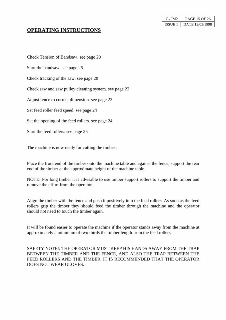
Control panel functions:- a. ‘STOP’ button MAIN MOTOR FOR BANDSAW. b. ‘START’ button MAIN MOTOR FOR BANDSAW. c. ‘STOP’ button FEED MOTOR FOR FEEDWHEELS. d. ‘START’ button FEED MOTOR FOR FEEDWHEELS. e. ‘CONTROL’ button SPEED OF FEEDWHEELS. g. ‘RESET’ button FEED CONTROL RESET. h. ‘STOP’ button EMERGENCY STOP. j. ‘CONTROL’ button TRACKING SWITCH (ON DC BRAKING MACHINES ONLY). l. ‘BRAKING AVAILABLE’ light BRAKING SYSTEM LIGHT.
ST9 / IM2 PAGE 18 OF 26 ISSUE 1 DATE 13/05/1998
CONTROL PANEL (For machines with D.C. Braking).
BRAKINGAVAILABLE
FEED RESET
STOP
START
MAINMOTOR
STOP
START
FEEDMOTOR
RUN SAW TRACK 9
g
h
a c
b d
e j
l
ST9 PUSH BUTTON LAYOUT (STARTER) DRAWING No. A2/65782

ST9 / IM2 PAGE 18a OF 26 ISSUE 1 DATE 13/05/1998
BRAKE MONITORING SYSTEM
OPERATORS GUIDANCE
This machine is fitted with an Electric D.C. Braking System. Under normal running conditions the ‘Brake Monitoring System’ light will be on to indicate that there is power available to the braking system. Variances to the above are shown in the chart below.
LIGHT CONDITION
On In run mode - normal condition Off Track mode - normal condition (for 2 minutes) On Track mode -
Emergency stop operated. Guard open. Allowed tracking time has been exceeded and braking is taking place.
If at any time the light is on when the saw is running and the braking has not operated when saw is stopping, this is evidence of a fault condition and a qualified electrician should be called to rectify the fault using the ‘Fault Chart’ below. The machine should not be used under these conditions. If at any time during normal running the ‘Brake Monitoring System’ light is off then a fault condition exists and a qualified electrician should be called to rectify the fault using the ‘Fault Chart’ below. The machine should not be used under these conditions.
FAULT CHART LIGHT CONDITION CHECK
On Run mode, Braking failed to operate.
Operation and contacts of R51, R52, 1K4. Auxiliary contacts on 1K1M
On Run mode, Unable to start.
“A-Stop” relay BRD13G R1A Emergency stops. Guard switch. Saw motor overload.
Off Run mode, Unable to start.
110V control circuit supply. Run/track switch.
Off Run mode,
Saw runs and stops correctly.
Bulb.

ST9 / IM2 PAGE 19 OF 26 ISSUE 1 DATE 13/05/1998
SETTING INSTRUCTIONS.
FITTING THE BANDSAW
Make sure the pulley's are not rotating and the isolator is switched to the "off" position.
Open the main door (at rear of machine).
Open the saw cleaning pads.
Remove the slot filler (in the top of the machine table)
Lower the adjustable pulley (if necessary) by rotating the tension screw with ratchet clockwise.
Ensure the rims of the saw pulleys and both sides of the bandsaw are clean.
Slide the saw, with the "teeth" facing away from the operator, on to the pulleys, adjustable pulley first, taking care not to damage the saw teeth, and position the saw with it's gullets projecting approximately 3mm (1/8") from the front rim of the pulleys.
Raise the adjustable pulley by rotating the tensioning screw with ratchet anti-clockwise until the required bandsaw tension is applied. Refer to section headed, Tensioning the Bandsaw.
Close the saw cleaning pads.
Replace the slot filler and close and secure the main door.
Run in a new bandsaw, see section headed, Guide to Good Sawing with Wide Bandsaws (page G1).

ST9 / IM2 PAGE 20 OF 26 ISSUE 1 DATE 13/05/1998
TENSIONING THE BANDSAW
Open the main door.
Raise the adjustable pulley by rotating the tensioning screw with ratchet anti-clockwise until the required bandsaw tension is indicated by the rod on the tension scale, situated just above the tensioning screw and ratchet.
For the recommended tension, refer to the saw straining plate situated on the inside of the main door, or see page 21.
As a general guide use the minimum of tension consistent with straight sawing.
Close the main door.
Run the saw and check the tension is correct. Adjust if necessary.
NOTE!! Do not run the saw unless there is some tension in the bandsaw blade.
IMPORTANT. WHEN THE MACHINE IS NOT IN USE, LOWER THE ADJUSTABLE PULLEY UNTIL NO STRAIN IS REGISTERED ON THE SCALE.
TRACKING THE BANDSAW
Run the saw pulleys a few revolutions, then either ;
a) See “Starting The Bandsaw” Page 25, but 3½ seconds after pressing button ‘b’ press ‘a’.Or
b) If the machine is fitted with a brake turn the tracking switch ‘j’ to the tracking modewhich will prevent operation of the brake. Press and hold button ‘b’ to start the pulleys rotating. Releasing button ‘b’ will remove the drive from the pulleys, but will not stop the pulleys.
The bandsaw should run with the bottom of the saw gullets over hanging the front of the rim of the adjustable pulley.
(To assist tracking on the ST9 two brass pins are fixed in the table top near the slot filler, the edge of the gullets should align with the left hand side of the pins.)
Turn the tracking handwheel slowly as the saw position on the pulley moves quickly. Turn the handwheel clockwise to increase the saw overhang and anti-clockwise to decrease the overhang.
Briefly run the pulley and check tracking. Adjust if required, remembering to check tension.
The saw may now be run at full speed.
DO NOT ALLOW THE SAW TEETH TO RUN ON THE PULLEY FACES AS THIS WILL FLATTEN ONE SIDE OF THESWAGED TEETH, SCORE THE PULLEYS AND MAKE THE SAW PULL TO ONE SIDE IN THE CUT. CHECK THE SAW ISNOT BEING PUSHED BACK ON THE PULLEYS WHEN MAKING DEEP CUTS.
ST9 / IM2 PAGE 21 OF 26 ISSUE 1 DATE 13/05/1998
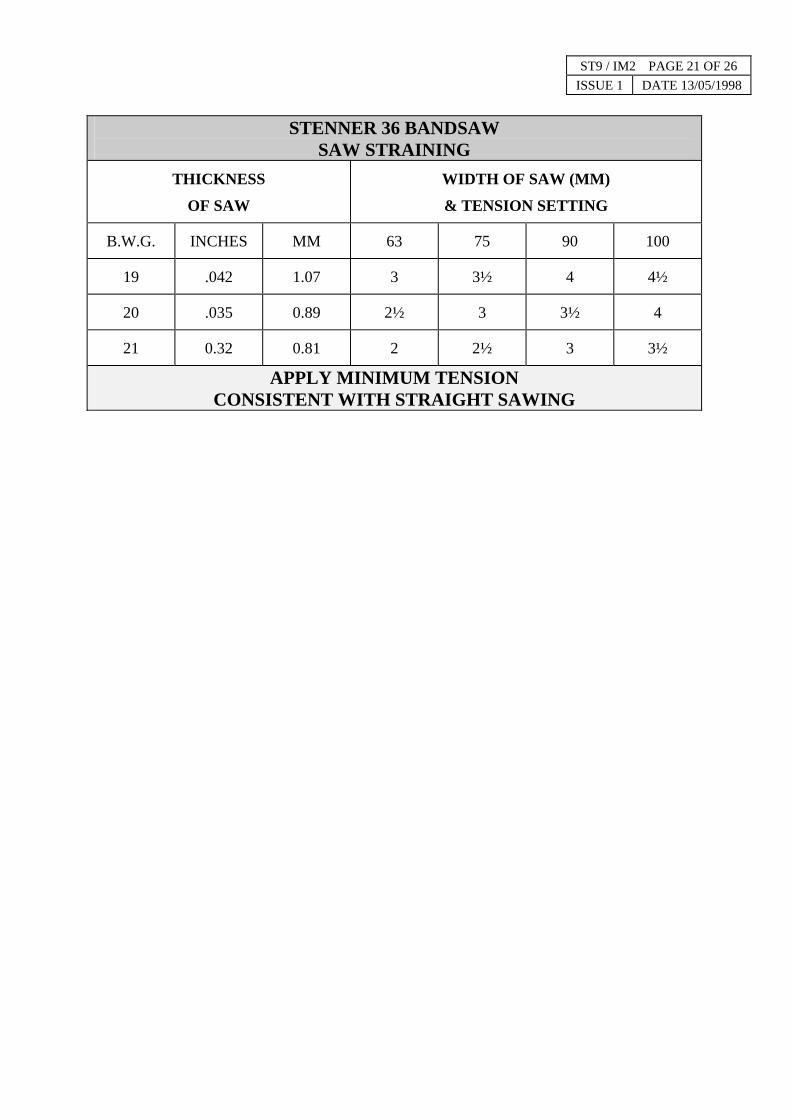
STENNER 36 BANDSAW
SAW STRAINING THICKNESS
OF SAW WIDTH OF SAW (MM)
& TENSION SETTING
B.W.G. INCHES MM 63 75 90 100
19 .042 1.07 3 3½ 4 4½
20 .035 0.89 2½ 3 3½ 4
21 0.32 0.81 2 2½ 3 3½
APPLY MINIMUM TENSION CONSISTENT WITH STRAIGHT SAWING

ST9 / IM2 PAGE 22 OF 26 ISSUE 1 DATE 13/05/1998
SAW AND SAW PULLEY CLEANING SYSTEM Before the saw is run at full speed the saw pulley cleaning system must be primed and set. Fill the oil reservoir with diesel oil. The filler cap is situated on top of the machine. Pour a small quantity of diesel oil onto the top and bottom pulley pads and the saw cleaning pads sufficient to initially impregnate the felt. Under no circumstances run the saw at speed with dry pads. The three oil drip feed control valves are situated on the right hand outside wall of the machine. Adjust each valve to give a drip rate of approximately 1 drop per 10 seconds. Further adjustment may be necessary if flooding occurs or felt pads or pressure guide pads become dry. A lever tap is fitted near the tracking handwheel to turn the lubrication system on and off. Remember to turn system off when not using machine to prevent loss of lubrication from system . Do not continue to run the machine when reservoir is visibly low of lubricant. Use protective gloves when handling this lubricant. SAWGUIDES These machines are fitted with pressure sawguides. Accurate sawing relies on keeping the replaceable sawguide pads in good condition. When a sawblade is first used on new pads the saw teeth will cut a groove in the surface of the pads: this is normal. Thereafter the saw will run on the low friction pads with minimal wear provided a thin film of lubrication is maintained between saw and pads, (see section on saw and pulley cleaning system). When noticeable wear is evident both pads should be replaced. After the saw has been removed tap out the worn pads from the dovetailed holders. Wipe clean the holders. Fit new pads and ensure the surfaces of the pads are smooth and free of dirt before replacing the saw.
ST9 / IM2 PAGE 23 OF 26 ISSUE 1 DATE 13/05/1998
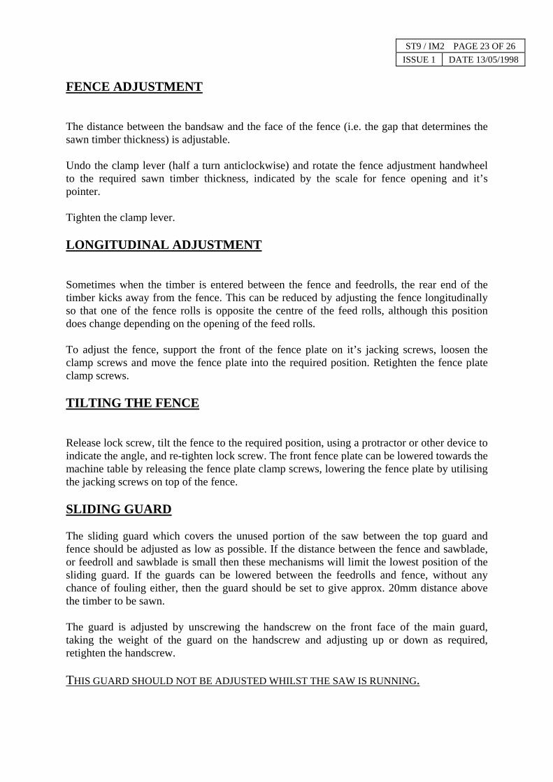
FENCE ADJUSTMENT
The distance between the bandsaw and the face of the fence (i.e. the gap that determines the sawn timber thickness) is adjustable.
Undo the clamp lever (half a turn anticlockwise) and rotate the fence adjustment handwheel to the required sawn timber thickness, indicated by the scale for fence opening and it’s pointer.
Tighten the clamp lever.
LONGITUDINAL ADJUSTMENT
Sometimes when the timber is entered between the fence and feedrolls, the rear end of the timber kicks away from the fence. This can be reduced by adjusting the fence longitudinally so that one of the fence rolls is opposite the centre of the feed rolls, although this position does change depending on the opening of the feed rolls.
To adjust the fence, support the front of the fence plate on it’s jacking screws, loosen the clamp screws and move the fence plate into the required position. Retighten the fence plate clamp screws.
TILTING THE FENCE
Release lock screw, tilt the fence to the required position, using a protractor or other device to indicate the angle, and re-tighten lock screw. The front fence plate can be lowered towards the machine table by releasing the fence plate clamp screws, lowering the fence plate by utilising the jacking screws on top of the fence.
SLIDING GUARD
The sliding guard which covers the unused portion of the saw between the top guard and fence should be adjusted as low as possible. If the distance between the fence and sawblade, or feedroll and sawblade is small then these mechanisms will limit the lowest position of the sliding guard. If the guards can be lowered between the feedrolls and fence, without any chance of fouling either, then the guard should be set to give approx. 20mm distance above the timber to be sawn.
The guard is adjusted by unscrewing the handscrew on the front face of the main guard, taking the weight of the guard on the handscrew and adjusting up or down as required, retighten the handscrew.
THIS GUARD SHOULD NOT BE ADJUSTED WHILST THE SAW IS RUNNING.

ST9 / IM2 PAGE 24 OF 26 ISSUE 1 DATE 13/05/1998
FEED ROLLERS
The gap between the feed rollers and the bandsaw is adjusted by rotating the feed roller handwheel.
Set the gap smaller than the thickness of the timber to be cut so that the rollers climb the timber and are pushed back when cutting, thus maintaining pressure on the timber.
Note! The rollers will not climb more than 50 mm.
The height of the feed rollers should be adjusted to suit the size and shape of the timber to be sawn.
Remove the feed roller guard by lifting vertically upwards.
Reposition the feed rollers on their drive shaft by releasing the cap screw in each roller. Retighten screw .
If required the feed rollers may be removed by this method and replaced with feed rollers of a different type.
Always refit the feed roller guard.
FEED SPEED
To change the speed of the feed wheels. Use control knob (e), see page 16 and 17.
Setting no 1 gives 7.5m/min (25ft/min)
Setting no 10½ gives 30m/min (lOOft/min)

ST9 / IM2 PAGE 25 OF 26 ISSUE 1 DATE 13/05/1998
STARTING THE BANDSAW FOR CUTTING
(Key letters refer to the switches on the control box. Pages 16, 17 & 18.)
(For machines fitted with automatic star delta starters, the starting procedure is as follows.)
1. ENSURE THAT TENSION HAS BEEN APPLIED AND TRACKING IS CORRECT.
2. ENSURE THAT GUARDS ARE SECURE AND SAFETY PROCEDURES ADHERED TO.
3. TURN THE ISOLATING SWITCH (F) TO THE ON POSITION.
4. ENSURE EMERGENCY STOP BUTTONS ARE “PULLED OUT”.
5. ENSURE THE TRACKING SWITCH (J) IS IN THE RUN POSITION (WHERE FITTED).
6. PUSH THE START BUTTON (B).
7. WHEN BANDSAW IS RUNNING AT FULL SPEED PRESS BUTTON (D) TO START FEED ROLLERS.
8. TO STOP THE MAIN MOTOR PUSH STOP BUTTON (A). THIS WILL ALSO STOP THE FEED ROLLERS.
9. TO STOP THE FEED ROLLERS ONLY, PUSH STOP BUTTON (C).
10. THE EMERGENCY STOPS (H) FITTED AT THE CONTROL BOX (INFEED AND OUTFEED POSITIONS)WILL STOP BOTH THE FEED MOTOR AND MAIN MOTOR, AND THE BUTTON WILL REMAIN LATCHED-IN. TO RELEASE THESE BUTTONS TURN ANTICLOCKWISE AND PULL OUT.
11. AN INTERLOCK IS FITTED TO THE MAIN DOOR WHICH WILL PREVENT THE MACHINE FROMSTARTING WHEN THE DOOR IS OPEN. IT WILL ALSO STOP THE MACHINE IF THE DOOR IS OPENEDWHILST THE MACHINE IS RUNNING. THIS SWITCH DOES NOT REQUIRE ANY ADJUSTMENT.
12. THE D.C. BRAKE OPERATES WHENEVER THE MACHINE IS STOPPED, EXCEPT WHEN THE MODESWITCH IS SET TO TRACKING MODE. IF THE EMERGENCY STOPS ARE OPERATED, OR THE MAINDOOR IS OPENED DURING ‘TRACKING’ THE BRAKE WILL OPERATE. THE BRAKE DOES NOTREQUIRE ANY ADJUSTMENT. THE “BRAKING AVAILABLE” LIGHT (L) IS ON WHEN THE BRAKINGSYSTEM IS IN GOOD WORKING ORDER. IF THIS LIGHT SHOULD NOT BE ON AT ANY TIME HAVE THEBRAKING SYSTEM CHECKED BY AN ELECTRICIAN.
WARNING- THE ISOLATOR MUST NOT BE USED FOR STOPPING THE MACHINE - BRAKING WILLNOT BE AVAILABLE. THE STOP BUTTON MUST BE USED FOR STOPPING THE MACHINE.THE ISOLATOR MUST NOT BE SWITCHED OFF UNTIL THE MACHINE HAS COME TO REST. IF THE ELECTRICAL POWER SUPPLY FAILS, BRAKING WILL NOT BE AVAILABLE.
IMPORTANT- WHENEVER THE MACHINE IS STOPPED TURN ISOLATING SWITCH TO THE OFF POSITION.

CUTTING WIDE BOARDS
The feed roller assembly may be removed completely to allow wide boards or sheet materials to be sawn by hand feeding.
Remove the feed roller guard by lifting vertically upwards.
Remove feed roller handwheel.
Remove the feed drive cover at the front of the machine (4 screws).
Inside this cavity, remove the M12 cap screw (10 A/F hexagon key) together with its washer from the underside of the feed wheel drive shaft.
The feed wheels together with their drive shaft can now be lifted vertically upwards out of the feed drive gearbox.
Replace the feed drive cover and feed roller handwheel before starting the machine.
To refit the feed roller assembly:
Remove the feed drive cover.
Slide the drive shaft (with its feed wheels) down into the feed drive gearbox (through the top of the base), taking care to align the key in the shaft with the keyway in the gearbox.
Fit and tighten the M12 cap screw with its washer, into the underside of the feed wheel drive shaft.
Replace feed drive cover and feed roller guard before starting the machine.
ANGLED CUTTING
Tilt the fence to the required angle, see page 23. It is recommended that a rubber covered feed roller is used when angle cutting to provide point contact on the feed roll side of the timber without marking the timber.
Having tilted the fence as above adjust and operate the machine as previously described.
NOTE.
FOR 45º CUTTING A SPECIAL FEEDROLL Z11269 IS AVAILABLE, AND WHEN USED WITH A TABLE JIG ENABLES THIS OPERATION TO BE PERFORMED. CONTACT STENNER FOR ADVICE.
ST9 / IM2 PAGE 26 OF 26 ISSUE 1 DATE 13/05/1998

DRIVEN PULLEY ASSEMBLY
ST9 / PM2 PAGE 1 OF 20 ISSUE 1 DATE 13/05/98
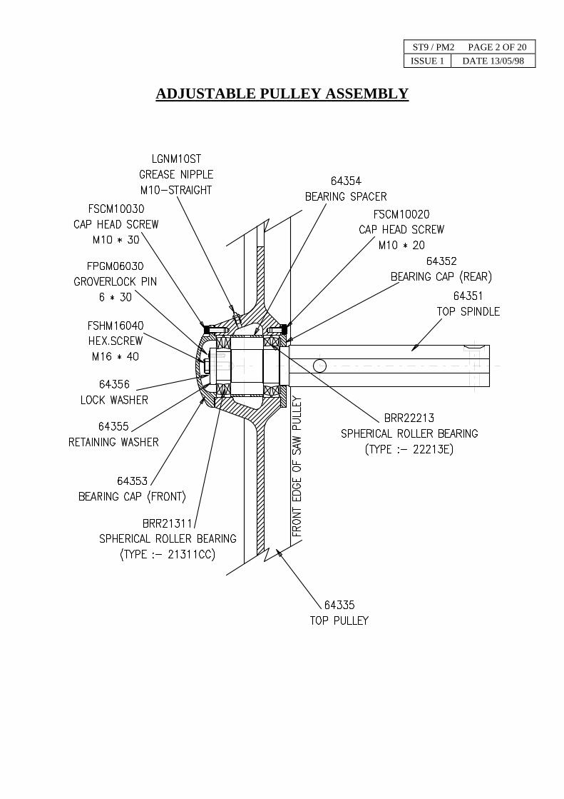
ADJUSTABLE PULLEY ASSEMBLY
ST9 / PM2 PAGE 2 OF 20 ISSUE 1 DATE 13/05/98

ST9 / PM2 PAGE 3 OF 20 ISSUE 1 DATE 13/05/98
TOP COLUMN ASSEMBLY

FENCE ASSEMBLY
ST9 / PM2 PAGE 4 OF 20 ISSUE 1 DATE 13/05/98
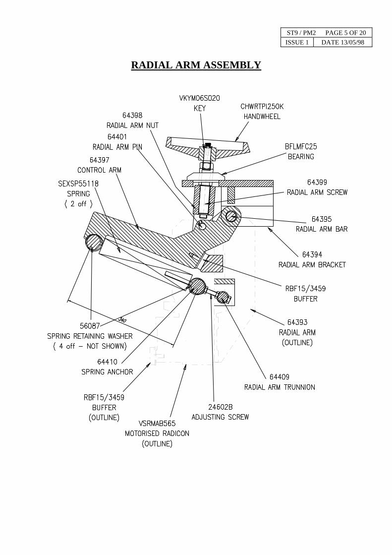
RADIAL ARM ASSEMBLY
ST9 / PM2 PAGE 5 OF 20 ISSUE 1 DATE 13/05/98

MAIN ASSEMBLY
ST9 / PM2 PAGE 6 OF 20 ISSUE 1 DATE 13/05/98

PADS & SCRAPERS
ST9 / PM2 PAGE 7 OF 20 ISSUE 1 DATE 13/05/98
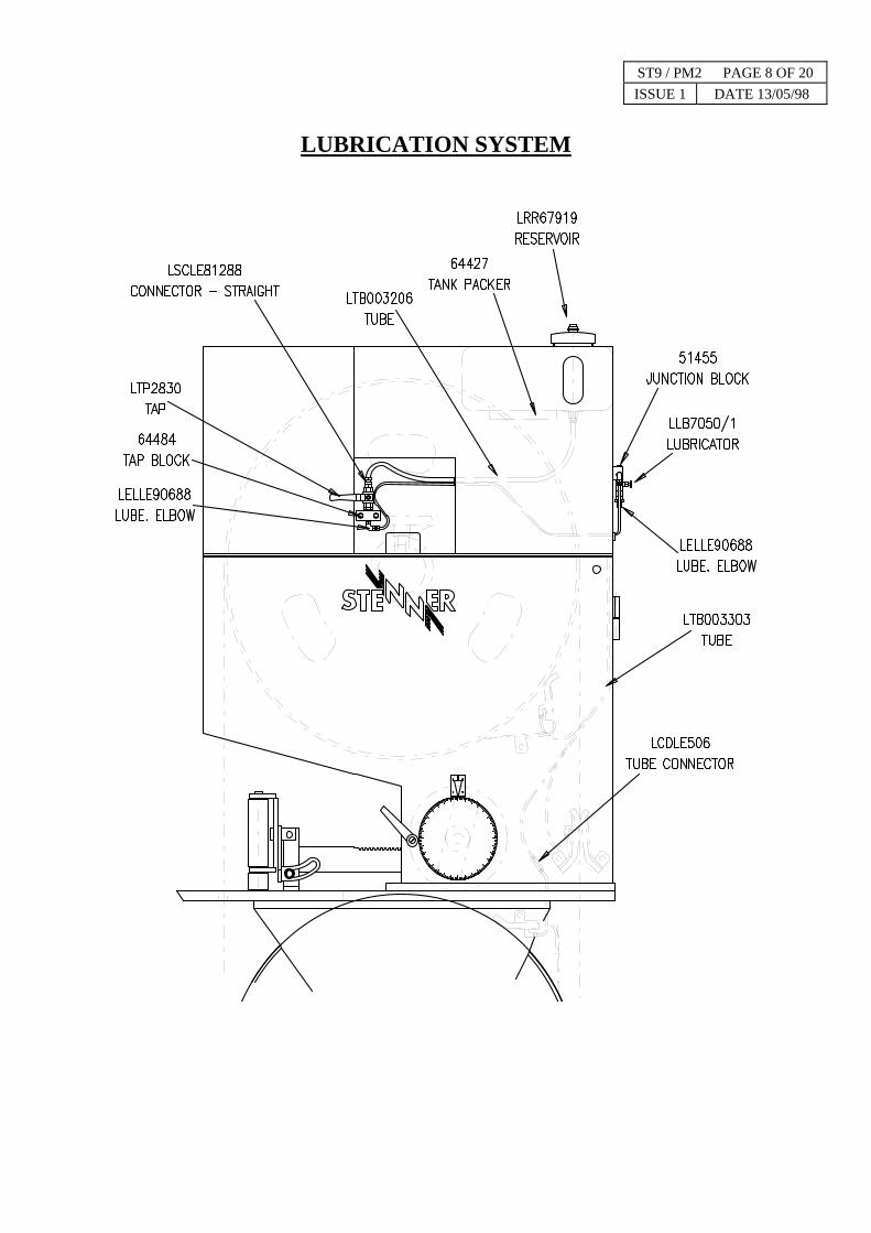
LUBRICATION SYSTEM
ST9 / PM2 PAGE 8 OF 20 ISSUE 1 DATE 13/05/98

Critical Safety Related Electrical Components. For 380/440V Supply
(See page 18 for button references.)
ST9 / PM2 PAGE 9 OF 20 ISSUE 1 DATE 13/05/98
EAB11P1/P3 ISOLATOR Q CONTACT(AUX.) HI11-P1/P3Z
EAB22DILM R53, 1K1M, 2K1M, 1K5M, 1K3M, 1K4 CONTACT BLOCK(AUX.)22DILM
EBPA-22KWCE 1P, R1A, R52 BRAKING(DC-22KW PACK)CEN
ECB020 (button j) RUN/TRACK SELECTOR SWITCH CONTACT BLOCK ZB2-BE102
ECB060 (button j) RUN/TRACK SELECTOR SWITCH CONTACT BLOCK ZB2-BZ105
ECBBK11 (buttons c, d) FEED STOP/START, MAIN MOTOR STOP/START
CONTACT BLOCK BK11
ECBEC20 (buttons a,b) MAIN MOTOR STOP/START CONTACT(BLOCK) EC20
ECMFAZS162 2F1 CIRC BREAKER FAZS16-2
ECMFAZS4 CONTROL TRANSFORMER SECONDARY CIRC BREAKER FAZS4
ECMFAZS42 CONTROL TRANSFORMER PRIMARY CIRC BREAKER FAZS4-2
ECR00M110 2K1M CONTACTOR DIL00M 110V
ECR0AM110 1K1M, 1K5M, 1K3M CONTACTOR DIL0AM 110V
ECR2M110 1K4 CONTACTOR DIL2M 110V
EGA210H FEED MOTOR INVERTER DRIVE CONTROLLER .75K J100 007SFE
EIMMVDILM MAIN MOTOR STAR/DELTA INTERLOCK (MECH) MVDILM
EISP363V ISOLATOR Q ISOLATOR P3-63/v/Svb
EOLZ140 F1 OVERLO4D Z1-40
EPBPV (button h) EMERGENCY STOP PUSH BUTTON RPV
EPBQDD1110 (buttons c,d) MAIN MOTOR, FEED MOTOR PUSH BN ACTUATOR QDD11/1
EPBZB2BW36 (button g) FEED INVERTER RESET PUSH BUTTON ZB2-BW36
EPBZB2BW65 (button g) FEED INVERTER RESET PUSH BTN BODY ZB2-BW065
ERH173057 (button e) FEED CONTROL SPEED REFERENCE RHEOSTAT(POT) 1k OHMS*3W
ERYR22110 R53, K3T, K3T, R51 RELAY DILR22 110V
ESL070 GUARD INTERLOCK SWITCH(LMT)XCLB16 DL3
ESRZB2BJ2 (button j) RUN TRACK SELECTOR SWITCH SWITCH(SELECTOR)ZB2-BJ2
ETF0100 110V CONTROL TRANSFORMER TRANSFORMER 100VA
ETM060 1K1T, K2T, K3T, K4T TIMER TPE11DILR
65973 GUARD INTERLOCK CAM(SAFETY SWITCH)

Critical Safety Related Electrical Components. For 220/240V Supply
(See page 18 for button references.)
ST9 / PM2 PAGE 10 OF 20 ISSUE 1 DATE 13/05/98
EAB11P1/P3 ISOLATOR Q CONTACT(AUX.) HI11-P1/P3Z
EAB22DILM R53, 1K1M, 2K1M, 1K5M, 1K3M, 1K4 CONTACT BLOCK(AUX.)22DILM
EBPA-22KWCE 22 1P, R1A, R52 BRAKING(DC-22KW PACK)CEN
ECB020 (button j) RUN/TRACK SELECTOR SWITCH CONTACT BLOCK ZB2-BE102
ECB060 (button j) RUN/TRACK SELECTOR SWITCH CONTACT BLOCK ZB2-BZ105
ECBBK11 (buttons c, d) FEED STOP/START, MAIN MOTOR STOP/START
CONTACT BLOCK BK11
ECBEC20 (buttons a,b) MAIN MOTOR STOP/START CONTACT(BLOCK) EC20
ECMFAZS162 2F1 CIRC BREAKER FAZS16-2
ECMFAZS4 CONTROL TRANSFORMER SECONDARY CIRC BREAKER FAZS4
ECMFAZS42 CONTROL TRANSFORMER PRIMARY CIRC BREAKER FAZS4-2
ECR00M110 2K1M CONTACTOR DIL00M 110V
ECR2M110 1K1M, 1K5M, 1K3M, 1K4 CONTACTOR DIL0AM 110V
EGA210H FEED MOTOR INVERTER DRIVE CONTROLLER .75K J100 007SFE
EIMMVDILM MAIN MOTOR STAR/DELTA INTERLOCK (MECH) MVDILM
EISP3100V ISOLATOR Q ISOLATOR P3-63/v/Svb
EOLZ157 F1 OVERLO4D Z1-40
EPBPV (button h) EMERGENCY STOP PUSH BUTTON RPV
EPBQDD1110 (buttons c,d) MAIN MOTOR, FEED MOTOR PUSH BN ACTUATOR QDD11/1
EPBZB2BW36 (button g) FEED INVERTER RESET PUSH BUTTON ZB2-BW36
EPBZB2BW65 (button g) FEED INVERTER RESET PUSH BTN BODY ZB2-BW065
ERH173057 (button e) FEED CONTROL SPEED REFERENCE RHEOSTAT(POT) 1k OHMS*3W
ERYR22110 R53, K3T, K3T, R51 RELAY DILR22 110V
ESL070 GUARD INTERLOCK SWITCH(LMT)XCLB16 DL3
ESRZB2BJ2 (button j) RUN TRACK SELECTOR SWITCH SWITCH(SELECTOR)ZB2-BJ2
ETF0100 110V CONTROL TRANSFORMER TRANSFORMER 100VA
ETM060 1K1T, K2T, K3T, K4T TIMER TPE11DILR
65973 GUARD INTERLOCK CAM(SAFETY SWITCH)
ERY170961 RELAY ROTATION SENSING. RRS RELAY 170-961
ESLNPNFPS PROXIMITY SWITCH. FOR RRS. PROXIMITY SWITCH NPNFPS
ST9 / PM2 PAGE 11 OF 20 ISSUE 1 DATE 13/05/98
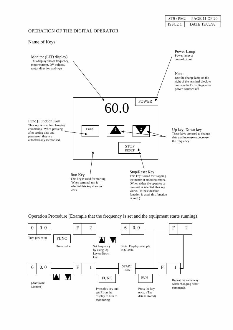
OPERATION OF THE DIGITAL OPERATOR Name of Keys
60.0
Operation Procedure (Example that the frequency is set and the equipment st
POWER
Monitor (LED display) This display shows frequency, motor current, DV voltage, motor direction and type
2 1 FUNC
STOP RESET
Stop/Reset Key This key is used for stopping the motor or resetting errors. (When either the operator or terminal is selected, this key works. If the extension function is used, this function is void.)
Func (Function Key This key is used for changing commands. When pressing after setting data and parameter, they are automatically memorised.
Run Key This key is used for starting. (When terminal run is selected this key does not work
Turn power on
0 0 0
FUNC
F 2 6 0. 0
F 1 START RUN
0. 0 6 F
FUNC RUN
(Automatic Monitor) Press this key and
get F1 on the display to turn to monitoring
Press the key once. (The data is stored)
Power LampPower lamp of control circuit
arts running)
Note: Use the charge lamp on the right of the terminal block to confirm the DC voltage after power is turned off
Up key, Down key These keys are used to change data and increase or decrease the frequency
F 2
Set frequency Note: Display exampleby using Up is 60.0Hz key or Down key
Press twice
1
Repeat the same way when changing other commands
ST9 / PM2 PAGE 12 OF 20 ISSUE 1 DATE 13/05/98
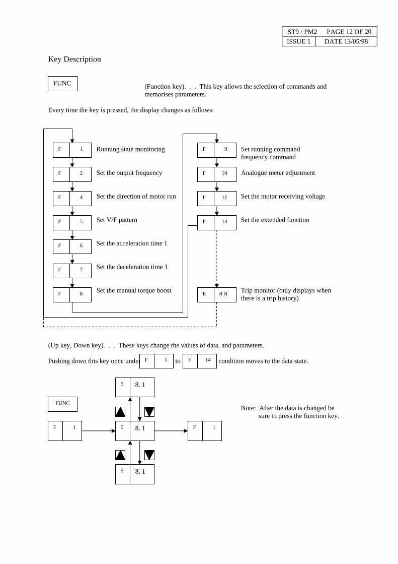
Key Description
(Function key). . . This key allows the selection of commands and memorises parameters.
Every time the key is pressed, the display changes as follows:
Running state monitoring Set running command frequency command
Set the output frequency Analogue meter adjustment
Set the direction of motor run Set the motor receiving voltage
Set V/F pattern Set the extended function
Set the acceleration time 1
Set the deceleration time 1
Set the manual torque boost Trip monitor (only displays when there is a trip history)
(Up key, Down key). . . These keys change the values of data, and parameters.
Pushing down this key once under to condition moves to the data state.
Note: After the data is changed be sure to press the function key.
FUNC
F 1
F 2
F 4
F 5
F 6
F 7
F 8
F 9
F 10
F 11
F 14
E R R
1 F 14 F
5
FUNC
8. 1 5 1 F 1 F
8. 1
8. 1 5

ST9 / PM2 PAGE 13 OF 20 ISSUE 1 DATE 13/05/98
(Run key). . . This key starts the run.
The set value of determines a forward run or reverse run
(Stop Reset key). . . This key stops the run.
When a trip occurs, this key becomes the reset key.
Screen Transfer For Extended Commands
When an extended command is to be used, select the extended function command number from
by using the keys and so as to enter the extended function mode.
Explanation Of Screen Display
RUN
4 F
STOP RESET
14 F
F
1
24 A 24
FUNC
0
14
Extended function setting command
0 (In the case of the command A)
Extended function command display
0 .
In the case of the command C, the decimal point in the high order position lights like
FUNC
FUNC
1. When the inverter is turned on, the display that is outputted when the power is turned off before it isturned on appears. However, when the data display section for the commands F4 to F14 is turned off,the command display (F4 to F14) at that time appears.
2. At the time of second setting, the decimal point in the first section is displayed likeHowever, a display of more than a 100 of the set frequency, acceleration and deceleration time, DC braking time adjustment time, or standby time after under voltage does not mean the second setting.
22

ST9 / PM2 PAGE 14 OF 20 ISSUE 1 DATE 13/05/98
Appendix 1 J100 Series Data Setting Values J100 series inverters provide many functions and their parameters can be set by the user. It is recommended to record the parameters that have been set by the user, in order to speed the investigation and repair in the event of a failure. Inverter model J100
MFG. No.
For the digital operator
}This information is written on the name plate located on the side cover of the inverter.
Display Sequence Function Name Standard Setting Set Value
F1 Setting frequency and output frequency - F2 Setting output frequency 0.0 F4 Direction of the motor revolution F F5 Setting V/F pattern 08 (00) 08 F6 Setting acceleration time 10.0 (15.0) 1.5 F7 Setting deceleration time 10.0 (15.0) 1.0 F8 Setting torque boost 11 F9 Switch over of the digital operator and
terminal mode 03
F10 Analogue meter adjustment 72 F11 Setting input voltage 220 (380) F14 Setting extension function 0
NOTE: The value in the parentheses is for 400 V.

ST9 / PM2 PAGE 15 OF 20 ISSUE 1 DATE 13/05/98
(2) Extension Function Mode
Command Display Function Name Standard Setting Remarks
A0 Control method 0 1 A1 Motor capacity setting Note 1 0.75 A2 Motor poles setting 4 A3 Maximum frequency adjustment 0.0 A4 Start frequency adjustment 0.5 A5 Upper frequency limiter setting 0 A6 Lower frequency limiter setting 0 A7 Jump frequency setting 1 0 A8 Jump frequency setting 2 0 A9 Jump frequency setting 3 0 A10 Carrier frequency setting 16 05 A11 Frequency command sampling setting 8 A12 Multispeed first speed setting 0 A13 Multispeed second speed setting 0 A14 Multispeed third speed setting 0 A15 Multispeed fourth speed setting 0 A16 Multispeed fifth speed setting 0 A17 Multispeed six speed setting 0 A18 2-stage acceleration time setting 10.0 A19 2-stage deceleration time setting 10.0 A20 DC braking frequency setting 0.5 A21 DC braking force adjustment 0 A22 DC braking time adjustment 0 A23 Electronic thermal level adjustment 100 A24 Electronic thermal characteristic selection 1 A26 External frequency setting start 0 25 A27 External frequency setting end 0 105 A28 Acceleration selection (Linear, S-curve) 0 A29 Deceleration selection (Linear, S-curve) 0 A30 Overload previous notice signal setting 150 A31 Overload limit level setting 150 A32 Overload limit content selection 0 A33 LAD stop function setting 0 A34 Trip/retry function selection 0 A35 Trip ignorance selection 0 A36 AVR voltage setting for deceleration 0 A37 Motor voltage setting for deceleration 220 (380) A38 Dynamic braking usage ratio 5 A39 Optional arrival frequency for
acceleration 100

ST9 / PM2 PAGE 16 OF 20 ISSUE 1 DATE 13/05/98
Command Display Function Name Standard Setting Remarks
A40 Optional arrival frequency for deceleration 100 A41 Forward rotation 1 A42 Reverse rotation 1 A43 Stop key ON/OFF selection 0 A48 Analogue input selection 0 A49 Frequency arrival signal output method 2 A50 Analogue/digital meter selection 1 A51 Frequency/current monitoring selection 0 A52 RUN signal output selection 1 A53 Enable/disable of frequency setting for software lock 0A55 DC braking ON/OFF selection 0 A56 DC braking edge/level selection 1 A57 Trip history clear selection 0 A58 Reduced voltage start selection 1 A62 Base frequency setting 50 A63 Maximum frequency setting 50 105 A64 Maximum frequency switching 0 A68 Jump frequency range setting 0.5 A71 Multispeed seventh speed setting 0 A80 Frequency command adjust. (voltage) NOTE 2 A81 Frequency command adjust. (current) NOTE 2 A82 Allowable undervoltage time setting 1.0 A83 Undervoltage retry waiting time 10.0 A84 Software lock selection 0 A85 Deceleration rate setting for overload limit 1.0 C0 Input terminal setting 1 1 C1 Input terminal setting 2 2 C2 Input terminal setting 3 7 C3 Input terminal setting 4 11 C4 Input terminal setting 5 0 C10 Output terminal setting 0 C20 Input terminal a and b contact setting 00 C21 Output terminal a and b contact setting 03
NOTE 1: The most applicable motor capacity of the inverter is set. NOTE 2: The initial setting of each inverter is adjusted when shipped from the factory. NOTE 3: The value in the parentheses is for 400V standard setting.

ANNEX A
ST9 / PM2 PAGE 17 OF 20 ISSUE 1 DATE 13/05/98

ST9 M/c No AN9935
Noise Test to ISO7960
ST9 / PM2 PAGE 18 OF 20 ISSUE 1 DATE 13/05/98
Pulley Diameter 0.914M
Pulley Rpm 615 rpm
Saw Speed 29.4M/sec
Blade Width 100mm
Tooth Pitch 38mm
Blade Thickness 20 gauge (0.9mm)
Feed Speed 15M/min
Timber Softwood
Length 2M
Depth Of Cut 150mm
Fence Set At 25mm
PROCESS FROM 150MM WIDE UNTIL 50MM REMAINS

NOISE TEST POSITIONS FOR ST9
ST9 / PM2 PAGE 19 OF 20 ISSUE 1 DATE 13/05/1998
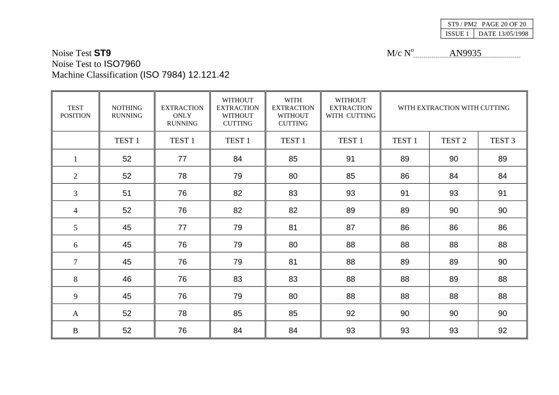
Noise Test ST9 M/c No AN9935 Noise Test to ISO7960 Machine Classification (ISO 7984) 12.121.42
TEST POSITION
NOTHING RUNNING
EXTRACTION ONLY
RUNNING
WITHOUT EXTRACTION
WITHOUT CUTTING
WITH EXTRACTION
WITHOUT CUTTING
WITHOUT EXTRACTION
WITH CUTTING
WITH EXTRACTION WITH CUTTING
TEST 1 TEST 1 TEST 1 TEST 1 TEST 1 TEST 1 TEST 2 TEST 3
1 52 77 84 85 91 89 90 89
2 52 78 79 80 85 86 84 84
3 51 76 82 83 93 91 93 91
4 52 76 82 82 89 89 90 90
5 45 77 79 81 87 86 86 86
6 45 76 79 80 88 88 88 88
7 45 76 79 81 88 89 89 90
8 46 76 83 83 88 88 89 88
9 45 76 79 80 88 88 88 88
A 52 78 85 85 92 90 90 90
B 52 76 84 84 93 93 93 92
ST9 / PM2 PAGE 20 OF 20 ISSUE 1 DATE 13/05/1998

ST9 / INX2 PAGE 1 OF 1 ISSUE 1 DATE 13/05/1998
INDEX
This manual should contain the following pages:-
Pages 1 to 26 (inclusive).
Pages G1 to G6 (inclusive).
Maintenance Schedule MS 0/1
Maintenance Schedule MS 0/2
Maintenance Schedule MS 18
Maintenance Schedule MS 30
Maintenance Schedule MS 32
Maintenance Schedule MS 53
Maintenance Schedule MS 56
Maintenance Schedule MS 60
PM 2 Pages 1 to 20 (inclusive).
Electrical Diagram No. 66980A.-2 Issue 3
Electrical Diagram No. 66980B-2. Issue 3
Electrical Diagram No. 66076A.-2 Issue 3
Electrical Diagram No. 66076B. Issue 2
Index Page IN1.