ST810 - Advanced Diesel Technology Workbook
119
Initial Print Date: 08/08 Table of Contents Subject Page Advanced Diesel Technology Introduction ...............................................................9 U.S. Market Diesel Introduction ..............................................................................9 A Diesel Engine for North America ........................................................................10 Technical Data Comparison ................................................................................11 Power Output Comparison .................................................................................12 Diesel vs. N52 ..........................................................................................12 Diesel vs. N54 ..........................................................................................12 Comparison to the V8 Engine ............................................................................13 Engine Mechanical ....................................................................................16 Engine Mechanical Changes ...............................................................................16 Bearings ...............................................................................................16 Pistons ................................................................................................16 Crankcase .............................................................................................16 Crankcase Vent .........................................................................................17 Summary of Changes for the M57D30T2 (US) .............................................................18 Vehicle Specific Diesel Changes .......................................................................20 Diesel Vehicles for the US Market ...........................................................................20 Transmission ...........................................................................................20 Twin Damper Torque Converter .......................................................................20 Rear Differential ........................................................................................21 Cooling System ........................................................................................22 Advanced Diesel Technology Revision Date: 09/08
Transcript of ST810 - Advanced Diesel Technology Workbook

Initial Print Date: 08/08
Table of Contents
Subject Page
Advanced Diesel Technology Introduction . . . . . . . . . . . . . . . . . . . . . . . . . . . . . . . . . . . . . . . . . . . . . . . . . . . . . . . . . . . . . . .9U.S. Market Diesel Introduction . . . . . . . . . . . . . . . . . . . . . . . . . . . . . . . . . . . . . . . . . . . . . . . . . . . . . . . . . . . . . . . . . . . . . . . . . . . . . .9A Diesel Engine for North America . . . . . . . . . . . . . . . . . . . . . . . . . . . . . . . . . . . . . . . . . . . . . . . . . . . . . . . . . . . . . . . . . . . . . . . .10
Technical Data Comparison . . . . . . . . . . . . . . . . . . . . . . . . . . . . . . . . . . . . . . . . . . . . . . . . . . . . . . . . . . . . . . . . . . . . . . . . . . . . . . . .11Power Output Comparison . . . . . . . . . . . . . . . . . . . . . . . . . . . . . . . . . . . . . . . . . . . . . . . . . . . . . . . . . . . . . . . . . . . . . . . . . . . . . . . . .12Diesel vs. N52 . . . . . . . . . . . . . . . . . . . . . . . . . . . . . . . . . . . . . . . . . . . . . . . . . . . . . . . . . . . . . . . . . . . . . . . . . . . . . . . . . . . . . . . . . .12Diesel vs. N54 . . . . . . . . . . . . . . . . . . . . . . . . . . . . . . . . . . . . . . . . . . . . . . . . . . . . . . . . . . . . . . . . . . . . . . . . . . . . . . . . . . . . . . . . . .12Comparison to the V8 Engine . . . . . . . . . . . . . . . . . . . . . . . . . . . . . . . . . . . . . . . . . . . . . . . . . . . . . . . . . . . . . . . . . . . . . . . . . . . .13
Engine Mechanical . . . . . . . . . . . . . . . . . . . . . . . . . . . . . . . . . . . . . . . . . . . . . . . . . . . . . . . . . . . . . . . . . . . . . . . . . . . . . . . . . . . .16Engine Mechanical Changes . . . . . . . . . . . . . . . . . . . . . . . . . . . . . . . . . . . . . . . . . . . . . . . . . . . . . . . . . . . . . . . . . . . . . . . . . . . . . . .16Bearings . . . . . . . . . . . . . . . . . . . . . . . . . . . . . . . . . . . . . . . . . . . . . . . . . . . . . . . . . . . . . . . . . . . . . . . . . . . . . . . . . . . . . . . . . . . . . . .16Pistons . . . . . . . . . . . . . . . . . . . . . . . . . . . . . . . . . . . . . . . . . . . . . . . . . . . . . . . . . . . . . . . . . . . . . . . . . . . . . . . . . . . . . . . . . . . . . . . .16Crankcase . . . . . . . . . . . . . . . . . . . . . . . . . . . . . . . . . . . . . . . . . . . . . . . . . . . . . . . . . . . . . . . . . . . . . . . . . . . . . . . . . . . . . . . . . . . . .16Crankcase Vent . . . . . . . . . . . . . . . . . . . . . . . . . . . . . . . . . . . . . . . . . . . . . . . . . . . . . . . . . . . . . . . . . . . . . . . . . . . . . . . . . . . . . . . . .17Summary of Changes for the M57D30T2 (US) . . . . . . . . . . . . . . . . . . . . . . . . . . . . . . . . . . . . . . . . . . . . . . . . . . . . . . . . . . . . .18
Vehicle Specific Diesel Changes . . . . . . . . . . . . . . . . . . . . . . . . . . . . . . . . . . . . . . . . . . . . . . . . . . . . . . . . . . . . . . . . . . . . . . .20Diesel Vehicles for the US Market . . . . . . . . . . . . . . . . . . . . . . . . . . . . . . . . . . . . . . . . . . . . . . . . . . . . . . . . . . . . . . . . . . . . . . . . . . .20Transmission . . . . . . . . . . . . . . . . . . . . . . . . . . . . . . . . . . . . . . . . . . . . . . . . . . . . . . . . . . . . . . . . . . . . . . . . . . . . . . . . . . . . . . . . . . .20
Twin Damper Torque Converter . . . . . . . . . . . . . . . . . . . . . . . . . . . . . . . . . . . . . . . . . . . . . . . . . . . . . . . . . . . . . . . . . . . . . . .20Rear Differential . . . . . . . . . . . . . . . . . . . . . . . . . . . . . . . . . . . . . . . . . . . . . . . . . . . . . . . . . . . . . . . . . . . . . . . . . . . . . . . . . . . . . . . .21Cooling System . . . . . . . . . . . . . . . . . . . . . . . . . . . . . . . . . . . . . . . . . . . . . . . . . . . . . . . . . . . . . . . . . . . . . . . . . . . . . . . . . . . . . . . .22
Advanced Diesel Technology
Revision Date: 09/08

Table of Contents
Subject Page
Cooling Method . . . . . . . . . . . . . . . . . . . . . . . . . . . . . . . . . . . . . . . . . . . . . . . . . . . . . . . . . . . . . . . . . . . . . . . . . . . . . . . . . . . . . . . .23Climate Control for Diesel Vehicles . . . . . . . . . . . . . . . . . . . . . . . . . . . . . . . . . . . . . . . . . . . . . . . . . . . . . . . . . . . . . . . . . . . . . . .24
Front PTC Pin Assignments . . . . . . . . . . . . . . . . . . . . . . . . . . . . . . . . . . . . . . . . . . . . . . . . . . . . . . . . . . . . . . . . . . . . . . . . . .25PTC Heater E90 . . . . . . . . . . . . . . . . . . . . . . . . . . . . . . . . . . . . . . . . . . . . . . . . . . . . . . . . . . . . . . . . . . . . . . . . . . . . . . . . . . . . .25
Acoustic Package . . . . . . . . . . . . . . . . . . . . . . . . . . . . . . . . . . . . . . . . . . . . . . . . . . . . . . . . . . . . . . . . . . . . . . . . . . . . . . . . . . . . . . .26
Diesel Engine Management . . . . . . . . . . . . . . . . . . . . . . . . . . . . . . . . . . . . . . . . . . . . . . . . . . . . . . . . . . . . . . . . . . . . . . . . . . . .28Engine Control Module . . . . . . . . . . . . . . . . . . . . . . . . . . . . . . . . . . . . . . . . . . . . . . . . . . . . . . . . . . . . . . . . . . . . . . . . . . . . . . . . . . . .28Sensors and Actuators . . . . . . . . . . . . . . . . . . . . . . . . . . . . . . . . . . . . . . . . . . . . . . . . . . . . . . . . . . . . . . . . . . . . . . . . . . . . . . . . . .29
OBD Monitored Functions . . . . . . . . . . . . . . . . . . . . . . . . . . . . . . . . . . . . . . . . . . . . . . . . . . . . . . . . . . . . . . . . . . . . . . . . . . . . . . . . .30Diesel Oxidation Catalyst . . . . . . . . . . . . . . . . . . . . . . . . . . . . . . . . . . . . . . . . . . . . . . . . . . . . . . . . . . . . . . . . . . . . . . . . . . . . . . . .30SCR Catalytic Converter . . . . . . . . . . . . . . . . . . . . . . . . . . . . . . . . . . . . . . . . . . . . . . . . . . . . . . . . . . . . . . . . . . . . . . . . . . . . . . . . .30Supplying Urea-water Solution . . . . . . . . . . . . . . . . . . . . . . . . . . . . . . . . . . . . . . . . . . . . . . . . . . . . . . . . . . . . . . . . . . . . . . . . . . .31Level Measurement in Active Reservoir . . . . . . . . . . . . . . . . . . . . . . . . . . . . . . . . . . . . . . . . . . . . . . . . . . . . . . . . . . . . . . . . . . .31Suitable Urea-water Solution . . . . . . . . . . . . . . . . . . . . . . . . . . . . . . . . . . . . . . . . . . . . . . . . . . . . . . . . . . . . . . . . . . . . . . . . . . . . .31NOx Sensors . . . . . . . . . . . . . . . . . . . . . . . . . . . . . . . . . . . . . . . . . . . . . . . . . . . . . . . . . . . . . . . . . . . . . . . . . . . . . . . . . . . . . . . . . . .32Exhaust Gas Recirculation (EGR) . . . . . . . . . . . . . . . . . . . . . . . . . . . . . . . . . . . . . . . . . . . . . . . . . . . . . . . . . . . . . . . . . . . . . . . . .32Diesel Particulate Filter (DPF) . . . . . . . . . . . . . . . . . . . . . . . . . . . . . . . . . . . . . . . . . . . . . . . . . . . . . . . . . . . . . . . . . . . . . . . . . . . .33
Air Intake and Exhaust Systems . . . . . . . . . . . . . . . . . . . . . . . . . . . . . . . . . . . . . . . . . . . . . . . . . . . . . . . . . . . . . . . . . . . . . . . .34Air Intake Systems . . . . . . . . . . . . . . . . . . . . . . . . . . . . . . . . . . . . . . . . . . . . . . . . . . . . . . . . . . . . . . . . . . . . . . . . . . . . . . . . . . . . . . . .36Swirl Flaps . . . . . . . . . . . . . . . . . . . . . . . . . . . . . . . . . . . . . . . . . . . . . . . . . . . . . . . . . . . . . . . . . . . . . . . . . . . . . . . . . . . . . . . . . . . . .37
Exhaust System . . . . . . . . . . . . . . . . . . . . . . . . . . . . . . . . . . . . . . . . . . . . . . . . . . . . . . . . . . . . . . . . . . . . . . . . . . . . . . . . . . . . . . . . . . .38EGR System . . . . . . . . . . . . . . . . . . . . . . . . . . . . . . . . . . . . . . . . . . . . . . . . . . . . . . . . . . . . . . . . . . . . . . . . . . . . . . . . . . . . . . . . . . .38
Fuel System . . . . . . . . . . . . . . . . . . . . . . . . . . . . . . . . . . . . . . . . . . . . . . . . . . . . . . . . . . . . . . . . . . . . . . . . . . . . . . . . . . . . . . . . . .44Fuel Supply Overview . . . . . . . . . . . . . . . . . . . . . . . . . . . . . . . . . . . . . . . . . . . . . . . . . . . . . . . . . . . . . . . . . . . . . . . . . . . . . . . . . . . . .44

Table of Contents
Subject Page
Fuel Tank . . . . . . . . . . . . . . . . . . . . . . . . . . . . . . . . . . . . . . . . . . . . . . . . . . . . . . . . . . . . . . . . . . . . . . . . . . . . . . . . . . . . . . . . . . . . . . . . .45E70 Fuel Tank . . . . . . . . . . . . . . . . . . . . . . . . . . . . . . . . . . . . . . . . . . . . . . . . . . . . . . . . . . . . . . . . . . . . . . . . . . . . . . . . . . . . . . . . . .45E90 Fuel Tank . . . . . . . . . . . . . . . . . . . . . . . . . . . . . . . . . . . . . . . . . . . . . . . . . . . . . . . . . . . . . . . . . . . . . . . . . . . . . . . . . . . . . . . . . .46Fuel Tank Functions . . . . . . . . . . . . . . . . . . . . . . . . . . . . . . . . . . . . . . . . . . . . . . . . . . . . . . . . . . . . . . . . . . . . . . . . . . . . . . . . . . . .46Fuel Delivery from Fuel Tank . . . . . . . . . . . . . . . . . . . . . . . . . . . . . . . . . . . . . . . . . . . . . . . . . . . . . . . . . . . . . . . . . . . . . . . . . . . . .47Air Supply and Extraction . . . . . . . . . . . . . . . . . . . . . . . . . . . . . . . . . . . . . . . . . . . . . . . . . . . . . . . . . . . . . . . . . . . . . . . . . . . . . . . .48Fuel Filler Cap . . . . . . . . . . . . . . . . . . . . . . . . . . . . . . . . . . . . . . . . . . . . . . . . . . . . . . . . . . . . . . . . . . . . . . . . . . . . . . . . . . . . . . . . . .48Misfueling Protection . . . . . . . . . . . . . . . . . . . . . . . . . . . . . . . . . . . . . . . . . . . . . . . . . . . . . . . . . . . . . . . . . . . . . . . . . . . . . . . . . . .49
Fuel Pump . . . . . . . . . . . . . . . . . . . . . . . . . . . . . . . . . . . . . . . . . . . . . . . . . . . . . . . . . . . . . . . . . . . . . . . . . . . . . . . . . . . . . . . . . . . . . . .50Fuel Pump - E90 . . . . . . . . . . . . . . . . . . . . . . . . . . . . . . . . . . . . . . . . . . . . . . . . . . . . . . . . . . . . . . . . . . . . . . . . . . . . . . . . . . . . . . .51Screw-spindle Pump - E70 . . . . . . . . . . . . . . . . . . . . . . . . . . . . . . . . . . . . . . . . . . . . . . . . . . . . . . . . . . . . . . . . . . . . . . . . . . . . . .51Low Pressure Fuel System - E90 . . . . . . . . . . . . . . . . . . . . . . . . . . . . . . . . . . . . . . . . . . . . . . . . . . . . . . . . . . . . . . . . . . . . . . . . .52
Fuel Temperature Sensor . . . . . . . . . . . . . . . . . . . . . . . . . . . . . . . . . . . . . . . . . . . . . . . . . . . . . . . . . . . . . . . . . . . . . . . . . . . . .52Fuel Filter Heating - E90 . . . . . . . . . . . . . . . . . . . . . . . . . . . . . . . . . . . . . . . . . . . . . . . . . . . . . . . . . . . . . . . . . . . . . . . . . . . . .53
Low Pressure Fuel System - E70 . . . . . . . . . . . . . . . . . . . . . . . . . . . . . . . . . . . . . . . . . . . . . . . . . . . . . . . . . . . . . . . . . . . . . . . . .54Fuel Pressure-temperature Sensor . . . . . . . . . . . . . . . . . . . . . . . . . . . . . . . . . . . . . . . . . . . . . . . . . . . . . . . . . . . . . . . . . . . .54Fuel Filter Heating - E70 . . . . . . . . . . . . . . . . . . . . . . . . . . . . . . . . . . . . . . . . . . . . . . . . . . . . . . . . . . . . . . . . . . . . . . . . . . . . .55
High Pressure Fuel System . . . . . . . . . . . . . . . . . . . . . . . . . . . . . . . . . . . . . . . . . . . . . . . . . . . . . . . . . . . . . . . . . . . . . . . . . . . . . . . .56Fuel Injectors . . . . . . . . . . . . . . . . . . . . . . . . . . . . . . . . . . . . . . . . . . . . . . . . . . . . . . . . . . . . . . . . . . . . . . . . . . . . . . . . . . . . . . . . . . .57Piezo Injector Operation . . . . . . . . . . . . . . . . . . . . . . . . . . . . . . . . . . . . . . . . . . . . . . . . . . . . . . . . . . . . . . . . . . . . . . . . . . . . . . . . .58
Injector Opening . . . . . . . . . . . . . . . . . . . . . . . . . . . . . . . . . . . . . . . . . . . . . . . . . . . . . . . . . . . . . . . . . . . . . . . . . . . . . . . . . . . . .58Injector Closing . . . . . . . . . . . . . . . . . . . . . . . . . . . . . . . . . . . . . . . . . . . . . . . . . . . . . . . . . . . . . . . . . . . . . . . . . . . . . . . . . . . . . .58Coupler Module . . . . . . . . . . . . . . . . . . . . . . . . . . . . . . . . . . . . . . . . . . . . . . . . . . . . . . . . . . . . . . . . . . . . . . . . . . . . . . . . . . . . .59Leakage Oil . . . . . . . . . . . . . . . . . . . . . . . . . . . . . . . . . . . . . . . . . . . . . . . . . . . . . . . . . . . . . . . . . . . . . . . . . . . . . . . . . . . . . . . . .59Restrictor . . . . . . . . . . . . . . . . . . . . . . . . . . . . . . . . . . . . . . . . . . . . . . . . . . . . . . . . . . . . . . . . . . . . . . . . . . . . . . . . . . . . . . . . . . .60
Fuel Injector Volume Adjustment . . . . . . . . . . . . . . . . . . . . . . . . . . . . . . . . . . . . . . . . . . . . . . . . . . . . . . . . . . . . . . . . . . . . . . . . .61
Table of Contents
Subject Page
Volume Adjustment . . . . . . . . . . . . . . . . . . . . . . . . . . . . . . . . . . . . . . . . . . . . . . . . . . . . . . . . . . . . . . . . . . . . . . . . . . . . . . . . . . . . .61Zero Volume Adaptation . . . . . . . . . . . . . . . . . . . . . . . . . . . . . . . . . . . . . . . . . . . . . . . . . . . . . . . . . . . . . . . . . . . . . . . . . . . . . . . . .61Mean Volume Adaptation . . . . . . . . . . . . . . . . . . . . . . . . . . . . . . . . . . . . . . . . . . . . . . . . . . . . . . . . . . . . . . . . . . . . . . . . . . . . . . . .62
Diesel Emission Control Systems . . . . . . . . . . . . . . . . . . . . . . . . . . . . . . . . . . . . . . . . . . . . . . . . . . . . . . . . . . . . . . . . . . . . . .74Legislation . . . . . . . . . . . . . . . . . . . . . . . . . . . . . . . . . . . . . . . . . . . . . . . . . . . . . . . . . . . . . . . . . . . . . . . . . . . . . . . . . . . . . . . . . . . . . . .74Exhaust Gas Recirculation . . . . . . . . . . . . . . . . . . . . . . . . . . . . . . . . . . . . . . . . . . . . . . . . . . . . . . . . . . . . . . . . . . . . . . . . . . . . . . . . . .76Low Pressure EGR . . . . . . . . . . . . . . . . . . . . . . . . . . . . . . . . . . . . . . . . . . . . . . . . . . . . . . . . . . . . . . . . . . . . . . . . . . . . . . . . . . . . . .76
Exhaust Turbocharger . . . . . . . . . . . . . . . . . . . . . . . . . . . . . . . . . . . . . . . . . . . . . . . . . . . . . . . . . . . . . . . . . . . . . . . . . . . . . . . .78High Pressure EGR . . . . . . . . . . . . . . . . . . . . . . . . . . . . . . . . . . . . . . . . . . . . . . . . . . . . . . . . . . . . . . . . . . . . . . . . . . . . . . . . . . . . .79
Selective Catalytic Reduction . . . . . . . . . . . . . . . . . . . . . . . . . . . . . . . . . . . . . . . . . . . . . . . . . . . . . . . . . . . . . . . . . . . . . . . . . . . . . . .80SCR Overview - Simplified . . . . . . . . . . . . . . . . . . . . . . . . . . . . . . . . . . . . . . . . . . . . . . . . . . . . . . . . . . . . . . . . . . . . . . . . . . . . . . .81SCR System Components . . . . . . . . . . . . . . . . . . . . . . . . . . . . . . . . . . . . . . . . . . . . . . . . . . . . . . . . . . . . . . . . . . . . . . . . . . . . . . .82
Component Location - E70 . . . . . . . . . . . . . . . . . . . . . . . . . . . . . . . . . . . . . . . . . . . . . . . . . . . . . . . . . . . . . . . . . . . . . . . . . . .82Component Location - E90 . . . . . . . . . . . . . . . . . . . . . . . . . . . . . . . . . . . . . . . . . . . . . . . . . . . . . . . . . . . . . . . . . . . . . . . . . . .83
Passive Reservoir . . . . . . . . . . . . . . . . . . . . . . . . . . . . . . . . . . . . . . . . . . . . . . . . . . . . . . . . . . . . . . . . . . . . . . . . . . . . . . . . . . . . . . .84Level Sensors . . . . . . . . . . . . . . . . . . . . . . . . . . . . . . . . . . . . . . . . . . . . . . . . . . . . . . . . . . . . . . . . . . . . . . . . . . . . . . . . . . . . . . . . . .85
Venting . . . . . . . . . . . . . . . . . . . . . . . . . . . . . . . . . . . . . . . . . . . . . . . . . . . . . . . . . . . . . . . . . . . . . . . . . . . . . . . . . . . . . . . . . . . . .85Transfer Unit . . . . . . . . . . . . . . . . . . . . . . . . . . . . . . . . . . . . . . . . . . . . . . . . . . . . . . . . . . . . . . . . . . . . . . . . . . . . . . . . . . . . . . . . . . .85Active Reservoir . . . . . . . . . . . . . . . . . . . . . . . . . . . . . . . . . . . . . . . . . . . . . . . . . . . . . . . . . . . . . . . . . . . . . . . . . . . . . . . . . . . . . . . .86Function Unit . . . . . . . . . . . . . . . . . . . . . . . . . . . . . . . . . . . . . . . . . . . . . . . . . . . . . . . . . . . . . . . . . . . . . . . . . . . . . . . . . . . . . . . . . .87
Level Sensor . . . . . . . . . . . . . . . . . . . . . . . . . . . . . . . . . . . . . . . . . . . . . . . . . . . . . . . . . . . . . . . . . . . . . . . . . . . . . . . . . . . . . . . .88Delivery Unit . . . . . . . . . . . . . . . . . . . . . . . . . . . . . . . . . . . . . . . . . . . . . . . . . . . . . . . . . . . . . . . . . . . . . . . . . . . . . . . . . . . . . . . . . . .89
Pump . . . . . . . . . . . . . . . . . . . . . . . . . . . . . . . . . . . . . . . . . . . . . . . . . . . . . . . . . . . . . . . . . . . . . . . . . . . . . . . . . . . . . . . . . . . . . .89Pressure Sensor . . . . . . . . . . . . . . . . . . . . . . . . . . . . . . . . . . . . . . . . . . . . . . . . . . . . . . . . . . . . . . . . . . . . . . . . . . . . . . . . . . . . .89Reversing Valve . . . . . . . . . . . . . . . . . . . . . . . . . . . . . . . . . . . . . . . . . . . . . . . . . . . . . . . . . . . . . . . . . . . . . . . . . . . . . . . . . . . . .89
Metering Module and Mixer . . . . . . . . . . . . . . . . . . . . . . . . . . . . . . . . . . . . . . . . . . . . . . . . . . . . . . . . . . . . . . . . . . . . . . . . . . . . . .90

Table of Contents
Subject Page
Mixer . . . . . . . . . . . . . . . . . . . . . . . . . . . . . . . . . . . . . . . . . . . . . . . . . . . . . . . . . . . . . . . . . . . . . . . . . . . . . . . . . . . . . . . . . . . . . . .90NOx Sensors . . . . . . . . . . . . . . . . . . . . . . . . . . . . . . . . . . . . . . . . . . . . . . . . . . . . . . . . . . . . . . . . . . . . . . . . . . . . . . . . . . . . . . . . . . .91Functions of the SCR System . . . . . . . . . . . . . . . . . . . . . . . . . . . . . . . . . . . . . . . . . . . . . . . . . . . . . . . . . . . . . . . . . . . . . . . . . . . .92
Chemical Reaction . . . . . . . . . . . . . . . . . . . . . . . . . . . . . . . . . . . . . . . . . . . . . . . . . . . . . . . . . . . . . . . . . . . . . . . . . . . . . . . . . . .93Conversion of the Urea-water Solution . . . . . . . . . . . . . . . . . . . . . . . . . . . . . . . . . . . . . . . . . . . . . . . . . . . . . . . . . . . . . . . . .93
NOx Reduction . . . . . . . . . . . . . . . . . . . . . . . . . . . . . . . . . . . . . . . . . . . . . . . . . . . . . . . . . . . . . . . . . . . . . . . . . . . . . . . . . . . . . . . . .95SCR Control . . . . . . . . . . . . . . . . . . . . . . . . . . . . . . . . . . . . . . . . . . . . . . . . . . . . . . . . . . . . . . . . . . . . . . . . . . . . . . . . . . . . . . . . . . .96Metering Strategy . . . . . . . . . . . . . . . . . . . . . . . . . . . . . . . . . . . . . . . . . . . . . . . . . . . . . . . . . . . . . . . . . . . . . . . . . . . . . . . . . . . . . .97Metering System Control . . . . . . . . . . . . . . . . . . . . . . . . . . . . . . . . . . . . . . . . . . . . . . . . . . . . . . . . . . . . . . . . . . . . . . . . . . . . . . . .98Metering of the Urea-water Solution . . . . . . . . . . . . . . . . . . . . . . . . . . . . . . . . . . . . . . . . . . . . . . . . . . . . . . . . . . . . . . . . . . . . . .98Supplying Urea-water Solution . . . . . . . . . . . . . . . . . . . . . . . . . . . . . . . . . . . . . . . . . . . . . . . . . . . . . . . . . . . . . . . . . . . . . . . . . . .99
Heater . . . . . . . . . . . . . . . . . . . . . . . . . . . . . . . . . . . . . . . . . . . . . . . . . . . . . . . . . . . . . . . . . . . . . . . . . . . . . . . . . . . . . . . . . . . . . .99Transfer Pumping . . . . . . . . . . . . . . . . . . . . . . . . . . . . . . . . . . . . . . . . . . . . . . . . . . . . . . . . . . . . . . . . . . . . . . . . . . . . . . . . . . . . .101Delivery . . . . . . . . . . . . . . . . . . . . . . . . . . . . . . . . . . . . . . . . . . . . . . . . . . . . . . . . . . . . . . . . . . . . . . . . . . . . . . . . . . . . . . . . . . . . . .102
Evacuating . . . . . . . . . . . . . . . . . . . . . . . . . . . . . . . . . . . . . . . . . . . . . . . . . . . . . . . . . . . . . . . . . . . . . . . . . . . . . . . . . . . . . . . .103Level Measurement . . . . . . . . . . . . . . . . . . . . . . . . . . . . . . . . . . . . . . . . . . . . . . . . . . . . . . . . . . . . . . . . . . . . . . . . . . . . . . . . . . . .104
Level Calculation . . . . . . . . . . . . . . . . . . . . . . . . . . . . . . . . . . . . . . . . . . . . . . . . . . . . . . . . . . . . . . . . . . . . . . . . . . . . . . . . . . .105SCR System Modes . . . . . . . . . . . . . . . . . . . . . . . . . . . . . . . . . . . . . . . . . . . . . . . . . . . . . . . . . . . . . . . . . . . . . . . . . . . . . . . . . . .106INIT (SCR initialization) . . . . . . . . . . . . . . . . . . . . . . . . . . . . . . . . . . . . . . . . . . . . . . . . . . . . . . . . . . . . . . . . . . . . . . . . . . . . . .106STANDBY (SCR not active) . . . . . . . . . . . . . . . . . . . . . . . . . . . . . . . . . . . . . . . . . . . . . . . . . . . . . . . . . . . . . . . . . . . . . . . . . .106NOPRESSURECONTROL (waiting for enable for pressure control) . . . . . . . . . . . . . . . . . . . . . . . . . . . . . . . . . . . . . . .106PRESSURECONTROL (SCR system running) . . . . . . . . . . . . . . . . . . . . . . . . . . . . . . . . . . . . . . . . . . . . . . . . . . . . . . . . .107PRESSUREREDUCTION . . . . . . . . . . . . . . . . . . . . . . . . . . . . . . . . . . . . . . . . . . . . . . . . . . . . . . . . . . . . . . . . . . . . . . . . . . . .108AFTERRUN . . . . . . . . . . . . . . . . . . . . . . . . . . . . . . . . . . . . . . . . . . . . . . . . . . . . . . . . . . . . . . . . . . . . . . . . . . . . . . . . . . . . . . . .108

Table of Contents
Subject Page
Warning and Shut-down Scenario . . . . . . . . . . . . . . . . . . . . . . . . . . . . . . . . . . . . . . . . . . . . . . . . . . . . . . . . . . . . . . . . . . . . . . .110Warning Scenario . . . . . . . . . . . . . . . . . . . . . . . . . . . . . . . . . . . . . . . . . . . . . . . . . . . . . . . . . . . . . . . . . . . . . . . . . . . . . . . . . .110Shut-down Scenario . . . . . . . . . . . . . . . . . . . . . . . . . . . . . . . . . . . . . . . . . . . . . . . . . . . . . . . . . . . . . . . . . . . . . . . . . . . . . . . .111Exhaust Fluid Incorrect . . . . . . . . . . . . . . . . . . . . . . . . . . . . . . . . . . . . . . . . . . . . . . . . . . . . . . . . . . . . . . . . . . . . . . . . . . . . . .111
Refilling . . . . . . . . . . . . . . . . . . . . . . . . . . . . . . . . . . . . . . . . . . . . . . . . . . . . . . . . . . . . . . . . . . . . . . . . . . . . . . . . . . . . . . . . . . . . . .112Refilling in Service Workshop . . . . . . . . . . . . . . . . . . . . . . . . . . . . . . . . . . . . . . . . . . . . . . . . . . . . . . . . . . . . . . . . . . . . . . . .112Topping Up . . . . . . . . . . . . . . . . . . . . . . . . . . . . . . . . . . . . . . . . . . . . . . . . . . . . . . . . . . . . . . . . . . . . . . . . . . . . . . . . . . . . . . . .112
Diesel Exhaust Fluid . . . . . . . . . . . . . . . . . . . . . . . . . . . . . . . . . . . . . . . . . . . . . . . . . . . . . . . . . . . . . . . . . . . . . . . . . . . . . . . . . . .112Health and Safety . . . . . . . . . . . . . . . . . . . . . . . . . . . . . . . . . . . . . . . . . . . . . . . . . . . . . . . . . . . . . . . . . . . . . . . . . . . . . . . . . .112Materials Compatibility . . . . . . . . . . . . . . . . . . . . . . . . . . . . . . . . . . . . . . . . . . . . . . . . . . . . . . . . . . . . . . . . . . . . . . . . . . . . . .113Storage and Durability . . . . . . . . . . . . . . . . . . . . . . . . . . . . . . . . . . . . . . . . . . . . . . . . . . . . . . . . . . . . . . . . . . . . . . . . . . . . . .113Service Concerns . . . . . . . . . . . . . . . . . . . . . . . . . . . . . . . . . . . . . . . . . . . . . . . . . . . . . . . . . . . . . . . . . . . . . . . . . . . . . . . . . .113
Temperature Conversion Table . . . . . . . . . . . . . . . . . . . . . . . . . . . . . . . . . . . . . . . . . . . . . . . . . . . . . . . . . . . . . . . . . . . . . . . . . . . .114
Diesel Auxiliary Systems . . . . . . . . . . . . . . . . . . . . . . . . . . . . . . . . . . . . . . . . . . . . . . . . . . . . . . . . . . . . . . . . . . . . . . . . . . . . .116Glow-plug System . . . . . . . . . . . . . . . . . . . . . . . . . . . . . . . . . . . . . . . . . . . . . . . . . . . . . . . . . . . . . . . . . . . . . . . . . . . . . . . . . . . . . . .116Preheating . . . . . . . . . . . . . . . . . . . . . . . . . . . . . . . . . . . . . . . . . . . . . . . . . . . . . . . . . . . . . . . . . . . . . . . . . . . . . . . . . . . . . . . . . . . .117Start Standby Heating . . . . . . . . . . . . . . . . . . . . . . . . . . . . . . . . . . . . . . . . . . . . . . . . . . . . . . . . . . . . . . . . . . . . . . . . . . . . . . . . . .117Start Heating . . . . . . . . . . . . . . . . . . . . . . . . . . . . . . . . . . . . . . . . . . . . . . . . . . . . . . . . . . . . . . . . . . . . . . . . . . . . . . . . . . . . . . . . . .117Emergency Heating . . . . . . . . . . . . . . . . . . . . . . . . . . . . . . . . . . . . . . . . . . . . . . . . . . . . . . . . . . . . . . . . . . . . . . . . . . . . . . . . . . .118Concealed Heating . . . . . . . . . . . . . . . . . . . . . . . . . . . . . . . . . . . . . . . . . . . . . . . . . . . . . . . . . . . . . . . . . . . . . . . . . . . . . . . . . . . .118Partial Load Heating . . . . . . . . . . . . . . . . . . . . . . . . . . . . . . . . . . . . . . . . . . . . . . . . . . . . . . . . . . . . . . . . . . . . . . . . . . . . . . . . . . .118Actuation and Fault Detection . . . . . . . . . . . . . . . . . . . . . . . . . . . . . . . . . . . . . . . . . . . . . . . . . . . . . . . . . . . . . . . . . . . . . . . . . . .118

Table of Contents
Subject Page
BLANKPAGE

Advanced Diesel Technology
Model: E90 (335d) and E70 (XDrive35d)
Production: From September 2008
After completion of this module you will be able to:
• Locate diesel related components
• Understand diesel emission control systems
• Understand Digital Diesel Electronics (DDE)
• Perform diesel engine and engine management diagnosis
8Advanced Diesel Technology

Advanced Diesel Technology
9
U.S. Market Diesel Introduction
Beginning with model year 2009, BMW will introduce 2 dieselmodels for the first time since 1987. The E90 and E70 will beavailable with the new M57D30T2 (US) engine.
The two new models will meet the EPA Tier 2, Bin 5 requirementsand will be considered “50 State” legal. In order to comply withthese new stringent regulations, both vehicles have the latest inemission control and engine management technology.
Both vehicles will be equipped with the latest Selective CatalyticReduction system to reduce unwanted NOx emissions. Also, theX5 will have an additional Low Pressure EGR system to furtherassist in the reduction of NOx.
The E90 will be known as the 335d, while the E70 will reflect thenew naming strategy as the X5 “Xdrive35d”.
In addition to having a new engine, the new diesel powered3-series will also be considered a “face-lifted” version (or LCI)with other changes to be detailed in future training.
The new X5 Xdrive35d and 335d will be available in the late fallof 2008 with the same impressive six-cylinder diesel engine.
The provisional fuel economy data is as follows:
• 23/36 mpg (city/hwy) for the 335d
• 19/26 mpg (city/hwy) for the X5 (X Drive 35d)
Note: The above fuel economy data is provisional.The official EPA data is not currently available
Advanced Diesel Technology Introduction

A Diesel Engine for North AmericaImpressive power and performance as well as exemplary efficiencyhave contributed to making BMW diesel engines an attractive aswell as future-oriented drive technology.
This technology is now being made available to drivers in NorthAmerica. BMW is introducing this diesel technology to the USAand Canada under the name "BMW Advanced Diesel with BluePerformance".
The introduction is an integral part of the Efficient Dynamicsdevelopment strategy, which has become a synonym for extremelylow CO2 emissions - not surprising when considering its extremelylow fuel consumption.
Efficient Dynamics is not solely an instrument for reducing fuelconsumption, but rather it is designed as an intelligent entity withincreased dynamics. Not without good reason, the M57D30T2engine is referred to as the world's most agile diesel engine.
In the 2008 International Engine of the Year Awards, the BMWdiesel came in second in the 2.5 to 3.0 liter category. Surprisingly,the M57D30T2 engine finished second only to the gasolinepowered N54 engine.
But, both the N54 and M57 diesel engines finished well ahead ofthe competition which included diesel engines from other manu-facturers.
The following pages contain a comparison of the new BMW dieselengine technology to the current BMW gasoline engine technology.
10Advanced Diesel Technology
Advanced Diesel Technology
11
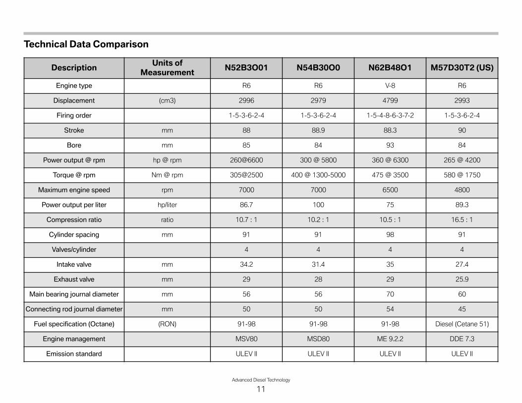
Technical Data Comparison
Description Units ofMeasurement N52B3O01 N54B30O0 N62B48O1 M57D30T2 (US)
Engine type R6 R6 V-8 R6
Displacement (cm3) 2996 2979 4799 2993
Firing order 1-5-3-6-2-4 1-5-3-6-2-4 1-5-4-8-6-3-7-2 1-5-3-6-2-4
Stroke mm 88 88.9 88.3 90
Bore mm 85 84 93 84
Power output @ rpm hp @ rpm 260@6600 300 @ 5800 360 @ 6300 265 @ 4200
Torque @ rpm Nm @ rpm 305@2500 400 @ 1300-5000 475 @ 3500 580 @ 1750
Maximum engine speed rpm 7000 7000 6500 4800
Power output per liter hp/liter 86.7 100 75 89.3
Compression ratio ratio 10.7 : 1 10.2 : 1 10.5 : 1 16.5 : 1
Cylinder spacing mm 91 91 98 91
Valves/cylinder 4 4 4 4
Intake valve mm 34.2 31.4 35 27.4
Exhaust valve mm 29 28 29 25.9
Main bearing journal diameter mm 56 56 70 60
Connecting rod journal diameter mm 50 50 54 45
Fuel specification (Octane) (RON) 91-98 91-98 91-98 Diesel (Cetane 51)
Engine management MSV80 MSD80 ME 9.2.2 DDE 7.3
Emission standard ULEV II ULEV II ULEV II ULEV II

Power Output Comparison
Diesel vs. N52
The following full load diagrams provide a comparison of the newdiesel engine to the current production gasoline engines, both 6and 8 cylinder.
Most notably, the diesel has the advantage in the torque output.The above comparison shows a comparison between the N52engine, which is a naturally aspirated 3-liter gasoline engine.
The power developed by the gasoline engine is carried over abroader RPM range, but the diesel has more output torque which isavailable at a much lower engine speed.
Diesel vs. N54
In the above graph, the N54 has a slight advantage in peak outputwith regard to horsepower. Since the N54 is a turbochargedengine, the output torque figures show the torque output at a lowerengine speed, but it is quite “flat” up to almost 5000 RPM.
In contrast, the diesel has a much higher torque output, but is onlyavailable for a short time. After about 2400 RPM, the torque dropsoff considerably.
Nmlbft
600443 268200
560413 241180
520384 215160
480354 188140
440325 161120
400295 134100
360265 10780
320236 8060
280207 5440
240177 2720
200148 00
349260
322240
295220
hpkW
1000 2000 3000 4000 5000 70006000
M57D30T2 (335d, X5 XDrive35d) N52B30O1 (X5 3. 0si)
n [1/min]TD
08-137
8
Nmlbft
600443 268200
560413 241180
520384 215160
480354 188140
440325 161120
400295 134100
360265 10780
320236 8060
280207 5440
240177 2720
200148 00
349260
322240
295220
hpkW
1000 2000 3000 4000 5000 70006000
M57D30T2 (335d, X5 XDrive35d) N54B30O0 (335i)
n [1/min]
TD08
-137
9
12Advanced Diesel Technology

Comparison to the V8 Engine
Nmlbft
600443 268200
560413 241180
520384 215160
480354 188140
440325 161120
400295 134100
360265 10780
320236 8060
280207 5440
240177 2720
200148 00
349260
322240
295220
hpkW
1000 2000 3000 4000 5000 70006000
M57D30T2 (335d, X5 XDrive35d) N62B48O1 (X5 4.8i)
n [1/min]
TD08
-138
0
The familiar N62B48O1 has impressive horsepower output but,even with 8-cylinders, it does not have the torque output of theM57 diesel engine.
Overall, these engine output graphs illustrate that the diesel hasvery specific characteristics especially with regard to torque output.
Vehicles with diesel engines are adapted to suit these torquecharacteristics with an upgraded torque converter and a rear axlegear ratio which allows the full utilization of the output curve.
In short, the new BMW diesel engine exceeds all of the currentlyavailable gasoline engines up to an engine speed of about 4000rpm.
Advanced Diesel Technology
13

14Advanced Diesel Technology
Workshop Exercise - VehicleWalkaround
1. Locate the following components on both vehicles (E70and E90), look over both vehicles and fill in requestedinformation:
� Locate the dipstick on the E70 and E90.
Why is one red and one black?
� Look at the method of oil checking between both vehicles
What is the difference between the two?
� Locate the SCR fill points on both vehicles
Where are they located?
E70:
E90:
� Locate the additional underbody paneling on the E90
� Locate SCR reservoirs (tanks) on both vehicle and note locations:
E70: Passive Tank
Active Tank
E90: Passive Tank
Active Tank
� Locate the fuel filter
� Locate the oil filter and drain plug locations
� Locate the air filters and housings
� Open the fuel filler door and remove cap, note differences
� Examine the DPF on both vehicles and note the differences
� Note the EGR system and the differences between E70 and E90
� Note the external appearance of the E70 and compare with gasolineversion:
How can you ID a diesel vehicle (without looking at the badges)?
� Note the external appearance of the E90 and compare with gasolineversion:
How can you ID a diesel vehicle (without looking at the badges)?

Advanced Diesel Technology
15
NOTESPAGE
16Advanced Diesel Technology
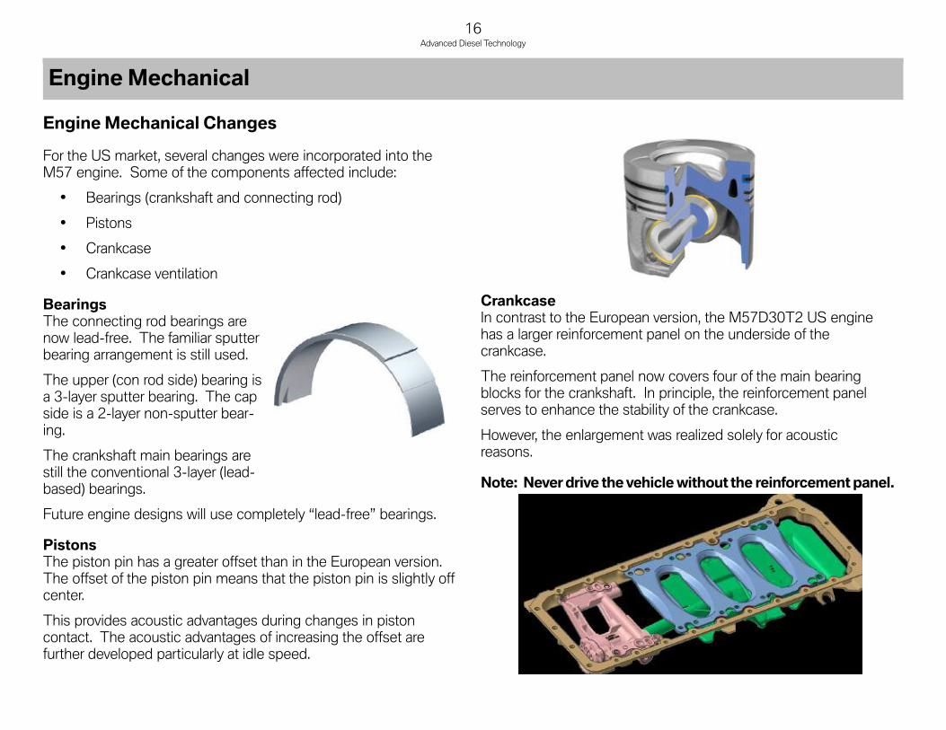
Engine Mechanical Changes
For the US market, several changes were incorporated into theM57 engine. Some of the components affected include:
• Bearings (crankshaft and connecting rod)
• Pistons
• Crankcase
• Crankcase ventilation
BearingsThe connecting rod bearings arenow lead-free. The familiar sputterbearing arrangement is still used.
The upper (con rod side) bearing isa 3-layer sputter bearing. The capside is a 2-layer non-sputter bear-ing.
The crankshaft main bearings arestill the conventional 3-layer (lead-based) bearings.
Future engine designs will use completely “lead-free” bearings.
PistonsThe piston pin has a greater offset than in the European version.The offset of the piston pin means that the piston pin is slightly offcenter.
This provides acoustic advantages during changes in pistoncontact. The acoustic advantages of increasing the offset arefurther developed particularly at idle speed.
CrankcaseIn contrast to the European version, the M57D30T2 US enginehas a larger reinforcement panel on the underside of thecrankcase.
The reinforcement panel now covers four of the main bearingblocks for the crankshaft. In principle, the reinforcement panelserves to enhance the stability of the crankcase.
However, the enlargement was realized solely for acousticreasons.
Note: Neverdrive thevehiclewithout the reinforcementpanel.
Engine Mechanical

Advanced Diesel Technology
17
Crankcase VentThe crankcase vent in the US version is heated. In addition, theoperation of the crankcase breather is OBD monitored. This isbecause a leaking system would increase unwanted emissions.
The only probable reason for a leak in the system would be that theblow-by pipe is not connected to the cylinder head cover. In orderto facilitate protection of this situation by the OBD, the heating lineis routed via a connector to the cylinder head cover (2).
Essentially, this connector serves only as a bridge so that actuationof the heating system is looped through. The plug connection isdesigned in such a way that correct contact is made only when theblow-by pipe has been connected correctly to the cylinder headcover, i.e. the contact for the heating system is not closed if theblow-by pipe is not connected to the cylinder head cover. TheOBD system recognizes this situation as a fault.
Note: If the blow-by pipe is not connected to the cylinderhead correctly, the OBDwill activate the MIL(Malfunction Indicator Lamp).
Index Explanation Index Explanation
1 Cylinder head cover 5 Filtered intake air
2 Blow-by heater connection (OBD) 6 Blow-by heater connection at blow-by pipe
3 Blow-by heater connection atwiring harness 7 Intake air to exhaust turbocharger
4 Filtered air pipe 8 Blow-by pipe
Note:
When making repairs which concern malfunctions of thecrankcase ventilation system. Or, if any repairs are made to aturbocharger which has leaked oil into the engine, be sure toremove any residual oil in the intake air system.
Failure to do so may result in an engine over-rev situationcausing irreparable engine damage. In this case, the warrantymay be affected.
18Advanced Diesel Technology
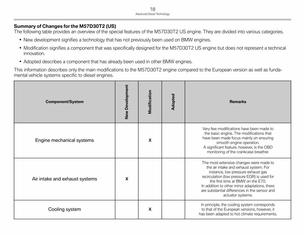
Summary of Changes for the M57D30T2 (US)The following table provides an overview of the special features of the M57D30T2 US engine. They are divided into various categories.
• New development signifies a technology that has not previously been used on BMW engines.
• Modification signifies a component that was specifically designed for the M57D30T2 US engine but does not represent a technicalinnovation.
• Adopted describes a component that has already been used in other BMW engines.
This information describes only the main modifications to the M57D30T2 engine compared to the European version as well as funda-mental vehicle systems specific to diesel engines.
Component/System
NewDevelopment
Modification
Adopted
Remarks
Engine mechanical systems X
Very few modifications have been made tothe basic engine. The modifications thathave been made focus mainly on ensuring
smooth engine operation.A significant feature, however, is the OBDmonitoring of the crankcase breather.
Air intake and exhaust systems X
The most extensive changes were made tothe air intake and exhaust system. Forinstance, low pressure exhaust gas
recirculation (low pressure EGR) is used forthe first time at BMW on the E70.
In addition to other minor adaptations, thereare substantial differences in the sensor and
actuator systems.
Cooling system XIn principle, the cooling system correspondsto that of the European versions, however, it
has been adapted to hot climate requirements.

Advanced Diesel Technology
19
Component/System
NewDevelopment
Modification
Adopted
Remarks
High pressure fuel system X
The functional principle of the fuelpreparation system does not differ from thatof the European version, however, individualcomponents have been adapted to the
different fuel specification.
Fuel supply system X
The fuel supply system is vehicle-specificand corresponds to the European version.There are, however, significant differences to
petrol engine vehicles.
Selective Catalytic Reduction System (SCR) X
The SCR system is used for the first time at BMW.Nitrogen oxide emissions are drastically reduced by the use ofa reducing agent that is injected into the exhaust system
upstream of a special SCR catalytic converter.Since the reducing agent is carried in the vehicle, a supplyfacility, made up of two reservoirs, is part of this system
Engine electrical system X
The engine is equipped with the new DDE7(digital diesel electronics) control unit that will
be used in the next generation diesel engines (N57).The preheater (glow plug) system also corresponds to the
N57 engines.
Automatic transmission X
The automatic transmission corresponds to that in the ECEvariant of the X5 xDrive35d. The gearbox itself has alreadybeen used in the US version of the X5 4.8i, however, adifferent torque converter is used for the diesel model.

20Advanced Diesel Technology
Diesel Vehicles for the USMarket
Aside from the engine itself, there are several changes which havebeen made to the diesel versions of the 335d and X5. Thesechanges are required to successfully adapt the diesel engine.
These changes are as follows:
• Transmission
• Rear differential
• Cooling system
• Climate control system (auxiliary PTC heater)
• Acoustic package
TransmissionIn view of the high torque developed by the M57D30T2 engine,the GA6HP26TU gearbox is used, which is normally fitted behind8-cylinder gasoline engines.
The transmission gear ratios have not been changed.
Twin DamperTorque ConverterThe gearbox is identical to that used in the X5 4.8i; only the torqueconverter is different.
A so-called turbine torsional damper (TTD) is used while a twindamper torque converter is used for diesel engines.
In principle, the twin damper torque converter is a turbine torsionaldamper with a further damper connected upstream. The primaryside of the first damper is connected to the converter lockupclutch while the secondary side is connected to the primary sideof the second damper. As in the turbine torsional damper, thesecondary side is fixed to the turbine wheel of the torqueconverter.
When the converter lockup clutch is open, the power flow is equalto that of the turbine torsional damper. The power is transferredfrom the turbine wheel via the second damper (but without damp-ing) to the transmission input shaft.
When the converter lockup clutch is closed, the power is transmit-ted via the first damper that consists of an annular spring.From here the power is transmitted to the second damper whichoperationally corresponds to the turbine torsional damper and alsoconsists of two annular springs.
These further improved damping properties effectively adapt thetransmission to the operational irregularities of the diesel engine.
Vehicle Specific Diesel Changes

Advanced Diesel Technology
21
Rear DifferentialIn order to optimize the torque curve of the diesel engine, thedifferential ratio has been changed in the final drive. The ratio isnow numerically lower which keep the RPM to an optimum level.The following charts show the comparisons of the transmissionand final drive ratios between the gasoline and diesel versions.
Index Explanation Index Explanation
1 Annular spring 5 Stator
2 Converter housing 6 Transmission input shaft
3 Turbine wheel 7 Annular spring assembly
4 Impeller
22Advanced Diesel Technology
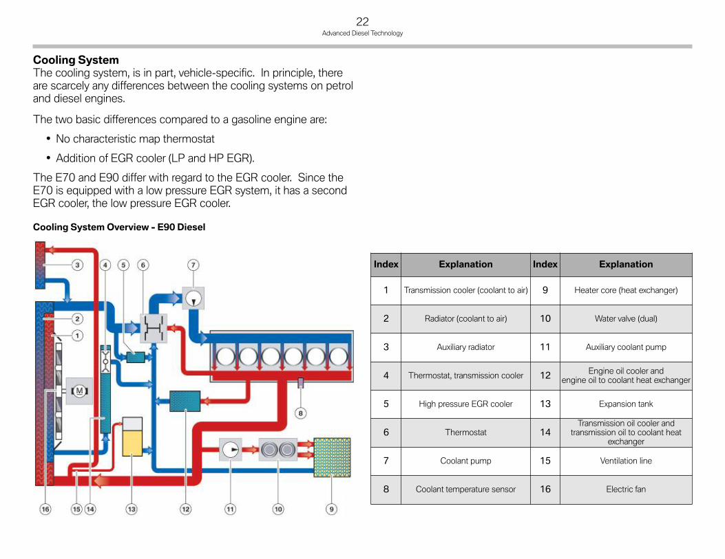
Cooling SystemThe cooling system, is in part, vehicle-specific. In principle, thereare scarcely any differences between the cooling systems on petroland diesel engines.
The two basic differences compared to a gasoline engine are:
• No characteristic map thermostat
• Addition of EGR cooler (LP and HP EGR).
The E70 and E90 differ with regard to the EGR cooler. Since theE70 is equipped with a low pressure EGR system, it has a secondEGR cooler, the low pressure EGR cooler.
Index Explanation Index Explanation
1 Transmission cooler (coolant to air) 9 Heater core (heat exchanger)
2 Radiator (coolant to air) 10 Water valve (dual)
3 Auxiliary radiator 11 Auxiliary coolant pump
4 Thermostat, transmission cooler 12 Engine oil cooler andengine oil to coolant heat exchanger
5 High pressure EGR cooler 13 Expansion tank
6 Thermostat 14Transmission oil cooler and
transmission oil to coolant heatexchanger
7 Coolant pump 15 Ventilation line
8 Coolant temperature sensor 16 Electric fan
Cooling SystemOverview - E90 Diesel

Advanced Diesel Technology
23
Cooling SystemOverview - E70 Diesel
Cooling MethodThe cylinder head varies according to the engineering used toimplement the cooling concept.
There are 3 types of cooling concepts:
• Crossflow cooling
• Longitudinal flow cooling
• Combination of the two.
In BMW diesel engines only crossflow cooling is used. With cross-flow cooling, the coolant flows from the hot exhaust side of thecylinder head to the cooler inlet side.
This offers the advantage of even heat distribution throughout thecylinder head. By contrast, with longitudinal flow cooling, thecoolant flows lengthways along the cylinder head, in other wordsfrom one end to the other.
As the coolant flows past each cylinder in succession, it becomesprogressively hotter, resulting in very uneven heat distribution.This also causes pressure losses in the coolant circulation system.
A combination of both systems cannot outweigh the disadvantagesof longitudinal flow cooling. Consequently, BMW diesel enginesexclusively use crossflow cylinder head cooling.
Index Explanation Index Explanation
1 Radiator (coolant to air) 10 Heater core (heat exchanger)
2 Transmission cooler (coolant to air) 11 Water valve (dual)
3 Electric fan 12 Auxiliary coolant pump
4 Thermostat, transmission cooler 13 Engine oil cooler andengine oil to coolant heat exchanger
5 High pressure EGR cooler 14 Expansion tank
6 Thermostat 15Transmission oil cooler and
transmission oil to coolant heatexchanger
7 Coolant pump 16 Ventilation line
8 Low pressure EGR cooler 17 Auxiliary radiator
9 Coolant temperature sensor

24Advanced Diesel Technology
Climate Control for Diesel VehiclesThe climate control system on the diesel vehicles is mostly identi-cal to those on vehicles with gasoline engines. The major additionto the system is an electric auxiliary PTC heater. Both the E70 andE90 use an auxiliary PTC heater.
Since diesel engines are more thermally efficient than gasolineengines, the warmup time is increased. This can potentially causea “comfort” related issue for the customer. So, this heater is need-ed to “boost” the output of the heater core until the coolanttemperature is sufficient to provide the necessary heating.
The PTC heater does not heat the coolant, but rather the air pass-ing through the heater core. The electric auxiliary heater is installedin the IHKA housing next to the heater core.
This is connected to the IHKA via the LIN bus and is controlledbetween 0 - 100% when heating is required (infinitely variable).The electric PTC auxiliary heater may only be operated usingexcess alternator power.
The power consumption can be limited via the DDE using powermanagement. Notification of power availability is provided by theDDE via a CAN signal on the vehicle circuit and relayed to theelectric PTC auxiliary heater by the IHKA via the LIN bus.
The output of the electric PTC auxiliary heater is 1250 W at avoltage of 13 V. The electric auxiliary heater consists of a heatinggrid and integrated actuation electronics.
The PTC heater has the following characteristics:
• Ceramic heating elements (PTC ceramic resistors)
• Access to air via metal grilles
• Actuation electronics.
Index Explanation Index Explanation
1 IHKA housing 6 Evaporator temperature sensor
2 Fresh air intake 7 Heat exchanger
3 Connection to expansion valve 8 PTC heater
4 Coolant connection to heatexchanger (heater core) 9 Temperature sensor for
heat exchanger
5 Evaporator
Auxiliary PTC heater in A/C housing - E70

Advanced Diesel Technology
25
Front PTC Pin AssignmentsThe power connection and the signal connection are separate.
Power connection:
• Terminal 30
• Terminal 31.
Front PTC signal connection:
• Plug (3-pin)
• Terminal 15
• Generator load signal (PWM)
• LIN bus.
The electric PTC auxiliary heater has diagnostic capability fordetecting faults such as:
• Missing contact
• Short circuit to ground and B+
The electronic system performs continuous self-diagnosis. Thismakes it possible to activate internal safety functions and make thediagnostic data available to the IHKA control unit via the LIN bus.
The following items have diagnostic capability:
• Presence of power supply, terminal 15 and power supplyvoltage measurement
• Power output stage fault
The following safety functions are provided with the aid ofself-diagnosis:
• PTC shut-off if the permitted operating voltage range isexceeded.
PTC Heater E90
Index Explanation Index Explanation
1 DDE 5 IHKA control module
2 Alternator 6 Instrument cluster
3 PTC heater(with integrated electronics) 7 Junction box
4 Ambient temperature
PTC Heater s schematic - E90

26Advanced Diesel Technology
Acoustic PackageOn the E90, there is additional paneling in the underbody belowthe engine. This paneling is used to further reduce any enginerelated noise which may emanate from the diesel engine.

Advanced Diesel Technology
27
NOTESPAGE
In contrast to the ECE version of the M57D30T2 engine, the USversion of the engine electrical system features followingdifferences:
• Engine control unit DDE7.3
• Preheating system with LIN-bus link and ceramic heaterplugs
• Additional OBD sensors
• Electrically operated swirl flap and EGR valve
• Additional actuators and sensors for the low pressure EGRsystem.
Engine Control Module
The new DDE7.3 engine control module is used on the USversion M57D30T2 engine. The DDE 7 version is used due tothe fact that the DDE 6 engine control module was not sufficientto accommodate the addition of the SCR system as well as addi-tional OBD functions.
DDE 7 will be used on future generations of diesel enginesincluding the N57 which will be available sometime later.
28Advanced Diesel Technology
Diesel Engine Management

Sensors and ActuatorsIn the M57D30T2 US engine, the modifications to the sensors andactuators are restricted to the air intake and exhaust system.
Several new components have been added to this system.The table below provides an overview. It shows a comparisonbetween the E70 US and E90 US and the ECE variant (EURO4).
ELElectrically actuated
EUVVacuum controlled via electric changeover valve (on/off)
EPDWVacuum controlled via electro-pneumatic pressure converter(PWM controlled)
Advanced Diesel Technology
29
Sensors EURO 4 E70 US E90 US
Outside temperature sensor X X X
Ambient pressure sensor X X X
HFM X X X
Intake air temp sensor (in HFM) X X X
Charge air temperature sensor X X X
Boost pressure sensor X X X
Exhaust pressure sensorat exhaust manifold (before DPF) X X X
Oxygen sensor X X X
Exhaust gas temperature sensor beforediesel oxidation catalyst (DOC) X X X
Exhaust gas temperature sensor beforediesel particulate filter (DPF) X X X
Exhaust backpressure sensor beforediesel particulate filter (DPF) X - -
Exhaust differential pressure sensor - X X
Temperature sensor afterLP-EGR cooler - X -
Temperature sensor afterHP-EGR cooler - X X
Exhaust gas temperature sensor beforeSCR catalyst - X X
Actuators EURO 4 E70 US E90 US
Compressor bypass valve EUV EUV EUV
Turbine control valve EPDW EPDW EPDW
Wastegate EPDW EPDW EPDW
Throttle valve EL EL EL
Swirl flaps EUV EL EL
High pressure EGR valve EPDW EL EL
Low pressure EGR valve - EPDW -
Bypass valve for HP-EGR cooler - EUV EUV
SCR metering valve EL EL
Sensors EURO 4 E70 US E90 US
NOx sensor before SCR catalyst - X X
NOx sensor after SCR catalyst - X X
Positional feedback swirl flaps - X X
Positional feedback HP-EGR valve - X X
Positional feedback LP-EGR valve - X -
Blow-by connection - X X

OBDMonitored Functions
The engine management has the additional task of monitoring allexhaust-relevant systems to ensure they are functioning correctly.This task is known as On Board Diagnosis (OBD).
The malfunction indicator lamp (MIL) is activated if the onboarddiagnosis registers a fault. The events specific to US diesel enginesthat cause the MIL to light up are described in the following.
Diesel Oxidation CatalystThe oxidation catalytic converter is monitored with regard to itsconversion ability which diminishes with aging. The conversion ofhydrocarbons (HC) during cold start is used as the indicator as heatis produced as part of the chemical reaction and it follows a definedtemperature progression after the oxidation catalytic converter.
The exhaust gas temperature sensor after the oxidation catalyticconverter measures the temperature. The DDE maps the tempera-ture progression during cold start and compares it to calculatedmodels. The result determines how effective the oxidation catalyticconverter is operating.
A reversible fault is stored if the temperature progression dropsbelow a predetermined value. If this fault is still determined aftertwo successive diesel particulate filter regeneration cycles, anirreversible fault is stored and the MIL is activated.
SCR Catalytic ConverterThe effectiveness of the SCR catalytic converter is monitored bythe two NOx sensors. The nitrogen mass is measured before andafter the SCR catalytic converter and a sum is formed over adefined period of time. The actual reduction is compared with acalculated value that is stored in the DDE.
The following conditions must be met for this purpose:
• NOx sensors plausible
• Metering active
• Ambient temperature in defined range
• Ambient pressure in defined range
• Regeneration of diesel particulate filter not active
• SCR catalytic converter temperature in defined range(is calculated by means of exhaust temperature sensor beforeSCR catalytic converter)
• Flow of exhaust gas in defined range.
Monitoring involves four measuring cycles. A reversible fault isstored if the actual value is lower than the calculated value. If thefault is determined in two successive driving cycles, an irreversiblefault is stored and the MIL is activated.
Long-term adaptation is implemented, where the metered quantityof urea-water solution is adapted, to ensure the effectiveness of theSCR catalytic converter over a long period of time. To execute thisadaptation procedure, the signal of the NOx sensor after the SCRcatalytic converter is compared with a calculated value. If variationsoccur, the metered quantity is correspondingly adapted in the shortterm.
The adaptations are evaluated and a correction factor is applied tothe metered quantity.
The operating range for the long-term adaptation is the same asthat for effectiveness monitoring.
A reversible fault is stored if the correction factor exceeds a definedthreshold. If the fault is determined in two successive drivingcycles, an irreversible fault is stored and the MIL is activated.
30Advanced Diesel Technology
Supplying Urea-water SolutionA supply of a urea-water solution is required to ensure efficientoperation of the SCR catalytic converter.
Once the SCR catalytic converter has reached a certain tempera-ture (calculated by the exhaust gas temperature sensor before theSCR catalytic converter), the metering control system attempts tobuild up pressure in the metering line.
For this purpose, the metering module must be closed and thedelivery pump actuated at a certain speed for a defined period oftime.
If the defined pressure threshold cannot be reached within a certaintime, the metering module is opened in order to vent the meteringline. This is followed by a new attempt to build up pressure.
A reversible fault is stored if a defined number of pressure build-upattempts remain unsuccessful. If the fault is determined in twosuccessive driving cycles, an irreversible fault is stored and the MILis activated.
This monitoring takes place only once per driving cycle beforemetering begins. Continuous pressure monitoring begins after thismonitoring run was successful.
A constant pressure of the urea-water solution (5 bar) is requiredfor the selective catalytic reduction process. The actual pressure ismeasured by the pressure sensor in the delivery module andcompared with a minimum and a maximum pressure threshold.
A reversible fault is stored if the limits are exceeded for a certaintime. If the fault is determined in two successive driving cycles, anirreversible fault is stored and the MIL is activated.
This monitoring run takes place while metering is active.
Level Measurement in Active ReservoirA level sensor with three contacts at different heights is used forthe active reservoir. The plausibility of the sensor is checked in theevaluator in that it checks whether the signals are logical.
For example, it is improbable that the "Full" contact is covered bythe solution while the "Empty" contact is not. In this case, theevaluator sends a plausibility error to the DDE. This takes place ata pulse duty factor of 30% of the PWM signal. A reversible fault isset. If the fault is determined in two successive driving cycles, anirreversible fault is stored and the MIL is activated.
This monitoring procedure only takes place if the temperature inthe active reservoir is above a defined value.
If the line between the evaluator and at least one contact of thelevel sensor is interrupted, the fault is signalled to the DDE by aPWM signal with 40% pulse duty factor. A reversible fault is set.
If the fault is determined in two successive driving cycles, an irre-versible fault is stored and the MIL is activated.
Suitable Urea-water SolutionThe SCR system is monitored with regard to refilling with an incor-rect medium. This monitoring function starts when refilling isdetected. Refilling detection is described in the section on theSCR system.
Effectiveness monitoring of the SCR catalytic converter is used forthe purpose of determining whether an incorrect medium has beenused. An incorrect medium is detected if the effectiveness dropsbelow a certain value within a defined period of time after refilling.
A reversible fault is set in this case. If the fault is determined in twosuccessive driving cycles, an irreversible fault is stored and the MILis activated.
In addition, the warning scenario with a remaining range of 200 mlsis started.
Advanced Diesel Technology
31
NOx SensorsA dew point must be reached for effective operation and thereforealso the monitoring of the NOx sensor. This ensures that there isno longer any water in the exhaust system that could damage theNOx sensors.
A reversible fault is set if the following monitoring functions detect afault at the NOx sensor. If the fault is determined in two successivedriving cycles, an irreversible fault is stored and the MIL is activat-ed.
• Detection signal or correction factor incorrect
• Line break or short-circuit between measuring probe and con-trol unit of NOx sensor
• Measured value outside the defined range for a certain periodof time
• Operating temperature is not reached after a defined heatingtime
• The distance from the measured value to zero is too great inoverrun mode (no nitrogen oxides expected)
• During the transition from load to overrun mode, the signal ofthe NOx sensor does not drop fast enough from 80% to 50%(only NOx sensor before SCR catalytic converter)
• If, despite a peak in the signal of the NOx sensor before theSCR catalytic converter, at least a defined change in the signalof the NOx sensor after the SCR catalytic converter is notdetermined this is interpreted as implausible.
Exhaust Gas Recirculation (EGR)During normal operation, the exhaust gas recirculation is controlledbased on the EGR ratio. During regeneration of the diesel particu-late filter, it is conventionally controlled based on the air mass.
The monitoring function also differs in this way: During normaloperation a fault is detected when the EGR ratio is above or belowdefined limits for a certain period of time.
This applies to the air mass during regeneration of the diesel par-ticulate filter. In order to monitor the high pressure EGR cooler, thetemperature after the high pressure EGR cooler is measured withthe bypass valve open and close with the engine running at idlespeed. A fault is detected if the temperature difference is below acertain value.
For the low pressure EGR cooler (only E70), the measured temper-ature after the low pressure EGR cooler is compared with a calcu-late temperature for this position. A fault is detected if the differ-ence exceeds a certain value.
Each of these faults is stored reversible. If the fault is determined intwo successive driving cycles, an irreversible fault is stored and theMIL is activated.
32Advanced Diesel Technology
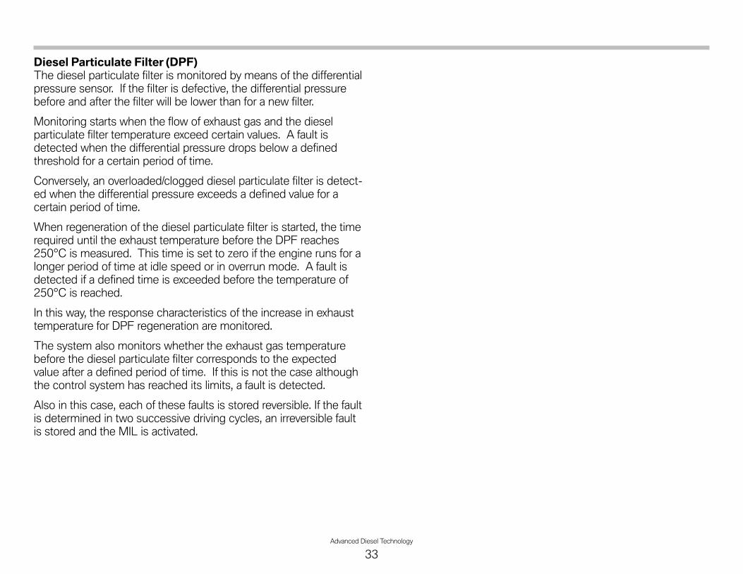
Diesel Particulate Filter (DPF)The diesel particulate filter is monitored by means of the differentialpressure sensor. If the filter is defective, the differential pressurebefore and after the filter will be lower than for a new filter.
Monitoring starts when the flow of exhaust gas and the dieselparticulate filter temperature exceed certain values. A fault isdetected when the differential pressure drops below a definedthreshold for a certain period of time.
Conversely, an overloaded/clogged diesel particulate filter is detect-ed when the differential pressure exceeds a defined value for acertain period of time.
When regeneration of the diesel particulate filter is started, the timerequired until the exhaust temperature before the DPF reaches250°C is measured. This time is set to zero if the engine runs for alonger period of time at idle speed or in overrun mode. A fault isdetected if a defined time is exceeded before the temperature of250°C is reached.
In this way, the response characteristics of the increase in exhausttemperature for DPF regeneration are monitored.
The system also monitors whether the exhaust gas temperaturebefore the diesel particulate filter corresponds to the expectedvalue after a defined period of time. If this is not the case althoughthe control system has reached its limits, a fault is detected.
Also in this case, each of these faults is stored reversible. If the faultis determined in two successive driving cycles, an irreversible faultis stored and the MIL is activated.
Advanced Diesel Technology
33

34Advanced Diesel Technology
Air Intake and Exhaust Systems
The M57D30T2 US engine exhibits thefollowing special features in the air intakeand exhaust system:
• Electric swirl flaps
• Electric exhaust gas recirculation valve(High pressure EGR valve)
• Low pressure EGR (E70 only)
• Turbo assembly adapted for lowpressure EGR. (E70 only)

Advanced Diesel Technology
35
Index Explanation Index Explanation
1 Diesel engine - M57D30T2 18 Oxidation catalyst and Diesel particle filter (DOC/DPF)
2 Intake silencer (air filter) 19 Exhaust gas temperature sensor - pre catalyst (DOC)
3 HFM 20 Oxygen sensor
4 Compressor bypass valve 21 Wastegate valve
5 Turbocharger - low pressure stage 22 Turbine control valve
6 Turbocharger - high pressure stage 23 Exhaust pressure sensor (after exhaust manifold)
7 Bypass valve for High Pressure EGR cooler 24 Swirl port actuator
8 High-pressure EGR cooler 25 Boost pressure sensor
9 Temperature sensor for high-pressure EGR 26 Exhaust differential pressure sensor
10 High-pressure EGR valve 27 NOx sensor - pre SCR catalyst
11 Throttle valve 28 Temperature sensor - post DPF
12 Charge air temperature sensor 29 Dosing (metering) module (for SCR system)
13 Intercooler 30 Mixer (for SCR system)
14 Low pressure EGR valve with position sensor 31 SCR Catalyst
15 Temperature sensor for low pressure EGR 32 NOx sensor - post SCR catalyst
16 Low pressure EGR cooler 33 DDE 7.3
17 Exhaust gas temperature sensor - post catalyst (DOC) 34 Muffler (silencer)

36Advanced Diesel Technology
Index Explanation Index Explanation
A Air intake system - E70 3 Air filter housing
B Air intake system - E90 4 HFM
1 Intake air point of entry 5 Fresh (filtered) air intake pipe
2 Unfiltered air intake 6 Blow-by tube
Air Intake Systems
The intake air ductwork differs between the E70 and E90. Both vehicles will draw air from behind the kidney grill. On the E70, the air filterhousing and silencer is located on top of the engine. On the other hand, the E90 has a filter housing on the passenger side inner fender.

Advanced Diesel Technology
37
Index Explanation Index Explanation
1 Control rod for swirl flaps 5 Swirl ports
2 Throttle plate mounting 6 Tangential ports
3 Intake manifold 7 Swirl flaps
4 Electric motor (for swirl flaps)
Swirl FlapsThe US version of the M57 engine utilizes the previously known swirl flaps which are located in the intake manifold. The primary differ-ence is that the swirl flaps are now controlled electrically, rather than with vacuum. This method of actuation also provides a means ofposition feedback with the DDE system to comply with OBD requirements. An additional benefit of this method of control is a moreprecise positioning of the swirl flaps as needed. The flaps are map controlled using engine speed, engine load and coolant temperature.

38Advanced Diesel Technology
Exhaust System
The exhaust systems for both the E90 and E70 have been adaptedfor the US market. There are special provisions for the SCR systemas well as for the US specific OBD monitoring of the DOC.
Each system is unique to the vehicle with different muffler andtailpipe features.
EGR SystemFor more information on EGR systems, refer to the section on“Emission Controls”.
Index Explanation Index Explanation
A Exhaust system E70 6 SCR catalyst
B Exhaust system E90 7 NOx sensor after SCR catalyst
1Oxygen sensor
Exhaust gas temperature sensorbefore DOC (concealed)
8 Rear silencer (muffler)
2 Exhaust gas temperature sensorafter DOC 9 Exhaust gas temperature sensor
after DPF
3 Differential pressure sensor 10 Metering module
4 NOx sensor before SCR catalyst 11 Diesel particulate filter (DPF)
5 Mixer

Advanced Diesel Technology
39
NOTESPAGE

40Advanced Diesel Technology
Workshop Exercise - Exhaust System Components
1. Complete exercise by filling in the “function/purpose” of the exhaust system components. Then, locate and identify theexhaust system components on the vehicle:
Index Explanation Function/Purpose
A Exhaust system E70 E70
B Exhaust system E90 E90
1Oxygen sensor
Exhaust gas temperature sensor beforeDOC (concealed)
2 Exhaust gas temperature sensor afterDOC
3 Differential pressure sensor
4 NOx sensor before SCR catalyst
5 Mixer
6 SCR catalyst
7 NOx sensor after SCR catalyst
8 Rear silencer (muffler)
9 Exhaust gas temperature sensor afterDPF
10 Metering module
11 Diesel particulate filter (DPF)

Advanced Diesel Technology
41
Workshop Exercise - Exhaust System Components
Using the diagnostic equipment, access the “Service Functions” menu and go to DPF. (Do not start vehicle at this time)
What are the two selections in the DPF menu?
According to the test module, what is the replacement interval of the DPF?
When should the “DPF Regeneration” test module be carried out?
How is the “DPF Regeneration” test module carried out? (i.e. Can it be completed in the shop?)
Go to “Status Requests” under the DPF section and highlight all values. Read out with the engine running.Fill in chart below with the values:
Status request Value Status request Value
Differential pressure sensor Consumption per 100km
Regeneration enabled Distance remaining on DPF
Regeneration released Distance traveled since regeneration
42Advanced Diesel Technology
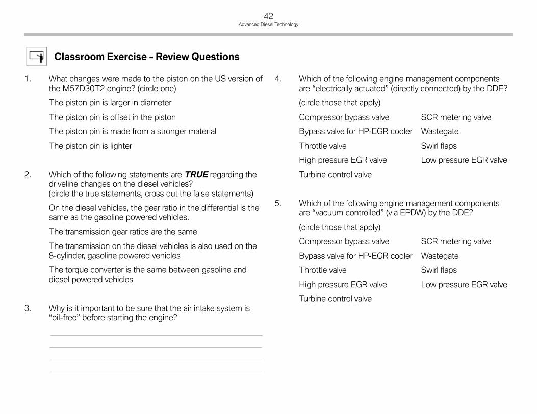
1. What changes were made to the piston on the US version ofthe M57D30T2 engine? (circle one)
The piston pin is larger in diameter
The piston pin is offset in the piston
The piston pin is made from a stronger material
The piston pin is lighter
2. Which of the following statements are TRUE regarding thedriveline changes on the diesel vehicles?(circle the true statements, cross out the false statements)
On the diesel vehicles, the gear ratio in the differential is thesame as the gasoline powered vehicles.
The transmission gear ratios are the same
The transmission on the diesel vehicles is also used on the8-cylinder, gasoline powered vehicles
The torque converter is the same between gasoline anddiesel powered vehicles
3. Why is it important to be sure that the air intake system is“oil-free” before starting the engine?
4. Which of the following engine management componentsare “electrically actuated” (directly connected) by the DDE?
(circle those that apply)
Compressor bypass valve SCR metering valve
Bypass valve for HP-EGR cooler Wastegate
Throttle valve Swirl flaps
High pressure EGR valve Low pressure EGR valve
Turbine control valve
5. Which of the following engine management componentsare “vacuum controlled” (via EPDW) by the DDE?
(circle those that apply)
Compressor bypass valve SCR metering valve
Bypass valve for HP-EGR cooler Wastegate
Throttle valve Swirl flaps
High pressure EGR valve Low pressure EGR valve
Turbine control valve
Classroom Exercise - Review Questions

Advanced Diesel Technology
43
NOTESPAGE
44Advanced Diesel Technology
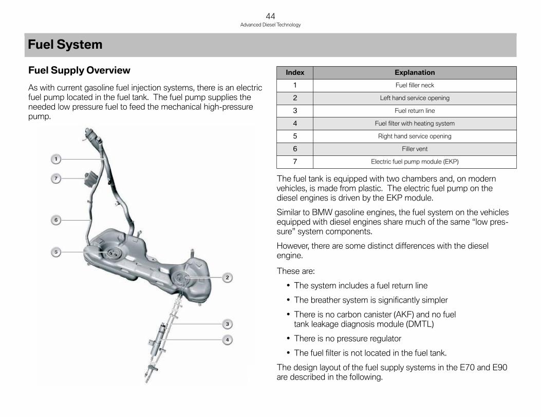
Fuel Supply Overview
As with current gasoline fuel injection systems, there is an electricfuel pump located in the fuel tank. The fuel pump supplies theneeded low pressure fuel to feed the mechanical high-pressurepump.
The fuel tank is equipped with two chambers and, on modernvehicles, is made from plastic. The electric fuel pump on thediesel engines is driven by the EKP module.
Similar to BMW gasoline engines, the fuel system on the vehiclesequipped with diesel engines share much of the same “low pres-sure” system components.
However, there are some distinct differences with the dieselengine.
These are:
• The system includes a fuel return line
• The breather system is significantly simpler
• There is no carbon canister (AKF) and no fueltank leakage diagnosis module (DMTL)
• There is no pressure regulator
• The fuel filter is not located in the fuel tank.
The design layout of the fuel supply systems in the E70 and E90are described in the following.
Index Explanation
1 Fuel filler neck
2 Left hand service opening
3 Fuel return line
4 Fuel filter with heating system
5 Right hand service opening
6 Filler vent
7 Electric fuel pump module (EKP)
Fuel System
Advanced Diesel Technology
45
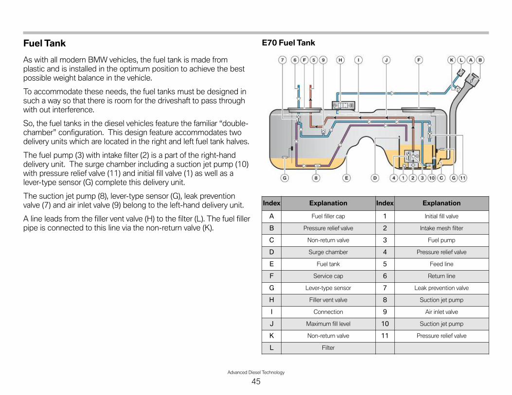
Fuel Tank
As with all modern BMW vehicles, the fuel tank is made fromplastic and is installed in the optimum position to achieve the bestpossible weight balance in the vehicle.
To accommodate these needs, the fuel tanks must be designed insuch a way so that there is room for the driveshaft to pass throughwith out interference.
So, the fuel tanks in the diesel vehicles feature the familiar “double-chamber” configuration. This design feature accommodates twodelivery units which are located in the right and left fuel tank halves.
The fuel pump (3) with intake filter (2) is a part of the right-handdelivery unit. The surge chamber including a suction jet pump (10)with pressure relief valve (11) and initial fill valve (1) as well as alever-type sensor (G) complete this delivery unit.
The suction jet pump (8), lever-type sensor (G), leak preventionvalve (7) and air inlet valve (9) belong to the left-hand delivery unit.
A line leads from the filler vent valve (H) to the filter (L). The fuel fillerpipe is connected to this line via the non-return valve (K).
E70 Fuel Tank
Index Explanation Index Explanation
A Fuel filler cap 1 Initial fill valve
B Pressure relief valve 2 Intake mesh filter
C Non-return valve 3 Fuel pump
D Surge chamber 4 Pressure relief valve
E Fuel tank 5 Feed line
F Service cap 6 Return line
G Lever-type sensor 7 Leak prevention valve
H Filler vent valve 8 Suction jet pump
I Connection 9 Air inlet valve
J Maximum fill level 10 Suction jet pump
K Non-return valve 11 Pressure relief valve
L Filter

46Advanced Diesel Technology
Fuel Tank FunctionsA pressure relief valve (B) is integrated in the fuel filler cap (A) toprotect the fuel tank (E) from excess pressure. A non-return flap (C)is located at the end of the fuel filler neck.
The non-return flap prevents the fuel from sloshing back into thefuel filler neck. The components in the fuel tank can be reachedvia the two service caps (F). The fuel fill level can be determined viathe two lever-type sensors (G). The surge chamber (D) ensures thatthe fuel pump always has enough fuel available for delivery.
Index Explanation Index Explanation
A Fuel filler cap 1 Initial fill valve
B Pressure relief valve 2 Intake mesh filter
C Non-return valve 3 Fuel pump
D Surge chamber 4 Pressure relief valve
E Fuel tank 5 Feed line
F Service cap 6 Return line
G Lever-type sensor 7 Leak prevention valve
H Filler vent valve 8 Suction jet pump
I Connection 9 Air inlet valve (check valve)
J Maximum fill level 10 Suction jet pump
L Filter 11 Pressure relief valve
Index Explanation Index Explanation
A Fuel filler cap E Fuel tank
B Pressure relief valve F Service cap
C Non-return valve G Lever-type sensors
D Surge chamber
E90 Fuel Tank

Advanced Diesel Technology
47
Fuel Delivery from Fuel TankIn the event of the surge chamber being completely empty, theinitial filling valve (1) ensures that fuel enters the surge chamberwhile refuelling.
The fuel reaches the fuel pump (3) via the intake filter (2), thencontinues through the delivery line (5) to the fuel filter. The fuelpump is located in the surge chamber. A pressure relief valve (4) isintegrated in the fuel pump to prevent pressure in the delivery linefrom rising too high.
As the engine switches off, the delivery line is depressurized butcannot run dry because, provided the system is not leaking, no airis able to enter it. In addition, after the fuel pump has switched off,the fuel pressure/temperature sensor is checked for plausibility.
Fuel that is required for lubrication and the function of high pres-sure generation flows back into the fuel tank via the return line (7).The fuel coming from the return line is divided into two lines down-stream of the leak prevention valve (7). The non-return valveprevents the fuel tank from draining in the event of damage to lineson the engine or underbody. It also prevents the return line fromrunning dry while the engine is off.
One of the lines guides the fuel into the surge chamber via a suc-tion jet pump (10). The suction jet pump transports the fuel fromthe fuel tank into the surge chamber. If the fuel delivery pressure inthe return line increases too much, the pressure relief valve (11)opens and allows the fuel to flow directly into the surge chamber.
An air inlet valve is used in the E70. The air inlet valve (9) ensuresthat air can enter the line when the engine is off, preventing fuelfrom flowing back from the right-hand half of the fuel tank to theleft.
Instead of the air inlet valve (9) a non-return valve is used on theE90. The non-return valve ensures that, while the engine is off,fuel from the right-hand half of the fuel tank cannot flow back intothe left-hand half. The return system remains completely filled withfuel.
A further line branches off into the left-hand half of the fuel tankafter the non-return valve (7) and transports the fuel into the surgechamber via the suction jet pump (8).
Index Explanation Index Explanation
1 Initial fill valve 7 Leak prevention valve
2 Intake mesh filter 8 Suction jet pump
3 Fuel pump 9 Air inlet valve
4 Pressure relief valve 10 Suction jet pump
5 Feed line 11 Pressure relief valve
6 Return line
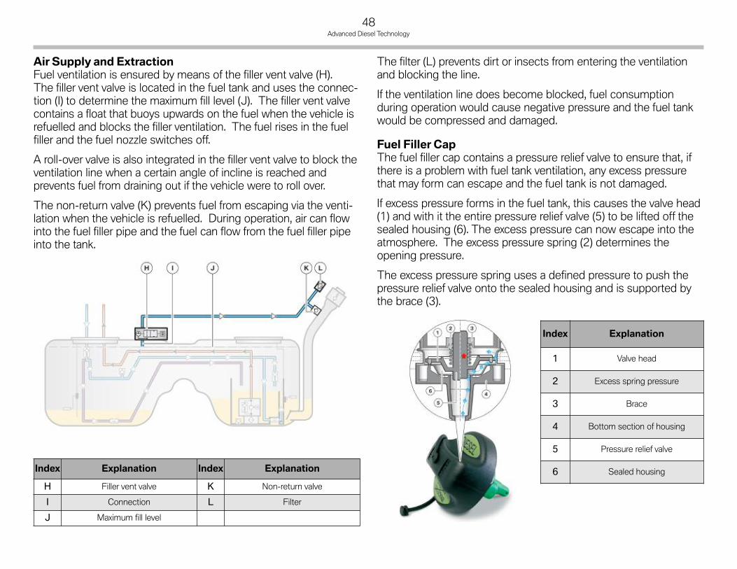
48Advanced Diesel Technology
Air Supply and ExtractionFuel ventilation is ensured by means of the filler vent valve (H).The filler vent valve is located in the fuel tank and uses the connec-tion (I) to determine the maximum fill level (J). The filler vent valvecontains a float that buoys upwards on the fuel when the vehicle isrefuelled and blocks the filler ventilation. The fuel rises in the fuelfiller and the fuel nozzle switches off.
A roll-over valve is also integrated in the filler vent valve to block theventilation line when a certain angle of incline is reached andprevents fuel from draining out if the vehicle were to roll over.
The non-return valve (K) prevents fuel from escaping via the venti-lation when the vehicle is refuelled. During operation, air can flowinto the fuel filler pipe and the fuel can flow from the fuel filler pipeinto the tank.
The filter (L) prevents dirt or insects from entering the ventilationand blocking the line.
If the ventilation line does become blocked, fuel consumptionduring operation would cause negative pressure and the fuel tankwould be compressed and damaged.
Fuel Filler CapThe fuel filler cap contains a pressure relief valve to ensure that, ifthere is a problem with fuel tank ventilation, any excess pressurethat may form can escape and the fuel tank is not damaged.
If excess pressure forms in the fuel tank, this causes the valve head(1) and with it the entire pressure relief valve (5) to be lifted off thesealed housing (6). The excess pressure can now escape into theatmosphere. The excess pressure spring (2) determines theopening pressure.
The excess pressure spring uses a defined pressure to push thepressure relief valve onto the sealed housing and is supported bythe brace (3).
Index Explanation Index Explanation
H Filler vent valve K Non-return valve
I Connection L Filter
J Maximum fill level
Index Explanation
1 Valve head
2 Excess spring pressure
3 Brace
4 Bottom section of housing
5 Pressure relief valve
6 Sealed housing
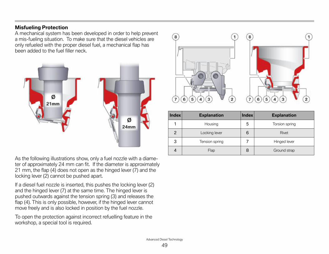
Advanced Diesel Technology
49
Misfueling ProtectionA mechanical system has been developed in order to help preventa mis-fueling situation. To make sure that the diesel vehicles areonly refueled with the proper diesel fuel, a mechanical flap hasbeen added to the fuel filler neck.
As the following illustrations show, only a fuel nozzle with a diame-ter of approximately 24 mm can fit. If the diameter is approximately21 mm, the flap (4) does not open as the hinged lever (7) and thelocking lever (2) cannot be pushed apart.
If a diesel fuel nozzle is inserted, this pushes the locking lever (2)and the hinged lever (7) at the same time. The hinged lever ispushed outwards against the tension spring (3) and releases theflap (4). This is only possible, however, if the hinged lever cannotmove freely and is also locked in position by the fuel nozzle.
To open the protection against incorrect refuelling feature in theworkshop, a special tool is required.
Index Explanation Index Explanation
1 Housing 5 Torsion spring
2 Locking lever 6 Rivet
3 Tension spring 7 Hinged lever
4 Flap 8 Ground strap

50Advanced Diesel Technology
Fuel Pump
Today's diesel vehicles are fitted with electric fuel pumps to deliverthe needed fuel to the high pressure pump. The electric fuel pumpis designed to deliver a sufficient amount of fuel to lubricate andcool the injectors and the high-pressure pump and to satisfy themaximum fuel consumption of the engine.
It has to deliver the fuel at a defined pressure. That means thatwhen the engine is idling or running at medium power, the fuelpump delivers several times more than the amount of fuel required.The fuel pump delivers approximately three or four times thevolume of maximum possible fuel consumption.
The electric fuel pump is located in the fuel tank. There it is wellprotected against corrosion and the pump noise is adequatelysoundproofed.
The fuel pump on BMW diesel engines may either be a gearpump, a roller-cell pump or a screw-spindle pump. The followingfuel pumps are used on USA vehicles:
• E70 - Screw spindle pump
• E90 - Gear pump (rotor type)
The operating principle of each of these types of pump isdescribed below. The pump itself is driven by the drive shaft (2) ofthe electric motor (3). The electric motor is controlled by theelectrical connection (6) and sliding contacts (7).
Passing first through the intake filter and then the remainder of theintake section (9), the fuel enters the impeller (1). The fuel ispumped through pressure chamber (8) on the electric motor, pastthe pressure connection (5) and onwards to the fuel filter andengine.
If the fuel delivery pressure increases to an impermissible value, thepressure relief valve (4) opens and allows the fuel to flow into thesurge chamber.
Index Explanation Index Explanation
1 Impeller 6 Electrical connection
2 Driveshaft 7 Sliding contacts
3 Electric motor 8 Pressure chamber
4 Pressure relief valve 9 Intake section
5 Pressure connection

Advanced Diesel Technology
51
Fuel Pump - E90On the E90, the fuel pump is a gear type pump. The gear pump iscomprised of an outer rotor (1) with teeth on the inside, and aninner rotor (4) with teeth on the outside. The inner rotor is drivenby the drive shaft (5) of the electric motor. The outer rotor is pro-pelled by the teeth of the inner rotor and thus turns inside thepump housing.
The inner rotor has one tooth fewer than the outer rotor, whichmeans that, with each revolution, fuel is carried into the next toothgap of the outer rotor.
During the rotary motion, the spaces on the intake side enlarge,while those on the pressure side become proportionately smaller.The fuel is fed into the rotor pump through two grooves in thehousing, one on the intake side and one on the pressure side.Together with the tooth gaps, these grooves form the intakesection (6) and pressure section (3).
Screw-spindle Pump - E70With the screw-spindle pump, two screw spindles intermesh insuch a way that the flanks form a seal with each other and thehousing. In the displacement chambers between the housing andthe spindles, the fuel is pushed towards the pressure side withpractically no pulsation.
In this way, the screw spindles pump fuel away from the fuel tank(5). The fuel is then fed to the engine (3) through the pumphousing and the fuel delivery line.
Index Explanation
1 Outer rotor
2 Fuel delivery to engine
3 Pressure section
4 Inner rotor
5 Driveshaft
6 Intake section
7 Fuel from tank
Index Explanation
1 Driveshaft screw spindle
2 Gearwheel
3 Fuel delivery to the engine
4 Screw spindle
5 Fuel from tank

52Advanced Diesel Technology
Low Pressure Fuel System - E90The low pressure fuel systems differ between the E70 and E90.The E90 is a “speed regulated” system which means that the fuelpump speed is regulated by the EKP module based on requestfrom the DDE.
The fuel pump will be activated with the “ignition on” signal. If theengine is not started, the fuel pump will be switched off after adefined time period. When the engine is switched off, the fuelpump is switched off as well.
Fuel Temperature SensorThe fuel temperature sensor islocated in the fuel feed line justbefore the high pressure pump.
The sensor consists of a tem-perature dependent resistorwith which works on the NTCprinciple.
The fuel temperature sensorregisters the fuel temperaturejust before the high pressurepump. The fuel temperature sen-sor is installed on the low pres-sure side of the fuelsystem.
The density of the fuel changes as temperature changes. The DDErequires the fuel temperature for the purpose of precisely calculat-ing the start of injection and injection quantity.
The fuel temperature sensor consists of a temperature-dependentmeasuring resistor made from semiconductor material that is inte-grated in a housing. The measuring resistor has a negativetemperature coefficient (NTC).
The digital diesel electronics compares the measured voltage witha characteristic curve that assigns a corresponding temperature toeach voltage value.
The various sensors and actuators are required for ensuringeffective operation of the fuel system and engine. Apart fromensuring compliance with legal requirements, these componentsare also responsible for providing outstanding engine performanceand the associated acoustics.
Fuel temperature sensor - E90

Advanced Diesel Technology
53
Fuel Filter Heating - E90On the E90, the fuel filter heater is not controlled directly by theDDE. A pressure switch and a temperature sensor are located inthe fuel filter housing.
The fuel heater only works with the ignition switched on and whenboth of the following conditions are fulfilled:
• Temperature drops below a defined value
• A defined fuel delivery pressure is exceeded due to cold,viscous fuel.
If the filter is clogged, a corresponding signal is sent via a diagnosisline to the DDE. This is the case when, despite a sufficiently hightemperature, the fuel pressure upstream of the filter does not drop.
The conditions for fuel filter heater operation are as follows:
• The fuel heater is is switched ON when - the fuel pressure isgreater than 6 bar AND the fuel temperature is less than 2°C.
• The fuel heater is switched off when - the fuel pressure is lessthan 5.5 bar for a duration of greater than 5 minutes OR
• the fuel temperature is greater than 12°C OR
• during the starting process if the electronics in the fuel filterdetect a battery voltage of less than 7.5 V for longer than 0.2seconds.
The fuel heater is not activated by the DDE control module.However, the fuel heater reports a detected filter blockage via thesignal DIAG_DKH to the DDE control module. The DDE controlmodule then stores the fault.

54Advanced Diesel Technology
Low Pressure Fuel System - E70The low pressure fuel system on the E70 is a “pressure regulated”system which uses the signal from the fuel pressure sensor locatedin the low pressure fuel line.
The fuel pump operates with "ignition ON". If the engine is notstarted, the fuel is switched off at a specific pressure. When theengine is running, the fuel pump is regulated on-demand by theEKP module in response to a load signal from the DDE in order toensure a uniform fuel pressure at the inlet to the high-pressurepump.
The functions of the low pressure fuel system are integrated intothe DDE control module. The DDE uses the pressure informationfrom the combined fuel pressure-temperature sensor to determinethe current actual pressure in the low pressure system.
In order to maintain the approximate delivery pressure of 4.8 to 5.0bar, the DDE uses a number of input variables. The input variablesrelevant to determining the adjusting value are:
• Actual pressure in the pre-supply system
• Engine speed
• Injection volume
The adjusting value is sent from the DDE to the EKP module in theform of a CAN message.
Fuel Pressure-temperature SensorThe fuel pressure-temperature sensor consists of two independentsensors combined in one housing.
The fuel temperature sensor is required to precisely calculate thestart of injection and injection quantity. The fuel pressure sensorregisters the fuel pressure upstream of the high pressure pump.This fuel pressure is required for the purpose of controlling the fuelpump in the fuel tank.
The fuel pump is also switched off when the engine is turned offand the fuel feed is depressurized. After the fuel pump has beenshut down, the digital diesel electronics checks and evaluates theplausibility of the fuel pressure sensor. If a fault is detected, thecorresponding fault code is stored in the fault code memory of thedigital diesel electronics.
The integrated fuel temperature sensor is identical to the fueltemperature sensor used in the E90. The fuel pressure sensor isalso integrated in the housing. Both the fuel pressure sensor andthe fuel temperature sensor features two separate connections in acommon connector housing that has four pins.
The fuel pressure sensor consists of resistors mounted on adiaphragm. The one side of the diaphragm has contact with thefuel so that the fuel pressure acts on the diaphragm.
The greater the pressure, the more the diaphragm is deflected.The resistors on the diaphragm change their resistance inresponse to the mechanical stress. A bridge circuit and electronicsignal processing circuitry in the sensor amplify the bridge voltage,compensate for temperature influences and linearize the pressurecharacteristic curve.
The output voltage for the digital diesel electronics is in the rangebetween 0 and 5 volts. As for the temperature sensor, a character-istic curve is stored in the digital diesel electronics that assigns acorresponding pressure to each voltage value.

Advanced Diesel Technology
55
Fuel Filter Heating - E70The fuel filter heating operation is somewhat different in the E70.The E70 has a pressure-controlled fuel supply system. In this sys-tem, the fuel filter heater is actuated by the DDE. The DDE com-municates with the filter heater via the signal S_KSH.
A combined fuel pressure and temperature sensor upstream of thehigh pressure pump is used. If required, the fuel filter is heatedwith an electrical heating element. The DDE switches the fuel filterheating on under the following conditions:
• Temperature drops below a defined value
• The required fuel pressure is not reached despite increasedpower intake of the electric fuel pump.
The DDE recognizes a clogged filter when the target pressureupstream of the high pressure pump is not reached despite asufficiently high fuel temperature and high current consumption ofthe electric fuel pump.
The electrical power output of the fuel pump is higher than thestored adaptation value ”electric fuel pump” plus an offset for morethan 3 seconds. The offset is determined from a characteristic mapand depends on the engine speed and fuel injection rate.
The fuel filter heating is switched off again under the following con-ditions:
• Activation time > 5 min or
• Fuel temperature > 8°C or
• Battery voltage is less than 9 volts for more than 30 seconds

56Advanced Diesel Technology
High Pressure Fuel System
The high pressure fuel system is mostly identical in design andfunction as compared to the European version. However, somecomponents have been adapted to the different fuel specification.
These components are:
• High-pressure pump
• Fuel rail
• Fuel injectors.
These adaptations are restricted to different coatings and materialson the inside.
Index Explanation Index Explanation
A Fuel feed (low pressure) 6 Return line
B Fuel return 7 Feed line
C Fuel high pressure 8 Fuel temperature (or temp/pressure)
1 Fuel rail pressure sensor 9 High pressure line
2 High pressure line 10 Fuel rail
3 Leakage line 11 Restrictor
4 Piezo injector 12 High pressure pump
5 Fuel rail pressure control valve 13 Volume control valve
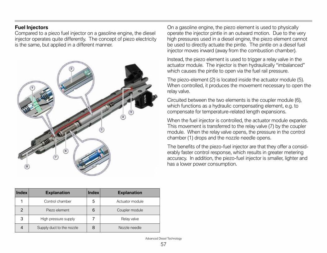
Advanced Diesel Technology
57
Fuel InjectorsCompared to a piezo fuel injector on a gasoline engine, the dieselinjector operates quite differently. The concept of piezo electricityis the same, but applied in a different manner.
On a gasoline engine, the piezo element is used to physicallyoperate the injector pintle in an outward motion. Due to the veryhigh pressures used in a diesel engine, the piezo element cannotbe used to directly actuate the pintle. The pintle on a diesel fuelinjector moves inward (away from the combustion chamber).
Instead, the piezo element is used to trigger a relay valve in theactuator module. The injector is then hydraulically “imbalanced”which causes the pintle to open via the fuel rail pressure.
The piezo-element (2) is located inside the actuator module (5).When controlled, it produces the movement necessary to open therelay valve.
Circuited between the two elements is the coupler module (6),which functions as a hydraulic compensating element, e.g. tocompensate for temperature-related length expansions.
When the fuel injector is controlled, the actuator module expands.This movement is transferred to the relay valve (7) by the couplermodule. When the relay valve opens, the pressure in the controlchamber (1) drops and the nozzle needle opens.
The benefits of the piezo-fuel injector are that they offer a consid-erably faster control response, which results in greater meteringaccuracy. In addition, the piezo-fuel injector is smaller, lighter andhas a lower power consumption.
Index Explanation Index Explanation
1 Control chamber 5 Actuator module
2 Piezo element 6 Coupler module
3 High pressure supply 7 Relay valve
4 Supply duct to the nozzle 8 Nozzle needle
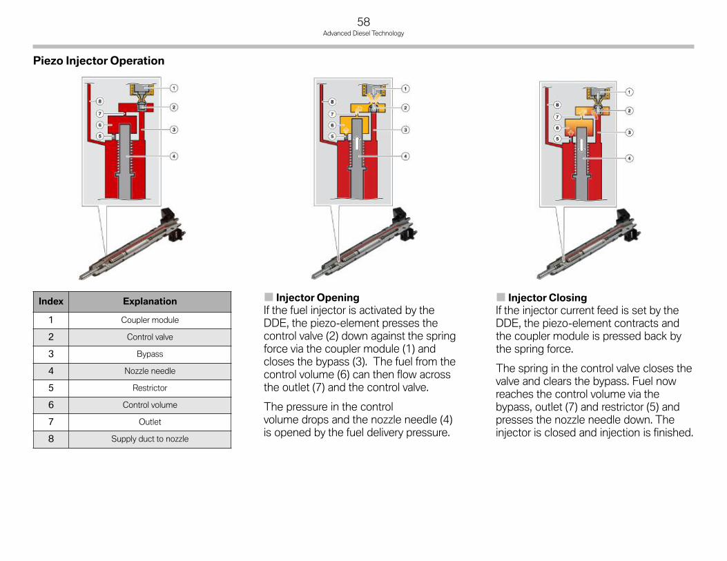
58Advanced Diesel Technology
Index Explanation
1 Coupler module
2 Control valve
3 Bypass
4 Nozzle needle
5 Restrictor
6 Control volume
7 Outlet
8 Supply duct to nozzle
Injector ClosingIf the injector current feed is set by theDDE, the piezo-element contracts andthe coupler module is pressed back bythe spring force.
The spring in the control valve closes thevalve and clears the bypass. Fuel nowreaches the control volume via thebypass, outlet (7) and restrictor (5) andpresses the nozzle needle down. Theinjector is closed and injection is finished.
Injector OpeningIf the fuel injector is activated by theDDE, the piezo-element presses thecontrol valve (2) down against the springforce via the coupler module (1) andcloses the bypass (3). The fuel from thecontrol volume (6) can then flow acrossthe outlet (7) and the control valve.
The pressure in the controlvolume drops and the nozzle needle (4)is opened by the fuel delivery pressure.
Piezo Injector Operation

Advanced Diesel Technology
59
CouplerModuleThe hydraulic coupler is surrounded by diesel fuel at a pressure ofapproximately 10 bar. The piezo-element acts on the upperplunger (1).
Lower plunger (6) rests on control valve (9). The force of spring (7)and of spring (8) is set in such a way that, when closed, the piezoelement and control valve (9) are connected free of play via thecoupler module.
The upper plunger (1) presses against coupler chamber (5) whenthe piezo-element is activated.
The force of the piezo-element is increased since plunger (1) has alarger diameter than plunger (6). Plunger (6) opens the controlvalve (9). When the coupler chamber is pressurized during activa-tion, a small leakage quantity escapes via the clearance in theplunger guide into fuel return (2).
After injection or after the piezo-element has been switched off, thesprings (7 and 8) balance out the play created by the leakage quan-tity and fuel is again drawn via the clearance in the piston guideinto the coupler chamber. This balancing out process takes placeso fast that the coupler chamber is completely filled again by thenext injection cycle.
A return pressure of approximately 10 bar is required for thispurpose, which is achieved by the restrictor in the fuel return of thefuel injectors. The control valve is not operated and no fuel isinjected when no pressure is applied in the fuel feed.
Leakage OilThe piezo injectors require a certain amount of backpressure in theleakage circuit in order to operate properly. So, the leakage circuiton the 3rd generation common rail differs from the earlier versions.
In past versions (such as 1st and 2nd generation common rail), theleakage oil circuit drained into the fuel return line.
However, since the piezo injectors operate differently than theearlier solenoid valve injectors, the leakage circuit has beenredesigned.
A certain amount of leakage oil occurs in the diesel fuel injectorsdue to the design of the system. The reason for this is that therelay valve in the piezo-fuel injector needs a certain back pressureto work correctly. The relay valve requires about 10 bar to be pres-ent in the leakage circuit to prevent injector malfunctions.
In order to maintain this pressure, a restrictor (11) has beeninstalled between the injector(s) and the low pressure feed to theHP pump.
Index Explanation
A Fuel feed
B High pressure fuel
1 Plunger
2 Fuel return
3 Spring
4 Coupler
5 Coupler chamber
6 Plunger
7 Spring
8 Spring
9 Control valve

60Advanced Diesel Technology
RestrictorThe restrictor has a .2 mm orifice which increases the pressure inthe fuel return of the fuel injectors. The operating pressure in theleakage oil circuit is about 10 bar.
The fuel flowing from the piezo-fuel injectors via the fuel returnconnection (1) initially passes through a filter (2), through restrictor(3) and then through a further filter (4) to connection (5) back intothe fuel feed to the high pressure pump.
There is a filter (2 and 4) on either side of restrictor (3) as therestrictor has no specific direction of flow. The filters ensure thatthe actual restrictor (3) does not become clogged.
Index Explanation Index Explanation
A Fuel feed 5 High pressure pump
B Fuel high pressure 6 Rail pressure control valve
C Fuel return 7 Fuel rail
1 Fuel tank 8 Fuel pressure sensor
2 Fuel filter and filter heating 9 Piezo fuel injector
3 Fuel temp (and pressure) sensor 10 DDE
4 Volume control valve 11 Fuel restrictor
Index Explanation
1 Connection from injector leakageline
2 Filter
3 Restrictor (.2mm)
4 Filter
5 Connection to low pressure line
Leakage oilcircuit - M57
3rd generationcommon rail

Advanced Diesel Technology
61
Fuel Injector Volume AdjustmentPiezo-fuel injectors not only bear the hydraulic tolerances but alsoinformation concerning the stroke characteristics of the injector.This is a separate classification for the injector voltage calibration.
This information is necessary due to the individual voltage require-ment of each fuel injector. The fuel injector is assigned to a voltagerequirement class. This replaces the seventh digit of the numericalcombination on the injector for hydraulic adjustment.
A piezo-fuel injector therefore has only six characters for thehydraulic adjustment (due to a more precise manufacture of thepiezo-fuel injectors) and a seventh character for the injector voltageadjustment.
Volume AdjustmentIf the digital diesel electronics detects engine speed fluctuations,the actuation period of the fuel injectors is corrected based onthese engine speed fluctuations. The volume adjustment adaptsthe injected volume of all cylinders with respect to each other.
Zero Volume AdaptationThe zero volume adaptation is a continual learning process.This learning process is required to enable precise pre-injection foreach individual fuel injector. Accurate metering of the very lowpre-injection volume is necessary for the fulfilment of exhaustemission regulations.
Zero volume adaptation must be carried out on a continual basisdue to the volume drift of the fuel injectors.
At each cylinder, a small amount of fuel is injected during overrunmode. This volume continues to increase until a slight increase inengine speed is detected by the digital diesel electronics.
The digital diesel electronic is thus able to detect when the respec-tive cylinder begins to work. The volume of fuel injected duringzero volume adaptation is used by the digital diesel electronics as avalue for the characteristic map of pre-injection.
Zero volume adaptation takes place alternately from one cylinder tothe next during the overrun phase at engine speeds from 1500 to2500 rpm and with the engine at operating temperature.
Zero volume adaptation has no influence on fuel consumption asonly very small quantity of fuel (about 1mm3) is injected at onecylinder at a time.
Index Explanation
1 7 Character code for adjustment
2 Voltage adjustment

62Advanced Diesel Technology
MeanVolume AdaptationThe mean volume (quantity) adaptation is a learning process inwhich the air/fuel ratio (lambda value) is corrected by the adjust-ment of the air mass or exhaust gas recirculation. Unlike the otherprocesses, this process affects all fuel injectors equally rather thanthe individual fuel injector.
An injection volume averaged across all cylinders is calculated fromthe lambda value measured by the oxygen sensor and the air massmeasured by the hot-film air mass meter. This value is comparedwith the injection volume specified by the digital diesel electronics.
If a discrepancy is detected, the air mass is adjusted to match theactual injection volume by an adjustment of the exhaust gasrecirculating valve. The correct lambda value is set in turn.
The mean volume adaptation is not an "instantaneous" regulationbut an adaptive learning process. The injection volume error istaught into an adaptive characteristic map that is permanentlystored in the EEPROM of the control unit.
Replacing the following components will require a reset (clearance)of this mean volume adaptation characteristic map:
• Hot-film air mass meter
• Fuel injector(s)
• Rail pressure sensor
It is possible to reset the characteristic map with the BMWdiagnosis system.

Advanced Diesel Technology
63
NOTESPAGE

64Advanced Diesel Technology
Workshop Exercise - Fuel Supply System
1. Fill in the chart below while performing the test module for the EKP:
2. Carry out the service function for bleeding the fuel system.
When would this procedure be required?
3. Carry out the plausibility test for the fuel pressure/temperature sensor:
Item Value
Voltage, fuel pump
Current, fuel pump
Specified delivery rate
Item Value
Fuel temperature
Fuel pressure (E70 only)
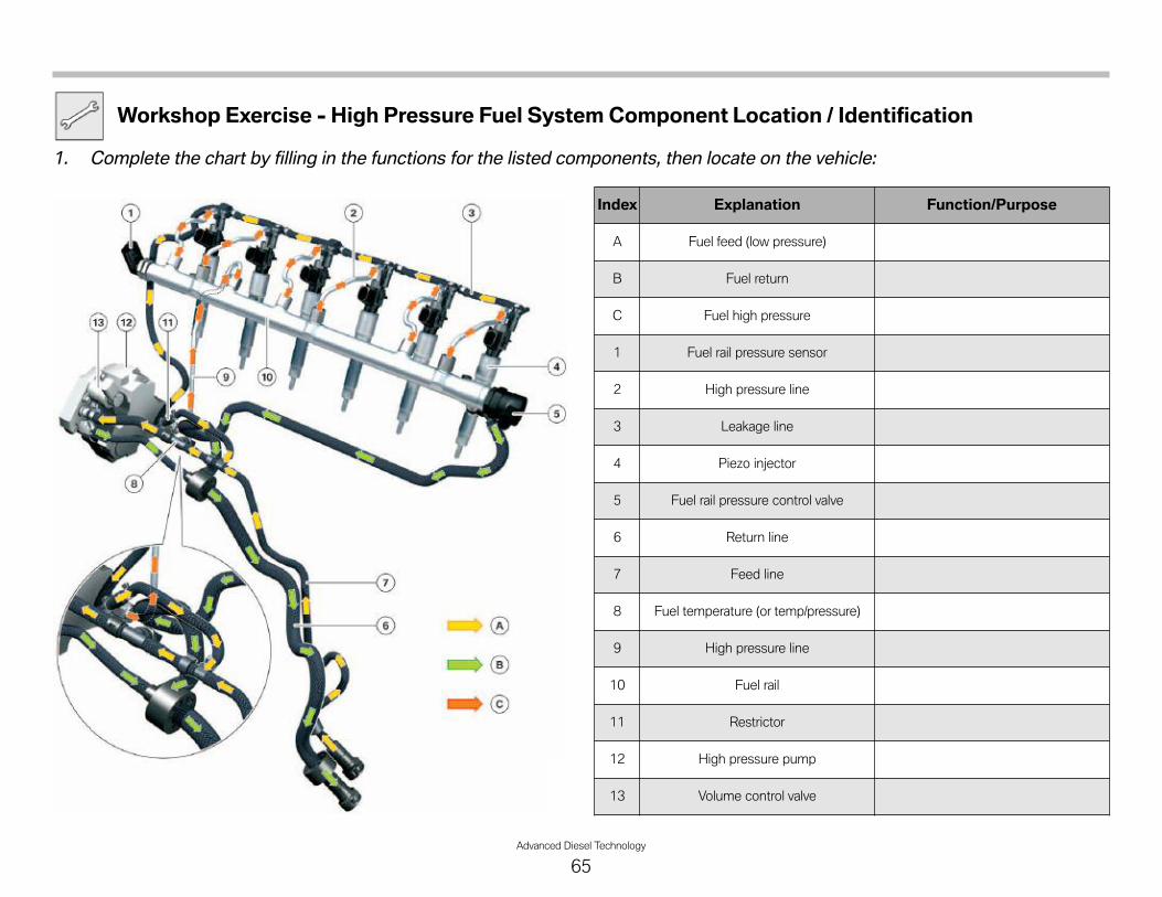
Advanced Diesel Technology
65
Workshop Exercise - High Pressure Fuel System Component Location / Identification
1. Complete the chart by filling in the functions for the listed components, then locate on the vehicle:
Index Explanation Function/Purpose
A Fuel feed (low pressure)
B Fuel return
C Fuel high pressure
1 Fuel rail pressure sensor
2 High pressure line
3 Leakage line
4 Piezo injector
5 Fuel rail pressure control valve
6 Return line
7 Feed line
8 Fuel temperature (or temp/pressure)
9 High pressure line
10 Fuel rail
11 Restrictor
12 High pressure pump
13 Volume control valve
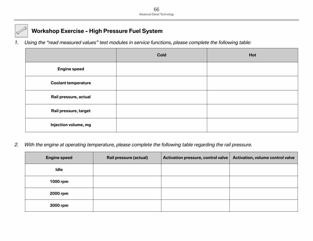
Workshop Exercise - High Pressure Fuel System
1. Using the “read measured values” test modules in service functions, please complete the following table:
2. With the engine at operating temperature, please complete the following table regarding the rail pressure.
66Advanced Diesel Technology
Cold Hot
Engine speed
Coolant temperature
Rail pressure, actual
Rail pressure, target
Injection volume, mg
Engine speed Rail pressure (actual) Activation pressure, control valve Activation, volume control valve
Idle
1000 rpm
2000 rpm
3000 rpm

Advanced Diesel Technology
67
Workshop Exercise - High Pressure Fuel System
3. Disconnect the rail pressure sensor and note the substitute value. Substitute value -
Is there any change to engine operation?
4. Complete the test module for the rail pressure regulation valve. Record the resistance values in the chart below:
5. Disconnect the volume control valve. Does the engine run? Explain why or why not?
6. Disconnect the pressure control valve? Does the engine run? Explain why or why not?
Nominal value Actual value

68Advanced Diesel Technology
Workshop Exercise - High Pressure Fuel System
7. Perform the test module for the high pressure pump and complete the following chart:
While performing above test module, obtain the oscilloscope pattern for the high pressure pump. Draw the pattern on thescope illustration provided.
Amplitude (maximum) Period duration
Item Value
Test connections (MFK)
Frequency settings
Voltage level
Trigger level

Advanced Diesel Technology
69
Workshop Exercise - High Pressure Fuel System
8. Obtain an oscilloscope pattern of the piezo injector and sketch your result below:
High voltage may be present.
Record Settings in the chart below:
9. Measure the resistance values of all injectors and record below:
WARNING!!!
Item Value
Test connections (MFK)
Frequency settings
Voltage level
Trigger level
Injector 1 Injector 2 Injector 3 Injector 4 Injector 5 Injector 6
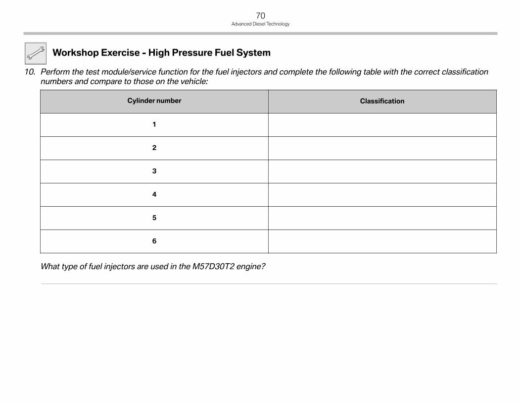
70Advanced Diesel Technology
Workshop Exercise - High Pressure Fuel System
10. Perform the test module/service function for the fuel injectors and complete the following table with the correct classificationnumbers and compare to those on the vehicle:
What type of fuel injectors are used in the M57D30T2 engine?
Cylinder number Classification
1
2
3
4
5
6

Advanced Diesel Technology
71
NOTESPAGE

1. Which of the components listed below direct fuel to thereturn circuit for the operation of the siphon jet in the fueltank? (circle those that apply)
Leakage line Volume control valve
Rail pressure control valve Restrictor
Fuel injectors Fuel filter
2. In order to refuel a BMW diesel vehicle, there is a flap in thefuel tank to prevent misfueling. What is the correct diameterof the diesel fuel nozzle which is necessary to operate themisfueling flap? (circle one)
19 mm 21 mm 24 mm 34 mm
3. Which of the following components is NOT used on adiesel fuel system? (circle those that apply)
Electric fuel pump Charcoal canister Fuel filter
EKP module Siphon jet DM-TL
4. In order for the piezo injector to operate correctly, thepressure in the leakage circuit must be: (circle one)
100 bar or greater Approximately 10 bar
3 to 5 bar 100 millibar
200 bar 1 bar +/- 100 millibar
5. In order to maintain the adequate pressure in the leakageline, a _______________________ is installed after the fuelinjectors. (circle one)
check valve non-return valve restrictor
solenoid bypass valve coupler
6. For the US version of the diesel, which of the following fuelsystem components has been adapted to meet the USspecific fuel specifications? (circle all that apply)
High pressure pump Fuel filter
Volume control valve Leakage line
Electric fuel pump Fuel injectors
Fuel rail Fuel filter heater
72Advanced Diesel Technology
Classroom Exercise - Review Questions

Advanced Diesel Technology
73
Classroom Exercise - Review Questions
7. Complete the following chart by checking the box for eitherE70 or E90 where it applies:
Component/System E70Xdrive35d E90 335d
Screw-spindle fuel pump
Gear-type (rotor) fuel pump
Speed controlled low pressure fuel system
Pressure controlled low pressure fuel system
Fuel temperature/pressure sensor
Fuel temperature sensor
Low pressure EGR system
High-pressure EGR system
SCR system
Diesel particulate filter
Low pressure EGR cooler
High pressure EGR cooler

74Advanced Diesel Technology
Legislation
Since the first exhaust emission legislation for petrol engines came into force in the mid-1960s in California, the permissible limits for arange of pollutants have been further and further reduced. In the meantime, all industrial nations have introduced exhaust emissionlegislation that defines the emission limits for petrol and diesel engines as well as the test methods.
Essentially, the following exhaust emission legislation applies:
• CARB legislation (California Air Resources Board), California
• EPA legislation (Environmental Protection Agency), USA
• EU legislation (European Union) and corresponding ECE regulations (UN Economic Commission for Europe), Europe
• Japan legislation.
This legislation has lead to the development of different requirements with regard to the limitation of various components inthe exhaust gas. Essentially, the following exhaust gas constituents are evaluated:
• Carbon monoxide (CO)
• Nitrogen oxides (NOx)
• Hydrocarbons (HC)
• Particulates (PM)
It can generally be said that traditionally more emphasis is placed on low nitrogen oxide emissions in US legislation while in Europe thefocus tends to be more on carbon monoxide. The following graphic compares the standard applicable to BMW diesel vehicles with thecurrent standards in Europe. A direct comparison, however, is not possible as different measuring cycles are used and different valuesare measured for hydrocarbons.
Although European and US standards cannot be compared 1:1 it is clear that requirements relating to nitrogen oxide emissions are con-siderably more demanding in the US market. Diesel engines generally have higher nitrogen oxide emission levels than petrol engines asdiesel engines are normally operated with excess air. For this reason, the challenge of achieving approval in all 50 states of the USA hadto be met with a series of new technological developments.
Diesel Emission Control Systems

Advanced Diesel Technology
75
Standard Validfrom
CO[mg/km]
NOx[mg/km]
HC+NOx *[mg/km]
NMHC **[mg/km]
PM[mg/km]
EURO 4 1-1-05 500 250 300 - 25
EURO 5 9-1-09 500 180 230 - 5
EURO 6 9-1-14 500 80 170 - 5
LEV II MY 2005 2110 31 - 47 6
Comparison of Exhaust Emission Legislation
* In Europe, the sum of nitrogen oxide and hydrocarbons isevaluated, i.e. the higher the HC.
** In the USA, only the methane-free hydrocarbons areevaluated, i.e. all hydrocarbons with no methane.

76Advanced Diesel Technology
Exhaust Gas Recirculation
The recycling of exhaust gases is one of the methods used toreduce NOx in a diesel engine. By introducing exhaust gas into theintake stream, the amount of oxygen in the combustion chamber isreduced which results in lower combustion chamber temperatures.
The EGR systems differ between the E70 and the E90. Both vehi-cles use the “high-pressure EGR”, but the E70 uses an additional“low-pressure EGR” system. The low pressure EGR system isrequired in the E70 due to it’s additional weight and higher opera-tional loads (i.e. towing etc.).
Low Pressure EGRThe known EGR system has been expanded by the low pressureEGR on the E70. This system offers advantages particularly athigh loads and engine speeds. This is why it is used in the heavierE70 as it is often driven in the higher load ranges.
The advantage is based on the fact that a higher total mass ofexhaust gas can be recirculated. This is made possible for tworeasons:
• Lower exhaust gas temperature - The exhaust gas for the lowpressure EGR is tapped off at a point where a lower tempera-ture prevails than in the high pressure EGR. Consequently,the exhaust gas has a higher density thus enabling a highermass.
In addition, the exhaust gas is added to the fresh intake airbefore the exhaust turbocharger, i.e. before the intercooler,where it is further cooled. The lower temperature of the totalgas enables a higher EGR rate without raising the temperaturein the combustion chamber.
• Recirculation before the exhaust turbocharger - Unlike in thehigh pressure EGR where the exhaust gas is fed to the chargeair already compressed, in this system the exhaust gas isadded to the intake air before the exhaust turbocharger.A lower pressure prevails in this area under all operating condi-tions.
This makes it possible to recirculate a large volume of exhaustgas even at higher engine speed and load whereas this islimited by the boost pressure in the high pressure EGR.
Low pressure EGR system

Advanced Diesel Technology
77
The following graphic shows the control of the EGR system withlow pressure EGR:
As already mentioned, the low pressure EGR has the greatestadvantage at higher loads and is therefore activated, as a functionof the characteristic map, only in this operating mode.
The low pressure EGR, however, is never active on its own butrather always operates together with the high pressure EGR.
Added to this, it is only activated at a coolant temperature of morethan 55°C. The low pressure EGR valve is closed as from acertain load level so that only the high pressure EGR valve is activeagain. This means the EGR rate is continuously reduced.
The low pressure EGR system is located on the right-hand side onthe engine directly next to the diesel particulate filter and the lowpressure stage of the turbo assembly. The exhaust gas is branchedoff directly after the diesel particulate filter and fed to the intake airbefore the compressor for the low pressure stage.
Index Explanation Index Explanation
1 No EGR 3 High and low pressure EGRare active
2 Only high pressure EGR is activeIndex Explanation Index Explanation
1 DPF 4 Low pressure EGR
2 Turbocharger assembly 5 Exhaust system
3 Exhaust turbocharger,low pressure stage
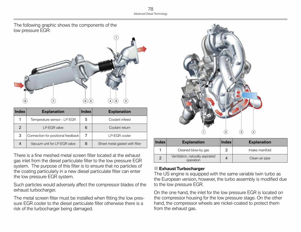
78Advanced Diesel Technology
The following graphic shows the components of thelow pressure EGR:
There is a fine meshed metal screen filter located at the exhaustgas inlet from the diesel particulate filter to the low pressure EGRsystem. The purpose of this filter is to ensure that no particles ofthe coating particularly in a new diesel particulate filter can enterthe low pressure EGR system.
Such particles would adversely affect the compressor blades of theexhaust turbocharger.
The metal screen filter must be installed when fitting the low pres-sure EGR cooler to the diesel particulate filter otherwise there is arisk of the turbocharger being damaged.
ExhaustTurbochargerThe US engine is equipped with the same variable twin turbo asthe European version, however, the turbo assembly is modified dueto the low pressure EGR.
On the one hand, the inlet for the low pressure EGR is located onthe compressor housing for the low pressure stage. On the otherhand, the compressor wheels are nickel-coated to protect themfrom the exhaust gas.
Index Explanation Index Explanation
1 Cleaned blow-by gas 3 Intake manifold
2 Ventilation, naturally aspiratedoperation 4 Clean-air pipe
Index Explanation Index Explanation
1 Temperature sensor - LP EGR 5 Coolant infeed
2 LP-EGR valve 6 Coolant return
3 Connection for positional feedback 7 LP-EGR cooler
4 Vacuum unit for LP-EGR valve 8 Sheet metal gasket with filter

Advanced Diesel Technology
79
High Pressure EGRThe exhaust gas recirculation known to date is referred to here asthe high pressure EGR in order to differentiate it from the lowpressure EGR.
Compared to the European version, the high pressure EGR isequipped with the following special features:
• Electric EGR valve with positional feedback
• Temperature sensor before high pressure EGR valve
• EGR cooler with bypass.
The electric actuating system of the EGR valve enables exactmetering of the recirculated exhaust gas quantity. In addition, thisquantity is no longer calculated based solely on the signals fromthe hot-film air mass meter and oxygen sensor but the followingsignals are also used:
• Travel of high pressure EGR valve
• Temperature before high pressure EGR valve
• Pressure difference between exhaust gas pressure in theexhaust manifold and boost pressure in the intake manifold.
This enables even more exact control of the EGR rate.
The EGR cooler serves the purpose of increasing the efficiency ofthe EGR system. However, reaching the operating temperature asfast as possible has priority at low engine temperatures.
In this case, the EGR cooler can be bypassed in order to heat upthe combustion chamber faster. For this purpose, there is a bypassthat diverts the flow of the exhaust around the EGR cooler.
This bypass is actuated by a flap which, in turn, is operated by avacuum unit. The bypass is either only in the "Open" or "Closed"position.
Index Explanation Index Explanation
1 Coolant inlet 5 High pressure EGR cooler
2 High pressure EGR valve 6 Vacuum unit of bypass valve for HP-EGR cooler
3 Throttle valve 7 Coolant return
4 Temperature sensor, HP-EGR
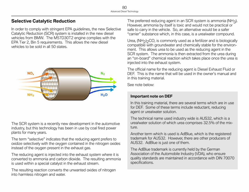
80Advanced Diesel Technology
Selective Catalytic Reduction
In order to comply with stringent EPA guidelines, the new SelectiveCatalytic Reduction (SCR) system is installed in the new dieselvehicles from BMW. The M57D30T2 engine complies with theEPA Tier 2, Bin 5 requirements. This allows the new dieselvehicles to be sold in all 50 states.
The SCR system is a recently new development in the automotiveindustry, but this technology has been in use by coal fired powerplants for many years.
The term “selective” indicates that the reducing agent prefers tooxidize selectively with the oxygen contained in the nitrogen oxidesinstead of the oxygen present in the exhaust gas.
The reducing agent is injected into the exhaust system where it isconverted to ammonia and carbon dioxide. The resulting ammoniais used within a special catalyst in the exhaust stream.
The resulting reaction converts the unwanted oxides of nitrogeninto harmless nitrogen and water.
The preferred reducing agent in an SCR system is ammonia (NH3).However, ammonia by itself is toxic and would not be practical orsafe to carry in the vehicle. So, an alternative would be a safer“carrier” substance which, in this case, is a urea/water compound.
Urea, (NH2)2CO, is commonly used as a fertilizer and is biologicallycompatible with groundwater and chemically stable for the environ-ment. This allows urea to be used as the reducing agent in theSCR system. The ammonia is then extracted from the urea duringan “on-board” chemical reaction which takes place once the urea isinjected into the exhaust system.
The official name for the reducing agent is Diesel Exhaust Fluid orDEF. This is the name that will be used in the owner’s manual andin this training material.
See note below:
p
Important note on DEF
In this training material, there are several terms which are in usefor DEF. Some of these terms include reductant, reducingagent or urea/water solution.
The technical name used industry wide is AUS32, which is aurea/water solution of which urea comprises 32.5% of the mix-ture.
Another term which is used is AdBlue, which is the registeredtrademark for AUS32. However, there are other producers ofAUS32. AdBlue is just one of them.
The AdBlue trademark is currently held by the GermanAssociation of the Automobile Industry (VDA), who ensurequality standards are maintained in accordance with DIN 70070specifications.

Advanced Diesel Technology
81
SCROverview - SimplifiedSelective catalytic reduction is a system for reducing nitrogenoxides (NOx) in the exhaust gas. For this purpose, a reducingagent (urea/water solution) is injected into exhaust gas downstreamof the diesel particulate filter.
The nitrogen oxide reduction reaction then takes place in the SCRcatalytic converter. The urea-water solution is carried in two reser-voirs in the vehicle. The quantity is measured out such that it issufficient for one oil change interval.
The following graphic shows a simplified representationof the system:
The reason for using two reservoirs is that the urea-water solutionfreezes at a temperature of -11°C (12.2°F). For this reason, thesmaller “active” reservoir is heated but the larger passive reservoiris not. In this way, the entire volume of the urea-water solutionneed not be heated, thus saving energy. The amount in the activetank is sufficient, however, to cover large distances.
The small, heated reservoir is referred to as the active reservoir.A pump conveys the urea-water solution from this reservoir to themetering module. This line is also heated.
The larger, unheated reservoir is the passive reservoir. A transferpump regularly conveys the urea-water solution from the passivereservoir to the active reservoir.
Index Explanation Index Explanation
1 Passive reservoir 10 Transfer pump
2 Level sensors 11 Filter
3 Filler pipe, passive tank 12 Transfer line
4 Metering line 13 Metering module
5 Metering line heater 14 Level sensor
6 Pump 15 Filler pipe, active reservoir
7 Function unit 16 Exhaust system
8 Heater, in active tank 17 SCR catalytic converter
9 Active tank
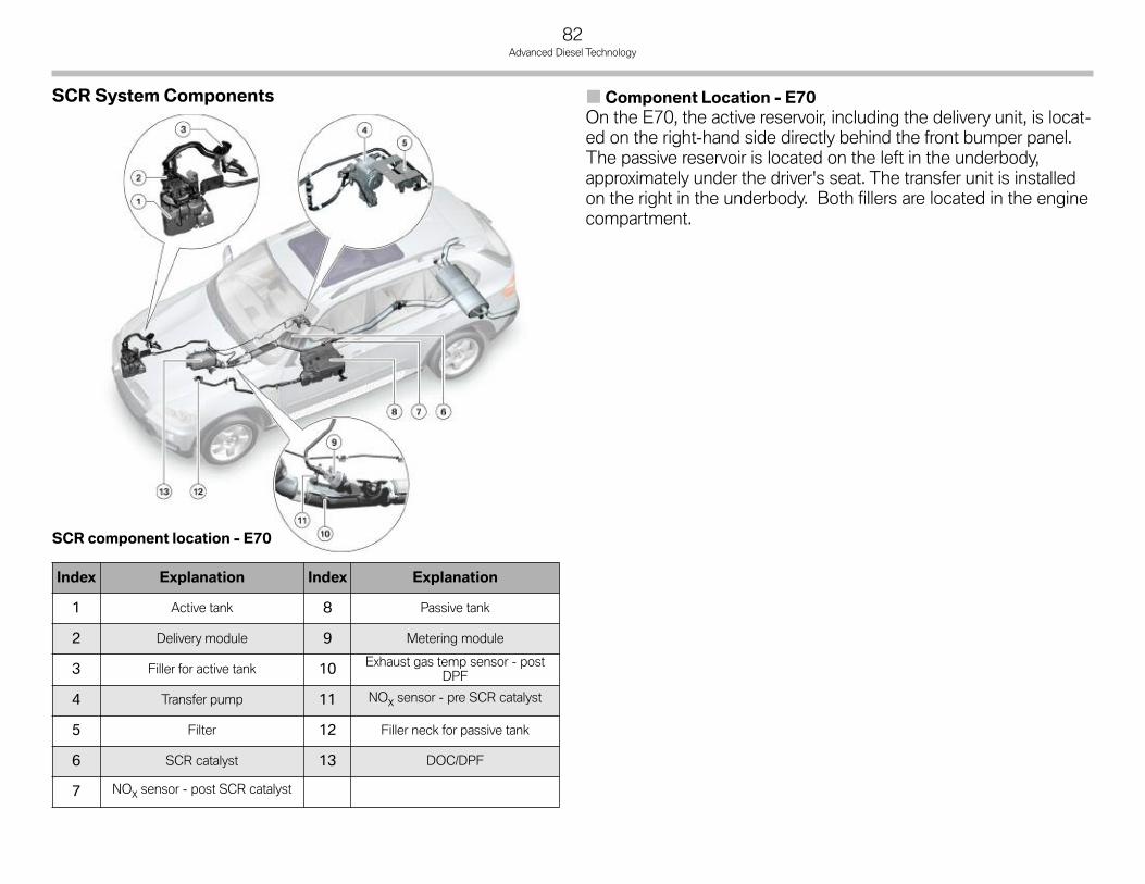
82Advanced Diesel Technology
SCR System Components Component Location - E70On the E70, the active reservoir, including the delivery unit, is locat-ed on the right-hand side directly behind the front bumper panel.The passive reservoir is located on the left in the underbody,approximately under the driver's seat. The transfer unit is installedon the right in the underbody. Both fillers are located in the enginecompartment.
Index Explanation Index Explanation
1 Active tank 8 Passive tank
2 Delivery module 9 Metering module
3 Filler for active tank 10 Exhaust gas temp sensor - postDPF
4 Transfer pump 11 NOx sensor - pre SCR catalyst
5 Filter 12 Filler neck for passive tank
6 SCR catalyst 13 DOC/DPF
7 NOx sensor - post SCR catalyst
SCR component location - E70

Advanced Diesel Technology
83
Component Location - E90On the E90, both the active reservoir as well as the passive reser-voir are located under the luggage compartment floor with theactive reservoir being the lowermost of both.
The fillers are located on the left-hand side behind the rear wheelwhere they are accessible through an opening in the bumper panel.The fillers are arranged in the same way as the reservoirs, i.e. thelower most is the filler for the active reservoir. The transfer unit andthe filter are located behind the filler.
Index Explanation Index Explanation
1 Active tank 8 Passive tank
2 Delivery module 9 Metering module
3 Filler for active tank 10 Exhaust gas temp sensor - postDPF
4 Transfer pump 11 NOx sensor - pre SCR catalyst
5 Filter 12 Filler neck for passive tank
6 SCR catalyst 13 DOC/DPF
7 NOx sensor - post SCR catalyst
SCR component location - E90

84Advanced Diesel Technology
Passive ReservoirThe passive reservoir is the larger of the two supply reservoirs.The name passive reservoir refers to the fact that it is not heated.
The following components make up the passive reservoir:
• Level sensors (2x)
• Operating vent (2x on E90)
• Filler vent.
The passive reservoir on the E70 is encased in insulation as it ispositioned near the front of the exhaust system where the heattransfer to the urea-water solution would be very high.
Vehicle Volume Location Position of filler neck
E70 16.5 l In underbody, under driver’sseat (approximately)
In the engine compartment, leftside, under unfiltered air inlet
E90 14.4 l Under luggage compartmentfloor Left side in rear bumper
Index Explanation Index Explanation
1 Operating vent 5 Fill line connection
2 Filler vent 6 “empty” level sensor
3 “full” level sensor 7 Passive reservoir
4 Operating vent
Index Explanation Index Explanation
1 Connection for transfer line 5 Fill line connection
2 Operating vent 6 Filler vent
3 “full” level sensor 7 “empty” level sensor
4 Passive reservoir

Advanced Diesel Technology
85
Level SensorsThere are two level sensors in thepassive reservoir. One suppliesthe "Full" signal and the other the"Empty" signal.
The sensors make use of the con-ductivity of the urea-water solution.When these contacts are wettedwith urea-water solution the circuitis closed and current can flow,thus enabling a sensor signal.
The two level sensors send their signal to an evaluator. This evalu-ator filters the signals and recognizes, for example, sloshing of theurea-water solution and transfers a corresponding level signal tothe digital diesel electronics.
The "Full" level sensor is located at the top of the passive reservoir.Both contacts are wetted when the passive reservoir is completelyfilled and the sensor sends the "Full" signal.
The "Empty" level sensor is located at the bottom end of the pas-sive reservoir. The reservoir is considered to be "not empty" for aslong as the sensor is covered by urea-water solution. The evaluatordetects that the passive reservoir is empty when no sensor signal isreceived.
VentingThe passive reservoir is equipped with one operating vent (2 in theE90) and one filler vent. The operating vent is directed into theatmosphere. A so-called sintered filter tablet ensures that no impu-rities can enter the reservoir via the operating vent. This sinteredtablet consists of a porous material and serves as a filter that allowsparticles only up to a certain size to pass through.
The filler vent is directed into the filler pipe and therefore no filter isrequired.
Transfer UnitThe transfer unit pumps the urea-water solution from the passivereservoir to the active reservoir. There is a screen filter in the inletport of the pump.
This pump is designed as a diaphragm pump. It operates in asimilar way to a piston pump but the pump element is separatedfrom the medium by a diaphragm. This means there are no prob-lems regarding corrosion.
Index Explanation
1 Connection for transfer line topassive reservoir (inlet)
2 Electrical connection for pumpmotor
3 Connection for transfer line toactive reservoir (outlet)

86Advanced Diesel Technology
Active ReservoirThe active reservoir is the smaller of the two reservoirs and itsname refers to the fact that it is heated. In view of its small volume,little energy is required to heat the urea-water solution.
Index Explanation Index Explanation
1 Active reservoir 4 Filler vent
2 Operating vent 5 Fill line connection
3 Delivery module 6 Connection of transfer line frompassive reservoir
Vehicle Volume Location Position of filler neck
E70 6.4 lOn front, right side in sidepanel module between
bumper panel and wheel arch
In the engine compartment, on thefront right hand side
E90 7.4 lBehind rear axle differential,directly under the passive
reservoirLeft side in rear bumper panel
Active reservoir - E90
Active reservoir - E70
Index Explanation
1 Fill line connection, active reservoir
2 Delivery module
3 Metering line
4 Filler vent
5 Connection of transfer line frompassive reservoir
6 Active reservoir

Advanced Diesel Technology
87
Function UnitThe so-called function unit is located in the active reservoir. It hasthe external appearance of a surge chamber and accommodates aheater, filter and a level sensor. The delivery unit is attached to it.
Unlike a surge chamber in the fuel tank, the lower section of thefunction unit has slots. This chamber creates a smaller volume inthe reservoir that scarcely mixes with the urea-water solutionoutside the chamber.
There is a PTC heating element (positive temperature coefficient)in the base of the chamber that can heat up this smaller volume ata relatively fast rate. The intake line is also heated. In this way, theliquid urea-water solution can be made available for vehicle opera-tion even at the lowest temperatures.
The heating element in the chamber is connected to the heater forthe intake line to form one heating circuit. A power semiconductorsupplies the current for this heating circuit. The power semicon-ductor is controlled by the DDE. The DDE can determine thecurrent that flows across the heating elements and can thereforemonitor their operation.
The temperature sensor provides the signal for the heating controlsystem. It is designed as an NTC sensor (negative temperaturecoefficient). The temperature sensor is integrated at the bottomend of the level sensor.
Index Explanation Index Explanation
1 Level sensor 4 Intake line with heater
2 Heating element 5 Operating vent
3 Filter
Index Explanation
1 Operating vent
2 Bowl
3 Level sensor
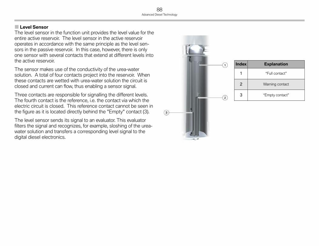
88Advanced Diesel Technology
Level SensorThe level sensor in the function unit provides the level value for theentire active reservoir. The level sensor in the active reservoiroperates in accordance with the same principle as the level sen-sors in the passive reservoir. In this case, however, there is onlyone sensor with several contacts that extend at different levels intothe active reservoir.
The sensor makes use of the conductivity of the urea-watersolution. A total of four contacts project into the reservoir. Whenthese contacts are wetted with urea-water solution the circuit isclosed and current can flow, thus enabling a sensor signal.
Three contacts are responsible for signalling the different levels.The fourth contact is the reference, i.e. the contact via which theelectric circuit is closed. This reference contact cannot be seen inthe figure as it is located directly behind the "Empty" contact (3).
The level sensor sends its signal to an evaluator. This evaluatorfilters the signal and recognizes, for example, sloshing of the urea-water solution and transfers a corresponding level signal to thedigital diesel electronics.
Index Explanation
1 “Full contact”
2 Warning contact
3 “Empty contact”
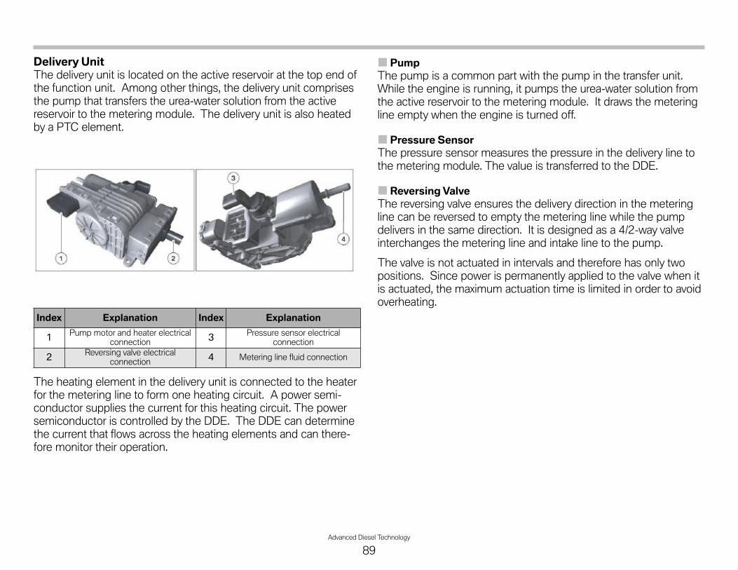
Advanced Diesel Technology
89
Delivery UnitThe delivery unit is located on the active reservoir at the top end ofthe function unit. Among other things, the delivery unit comprisesthe pump that transfers the urea-water solution from the activereservoir to the metering module. The delivery unit is also heatedby a PTC element.
The heating element in the delivery unit is connected to the heaterfor the metering line to form one heating circuit. A power semi-conductor supplies the current for this heating circuit. The powersemiconductor is controlled by the DDE. The DDE can determinethe current that flows across the heating elements and can there-fore monitor their operation.
PumpThe pump is a common part with the pump in the transfer unit.While the engine is running, it pumps the urea-water solution fromthe active reservoir to the metering module. It draws the meteringline empty when the engine is turned off.
Pressure SensorThe pressure sensor measures the pressure in the delivery line tothe metering module. The value is transferred to the DDE.
Reversing ValveThe reversing valve ensures the delivery direction in the meteringline can be reversed to empty the metering line while the pumpdelivers in the same direction. It is designed as a 4/2-way valveinterchanges the metering line and intake line to the pump.
The valve is not actuated in intervals and therefore has only twopositions. Since power is permanently applied to the valve when itis actuated, the maximum actuation time is limited in order to avoidoverheating.
Index Explanation Index Explanation
1 Pump motor and heater electricalconnection 3 Pressure sensor electrical
connection
2 Reversing valve electricalconnection 4 Metering line fluid connection

90Advanced Diesel Technology
Metering Module andMixerThe metering module is responsible for injecting the urea-watersolution into the exhaust pipe. It features a valve that is similar tothe fuel injector in a petrol engine with intake manifold injection.
Although the metering module does not have a heater, it is stillheated by the exhaust system to such an extent that it evenrequires cooling fins.
The metering module is actuated by a pulse-width modulated(PWM) signal from the DDE such that the pulse duty factor deter-mines the opening duration of the valve.
The metering module is equipped with a tapered insert (6) thatprevents urea-water solution residue drying up and clogging thevalve. Its shape creates a flow that prevents urea-water solutionfrom collecting on the walls of the exhaust system. Urea depositson the insert are burnt off as it is heated to very high temperaturesby the flow of exhaust gas.
MixerThe mixer mounted in the flange connection of the exhaust pipe islocated directly behind the metering module in the exhaust system.It swirls the flow of exhaust gas to ensure the urea-water solution isthoroughly mixed with the exhaust gas. This is necessary to ensurethe urea converts completely into ammonia.
Index Explanation Index Explanation
1 Metering line connection 2 Metering valve connection
Index Explanation Index Explanation
1 Mixer 4 DPF
2 NOx sensor - pre SCR catalyst 5 Metering module
3 Exhaust gas temperature sensorafter DPF 6 Insert

Advanced Diesel Technology
91
NOx SensorsThe nitrogen oxide sensor consists of the actual measuring probeand the corresponding control unit. The control unit communi-cates via the LoCAN with the engine control unit.
In terms of its operating principle, the nitrogen oxide can be com-pared with a broadband oxygen sensor. The measuring principle isbased on the idea of basing the nitrogen oxide measurement onoxygen measurement.
The exhaust gas flows through the NOx sensor. Here, only oxygenand nitrogen oxides are of interest. In the first chamber, the oxygenis ionized out of this mixture with the aid of the first pump cell andpassed through the solid electrolyte.
A lambda signal can be tapped off from the pump current of thefirst chamber. In this way, the exhaust gas in the NOx sensor isliberated from free oxygen (not bound to nitrogen).
The remaining nitrogen oxide then passes through the secondbarrier to reach the second chamber of the sensor. Here, the nitro-gen oxide is split by a catalytic element into oxygen and nitrogen.
The oxygen released in this way is again ionized and can then passthrough the solid electrolyte. The pump current that occurs duringthis process makes it possible to deduce the quantity of oxygenand the nitrogen level can be concluded from this quantity.
The following graphic shows the functional principle of thismeasuring system.
Index Explanation Index Explanation
1 Pump flow, 1st chamber 5 Barrier 2
2 Catalytic element 6Solid electrolyte Zircon dioxide
(ZrO2)
3 Nitrogen outlet 7 Barrier 1
4 Pump flow 2nd chamber

92Advanced Diesel Technology
Functions of the SCR SystemSelective catalytic reduction is currently the most effective systemfor reducing nitrogen oxides (NOx). During operation, it achieves anefficiency of almost 100% and approximately 90% over the entirevehicle operating range. The difference is attributed to the time thesystem requires until it is fully operative after a cold start.
This system carries a reducing agent, urea-water solution, in thevehicle. The urea-water solution is injected into the exhaust pipeby the metering module upstream of the SCR catalytic converter.
The DDE calculates the quantity that needs to be injected.The nitrogen oxide content in the exhaust gas is determined by theNOx sensor before the SCR catalytic converter.
Corresponding to this value, the exact quantity of the urea-watersolution required to fully reduce the nitrogen oxides is injected.The urea-water solution converts to ammonia in the exhaust pipe.
In the SCR catalytic converter, the ammonia reacts with thenitrogen oxides to produce nitrogen (N2) and water (H2O).
A further NOx sensor that monitors this function is located down-stream of the SCR catalytic converter.
A temperature sensor in the exhaust pipe after the diesel particu-late filter (i.e. before the SCR catalytic converter) and the meteringmodule also influences this function. This is because injection ofthe urea-water solution only begins at a minimum temperature of200°C (392°F).
Index Explanation Index Explanation
1 NOx sensor, pre catalyst 3 NOx sensor, post catalyst
2 Metering module 4 Temperature sensor after DPF
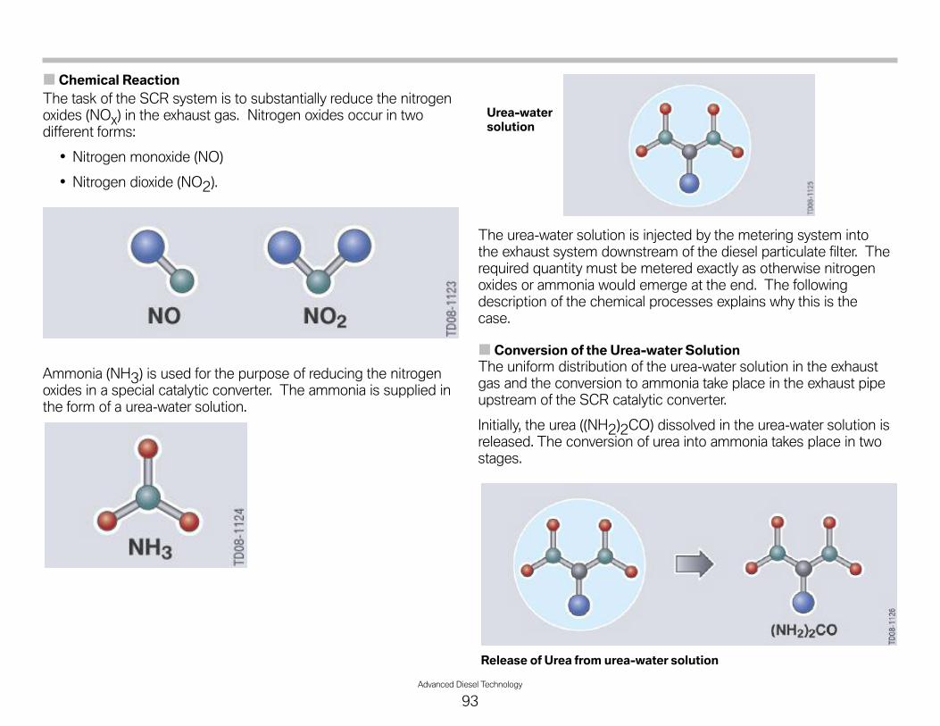
Advanced Diesel Technology
93
Chemical ReactionThe task of the SCR system is to substantially reduce the nitrogenoxides (NOx) in the exhaust gas. Nitrogen oxides occur in twodifferent forms:
• Nitrogen monoxide (NO)
• Nitrogen dioxide (NO2).
Ammonia (NH3) is used for the purpose of reducing the nitrogenoxides in a special catalytic converter. The ammonia is supplied inthe form of a urea-water solution.
The urea-water solution is injected by the metering system intothe exhaust system downstream of the diesel particulate filter. Therequired quantity must be metered exactly as otherwise nitrogenoxides or ammonia would emerge at the end. The followingdescription of the chemical processes explains why this is thecase.
Conversion of the Urea-water SolutionThe uniform distribution of the urea-water solution in the exhaustgas and the conversion to ammonia take place in the exhaust pipeupstream of the SCR catalytic converter.
Initially, the urea ((NH2)2CO) dissolved in the urea-water solution isreleased. The conversion of urea into ammonia takes place in twostages.
Release of Urea from urea-water solution
Urea-watersolution

94Advanced Diesel Technology
Hydrolysis
Explanation:
The isocyanic acid that was produced during thermoly-sis is converted into ammonia and carbon dioxide(CO2), by the addition of water in the hydrolysisprocess.
Initial Products:Isocyanic acid (HNCO)Water (H2O)
Result:Ammonia (NH3)Carbon dioxide (CO2)
ChemicalFormulas:
HNCO + H2O > NH3 + CO2
Hydrolysis: Isocyanic acid reacts with water to form ammonia and carbon dioxide
The water required for this purpose is also provided by theurea-water solution. Therefore, following hydrolysis, all the urea isconverted into ammonia and carbon dioxide.
Thermolysis
Explanation: During thermolysis, the urea-water solution is splitinto two products as a result of heating
Initial Products: Urea (NH2)2CO
Result:Ammonia (NH3)Isocyanic acid (HNCO)
Chemical Formulas: (NH2)2CO > NH3 = HNCO
Thermolysis: Urea converts to ammonia and isocyanic acid
This means, only a part of the urea-water solution is converted intoammonia during thermolysis. The remainder, which is in the formof isocyanic acid, is converted in a second step.
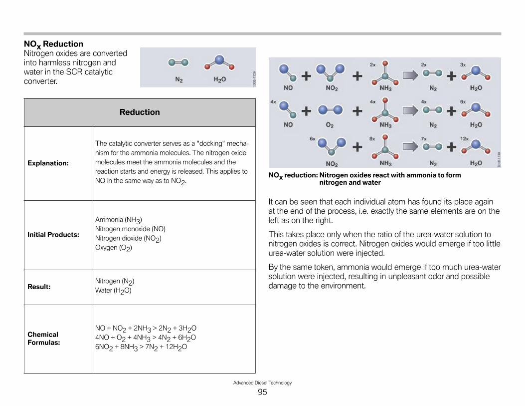
Advanced Diesel Technology
95
NOx ReductionNitrogen oxides are convertedinto harmless nitrogen andwater in the SCR catalyticconverter.
It can be seen that each individual atom has found its place againat the end of the process, i.e. exactly the same elements are on theleft as on the right.
This takes place only when the ratio of the urea-water solution tonitrogen oxides is correct. Nitrogen oxides would emerge if too littleurea-water solution were injected.
By the same token, ammonia would emerge if too much urea-watersolution were injected, resulting in unpleasant odor and possibledamage to the environment.
Reduction
Explanation:
The catalytic converter serves as a "docking" mecha-nism for the ammonia molecules. The nitrogen oxidemolecules meet the ammonia molecules and thereaction starts and energy is released. This applies toNO in the same way as to NO2.
Initial Products:
Ammonia (NH3)Nitrogen monoxide (NO)Nitrogen dioxide (NO2)Oxygen (O2)
Result:Nitrogen (N2)Water (H2O)
ChemicalFormulas:
NO + NO2 + 2NH3 > 2N2 + 3H2O4NO + O2 + 4NH3 > 4N2 + 6H2O6NO2 + 8NH3 > 7N2 + 12H2O
NOx reduction: Nitrogen oxides react with ammonia to formnitrogen and water

96Advanced Diesel Technology
SCR ControlThe SCR control is integrated in the digital diesel electronics (DDE).The SCR control is divided into the metering system control andthe metering strategy.
Index Explanation Index Explanation
1 DDE 7.3 10 Pressure sensor
2 SCR control 11 Temperature sensor in activereservoir
3 Metering system control 12 Outside temperature sensor
4 Metering strategy 13 Level sensor in active reservoir
5 Injection pump 14 Level sensor in passive reservoir
6 Transfer pump 15 NOx sensor - pre SCR catalyst
7 Metering module 16 NOx sensor - post SCR catalyst
8 Heater 17 Exhaust temperature sensor
9 Reversing valve

Advanced Diesel Technology
97
Metering StrategyThe metering strategy is an integral part of the SCR control thatcalculates how much urea-water solution is to be injected at whattime.
During normal operation, the signal from the NOx sensor before theSCR catalytic converter is used for the purpose of calculating thequantity. This sensor determines the quantity of nitrogen oxide inthe exhaust gas and sends the corresponding value to the DDE.
However, the NOx sensor must reach its operating temperaturebefore it can start measuring. Depending on the temperature, thiscan take up to 15 minutes. Until then the DDE uses a substitutevalue to determine the amount of nitrogen oxide in the exhaust gas.
A second NOx sensor is installed after the SCR catalytic converterfor the purpose of monitoring the system. It measures whetherthere are still nitrogen oxides in the exhaust gas. If so the injectedquantity of the urea-water solution is correspondingly adapted.
The NOx sensor, however, measures not only nitrogen oxides butalso ammonia but cannot distinguish between them. If too muchurea-water solution is injected, although the nitrogen oxides arecompletely reduced so-called "ammonia slip" occurs, i.e. ammoniaemerges from the SCR catalytic converter. This in turn causes arise in the value measured by the NOx sensor. The aim, therefore,is to achieve a minimum of the sensor value.
This, however, is a long-term adaptation and not a short-term con-trol process as the SCR catalytic converter performs a storagefunction for ammonia.
Index Explanation
A Value from NOx sensor
B Injected quantity of urea-watersolution
1 Too-little urea-water solutioninjected
2 Correct quantity of urea-watersolution injected
3 Too-much urea-water solutioninjected

98Advanced Diesel Technology
Metering System ControlThe metering system control could be considered as the executingpart. It carries out the requirements set by the metering strategy.
This includes both the metering, i.e. injection as well as the supplyof the urea-water solution.
The tasks of the metering system control during normal operationare listed in the following:
Metering of the urea-water solution:
• Implementation of the required target quantity of urea-watersolution
• Feedback of the implemented actual quantity of urea-watersolution.
Supplying urea-water solution:
• Preparation of metering process (filling lines and pressurebuilt-up) under corresponding ambient conditions (tempera-ture)
• Emptying lines during afterrunning
• Heater actuation.
In addition, the metering system control recognizes faults, implausi-ble conditions or critical situations and initiates correspondingmeasures.
Metering of the Urea-water SolutionThe metering strategy determines the quantity of urea-watersolution to be injected. The metering system control executes thisrequest. A part of the function is metering actuation that deter-mines the actual opening of the metering valve.
Depending on the engine load, the metering valve injects at a rateof 0.5 Hz to 3.3 Hz.
The metering actuation facility calculates the following factors inorder to inject the correct quantity:
• The duty factor of the actuator of the metering valve in order todetermine the injection duration
• Actuation delay to compensate for the reaction time of themetering valve.
The signal from the pressure sensor in the metering line is takeninto account to ensure an accurate calculation; the pressure,however, should remain at a constant 5 bar.
The metering system control also calculates the quantity actuallymetered and signals this value back to the metering strategy.
The metering quantity is also determined over a longer period oftime. This long-term calculation is reset during SCR refilling or canbe reset by the BMW diagnosis system.

Advanced Diesel Technology
99
Supplying Urea-water SolutionA supply of a urea-water solution is required for the selective cat-alytic reduction process. It is necessary to store this medium in thevehicle and to make it available rapidly under all operating condi-tions. In this case “making available” means that the urea-watersolution is applied at a defined pressure at the metering valve.
Various functions that are described in the following are required tocarry out this task.
HeaterThe system must be heated as the urea-water solution freezes at atemperature of -11°C.
The heating system performs following tasks:
• To monitor the temperature in the active reservoir and theambient temperature
• To thaw a sufficient quantity of urea-water solution and thecomponents required for metering the solution during systemstartup
• To prevent the relevant components freezing during operation
• To monitor the components of the heating system.
The following components are heated:
• Surge chamber in active reservoir
• Intake line in active reservoir
• Delivery module (pump, filter, reversing valve)
• Metering line (from active reservoir to metering module).
The heating systems for the metering line and delivery module arecontrolled dependent on the ambient temperature.
The heater in the active reservoir is controlled as a function of thetemperature in the active reservoir.
The heating control is additionally governed by the followingconditions:
Metering standby is delayed at a temperature below -9°C in theactive reservoir, i.e. a defined waiting period is allowed to elapseuntil an attempt to build up pressure begins.
This time is constant from -9°C to -16.5°C as it is not possible todetermine to what extent the urea-water solution is frozen.
At temperatures below -16.5°C, the heating time is extended untilan attempt to build up the pressure is made. Heating the meteringline generally takes place much faster.
Therefore, the temperature in the active reservoir is the decisivefactor for the period of time until an attempt to build up thepressure is undertaken.
However, it is possible that the heating time for the metering line islonger at ambient temperature considerably lower than the temper-ature in the active reservoir. In this case, the ambient temperature istaken for the delay in metering standby.
Temperature in active reservoir and ambient temperature are the same
Condition1
Condition2
Condition3
Condition4
Ambient temperature andtemperature in active reservoir > -4°C < -4°C < -5°C < -9°C
Metering line heater Not active Not active Active Active
Active reservoir heater Not active Active Active Active
Metering standby Established Established Established Delayed

100Advanced Diesel Technology
The following graphic shows the delay as a function of the temper-ature sensor signals.
The graphic shows that, with the same temperature signals, thedelay time relating to the temperature in the active reservoir islonger than the delay caused by the ambient temperature.
Only the times at temperatures below -9°C are relevant as they areshorter than 3 minutes at temperatures above -9°C. 3 minutes isthe time that the entire system requires to establish meteringstandby (e.g. also taking into account the temperature in the SCRcatalytic converter).
This is also the time that is approved by the EPA (EnvironmentalProtection Agency) as the preliminary period under all operatingconditions. This time is extended significantly at very low tempera-tures. The following example shows how the delay time up tometering standby is derived at low temperatures.
Example: Ambient temperature: -30°C, temperature in activereservoir: -12°C The vehicle was driven for a longer period of timeat very low ambient temperatures of - 30°C. The heater in theactive reservoir has thawed the urea-water solution.
The vehicle is now parked for a short period of time (e.g. 30 min-utes). When restarted, the temperature in the active reservoir isnow -12°C.
The delay time that is initiated by the temperature in the activereservoir is approximately 18 minutes while the delay time initiatedby the ambient temperature is 25 minutes. Since the delay timeinitiated by the ambient temperature is longer, this will give rise to alonger delay.
Now another condition comes into play. Only the end of the delaycaused by the temperature in the active reservoir can enablemetering. This means:
• The delay time initiated by the temperature in the active reser-voir will have elapsed after 18 minutes. No enable is yetprovided by the second delay caused by the ambient tempera-ture. A second cycle of 18 minutes now begins.
• The delay time initiated by the ambient temperature willelapse after 25 minutes and will send its enable signal.However, this delay cannot enable metering.
• The second cycle of the delay time caused by the tempera-ture in the active reservoir will have elapsed after 36 minutes.Since the enable from the delay caused by the ambient tem-perature is now applied, metering will be enabled.
Index Explanation Index Explanation
A Delay as a function of temperaturein active reservoir B Delay as a function of ambient
temperature
t [s] Delay time in seconds T[°C] Temperature in degrees Celsius

Advanced Diesel Technology
101
Transfer PumpingSo-called transfer pumping is required since two reservoirs areused for storing the urea-water solution. The term transfer pump-ing relates to pumping the urea-water solution from the passivereservoir into the active reservoir.
The following conditions must be met for transfer pumping:
• There is a urea-water solution in the passive reservoir
• The ambient temperature is above a minimum value of -5°Cfor at least 10 minutes
• A defined quantity (300 ml) was used up in the active reservoiror the reserve level in the active reservoir was reached.
The solution is then pumped for a certain time in order to refill theactive reservoir. The transfer pumping procedure is terminated ifthe "full" level is reached before the time has elapsed.
If the passive reservoir was refilled, transfer pumping will only takeplace after a quantity of approximately 3 liters has been used up inthe active reservoir. The entire quantity is then pumped over.
The system then waits again until a quantity of approximately3 liters has been used up in the active reservoir before againpumping the entire quantity while simultaneously starting the incor-rect refilling detection function.
This function determines whether the system has been filled withthe wrong medium as it is present in high concentration in theactive reservoir.
Transfer pumping does not take place in the event of a fault in thelevel sensor system.
Index Explanation Index Explanation
1 Passive reservoir 6 Pump
2 Level sensors 7 Non-return valve
3 Extractor connections 8 Level sensor
4 Transfer line 9 Active reservoir
5 Filter

102Advanced Diesel Technology
DeliveryThe urea-water solution is delivered from the active reservoir to themetering module. This task is performed by a pump that is inte-grated in the delivery unit. The delivery unit additionally contains:
• Heater
• Pressure sensor
• Filter
• Return throttle
• Reversing valve.
The pump is actuated by a pulse-width modulated signal (PWMsignal) from the DDE. The PWM signal provides a speed specifica-tion for the purpose of establishing the system pressure. The valuefor the speed specification is calculated by the DDE based on thesignal from the pressure sensor.
When the system starts up, the pump is actuated with a definedPWM signal and the line to the metering module is filled. This isfollowed by pressure build-up. Only then does pressure controltake place.
Index Explanation Index Explanation
1 Metering line 8 Filter
2 Delivery module 9 Level sensor
3 Pump 10 Filter
4 Reversing valve 11 SCR catalyst
5 Filter 12 Exhaust system
6 Restrictor 13 Metering module
7 Pressure sensor

Advanced Diesel Technology
103
When the metering line is filled, the opened metering valve allows asmall quantity of the urea-water solution to be injected into theexhaust system.
During pressure control, i.e. during normal operation with metering,the pump is actuated in such a way that a pressure of 5 bar isapplied in the metering line. Only a small part of the urea-watersolution delivered by the pump is actually injected.
The majority of the solution is transferred via a throttle back into theactive reservoir. This means, the delivery pressure is determinedby the pump speed together with the throttle cross section.
The solution is injected four times per second. The quantity isdetermined by the opening time and stroke of the metering valve.However, the quantity is so low that there is no noticeable drop inpressure in the metering line.
EvacuatingAfter turning off the engine, the reversing valve switches to reversethe delivery direction of the pump, thus evacuating the meteringline and metering module.
Evacuation also takes place if the system has to be shut down dueto a fault or if the minimum temperature in the active reservoir canno longer be maintained.
This is necessary to ensure no urea-water solution remains in themetering line or metering module as it can freeze.
The metering valve is opened during evacuation.
Index Explanation Index Explanation
1 Metering line 8 Filter
2 Delivery module 9 Level sensor
3 Pump 10 Filter
4 Reversing valve 11 SCR catalyst
5 Filter 12 Exhaust system
6 Restrictor (throttle) 13 Metering module
7 Pressure sensor

104Advanced Diesel Technology
Level MeasurementThere are level sensors both in the active as well as in the passivereservoir. However, these sensors are not continuous sensors as inthe fuel system for example. They can determine only a specificpoint, to which a defined quantity of urea-water solution in thereservoir is assigned.
Two separate level sensors are fitted in the passive reservoir, onefor "full" and one for "empty". The signals from the level sensorsare not sent directly to the DDE but rather to an evaluator.
The active reservoir contains one level sensor that has variousmeasuring points:
• Full
• Warning
• Empty.
Also in this case, there is an evaluator installed between thesensors and the DDE, which fulfils the same tasks as for the pas-sive reservoir.
This evaluator sends a plausible level signal to the DDE. It recog-nizes changes in the fill level caused, for example, by drivinguphill/downhill or sloshing of the liquid as opposed to an actualchange in the liquid level in the reservoir.
Low level is therefore signalled when the corresponding sensor isno longer covered by the urea-water solution for a defined period oftime. Once the level drops below this value, it can no longer bereached during normal operation. This means, the liquid sloshingon the sensor or driving uphill/downhill is no longer interpreted as ahigher liquid level.
The level measurement system must also recognize when theactive and passive reservoirs are refilled. This is achieved bycomparing the current level with the value last stored.
The level sensor signal after refilling corresponds to the signalwhile driving uphill. To avoid possible confusion, the refilling recog-nition function is limited to a certain period of time after starting theengine and driving off - as it can be assumed that refilling will onlytake place while the vehicle is stationary.
A certain vehicle speed must be exceeded to ensure that sloshingoccurs, thus providing a clear indication that the system has beenrefilled.
Index Explanation
1 Measuring point “full”
2 Measuring point “warning”
3 Measuring point “empty”
4 Reference
5 Level
Level of urea-water solution Level signal
Level > Full Full
Full > Level > Warning OK
Warning > Level > Empty Warning
Empty > Level Empty

Advanced Diesel Technology
105
Refilling the system while the engine is running can also be detect-ed but with modified logic. The signals sent by the sensors whilethe vehicle is stationary are also used for this purpose. The vehiclemust be stationary for a defined minimum period in order to makethe filling plausible.
When the urea-water solution is frozen, a level sensor will show thesame value as when it is not wetted/covered by the solution.A frozen reservoir is therefore shown as empty. For this reason, thefollowing sensor signals are used for measuring the level:
• Ambient temperature
• Temperature in active reservoir
• Heater enable.
Level CalculationThis function calculates the quantity of urea-water solution remain-ing in the active reservoir. The calculation is calibrated togetherwith the level measurement.
Every time the level drops below a level sensor the correspondingamount of urea-water solution in the reservoir is stored. Theamount of urea-water solution actually injected is then subtractedfrom this value while the pumped quantity is added.
This makes it possible to determine the level more precisely thanthat would be possible by simple measurement. In addition, thelevel can still be determined in the event of one of the level sensorsfailing.
Since it is possible that refilling is not recognized, the calculation iscontinued only until the level ought to drop below the next lowersensor.
Example:
Once the level drops below the "full" level sensor, for example, fromnow on the quantity of used and repumped urea-water solution istaken into account and the actual level below "full" calculated.
Normally, the level then drops below the next lower level sensor atthe same time as determined by the level calculation. An adjust-ment takes place at this point and the calculation is restarted.
If, however, a quantity of urea-water solution is refilled without itbeing detected, the actual level will be higher than the calculatedlevel. The level calculation is stopped if it calculates that the levelought to have dropped below the next level sensor but the levelsensor is still wetted/covered.
By way of exception, a defective level sensor can cause the calcula-tion to continue until the reservoir is empty.
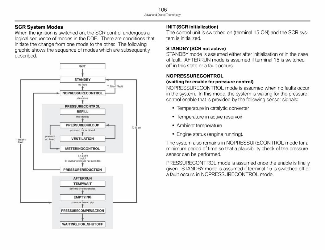
106Advanced Diesel Technology
SCR SystemModesWhen the ignition is switched on, the SCR control undergoes alogical sequence of modes in the DDE. There are conditions thatinitiate the change from one mode to the other. The followinggraphic shows the sequence of modes which are subsequentlydescribed.
INIT (SCR initialization)The control unit is switched on (terminal 15 ON) and the SCR sys-tem is initialized.
STANDBY (SCR not active)STANDBYmode is assumed either after initialization or in the caseof fault. AFTERRUN mode is assumed if terminal 15 is switchedoff in this state or a fault occurs.
NOPRESSURECONTROL(waiting for enable for pressure control)NOPRESSURECONTROL mode is assumed when no faults occurin the system. In this mode, the system is waiting for the pressurecontrol enable that is provided by the following sensor signals:
• Temperature in catalytic converter
• Temperature in active reservoir
• Ambient temperature
• Engine status (engine running).
The system also remains in NOPRESSURECONTROL mode for aminimum period of time so that a plausibility check of the pressuresensor can be performed.
PRESSURECONTROL mode is assumed once the enable is finallygiven. STANDBYmode is assumed if terminal 15 is switched off ora fault occurs in NOPRESSURECONTROL mode.

Advanced Diesel Technology
107
PRESSURECONTROL (SCR system running)PRESSURECONTROL mode is the normal operating status of theSCR system and has four submodes.
PRESSURECONTROL mode is maintained until terminal 15 isswitched off. A change to PRESSUREREDUCTION mode thentakes place. A change to PRESSUREREDUCTION mode alsotakes place if a fault occurs in the system.
The four submodes of PRESSURECONTROL are described in thefollowing:
• REFILL
The delivery module, metering line and the metering moduleare filled when REFILL mode is assumed. The pump is actu-ated and the metering valve opened by a defined value.The fill level is calculated.
The mode changes to PRESSUREBUILDUP when therequired fill level is reached or a defined pressure increase isdetected.
PRESSUREREDUCTION mode is assumed if terminal 15 isswitched off or a fault occurs in the system.
• PRESSUREBUILDUP
In this mode, the pressure is built up to a certain value. For thispurpose, the pump is actuated while the metering valve isclosed.
If the pressure is built up within a certain time, the systemswitches to the next mode of METERINGCONTROL. If therequired pressure built-up is not achieved after the definedperiod of time has elapsed, a status loop is initiated, and VEN-TILATION mode is assumed.
If the pressure cannot be built up after a defined number ofattempts, the system signals a fault and assumes PRESSUR-EREDUCTION mode.
PRESSUREREDUCTION mode is also assumed when termi-nal 15 is switched off or another fault occurs in the system.
• VENTILATION
If the pressure could not be increased beyond a certain valuein PRESSUREBUILDUP mode, it is assumed that there is stillair in the pressure line.
The metering valve is opened for a defined period of time toallow this air to escape. This status is exited after this time haselapsed and the system returns to PRESSUREBUILDUPmode. The loop between PRESSUREBUILDUP and VENTI-LATION varies corresponding to the condition of the reducingagent. The reason for this is that a different level is establishedafter REFILL depending on the ambient conditions. Repeatingthe ventilation function will ensure that the pressure line iscompletely filled with reducing agent. PRESSUREREDUC-TION mode is assumed if terminal 15 is switched off or a faultoccurs in the system.
• METERINGCONTROL
The system can enable metering in METERINGCONTROLmode. This is the actual status during normal operation.The urea-water solution is injected in this mode. In this mode,the pump is actuated in such a way that a defined pressure isestablished. This pressure is monitored. If the pressure pro-gression overshoots or undershoots defined parameters, afault is detected and the system assumes PRESSURERE-DUCTION mode. These faults are reset on return to METER-INGCONTROL mode.
PRESSUREREDUCTION mode is also assumed if terminal 15is switched off or another fault occurs in the system.

108Advanced Diesel Technology
PRESSUREREDUCTIONMetering enable is cancelled on entering PRESSUREREDUCTIONmode.
This status reduces the pressure in the delivery module, meteringline and the metering module after PRESSURECONTROL mode.For this purpose, the reversing valve is opened and the pump actu-ated at a certain value, the metering valve is closed.
PRESSUREREDUCTION mode ends when the pressure dropsbelow a certain value. The system assumes NOPRESSURECON-TROL mode if the pressure threshold is reached (undershot) withina defined time.
The system signals a fault if the pressure does not drop below thethreshold after a defined time has elapsed. In this case or also inthe case of another fault, the system assumes NOPRESSURE-CONTROL mode. NOPRESSURECONTROL mode is alsoassumed when terminal 15 is switched on.
AFTERRUNThe system is shut down in AFTERRUN mode. If terminal 15 isswitched on again before afterrun has been completed, afterrun iscancelled and STANDBYmode is assumed. If this is not the casethe system goes through the submodes of AFTERRUN.
• TEMPWAIT (catalytic converter cooling phase)
In AFTERRUN mode, TEMPWAIT submode is initiallyassumed if the system is filled. This is intended to preventexcessively hot exhaust gasses being drawn into the SCRsystem.
The duration of the cooling phase is determined by theexhaust gas temperature. EMPTYING submode is assumedafter this time, in which the exhaust system cools down, haselapsed. EMPTYING submode is also assumed if a faultoccurs in the system. If terminal 15 is switched on in this sta-tus, STANDBYmode is assumed.
• EMPTYING
The system assumes AFTERRUN_EMPTYING submodeafter the cooling phase. The pressure line and the deliverymodule are emptied in this submode. The urea-water solutionis drawn back into the active reservoir by opening the revers-ing valve, actuating the pump and opening the metering valve.
This is intended to prevent the urea-water solution freezing inthe metering line or the metering module. The level in themetering line is calculated in this mode.
PRESSURECOMPENSATION mode is assumed if the meter-ing line is empty. PRESSURECOMPENSATION mode is alsoassumed if a fault occurs in the system. If terminal 15 isswitched on, STANDBYmode is assumed.
• PRESSURECOMPENSATION(intake line - ambient pressure)
After the system has been completely emptied, PRES-SURECOMPENSATION submode is assumed. In this statusthe pump is switched off, the reversing valve is then closedfollowed by the metering valve after a delay. The time intervalbetween switching off the pump and closing the valveprevents a vacuum forming in the intake line; pressure com-pensation between the intake line and ambient pressure takesplace.
After executing the steps correctly the system assumes WAIT-ING_FOR_SHUTOFF submode. WAITING_FOR_SHUTOFFis also assumed if a fault occurs in the system. If terminal 15 isswitched on, STANDBYmode is assumed.
• WAITING_FOR_SHUTOFF (shutting down SCR)
The control unit is shut down and switched off.

Advanced Diesel Technology
109
NOTESPAGE

110Advanced Diesel Technology
Warning and Shut-down ScenarioThe SCR system is relevant to the vehicle complying with the exhaust emission regulations - it is a prerequisite for EPA approval.
If the system fails, the approval will be invalidated and the vehicle must no longer be operated. A very plausible case leading to the systemfailure is that the urea-water solution runs out.
Vehicle operation is no longer permitted without the urea-water solution, therefore, the engine will no longer start. To ensure the driver isnot caught out, a warning and shut-down scenario is provided that begins at a sufficiently long time before the vehicle actually shuts downso that the driver can either conveniently top up the urea-water solution himself or have it topped up.
Warning ScenarioThe warning scenario begins when the level drops below the "Warning" level sensor in the active reservoir. At this point, the active reser-voir is still approximately 50% full with urea-water solution. The level is then determined as a defined volume (depending on type of vehi-cle).
From this point on, the actual consumption of the urea-water solution is subtracted from this value. The mileage is recorded when theamount of 2500 ml is reached.
A countdown from 1000 mls now takes place irrespective of the actual consumption of the urea-water solution. The driver receives apriority 2 (yellow) check control message showing the remaining range.
If the vehicle is equipped with an on-board computer (CID - Central Information Display), instruction will also be displayed. The driverreceives a priority 1 (red) check control message as from 200 mls.
The following messages and indicators will be displayed:
CCmessage in clus-ter, range < 1000miles
CCmessage in CID, range < 1000miles
CCmessage in clus-ter, range <200miles
CCmessage in CID, range < 200miles

Advanced Diesel Technology
111
Shut-down ScenarioIf the range reaches 0 mls, similar as to in the fuel gauge, three dashes are shown instead of the range. The check control message in theCID changes and shows that the engine can no longer be started.
In this case, it will no longer be possible to start the engine if it has been shut down for longer than three minutes. This is intended to allowthe driver to move out of a hazardous situation if necessary.
If the system is refilled only after engine start has been disabled, the logic of the refill recognition system is changed in this special case,enabling faster refill.
Exhaust Fluid IncorrectIf the system is filled with an incorrect medium, this will become apparent after several hundred miles (kilometers) later by elevatednitrogen oxide values in the exhaust gas despite adequate injection of the supposed urea-water solution. The system recognizes an incor-rect medium when certain limits are exceeded. From this point on, a warning and shut-down scenario is also initiated that allows aremaining range of 200 mls.
The exclamation mark in the symbol identifies the fault in the system. In this case, the message in the CID informs the driver to go to thenearest workshop.
CCmessage in clus-ter, range = 0miles
CCmessage in CID, range 0miles
CCmessage in clus-ter, in case of incor-rect DEF
CCmessage in CID, in case of incorrect DEF

112Advanced Diesel Technology
RefillingThe active and passive reservoirs can be refilled with urea-watersolution either by the service workshop or by the customer himself.
The system can be refilled without any problems with the vehicleon an incline of up to 5° in any direction. In this case, 90% of themaximum possible fill is still achieved.
The volume of the urea-water solution reservoir is designed suchthat the range is large enough to cover one oil change interval.This means the "normal" refill takes place as part of the servicingwork in the workshop. If, however, the supply of urea-water solutionshould run low prematurely due to extraordinary driving profile, it ispossible to top up a smaller quantity.
Refilling in ServiceWorkshopRefilling in the service workshop refers to the routine refill as part ofthe oil change procedure. This takes place at the latest after:
• 13000 mls on the E90,
• 11000 mls on the E70 or
• one year.
In this case, the system must be emptied first in order to removeolder urea-water solution. This takes place via the extractorconnections in the transfer line. Although a small residual quantityalways remains in the reservoirs, it is negligible.
Topping UpAny required quantity can be topped up if the urea-water solutionreserve does not last up to the next oil change. Ideally, this quantityshould only be as much as is required to reach the next oil change,as the system is then emptied.
Diesel Exhaust FluidThe diesel exhaust fluid (DEF) is a urea-water solution which actsas a the carrier for the ammonia that is used to reduce the nitrogenoxides (NOx) in the exhaust gas.
To protect persons and the environment from the effects of ammo-nia and to make it more easy to handle for transport and refuellingprocedures, it is provided in an aqueous urea solution for the SCRprocess.
The recommended urea-water solution must meet certainstandards for quality which are set forth in accordance with theDIN 70070/AUS32.
The DEF is a high-purity, water-clear, synthetically manufacturedsolution consisting of 32.5% urea with the balance being water(67.5%). The urea-water solution used must correspond to thisstandard.
Health and SafetyIt is an aqueous solution which poses no special risks. It is not ahazardous substance and it is not a dangerous medium which isreadily apparent after reviewing the Material Safety Data (MSDS)sheets.
The urea-water solution is not toxic. If small amounts of the productcome in contact with the skin while handling the urea-water solu-tion it is sufficient to simply rinse it off with ample water. In thisway, the possibility of any ill effects on human health are ruled out.
The urea-water solution can be broken down by microbes and istherefore easily degradable. The urea-water solution poses aminimum risk to water and soil. Refer to local laws regarding han-dling and disposal requirements.

Advanced Diesel Technology
113
Materials CompatibilityContact of urea-water solution with copper and zinc as well as theiralloys and aluminum must be avoided as this leads to corrosion. Noproblems whatsoever are encountered with stainless steel andmost plastics.
Storage and DurabilityTo avoid adverse effects on quality due to contamination and hightesting expenditure, the urea-water solution should only be handledin storage and filling systems specifically designed for this purpose.
In view of the fact that the urea-water solution freezes solid at atemperature of -11°C and decomposes at an accelerated rate attemperatures above 25°C, the storage and filling systems shouldbe set up in such a way that a temperature range from 30°Cto -11°C is ensured.
Provided the recommended storage temperature of maximum25°C is maintained, the urea-water solution meets the require-ments stipulated by the standard DIN 70070 for at least 12 monthsafter its manufacture.
This period of time is shortened if the recommended storage tem-perature is exceeded. The urea-water solution will become solid ifcooled to temperatures below -11°C. When heated up, the frozenurea-water solution becomes liquid again and can be used withoutany loss in quality. Avoid direct UV radiation.
Service ConcernsWhen servicing SCR system components, absolute cleanliness isimportant. When cleaning any components, particularly thosewhich contain the urea-water solution (DEF), it is important to useonly “lint-free” cloths. Any lint can contaminate or clog SCR sys-tem components rendering the system inoperative.

114Advanced Diesel Technology
Temperature ConversionTable
Temperature ConversionTable (Celsius/Fahrenheit)C F C F C F C F C F C F C F C F C F C F C F C F C F C F C F
- 40 - 40 - 23 - 9.4 - 6 21.2 11 51.8 28 82.4 45 113 62 143.6 79 174.2 96 204.8 113 235.4 130 266 147 296.6 164 327.2 181 357.7 198 388.3
- 39 - 38.2 - 22 - 7.6 - 5 23 12 53.6 29 84.2 46 114.8 63 145.4 80 176 97 206.6 114 237.2 131 267.8 148 298.4 165 329 182 359.5 199 390.1
- 38 - 36.4 - 21 - 5.8 - 4 24.8 13 55.4 30 86 47 116.6 64 147.2 81 177.8 98 208.4 115 239 132 269.6 149 300.2 166 330.8 183 361.3 200 391.9
- 37 - 34.6 - 20 - 4 - 4 26.6 14 57.2 31 87.8 48 118.4 65 149 82 179.6 99 210.2 116 240.8 133 271.4 150 302 167 332.6 184 363.1 201 393.7
- 36 - 32.8 - 19 - 2.2 - 2 28.4 15 59 32 89.6 49 120.2 66 150.8 83 181.4 100 212 117 242.6 134 273.2 151 303.8 168 334.4 185 364.9 202 395.5
- 35 - 31 - 18 - 0.4 - 1 30.2 16 60.8 33 91.4 50 122 67 152.6 84 183.2 101 213.8 118 244.4 135 275 152 305.6 169 336.2 186 366.7 203 397.3
- 34 - 29.2 - 17 1.4 0 32 17 62.6 34 93.2 51 123.8 68 154.4 85 185 102 215.6 119 246.2 136 276.8 153 307.4 170 338 187 368.5 204 399.10
- 33 - 27.4 - 16 3.2 1 33.8 18 64.4 35 95 52 125.6 69 156.2 86 186.8 103 217.4 120 248 137 278.6 154 309.2 171 339.8 188 370.3 205 400.9
- 32 - 25.6 -15 5 2 35.6 19 66.2 36 96.8 53 127.4 70 158 87 188.6 104 219.2 121 249.8 138 280.4 155 311 172 341.5 189 372.1 206 402.7
- 31 - 23.8 - 14 6.8 3 37.4 20 68 37 98.6 54 129.2 71 159.8 88 190.4 105 221 122 251.6 139 282.2 156 312.8 173 343.3 190 373.9 207 404.5
- 30 - 22 - 13 8.6 4 39.2 21 69.8 38 100.4 55 131 72 161.6 89 192.2 106 222.8 123 253.4 140 284 157 314.6 174 345.1 191 375.7 208 406.3
- 29 - 20.2 - 12 10.4 5 41 22 71.6 39 102.2 56 132.8 73 163.4 90 194 107 224.6 124 255.2 141 285.8 158 316.4 175 346.9 192 377.5 209 408.1
- 28 - 18.4 - 11 12.2 6 42.8 23 73.4 40 104 57 134.6 74 165.2 91 195.8 108 226.4 125 257 142 287.6 159 318.2 176 348.7 193 379.3 210 409.9
- 27 - 16.6 - 10 14 7 44.6 24 75.2 41 105.8 58 136.4 75 167 92 197.6 109 228.2 126 258.8 143 289.4 160 320 177 350.5 194 381.1 211 411.7
- 26 - 14.8 - 9 15.8 8 46.4 25 77 42 107.6 59 138.2 76 168.8 93 199.4 110 230 127 260.6 144 291.2 161 321.8 178 352.3 195 382.9 212 413.5
- 25 - 13 - 8 17.6 9 48.2 26 78.8 43 109.4 60 140 77 170.6 94 201.2 111 231.8 128 262.4 145 293 162 323.6 179 354.1 196 384.7 213 415.3
- 24 - 11.2 - 7 19.4 10 50 27 80.6 44 111.2 61 141.8 78 172.4 95 203 112 233.6 129 264.2 146 294.8 163 325.4 180 355.9 197 386.5 214 417.1

Advanced Diesel Technology
115
Temperature ConversionTable (cont.)
Temperature ConversionTable (Celsius/Fahrenheit)C F C F C F C F C F C F C F C F C F C F C F C F C F C F C F
215 419 232 449.6 249 480.2 266 510.8 283 541.4 300 572 317 602.6 334 633.2 351 663.8 368 694.4 385 725 402 755.6 419 786.2 436 816.8 453 847.4
216 420.8 233 451.4 250 482 267 512.6 284 543.2 301 573.8 318 604.4 335 635 352 665.6 369 696.2 386 726.8 403 757.4 420 788 437 818.6 454 849.2
217 422.6 234 453.2 251 483.8 268 514.4 285 545 302 575.6 319 606.2 336 636.8 353 667.4 370 698 387 728.6 404 759.2 421 789.8 438 820.4 455 851
218 424.4 235 455 252 485.6 269 516.2 286 546.8 303 577.4 320 608 337 638.6 354 669.2 371 699.8 388 730.4 405 761 422 791.6 439 822.2 456 852.8
219 426.2 236 456.8 253 487.4 270 518 287 548.6 304 579.2 321 609.8 338 640.4 355 671 372 701.6 389 732.2 406 762.8 423 793.4 440 824 457 854.6
220 428 237 458.6 254 489.2 271 519.8 288 550.4 305 581 322 611.6 339 642.2 356 672.8 373 703.4 390 734 407 764.6 424 795.2 441 825.8 458 856.4
221 429.8 238 460.4 255 491 272 521.6 289 552.2 306 582.8 323 613.4 340 644 357 674.6 374 705.2 391 735.8 408 766.4 425 797 442 827.6 459 858.2
222 431.6 239 462.2 256 492.8 273 523.4 290 554 307 584.6 324 615.2 341 645.8 358 676.4 375 707 392 737.6 409 768.2 426 798.8 443 829.4 460 860
223 433.4 240 464 257 494.6 274 525.2 291 555.8 308 586.4 325 617 342 647.6 359 678.2 376 708.8 393 739.4 410 770 427 800.6 444 831.2 461 861.8
224 435.2 241 465.8 258 496.4 275 527 292 557.6 309 588.2 326 618.8 343 649.4 360 680 377 710.6 394 741.2 411 771.8 428 802.4 445 833 462 863.6
225 437 242 467.6 259 498.2 276 528.8 293 559.4 310 590 327 620.6 344 651.2 361 681.8 378 712.4 395 743 412 773.6 429 804.2 446 834.8 463 865.4
226 438.8 243 469.4 260 500 277 530.6 294 561.2 311 591.8 328 622.4 345 653 362 683.6 379 714.2 396 744.8 413 775.4 430 806 447 836.6 464 867.2
227 440.6 244 471.2 261 501.8 278 532.4 295 563 312 593.6 329 624.2 346 654.8 363 685.4 380 716 397 746.6 414 777.2 431 807.8 448 838.4 465 869
228 442.4 245 473 262 503.6 279 534.2 296 564.8 313 595.4 330 626 347 656.6 364 687.2 381 717.8 398 748.4 415 779 432 809.6 449 840.2 466 870.8
229 444.2 246 474.8 263 505.4 280 536 297 566.6 314 597.20 331 627.8 348 658.4 365 689 382 719.6 399 750.2 416 780.8 433 811.4 450 842 467 872.6
230 446 247 476.6 264 507.2 281 537.8 298 568.4 315 599 332 629.6 349 660.2 366 690.8 383 721.4 400 752 417 782.6 434 813.2 451 843.8 468 874.4
231 447.8 248 478.4 265 509 282 539.6 299 570.2 316 600.8 333 631.4 350 662 367 692.6 384 723.2 401 753.8 418 784.4 435 815 452 845.6 469 876.2

116Advanced Diesel Technology
Glow-plug System
The glow-plug system is responsible for providing reliable coldstart properties and smooth operation when the engine is cold.
The DDE control module sends the temperature requirement ofthe heater plug to the heating control unit. The heating controlunit implements the request and actuates the heater plugs with apulse-width modulated signal.
The heating control unit additionally sends diagnosis and statusinformation via the LIN-bus connection back to the digital dieselelectronics.
The LIN-bus is a bi-directional data interface that operates inaccordance with the master/slave principle. The DDE control unitis the master.
Each of the six heating circuits can be diagnosed individually.
When the heating control unit is switched on for the first time, theelectrical resistance of the heater plugs is evaluated at the start ofthe heating process. A hot heater plug has a much higher resist-ance than a cold plug. If hot heater plugs are detected based ontheir resistance, less power is applied to the heater plugs at thestart of the heating cycle.
Diesel Auxiliary Systems
Index Explanation Index Explanation
1 Glow plugs 2 Glow plug control module
Index Explanation
1 DDE
2 GSG
3-8 Glow plugs (Cylinders 1-6)
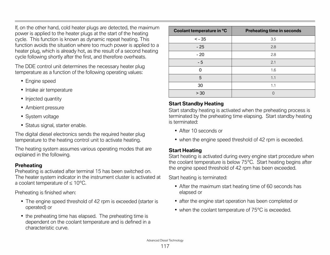
Advanced Diesel Technology
117
If, on the other hand, cold heater plugs are detected, the maximumpower is applied to the heater plugs at the start of the heatingcycle. This function is known as dynamic repeat heating. Thisfunction avoids the situation where too much power is applied to aheater plug, which is already hot, as the result of a second heatingcycle following shortly after the first, and therefore overheats.
The DDE control unit determines the necessary heater plugtemperature as a function of the following operating values:
• Engine speed
• Intake air temperature
• Injected quantity
• Ambient pressure
• System voltage
• Status signal, starter enable.
The digital diesel electronics sends the required heater plugtemperature to the heating control unit to activate heating.
The heating system assumes various operating modes that areexplained in the following.
PreheatingPreheating is activated after terminal 15 has been switched on.The heater system indicator in the instrument cluster is activated ata coolant temperature of ≤ 10°C.
Preheating is finished when:
• The engine speed threshold of 42 rpm is exceeded (starter isoperated) or
• the preheating time has elapsed. The preheating time isdependent on the coolant temperature and is defined in acharacteristic curve.
Start Standby HeatingStart standby heating is activated when the preheating process isterminated by the preheating time elapsing. Start standby heatingis terminated:
• After 10 seconds or
• when the engine speed threshold of 42 rpm is exceeded.
Start HeatingStart heating is activated during every engine start procedure whenthe coolant temperature is below 75°C. Start heating begins afterthe engine speed threshold of 42 rpm has been exceeded.
Start heating is terminated:
• After the maximum start heating time of 60 seconds haselapsed or
• after the engine start operation has been completed or
• when the coolant temperature of 75°C is exceeded.
Coolant temperature in °C Preheating time in seconds
< - 35 3.5
- 25 2.8
- 20 2.8
- 5 2.1
0 1.6
5 1.1
30 1.1
> 30 0

118Advanced Diesel Technology
Emergency HeatingEmergency heating is triggered for 3 minutes in the event ofcommunication between the DDE control unit and heating controlunit failing for more than 1 second.
The heating control unit then uses safe values so as to preventdamage to the heating system.
Concealed HeatingPreheating and start standby heating are activated as so-calledconcealed heating up to a coolant temperature of 30°C.
Concealed heating is triggered a maximum of 4 times and is thennot enabled again before the engine is restarted.
Concealed heating is triggered by the following signals:
• Driver's seat occupancy
• Driver's seat belt buckle
• Valid key
• Terminal R
• Clutch operated.
Partial Load HeatingPartial load heating can occur at coolant temperatures below 75°Cafter starting the engine. Actuation of the heater plugs depends onthe engine speed and load, thus improving the exhaust gas charac-teristics.
Actuation and Fault DetectionThe power output stages for heater plug actuation are located inthe heater control unit. The heater control unit does not have itsown fault code memory. Faults in the heating system detected bythe heater control unit are signalled via the LIN-bus to the digitaldiesel electronics.
The corresponding fault codes are then stored in the DDE faultcode memory.
To avoid damage, the heater control unit shuts down all heatingactivities when the permissible operating temperature of the heatercontrol unit is exceeded.
The ceramic heater plugs are designed for an operating voltage of7.0 to 10.0 V. A voltage of 10 V can be applied to heat up the plugat a faster rate during the heating process. A PWM signal isapplied to the heater plugs for the purpose of maintaining theheater plug temperature.
Consequently, an effective voltage is established at the heaterplugs that is lower than the system voltage.
Note: The ceramic heater plugs are susceptible to impactand bending loads. Heater plugs that have beendroppedmay be damaged.
Note: A maximum voltage of 7 Vmay be applied to theheater plugs when removed. Higher voltageswithout cooling air movement can irreparablydamage the heater plugs.

Advanced Diesel Technology
119
NOTESPAGE