ST300 SR-400 SR-50 - Telex · fig ure 3 op er at ing fea tures sr-400-5-set e.d.r. volume off/on...
22
Telex Operating Instructions ST300 Transmitter SR-400 17 Channel Receiver SR-50 Single Channel Receiver
Transcript of ST300 SR-400 SR-50 - Telex · fig ure 3 op er at ing fea tures sr-400-5-set e.d.r. volume off/on...
TelexOp er at ing In struc tions
ST300 Transmitter
SR-400 17 Channel Receiver
SR-50 Single Channel Receiver

INTRODUCTIONWHAT IS THE TELEX SOUNDENHANCEMENT SYSTEM?
Trans mit ter: The trans mit ter gen er ates and am pli -fies a RF (Ra dio Fre quency) car rier sig nal, mod u -lates this car rier with the mi cro phone sig nal, andra di ates the mod u lated RF car rier.
Re ceiver: The FM VHF re ceiver is tuned to the fre -quency of the trans mit ter. The re ceiver picks up thera di ated RF sig nal from the trans mit ter through thean tenna and con verts the RF sig nal into au dio volt -ages for use with an ear phone, head phone, but tonre ceiver, neckloop, etc. The re ceiver fre quency must be matched to the trans mit ter fre quency.
WHAT FREQUENCY BAND DOES THETELEX SYSTEM OPERATE IN?
The Telex Sys tems fea ture a syn the sized trans mit terand sin gle chan nel or syn the sized re ceiv ers op er at -ing in the VHF Band be tween 72-76 MHz. See Ta -ble 1 for stan dard fre quen cies avail able.
Each trans mit ter chan nel can be uti lized by anynum ber of re ceiv ers in any given area. Up to eightsi mul ta neous sys tems can be used, and with properplace ment of ad ja cent chan nels, up to ten sys temscan be used.
-1-
SOUNDSOURCE TRANSMITTER
ANT. ANT.
RF CARRIERSIGNAL
FMRECEIVER EARPHONE
Fig ure 1Block Di a gram of Typ i cal Sound En hance ment Sys tem
OFTEN ASKED QUESTIONS
Ques tion: Can more than one sys tem be used si -mul ta neously?
An swer: Yes but never on the same fre quency.You will need to have dif fer ent fre quen cies for ev -ery re ceiver/trans mit ter com bi na tion. All trans mit -ters are fac tory set for spe cific fre quen cies.
Ques tion: Is the sys tem more sen si tive in any onepar tic u lar di rec tion?
An swer: No, the trans mit ter’s an tenna ra di atesequally in all di rec tions, but the sig nal is at ten u atedby your body, walls or other sur round ing ob jects.The re ceiv ing an tenna is es sen tially sen si tive in alldi rec tions as well.
Ques tion: Can the re ceiver re ceive other trans mis -sions when the trans mit ter is turned off?
An swer: Yes it can. Telex sys tems op er ate in theVHF Band be tween 72-76 MHz. How ever, it is notsus cep ti ble to ra dio wave skip, CB’ers or stan dardFM ra dio trans mis sions.
The fre quency your sys tem op er ates on is com puterse lected for least in ter fer ence, but there is no suchthing as a 100% clear chan nel all the time, any -where in the U.S.A., for ever!
If the sys tem is go ing to be used in a per ma nentfixed lo ca tion, it should op er ate in ter fer ence free un -til such a time or date when some one else be ginsus ing the same fre quency.
If the sys tem is go ing to be mov ing among var i ouslo ca tions, you may run into oc ca sional fre quency con flicts.
When ever the sys tem is in use, the trans mit tershould be left on to pre vent the re ceiver from pick -ing up out side in ter fer ence.
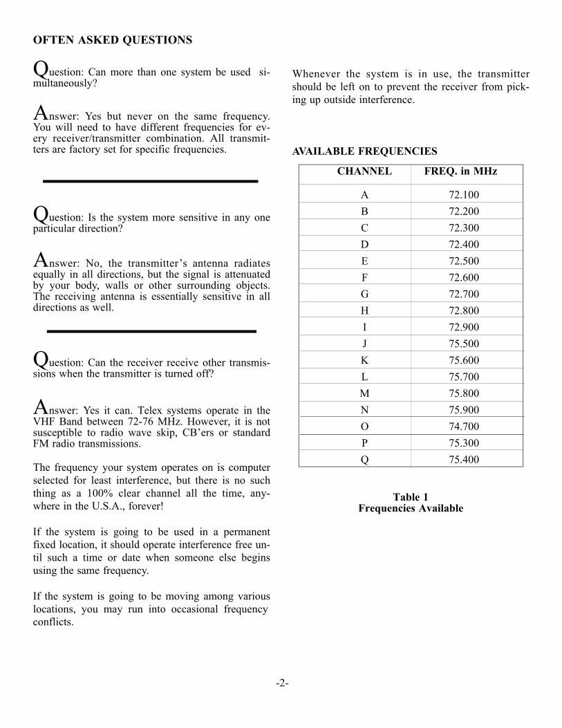
AVAIL ABLE FRE QUEN CIES
Ta ble 1Fre quen cies Avail able
-2-
CHAN NEL FREQ. in MHz
A 72.100B 72.200C 72.300D 72.400E 72.500F 72.600G 72.700H 72.800I 72.900J 75.500K 75.600L 75.700M 75.800N 75.900O 74.700P 75.300Q 75.400

TECHNICAL INFORMATION
SR-50 RECEIVER
GENERAL DESCRIPTION SR-50
The Telex SR-50 Re ceiver is a com po nent of a sys -tem which op er ates on 17 fac tory pre set chan nels inthe 72 to 76 MHz fre quency band. The re ceiv ers are de signed to be used with Telex ST-300 and PST-170 trans mit ters, but they can be used with other brandsof trans mit ters in the 72 to 76 MHz band pro videdthe fre quen cies match.
OPERATING FEATURES
Vol ume OFF/ON Con trol: The thumbwheel con -trol serves as both an off/on switch and as a vol ume con trol.
Fig ure 2Op er at ing Fea tures SR-50
The re ceiver is turned off when the con trol is in theex treme coun ter clock wise po si tion, when viewedfrom the rear and the vol ume is loud est when thecon trol is in the ex treme clock wise po si tion.
Head phone Jack: The re ceiver jack ac cepts a0.140-inch (3.5 mm) di am e ter min ia ture phone plug. A va ri ety of ac ces sory units can be plugged into thejack for re cep tion of the de sired chan nels be ingtrans mit ted.
Belt Clip: The belt clip sup plied is de tach able byspread ing the wire apart at the tops and re mov ingone side of the clip form the case and then the other.
-3-
Telex
VOLUME OFF/ON CONTROL
HEADPHONE JACK
CHANNELA
R
BELT CLIP
BATTERYORIENTATION
BATTERY COMPARTMENT COVER
BELT CLIPBELT CLIPBELT CLIP

SR-400 SYNTHESIZEDRECEIVER
General Description SR-400
The Telex SR-400 Re ceiver is a com po nent of asys tem which op er ates on sev en teen user selectablechan nels in the 72 to 76 MHz fre quency band. There ceiv ers are de signed to be used with the TelexST-300 and PST-170 Trans mit ters.
Operating Features
Vol ume OFF/ON Con trol: This thumbwheel con -trol serves as both an off/on switch and as a vol ume con trol. The re ceiver is turned off when the con trolis in the ex treme coun ter-clock wise po si tion, whenviewed from the rear, and the vol ume is loud estwhen the con trol is in the ex treme clock wise po si -tion.
Tre ble Con trol: A push but ton tre ble con trol is pro -vided to en hance higher fre quency au dio when thebut ton is en gaged, in di cated by .
Head phone Jack: The re ceiver jack ac cepts a0.140-inch (3.5 mm) di am e ter min ia ture plug. A va -ri ety of ac ces sory units can be plugged into this jack for lis ten ing.
Belt Clip: The belt clip sup plied is de tach able byspread ing the wire apart at the tops and re mov ingone side of the clip form the case and then the other.
-4-
SPEC I FI CA TIONS
SR-50 Sin gle Chan nel Re ceiverTem per a ture Range .....................................................................................................0 to +50 de grees CSup ply Volt age ...............................................................................................2-3 Volts, (2) AA Bat teriesBat tery Life ..............................................................................................................20-30 Hrs - Al ka line
8-10 Hrs - NicadSen si tiv ity (12 dB SINAD @ 25 kHz de vi a tion) ...................................0.5µ V typ i cal/1µ V max i mumDis tor tion ...............................................................................................................................less than 2%Fre quency Re sponse - 100 Hz-10 kHz .............................................................Less than 3 dB Vari a tionAu dio Out put @ 10% Dis tor tion
Con trols and Con nec tions ................................................................................Vol ume OFF/ON Switch,Au dio Out put Jack
8 ohm
50 mW
3.0V
15 mW
10 mW
Bat tery In putVolt age
32 ohm
80 mW
2.0V
NOTE: A head phone or other de vice must beplugged in the head phone jack in or der to turn onthe SR-400. This is to pre vent drain ing the bat ter iesif the switch is ac ci dently left on.

Fig ure 3Op er at ing Fea tures SR-400
-5-
SET
E.D.R.
VOLUME OFF/ON CONTROL
HEADPHONE JACK
SETSWITCHBUTTON
TREBLE CONTROLBELT CLIP
BATTERYCOMPARTMENT
TelexSR-400
P/N:71166000FCC ID: B5DE405
S/N:00001
SPEC I FI CA TIONS
SR-400 17 Chan nel Syn the sized Re ceiverTem per a ture Range .....................................................................................................0 to +50 de grees CSup ply Volt age ...............................................................................................2-3 Volts, (2) AA Bat teriesBat tery Life ..............................................................................................................16-20 Hrs - Al ka line
12-16 Hrs - Nickel Metal Hy dride8-10 Hrs - Nickel-cad mium
Fre quency Re sponse ....................................................................................................100-10 kHz ±3 dBSen si tiv ity (12 dB SINAD @ 74 MHz)...................................................................................1µ V max.Dis tor tion ...............................................................................................................................less than 2%Au dio Out put @ 10% Dis tor tion
Con trols and Con nec tions.................................................................................Vol ume OFF/ON Switch;Tre ble Con trol Switch; Chan nel Se lec tion Switch
Au dio Out put Jack
2.0 V
50 mW
32 ohm8 ohm
15 mW
80 mW
Bat tery In putVolt age
3.0 V
10 mW
ST-300 SYNTHESIZED TRANSMITTER
General Description
The Telex ST-300 is a base sta tion trans mit ter which op er ates in the 72-76 MHz band and ac cepts a widerange of au dio in put lev els.
Operating Features
-6-
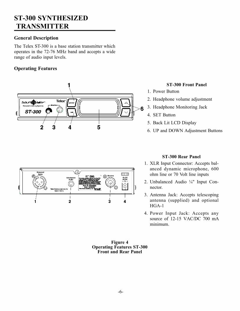
ST-300 Front Panel1. Power But ton
2. Head phone vol ume ad just ment
3. Head phone Mon i tor ing Jack
4. SET But ton
5. Back Lit LCD Dis play
6. UP and DOWN Ad just ment But tons
ST-300 Rear Panel1. XLR In put Con nec tor: Ac cepts bal -
anced dy namic mi cro phone, 600ohm line or 70 Volt line in puts
2. Un bal anced Au dio ¼" In put Con -nec tor.
3. An tenna Jack: Ac cepts tele scop ingan tenna (sup plied) and op tionalHGA-1
4. Power In put Jack: Ac cepts anysource of 12-15 VAC/DC 700 mAmin i mum.
Fig ure 4Op er ating Fea tures ST-300
Front and Rear Panel
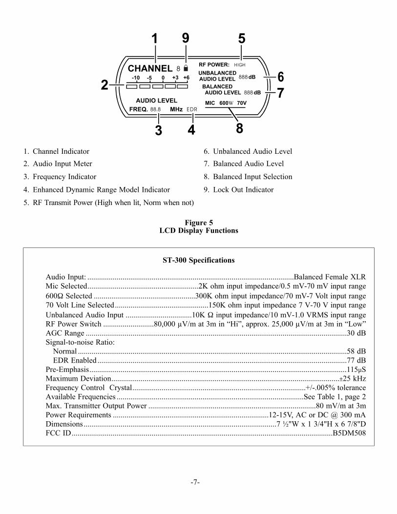
Fig ure 5LCD Dis play Func tions
-7-
1. Chan nel In di ca tor
2. Au dio In put Me ter
3. Fre quency In di ca tor
4. En hanced Dy namic Range Model In di ca tor
5. RF Trans mit Power (High when lit, Norm when not)
6. Un bal anced Au dio Level
7. Bal anced Au dio Level
8. Bal anced In put Se lec tion
9. Lock Out In di ca tor
CHANNEL-10 -5 0 +3 +6
AUDIO LEVELFREQ. 88.8 MHz EDR
RF POWER: HIGH
UNBALANCEDAUDIO LEVEL
BALANCED AUDIO LEVEL dB888
888 Bd
MIC 600 70VW
8
1
2
3 4
5
67
8
9
ST-300 Spec i fi ca tions
Au dio In put: ..........................................................................................................Bal anced Fe male XLRMic Se lected.........................................................2K ohm in put im ped ance/0.5 mV-70 mV in put range600Ω Se lected ....................................................300K ohm in put im ped ance/70 mV-7 Volt in put range70 Volt Line Se lected................................................150K ohm in put im ped ance 7 V-70 V in put rangeUn bal anced Au dio In put ..................................10K Ω in put im ped ance/10 mV-1.0 VRMS in put rangeRF Power Switch ..........................80,000 µV/m at 3m in “Hi”, approx. 25,000 µV/m at 3m in “Low”AGC Range ......................................................................................................................................30 dBSig nal-to-noise Ra tio:
Nor mal ..........................................................................................................................................58 dBEDR En abled ................................................................................................................................77 dB
Pre-Em pha sis....................................................................................................................................115µSMax i mum De vi a tion.....................................................................................................................±25 kHzFre quency Con trol Crys tal.........................................................................................+/-.005% tol er anceAvail able Fre quen cies ................................................................................................See Ta ble 1, page 2Max. Trans mit ter Out put Power ......................................................................................80 mV/m at 3mPower Re quire ments ................................................................................12-15V, AC or DC @ 300 mADi men sions...................................................................................................7 ½"W x 1 3/4"H x 6 7/8"DFCC ID......................................................................................................................................B5DM508
EQUIP MENT SET-UP
ST-300 Synthesized TransmitterUN PACKING: Un pack your sound en hance mentsys tem. If there are any dam ages or short ages, re ferto the "War ranty Ser vice In for ma tion."
ST-300 TRANS MITTER LO CA TION: Se lect asuit able lo ca tion for the ST-300 Trans mit ter. Try tokeep a clear, un ob structed path be tween the trans -mit ter and re ceiver and al low plenty of free spacearound the trans mit ter an tenna.
AN TENNA CON NEC TIONS: Con nect the tele -scop ing an tenna to the rear panel AN TENNA jack.
For best re sults, the an tenna should be ver ti callyaligned. Tighten the knurled ring to hold the an tenna in place, and ex tend the an tenna to full length.
Fig ure 6An tenna Connection
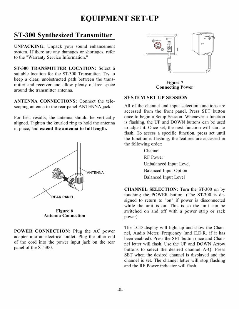
POWER CON NEC TION: Plug the AC poweradapter into an elec tri cal out let. Plug the other endof the cord into the power in put jack on the rearpanel of the ST-300.
Fig ure 7Con necting Power
SYSTEM SET UP SESSION
All of the chan nel and in put se lec tion func tions areac cessed from the front panel. Press SET but tononce to be gin a Setup Ses sion. When ever a func tion is flash ing, the UP and DOWN but tons can be usedto ad just it. Once set, the next func tion will start toflash. To ac cess a spe cific func tion, press set un tilthe func tion is flash ing, the fea tures are ac cessed inthe fol low ing or der:
Chan nelRF PowerUn bal anced In put LevelBal anced In put Op tionBal anced In put Level
CHAN NEL SE LEC TION: Turn the ST-300 on bytouch ing the POWER but ton. (The ST-300 is de -signed to re turn to "on" if power is dis con nectedwhile the unit is on. This is so the unit can beswitched on and off with a power strip or rackpower).
The LCD dis play will light up and show the Chan -nel, Au dio Me ter, Fre quency (and E.D.R. if it hasbeen en abled). Press the SET but ton once and Chan -nel let ter will flash. Use the UP and DOWN Ar rowbut tons to se lect the de sired chan nel A-Q. PressSET when the de sired chan nel is dis played and thechan nel is set. The chan nel let ter will stop flash ingand the RF Power in di ca tor will flash.
-8-
Antenna12-15VAC/DC
+ -
REAR PANEL
ANTENNA

RF POWER SE LEC TION: While the RF Powerin di ca tor is flash ing, press the UP AR ROW forHIGH and DOWN for NORM (the RF Power linewill not be dis played). NORM power should beused for small to me dium sized ven ues and when -ever mul ti ple sys tems are be ing used. Press SETwhen the power is set and the Un bal anced In putlevel will flash.
UN BAL ANCED IN PUT LEVELAD JUST MENT: If the un bal anced au dio in put will not be used, with the Un bal anced In put Level flash -ing use the UP but ton to set the level to OFF andpress set to go to Bal ance In put Se lec tion.
If the Un bal anced in put will be used, con nect the in -put now and ap ply au dio con tent. With the au diocon tent play ing and Un bal anced In put level flash -ing, watch the au dio me ter. The peak sig nal shouldnot go above the 0 dB seg ment, use the UP andDOWN but tons to ad just the in put level so that theloud est in put lights up the 0 dB seg ment. When thelevel is set, press the SET but ton and one of theBal anced In put Op tions will flash (de fault is 70V).
BAL ANCED IN PUT SE LEC TION: If the bal -anced au dio in put will not be used, with one of theBal ance In put Op tions flash ing press SET so theBal anced In put Level is flash ing. Use the UP andDOWN but tons to set the level to OFF and pressSET to end the setup ses sion.
If the Bal anced in put will be used, with one of theop tions flash ing use the UP and DOWN but tons tose lect the cor rect in put. With the cor rect in put dis -played, press SET and the Bal anced In put Level in -di ca tor will flash.
CAU TION: Per ma nent dam age can re sult if 70Vline is used with the In put Se lec tion im prop erly set.
BAL ANCED IN PUT LEVEL AD JUST MENT:Make sure the Bal anced In put Se lec tion is set cor -rectly, then con nect the in put and ap ply au dio con -tent. With the au dio con tent play ing and Bal ancedIn put level flash ing, watch the au dio me ter. Thepeak sig nal should not go above the 0 dB seg ment,use the UP and DOWN but tons to ad just the in putlevel so that the loud est in put lights up the 0 dBseg ment. When the level is set, press the SET but ton and the Setup Ses sion will end.
En hanced Dy namic Range (E.D.R.) Op er a tion
The Telex ST-300 Trans mit ter is equipped withE.D.R., En hanced Dy namic Range (companded) au -dio. This mode greatly im proves the Au dio Sig nal to Noise Ra tio when used with the Telex ModelSR-400 re ceiver. The E.D.R. mode must be se lected on both the trans mit ter and re ceiver to be ef fec tive.
1. To en gage the E.D.R. func tion, turn the ST-300off with the power switch.
2. Press and hold the SET but ton while you turn the ST-300 back on. The E.D.R. sym bol will be dis -played in the lower right cor ner to in di cate themode is ac tive.
3. Re peat the pro ce dure to dis able the E.D.R func tion.
Change Lock Out
The ST-300 SET but ton can be locked to pre ventE.D.R. ac ti va tion, and un in tended chan nel changes.
1. To en gage the Lock Out Fea ture, press the UPand DOWN but tons at the same time and holdthem down for 10 sec onds.
2. The pad lock sym bol will ap pear and the set but -ton is dis abled.
3. To un lock the sys tem, press the Up and DOWNbut tons and hold them for 10 sec onds or un til the pad lock sym bol dis ap pears.
AU DIO MON I TOR: Turn the Mon i tor (vol ume)con trol all the way down (coun ter clock wise). Af terthe au dio in put lev els have been ad justed, Ste reohead phones with a ¼ in. plug can be plugged intothe Mon i tor jack. If you wish to mon i tor the au diopro gram ma te rial, turn up the mon i tor (vol ume) con -trol to the de sired level. The mon i tor con trol doesnot af fect the trans mit ted au dio level.
-9-

MUL TI PLE SYS TEM IN STAL LA TIONS: Aswith any ra dio de vice, in ter fer ence can oc cur at anytime. The fre quen cies of fered are shared with otherle git i mate us ers. The se ver ity of in ter fer ence var ieswith the dis tance to the in ter fer ing sta tion. Mul ti plesys tems fur ther com pli cate in stal la tions. The fol low -ing steps are sug gested in or der to achieve best re -sults in your in stal la tion.
1. In or der to de ter mine whether your se lected fre -quen cies have min i mum in ter fer ence, Telex rec -om mends that you first tem po rarily in stall there ceiv ers in your pro posed set ting and mon i torthe chan nel for in ter fer ence. To do this (withfresh bat ter ies in stalled) turn on your re ceiver,but DO NOT turn on any other re ceiver or trans -mit ter at this time. If audible in ter fer ence is pres -ent, this may in di cat e an other user on thechan nel. Mon i tor ing should be re peated for eachchan nel that you pro pose to use. DO NOT usechan nels that have in ter fer ence.
2. Set your trans mit ter(s) to chan nels with no ormin i mum in ter fer ence. Each trans mit ter must beset to a sep a rate fre quency. For best re sults whenus ing mul ti ple trans mit ters, each trans mit tershould be in stalled sep a rately as far as pos si blefrom the oth ers.
3. Turn on the trans mit ter(s) with an ac tive au dioin put. Test walk a re ceiver through the ex pectedlis ten ing area to ver ify cov er age. The sys temshould now be ready for use.
-10-
Prob lem So lu tionTrans mis sion sounds com pressed on SR-50 orSR-400
E.D.R. func tion may be en gaged on the ST-300. See set ting E.D.R. func tion on page 9. TheE.D.R. fea ture can only be used with theSR-400 and must be ac tive on both trans mit terand re ceiver to be ef fec tive.
SET but ton does not work, can not changechannel
Lock Out is en gaged, press and hold UP andDOWN but tons un til the pad lock sym bol dis ap -pears.
EQUIPMENT OPERATIONSR-50 SYNTHESIZEDRECEIVER
Operation of the SR-50 Receiver
Try to keep a clear, un ob structed path be tween thetrans mit ter and re ceiver an ten nas for clear re cep tion.
Plug in a unit such as an ear phone, head phone but -ton re ceiver, in duc tion coil neckloop, or au dio-inputhear ing aid into the head phone jack. (The cord actsas a re ceiv ing an tenna.)
Ro tate the VOL UME OFF/ON con trol slowly in the clock wise di rec tion while mon i tor ing the vol umelevel.
When sat is fied with the vol ume level, place the Re -ceiver in a pocket or clip it to your belt for con ve -nience.
Al ways re turn the VOL UME OFF/ON con trol to the OFF po si tion when the re ceiver is not in use to pre -serve bat tery life and pre vent bat tery leak age.
SR-400 SYNTHESIZEDRECEIVER
Operation of the SR-400 Receiver
Try to keep a clear, un ob structed path be tween thetrans mit ter and re ceiver an ten nas for a clear trans -mis sion.
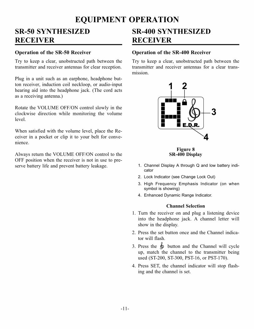
Fig ure 8SR-400 Display
1. Chan nel Dis play A through Q and low bat tery in di -ca tor
2. Lock In di ca tor (see Change Lock Out)
3. High Fre quency Em pha sis In di ca tor (on whensym bol is show ing)
4. En hanced Dy namic Range In di ca tor.
Chan nel Se lec tion1. Turn the re ceiver on and plug a lis ten ing de vice
into the head phone jack. A chan nel let ter willshow in the dis play.
2. Press the set but ton once and the Chan nel in di ca -tor will flash.
3. Press the but ton and the Chan nel will cy cleup, match the chan nel to the trans mit ter be ingused (ST-200, ST-300, PST-16, or PST-170).
4. Press SET, the chan nel in di ca tor will stop flash -ing and the chan nel is set.
-11-
E.D.R.
2
E.D.R.
4
1
3

En hanced Dy namic Range (E.D.R.) Op er a tion
The Telex ST-300 and PST-170 Trans mit ters areequipped with E.D.R., En hanced Dy namic Range(companded) au dio. This mode greatly im proves the Au dio Sig nal to Noise Ra tio when used with theTelex Model SR-400 re ceiver. The E.D.R. modemust be se lected on both the trans mit ter and re -ceiver to be ef fec tive.
1. To en gage the E.D.R func tion turn the SR-400off with the vol ume con trol thumb wheel.
2. Press and hold the SET but ton while you turn the SR-400 back on. The E.D.R. sym bol will be dis -played in the lower right cor ner to in di cate themode is ac tive.
3. Re peat the pro ce dure to dis able the E.D.R. func -tion.
Change Lock Out
The SR-400 SET but ton can be locked to pre ventE.D.R. ac ti va tion, and un in tended chan nel changes.The High Fre quency Em pha sis but ton will re mainac tive at all times for the con ve nience of the user.
1. To en gage the Lock Out Fea ture, press the SETand but tons at the same time and hold themdown for 10 seconds.
2. The pad lock symbol will ap pear and the set but -ton is dis abled.
3. To un lock the sys tem, press the SET and but -tons and hold them for 10 sec onds or un til thepad lock symbol dis ap pears.
Low Bat tery In di ca tion1. When there is ap prox i mately 10% of the bat tery
life left, a bat tery sym bol will flash al ter natelywith the chan nel let ter in the LCD dis play.
2. When there is only 5% bat tery life left, the bat -tery sym bol will con stantly flash in the dis play.
Low Bat tery Dis play
-12-
E.D.R.E.D.R.

BATTERY REPLACEMENT
The SR-50 and SR-400 Re ceivers use two (2) AAbat ter ies. When the bat ter ies are low the sound willbe dis torted. Re place weak bat ter ies with two freshAA bat ter ies, and po si tion them in the bat tery com -part ment as il lus trated in Fig ure 9.
For ad di tional in for ma tion re fer to the “Bat tery In -for ma tion” Sec tion.
NOTE: If the unit is to be stored for any length oftime make sure you re move the bat ter ies from theunit.
Fig ure 9Bat tery In stal la tion - SR-50 and SR-400
-13-
BELT CLIP
BATTERYORIENTATION
BATTERY COMPARTMENT COVER
BELT CLIPBELT CLIPBELT CLIP
BATTERY INFORMATIONGeneral
Im proper bat tery se lec tion, use, in stal la tion and care are the cause of nu mer ous wire less sys tem fail ures.
Alkaline Batteries
Al ka line bat ter ies such as Mallory’s DURACELL®or Eveready’s EN ER GIZER® pro vide the most re li -able op er a tion in wire less trans mit ters and re ceiv ers. The use of low cost car bon-zinc bat ter ies is NOTREC OM MENDED.
*EN ER GIZER® is a reg is tered trade mark of Un ionCar bide Cor po ra tion. *DURACELL® is a reg is tered trade mark ofDuracell Inc.
ANTENNA INFORMATION
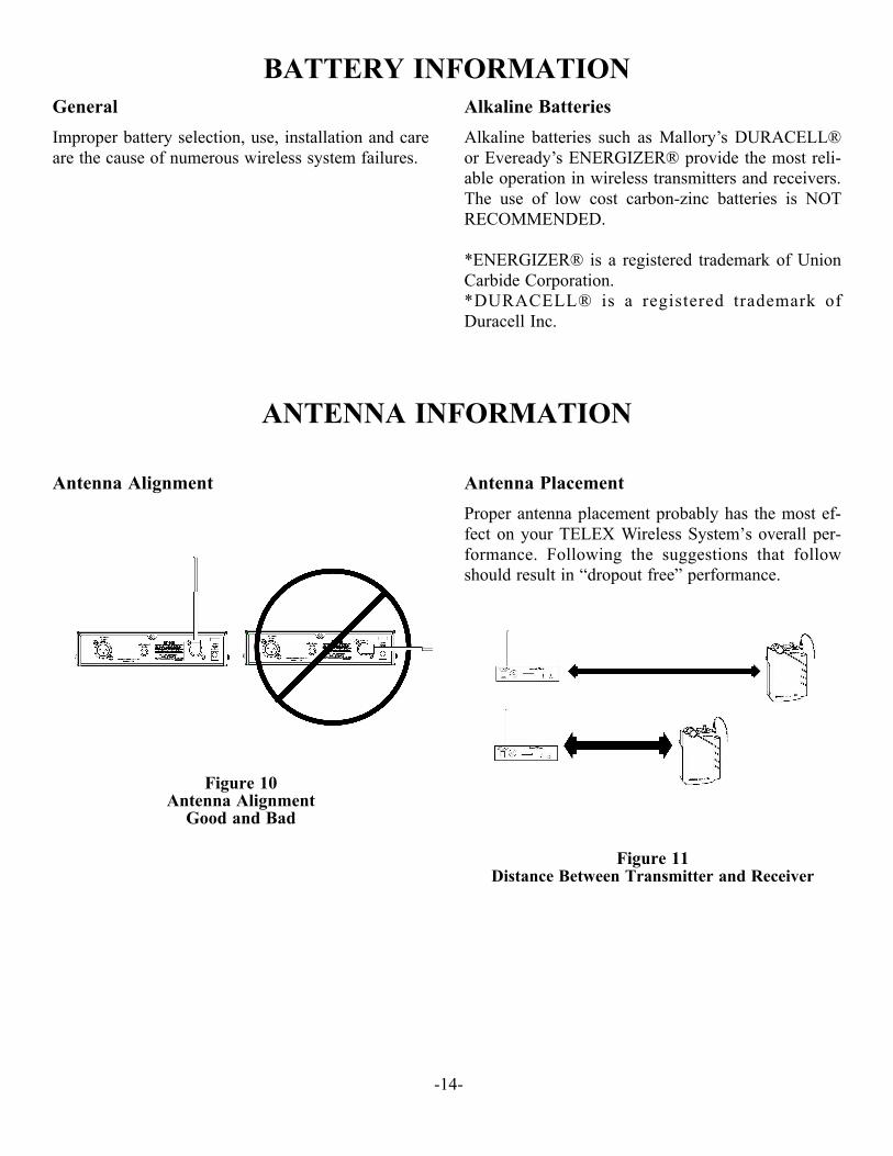
Antenna Alignment
Fig ure 10An tenna Align ment
Good and Bad
Antenna Placement
Proper an tenna place ment prob a bly has the most ef -fect on your TELEX Wire less Sys tem’s over all per -for mance. Fol low ing the sug ges tions that fol lowshould re sult in “drop out free” per for mance.
Fig ure 11Dis tance Be tween Trans mit ter and Re ceiver
-14-

-----Keep the dis tance be tween the trans mit ter andthe re ceiver(s) as short as pos si ble. The greater thedis tance the weaker the sig nal.
Make sure the “sig nal path” be tween the trans mit terand re ceiver(s) is un ob structed. You should al waysbe able to vi su ally lo cate the an tenna of the trans -mit ter at all times.
SIG NAL REACHES AN TENNA AT FULL STRENGTH WITH NO OB -STRUC TIONS.
Fig ure 12Keeping Site Clear to An tenna
At tempting to op er ate the sound en hance ment sys -tem through or around walls, ceil ings, metal ob jects, etc., will re duce sys tem range and per for mance.
SIG NAL RE FLEC TION OFF A METAL OB STRUC TION CAUSES RE DUCED SIG NAL AND “MULTIPATH”
Fig ure 13Op er ating Through Ob struc tion
DO NOT - Mount the trans mit ter on, or next to,metal such as beams, walls with metal studs, etc.This will “de tune” the trans mit ter an tenna whichcan re sult in loss of sig nal at the re ceiver.
Fig ure 14Trans mit ter An tenna Place ment
set
power
Monitor
Telex
ST-300
set
power
Monitor
Telex
ST-300
LOCATION IS OK
LOCATION IS BAD
-15-
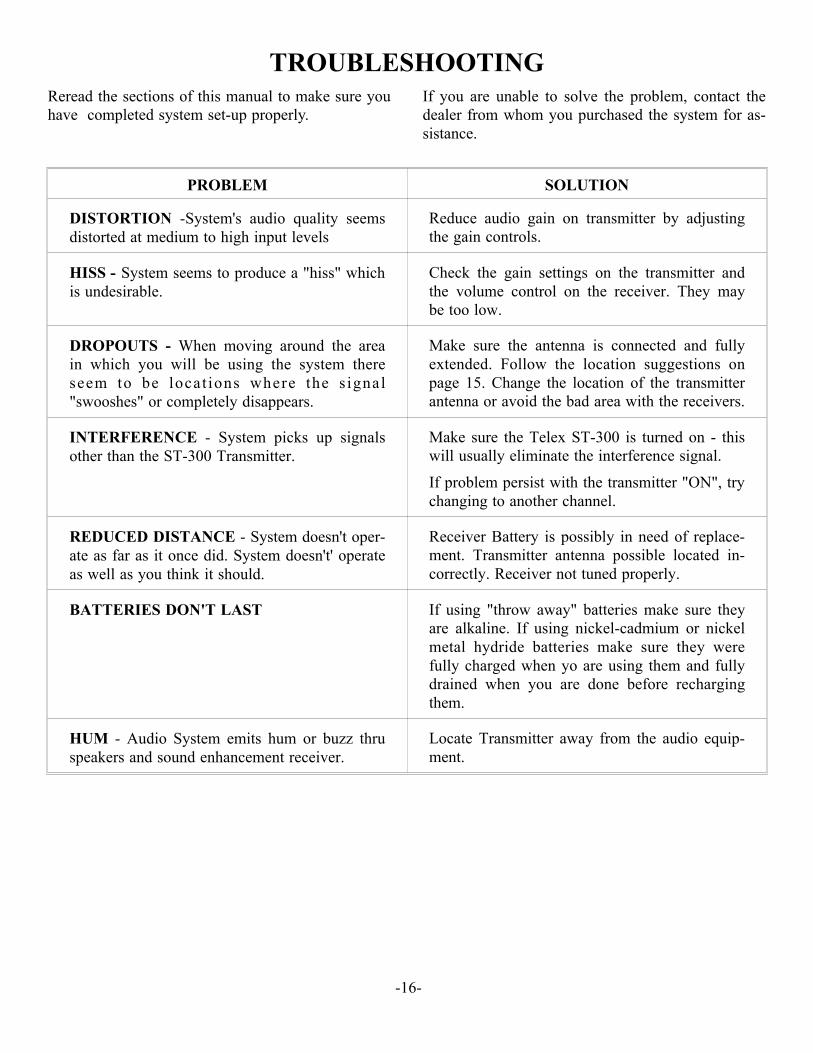
TROUBLESHOOTINGRe read the sec tions of this man ual to make sure you have com pleted sys tem set-up prop erly.
If you are un able to solve the prob lem, con tact thedealer from whom you pur chased the sys tem for as -sis tance.
-16-
PROB LEM SO LU TION
DIS TOR TION -Sys tem's au dio qual ity seemsdis torted at me dium to high in put lev els
Re duce au dio gain on trans mit ter by ad just ingthe gain con trols.
HISS - Sys tem seems to pro duce a "hiss" which is un de sir able.
Check the gain set tings on the trans mit ter andthe vol ume con trol on the re ceiver. They maybe too low.
DROP OUTS - When mov ing around the areain which you will be us ing the sys tem thereseem to be lo ca t ions where the s ig nal"swooshes" or com pletely dis ap pears.
Make sure the an tenna is con nected and fullyex tended. Fol low the lo ca tion sug ges tions onpage 15. Change the lo ca tion of the trans mit teran tenna or avoid the bad area with the re ceiv ers.
IN TER FER ENCE - Sys tem picks up sig nalsother than the ST-300 Trans mit ter.
Make sure the Telex ST-300 is turned on - thiswill usu ally elim i nate the in ter fer ence sig nal.
If prob lem per sist with the trans mit ter "ON", try chang ing to an other chan nel.
RE DUCED DIS TANCE - Sys tem does n't op er -ate as far as it once did. Sys tem does n't' op er ateas well as you think it should.
Re ceiver Bat tery is pos si bly in need of re place -ment. Trans mit ter an tenna pos si ble lo cated in -cor rectly. Re ceiver not tuned prop erly.
BAT TER IES DON'T LAST If us ing "throw away" bat ter ies make sure theyare al ka line. If us ing nickel-cad mium or nickelmetal hy dride bat ter ies make sure they werefully charged when yo are us ing them and fullydrained when you are done be fore re charg ingthem.
HUM - Au dio Sys tem emits hum or buzz thruspeak ers and sound en hance ment re ceiver.
Lo cate Trans mit ter away from the au dio equip -ment.
-17-
CUSTOMER SERVICE INFORMATION
If your re ceiver or trans mit ter should need ser vic ing un der the war ranty, please con tact:
Customer Service DepartmentTELEX COMMUNICATIONS, INC.8601 East Cornhusker Highway,P.O. Box 5579,Lincoln, Nebraska 68505-5579 U.S.A. Phone: (402) 467-5321 or 465-7021
All claims of de fect or short age should be sent to the above ad dress. When re turn ing items forser vice, you must pro vide date and proof of pur chase, such as a copy of the sales re ceipt, to es -tab lish war ranty. A let ter should be in cluded out lin ing all symp toms and claimed de fects. In for -ma tion on how the equip ment was in stalled and used is very help ful. Please in clude your phone num ber and re turn ad dress in case our ser vice tech ni cians need to con tact you.
Units that have been mod i fied can not be ac cepted for re pair.
In clude all in for ma tion re quested by the Ser vice De part ment. Then pack the unit as fol lows:
Check the unit to see that all parts and screws are in place. Then wrap it in heavy pa per or putit in a plas tic bag. If the orig i nal car ton is not avail able, place the unit in a strong car ton that isat least six inches big ger in all three di men sions than the unit. Fill the car ton equally around the unit with re sil ient pack ing ma te rial (shred ded pa per, foam, etc.). Seal it with gummed pa pertape, tie it with a strong cord, and ship it by pre paid ex press, United Par cel Ser vice or in suredpar cel post to the Telex Ser vice De part ment.
It is very im por tant that the ship ment be well-packed and fully in sured. Dam age claims must be set tled be tween you and the car rier and this can de lay re pair and re turn of the unit to you.
Telex re serves the right to make changes in de sign and im prove ment on its prod uct with out as -sum ing any ob li ga tion to in stall the same on any of its prod ucts pre vi ously man u fac tured. Fur -ther Telex re serves the right to ship new and/or im proved prod ucts which are sim i lar to theform, fit and func tion of prod ucts orig i nally or dered.
ACCESSORIES and PARTS
Rack Mounting KitRM-S for mount ing one ST-300.............................................................................................71081-001RM-D for mount ing two ST-300’s .........................................................................................71081-002
Earphone (for SR-400 and SR-50)(sin gle) ...................................................................................................................................59840-005
Earphone (for SR-400 and SR-50)(dual) .......................................................................................................................................59840-001
Collapsible Lightweight Headphone(for SR-400 and SR-50)
(dual))......................................................................................................................................59840-007NL-4S
In duc tion Coil Neckloop..........................................................................................................71120001Antenna, Telescoping
for ST-300 .................................................................................................................................877960-1Belt Clip
for SR-50 and SR-400 .................................................................................................................358815Power Supply
for ST-300 ....................................................................................................................................730139
-18-
FCC INFORMATION
The Telex SR-50 Re ceiver, and SR-400 Re ceiver are au tho rized un der part 15 of the FCC Reg u la -tions. Changes or mod i fi ca tions to this equip ment could void the user’s au thor ity to op er ate theequip ment.
The Telex Model ST-300 Trans mit ter is au tho rized un der Fed eral Com mu ni ca tions Com mis sion andIn dus try Can ada Rules. Li cens ing of the Trans mit ter, if re quired, is the us ers re spon si bil ity andlicensability de pends upon the us ers clas si fi ca tion, and fre quency se lected.
CAU TION: Changes or mod i fi ca tions made by the user could void the user's au thor ity to op er ate the equip ment.
Op er a tion is sub ject to the fol low ing two con di tions: (1) This de vice may not cause in ter fer ence, and(2) This de vice must ac cept any in ter fer ence, in clud ing in ter fer ence that may cause un de sired op er a -tion of the de vice.


PN 804018 Rev. D SEPT 2005 Made in U.S.A.
TELEX COM MU NI CA TIONS, INC. 12000 Port land Ave. South, Bur nsville, MN 55337, U.S.A.


![[XLS]obcindia.co.inobcindia.co.in/obcnew/upload/obc/Unpaid Dividend 2013-14... · Web view400 400 400 400 400 400 400 400 400 400 400 400 400 400 400 400 400 400 400 400 400 400 400](https://static.fdocuments.us/doc/165x107/5aa6f94e7f8b9a54748b6a16/xls-dividend-2013-14web-view400-400-400-400-400-400-400-400-400-400-400-400.jpg)