St. Lucie Planti Unit ii Florida Power Light AFFILI*TION ...
26
ACC)ESSlON NBR FAC IL'0-335 AUTH. NAME NOODYz C. O. RECIP. NAME REQULATO INFORMATION DISTRIBUTION STEM (RIDS) 8712280186 DOC. DATE: 87/12/22 NOTARIZED: NO St. Lucie Planti Unit ii Florida Power h Light Co. AUTHOR AFFILI*TION Florida Power 5 Light Co. RECIPIENT AFFILI*TION Document Control Branch <Document Control Desk) DOCKET 05000335 SUBJECT: Responds to NRC 871125 request for addi info re proposed license amend. Proposed amend to permit replacement of spent fuel pool racks at Unit 1 to ensure that sufficient future capacity exists for storage of spent fuel. Figures encl. DISTRIBUTION CODE: A001D COPIES RECEIVED: LTR ~ ENCL j SIZE: TITLE: OR Submittal: General Distribution NOTES'ECIPIENT ID CODE/NAME PD2-2 LA TOURIQNYi E INTERNAL: ARM/DAF/LFMB NRR/DEST/CEB NRR/DEST/RSB * ILRB REQ FILE 01 EXTERNAL: LPDR NSIC COPIES LTTR ENCL 1 0 1 1 1 0 1 1 1 1 1 1 1 1 1 1 1 REC IP IENT ID CODE/NAME PD2-2 PD NRR/DEST/ADS NRR/DEST/MTB NRR/DOE*/TSB OQC/HDS2 RES/DE/EIB NRC PDR COPIES LTTR ENCL 5 5 1 1 1 1 1 1 1 0 1 1 1 1 TOTAL NUMBER OF COPIES REQUIRED: LTTR 20 ENCL 17
Transcript of St. Lucie Planti Unit ii Florida Power Light AFFILI*TION ...
ACC)ESSlON NBRFAC IL'0-335
AUTH. NAMENOODYz C. O.
RECIP. NAME
REQULATO INFORMATION DISTRIBUTION STEM (RIDS)
8712280186 DOC. DATE: 87/12/22 NOTARIZED: NOSt. Lucie Planti Unit ii Florida Power h Light Co.
AUTHOR AFFILI*TIONFlorida Power 5 Light Co.
RECIPIENT AFFILI*TIONDocument Control Branch <Document Control Desk)
DOCKET05000335
SUBJECT: Responds to NRC 871125 request for addi info re proposedlicense amend. Proposed amend to permit replacement of spentfuel pool racks at Unit 1 to ensure that sufficient futurecapacity exists for storage of spent fuel. Figures encl.
DISTRIBUTION CODE: A001D COPIES RECEIVED: LTR ~ ENCL j SIZE:TITLE: OR Submittal: General Distribution
NOTES'ECIPIENTID CODE/NAME
PD2-2 LATOURIQNYi E
INTERNAL: ARM/DAF/LFMBNRR/DEST/CEBNRR/DEST/RSB
* ILRBREQ FILE 01
EXTERNAL: LPDRNSIC
COPIESLTTR ENCL
1 01 1
1 01 1
1 11 1
1 1
1 1
1
REC IP IENTID CODE/NAME
PD2-2 PD
NRR/DEST/ADSNRR/DEST/MTBNRR/DOE*/TSBOQC/HDS2RES/DE/EIB
NRC PDR
COPIESLTTR ENCL
5 5
1 1
1 1
1 1
1 01 1
1 1
TOTAL NUMBER OF COPIES REQUIRED: LTTR 20 ENCL 17

~ ~
I
It r,y
tl
I
It

P. 0 x 14000, JUNO BEACH, FL 3340B.0420
g(ll/y
OECEft/GER 88 1987
L-87-538
U. S. Nuclear Regulatory CommissionAttn: Document Control DeskWashington, D.C. 20555
Gentlemen:
Re: St. Lucie Unit I
Docket No. 50-335S ent Fuel Rerack
By letter L-87-245, dated June l2, l987, Florida Power & Light Company (FPL)submitted a proposed license amendment to permit replacement of the spent fuelpool racks at St. Lucie Unit I to ensure that sufficient future capacity exists forstorage of spent fuel.
By letter dated November 25, I 987 (E. G. Tourigny to C. O. Woody) the NRC Staffrequested additional information in the area of plant systems it needed tocontinue its review of this proposed license amendment.
Attached is FPL's response to this request.
If additional information is required, please contact us.
Very truly yours,
~ ~. O. WooExecutiv ice President
COW/EJW/gp
Attachment
cc: Dr. J. Nelson Grace, Regional Administrator, Region II, USNRCSenior Resident Inspector, USNRC, St. Lucie Plant
'712280186= 871222 '.
PDR ADOCK 05OQO335t,' .. -. -..L„>DR
EJW4/054/ I
an FPL Group company

~ A
'I
il 0
t,
III
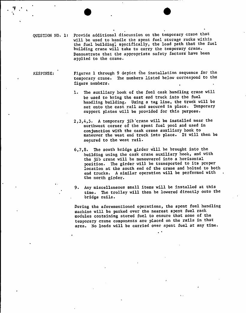
QUESTION NO. 1: Provide additional discussion on the temporary crane thatwill be used to handle the spent fuel storage racks withinthe fuel building", specifically, the load path that the fuelbuilding crane will take to carry the temporary crane.Demonstrate that the appropriate safety factors'ave beenapplied to the crane.
RESPONSE: Figures 1 through 9 depict the installation sequence for thetemporary crane. The numbers listed below correspond to thefigure numbers.
1. The auxiliary hook of the fuel cask handling crane willbe used to bring the east end truck into the fuelhandling building. Using a tag line, the truck will beset onto the east rail and secured in place. Temporarysupport plates will be provided for this purpose.
2,3,4,5. A temporary gib'crane will be installed near thenorthwest corner of the spent fuel pool and used inconjunction with the cask crane auxiliary hook tomaneuver the west end truck into place. It will then besecured to the west rail.
6,7,8. The south bridge girder will be brought into thebuilding using the cask crane auxiliary hook, and withthe jib crane will be maneuvered into a horizontalposition. The girder will be transported to its properlocation at the south end of the crane and bolted to bothend trucks. A similar operation will be performed withthe north girder.
9. Any miscellaneous small items will be installed at thistime. The trolley will then be lowered directly onto thebridge rails.
During the aforementioned operations, the spent fuel handlingmachine will be parked over the nearest spent fuel rackmodules containing stored fuel to ensure that none of thetemporary crane components are placed on the rails in thatarea. No loads will be carried over spent fuel at any time.

QUESTION No. 1 (continued)
RESPONSE: (continued)
The following safety factors, which meet or exceed therequirements of NUREG 0612, have been provided in the designof the load bearing components of the temporary crane:
Component Factor of safety** Criterion**
Bridge girdersEnd trucksWheels
Wheel bearingsDrum
Hoist rope
Hook
2.93
>202.50
3.34
5.34
Yield strengthUltimate strengthRated capacity*Rated capacity*Ultimate strength'-
Breaking strengthUltimate strength
* Rated capacity has a margin of 5 over ultimate strength.
** Factor of safety equals criterion stress over designstress.
The following steps are taken in the inspection and testingof the temporary crane to achieve compliance with the spiritof NUREG 0612.
a ~ The crane structural members are purchased to ASPIC
specification and certified as such.
b. The crane hoist is proof tested to 150X of the ratedload in the hoist manufacturer's shop.
C ~ The crane is erected in the crane manufacturer's shopand the workings of the trolley dri'ves and alignment ofthe trolly is confirmed.
d. All welds in the manufacturing of the crane are liquidpenetrant or magnetic particle tested.
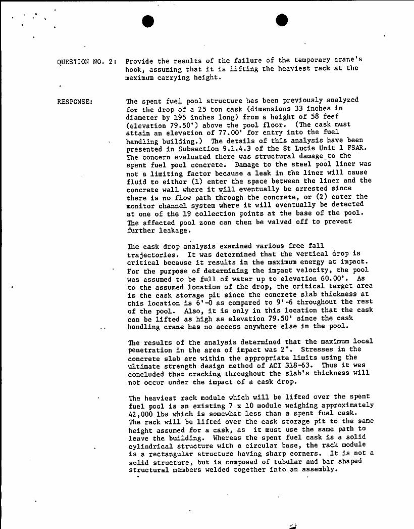
QUESTION NO. 2: Provide the results of the failure of the temporary crane'shook, assuming that it is lifting the heaviest rack at themaximum carrying height.
RESPONSE: The spent fuel pool structure has been previously analyzedfor the drop of a 25 ton cask (dimensions 33 inches indiameter by 195 inches long) from a height of 58 feet(elevation 79.50') above the pool floor. (The cask mustattain an elevation of 77.00'or entry into the fuelhandling building.) The details of this analysis have beenpresented in Subsection 9.1.4.3 of the St Lucie Unit 1 FSAR.
The concern evaluated there was structural damage to thespent fuel pool concrete. Damage to the steel pool liner was
not a limiting factor because a leak in the liner will causefluid to either (1) enter the space between the liner and theconcrete wall where it will eventually be arrested sincethere is no flow path through the concrete, or (2) enter themonitor channel system where it will eventually be detectedat one of the 19 collection points at the base of the pool.The affected pool zone can then be valved off to preventfurther leakage.
The cask drop analysis examined various free falltrajectories. It was determined that the vertical drop iscritical because it results in the maximum energy at impact.For the purpose of determining the impact velocity, the poolwas assumed to be full of water up to elevation 60.00'. Asto the assumed location of the drop, the critical target areais the cask storage pit since the concrete slab thickness atthis location is 6' as compared to 9' throughout the restof the pool. Also, it is only in this location that the caskcan be lifted as high as elevation 79.50'ince the caskhandling crane has no access anywhere else in the pool.
The results of the analysis determined that the maximum localpenetration in the area of impact was 2". Stresses in theconcrete slab are within the appropriate limits using theultimate strength design method of ACI 318%3. Thus it wasconcluded that cracking throughout the slab's thickness willnot occur under the impact of a cask drop.
The heaviest rack module which will be lifted over the spentfuel pool is an existing 7 x 10 module weighing approximately42,000 lbs which is somewhat less than a spent fuel cask.The rack will be lifted over the cask storage pit to the saneheight assumed for a cask, as it must use the same path toleave the building. Whereas the spent fuel cask is a solidcylindrical structure with a circular base, the rack moduleis a rectangular structure having sharp corners. It is not a
solid structure, but is composed of tubular and bar shapedstructural members welded together into an assembly.

QUESTION NO. 2: (continued)
RESPONSE: An analysis of the impact of a rack module with the poolfloor has not been performed, however some comparisons may bedrawn between this event and the cask drop case previouslyanalyzed. The structures are roughly of the same weight andare handled at the same height above the pool; the base areaof the rack module is much greater than that of the cask.From this it may be assumed that the rack module will attainan impact velocity not greater than that of the cask. A dropresulting in a vertical orientation at impact, therefore,will be enveloped by the cask drop analysis. An inclineddrop, or one resulting in a point'r edge impact, mayreasonably be expected to produce localized damage exceedingthat of the cask drop; however, considering that a rackimpacting the floor in this orientation will be especiallycapable of, absorbing energy through its own deformation, theoverall effect on the pool floor slab is expected to be lesssevere than that of the cask drop. Localized tearing of thepool liner does not present a problem, as explained above;and based on the results of the cask drop analysis, thethroughmracking of the floor slab which would be required toexceed the makeup capability to the spent fuel pool is notexpected to occur.
II
Possible rack drops from the temporary crane in other areasof the pool will be from a lesser height onto a thicker slab,and hence will be enveloped by the case evaluated above.
At no time will the temporary crane carry a load over a rackcontaining spent fuel; however, with respect to, the potentialradiological consequences of a dropped rack upon the storedfuel assemblies, a comparison may be drawn with the cask dropaccident. The results of that analysis, updated to reflectthe increased spent fuel storage, are presented in Subsection5.3.1.2 of the St Lucie Plant Unit No 1 Spent Fuel StorageFacilit 11odification, Safety Analysis Report, transmittedvia letter L-87-245 dated June 12, 1987 and indicate that the10 CFR 100 limits for offsite doses will not be exceededprovided the stored fuel assemblies have been allowed todecay for 1490 hours before a spent fuel cask is brought intothe fuel handling building. Rack movement will not commence
until this condition has been satisfied. The cask dropanalysis assumes the failure of all the fuel rods in all thestored fuel assemblies. The consequences of the cask dropaccident thus envelope those of any postulated rack drop.


QUESTION NO. 3:n
Provide the stress levels in the temporary crane when theheaviest rack is dropped onto it from the maximum carryingheight associated with the cask handling crane. (If the caskhandling crane is single failure proof, then dropped meansthe maximum "possible lowering velocity associated with thecask handling crane.)
RESPONSE: The cask handling crane is not single-failure proof. Tnemovement of the existing spent fuel racks in the vicinity ofthe temporary crane will be limited such that the rack willbe lifted a maximum of 6 inches above the temporary'ranebridge girders. An analysis of the temporary crane bridgegirders has been performed assuming a drop of the heaviestrack from a height of 1'-0 above the top of the girders. Theentire impact energy is assumed to be absorbed in theelasto-plastic deformation of one bridge girder. Theresulting deflection of the girder is approximately 6inches. From this analysis, it is concluded that in theevent of a rack drop on the temporary crane, the crane willremain on the rails. Should this condition actually occur,the temporary crane will be removed from the fuel handlingbuilding and subjected to a load test before being placedback into service.
In any event, there will be no stored spent fuel in the areaof the pool where the load transfer between the fuel caskcrane and the temporary crane will take place. Even if arack drop'should result in the dropping of crane componentsor the rack into the pool, the consequences would beenveloped by those of the cask drop accident as discussed inthe Response to Question No. 2 of this report.

QUESTION NO. 4: Does Figure 1 (September 8, 1987 submittal) represent thelocations occupied by the spent fuel before the temporarycrane is installedP
RESPONSE: Figure 1 in the September 8, 1987 submittal shows thelocations occupied by the spent fuel before the temporarycrane 's installed.

QUESTION NO. 5: Provide the results of a light load drop analysis whichincludes a list of the objects considered, their weight andtheir maximum carrying height as well as the same informationrelated to the referenced load. As an alternative, provide a
discussion of the effects of having the new racks on a
previously approved light load analysis.
RESPONSE: A light load analysis has not been performed for St LucieUnit 1; however, such an analysis has been previouslyperformed for St Lucie Unit 2, and has been reviewed and
approved in Subsection 9.1.4 of The Safet Evaluation Re ortRelated To The 0 ration of St Lucie Plant Unit No. 2,Supplement 3, NUREG&8436 circa April, 1983. The analysis,presented in Subsection 9.1.2.3 of the St Lucie Unit 2 FSAR,has been reviewed with respect to application to St LucieUnit 1. The maximum attainable liftheight for objectshandled by the spent fuel handling machine is the same forboth units. The spectrum of dropped objects considered forthe St Lucie Unit 2 spent fuel pool analysis is applicable toSt Lucie Unit 1, and it has been determined that there are noadditional objects lighter than a fuel assembly to considerfor St Lucie Unit 1. The analysis gives reasonable assurancethat fuel damage will not occur due to a dropped light load.Although an indepth analysis has not been performed for lightloads in relation to their impact forces per unit area, thedrop of a light load will be no more limiting than the
fuel'andlingaccident, presented in Table 15.4.1-5 of the StLucie Unit 1 FSAR. As stipulated in the St Lucie Unit 2
light load analysis, each assembly in the spent fuel pool isstored in a separate storage cell of the spent fuel rack, andit is considered inconceivable that more than one fuelassembly could be damaged by the drop of a light load. Thisconclusion is also applicable to St Lucie Unit 1. The StLucie Unit 1 analysis of the fuel handling accident assumesthat all the pins in one fuel assembly are damaged, and thatall the activity in the pin gas gap is released; therefore,the drop of a light load will be no more limiting than thefuel handling accident.
The new spent fuel racks have been analyzed for the drop of a
fuel assembly on top of the racks. The results are presentedin Subsection 4.6.6 of the St lucis plant Unit No l ~SentFuel Stora e Facilit Modification, Safety Analysis Report,transmitte via letter L 7-2 5 dated June 12, 1987 and
conclude that the permanent deformation of the rack does notextend below the tops of the stored fuel assemblies; hencethe fuel assemblies will sustain no damage as a result of thedrops

QUES'LION NO. 5: (continued),
RESPONSE: (continued)
An analysis of a dropped fuel assembly on a stored fuel.assembly is presented in Subsection 15.4.3.1 of the St LucieUnit 1 FSAR. 'ihis analysis concludes that there would be nofuel damage as a result of dropped fuel assembly on a storedfuel assembly since the "end on" energy absorption capabilityof a fuel assembly is greater than the kinetic energy of thedrop.
Table 15.4.1-5 of the St Lucie Unit 1 FSAR presents the dos'esfor the fuel handling accident, and they are well below the10 CFR 100 limits; This conclusion remains applicable for thenew spent fuel racks.

ATTACHMENT 1
HATCH DOOR
NOTE:SAFETY RAILINGS WILL BEINSTALLEDAROUND THEENTIRE POOL BEFORECRANE I NSTALLATION
END TRUCKPLATE
EAST END TRUCK
END TRUCKSUPPORT
'',' I<~ FINAL DESTANATIOI'I OF ".',': „iEND TRUCK
--EH.PTY...7x ia . RAcKs
NORTH FIGURE I
LOOK ING EAST
'~ ~ldll-nuaear ututtgTITLE: SEQUENCE OF PORTABLE HOIST
INSTALLATION

ATTACHMENT 2
NORTH WALL HATCH OOOR
JIB CRANE
0
W EST END TRUCK
6 ~ ":.i ~ /~ g
I~ g
Ir I ~
FIGURE 2LOOKING NORTH
:.~ ~45C',-nuclear utllltuconstruction
TITLE: SEQUENCE OF PORTABLE HOISTI NS TALLATION
ENCLOSURE: 2 OF 9
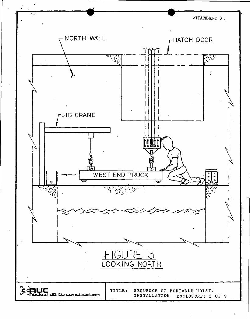
ATTACHMENT 3,
NORTH WA'LL HATCH DOOR
'i:c . <''si.
I~ 0
JIB CRANE
M(EST END TRUCK
~ ~
~I
FIGURE aLOOK lNG NORTH
-nuclear utllltvconatructlnnTITLE: SEQUENCE OF PORTABLE HOIST ~
INSTALLATION ENCLOSURE: 3 OF 9

ATTACHMENT 4
NORTH WALL HATCH DOOR
~,
l, I
JtB CRANEHOLD BACK TO PREVENTFORWARD LUNGE
WEST END TRUCK
~ g ~ ~
FIGURE 4lOOKING NORTH
-nuclear uttl~ cnnatructlnnTITLE: S EQUEN CE OF PORTAB LE HOI S T
INSTALLATION ENCLOSURE: 4 OF 9

~ I

ATTACHMENT 5
NORTH WALL HATCH DOOR
C, 0.
JIB CRANE
V/EST END TRUCK
~ 'h ~
'
FIGURE 5LOOKING NORTH
'.=&4'ADClPRf UClllLLJ CClA%iCAJCCIDA
TITLE: S EQUEN CE OF PORTABLE HOI STINSTALLATION ENCLOSURE I 5 PF 9

ATTACH/KNT 6
GIRDER
NORTH MLL HATCH DOOR
35'-0"
JIB CRANE
I5-0
FIGURE 6LOOKING NORTH
-flUCQSf UtflltLJCOP%tfUCtlCXlTITLE: SEQUENCE OF PORTABLE HOIST
INSTALLATION ENCLOSURE: 6 OF 9

ATTACHNENT 7
NORTH WALLI
HATCH DOOR
A /'';gr .
I ~
'r''r'lB
CRANE
Gl RDER
Ir 'i'1 ~, ~ (
FIGURE 7LOOK!NG NORTl-l
MC',-nuclear utllttu cnrmtructlun
TITLE: SEQUENCE OF PORTABLE HOISTINSTALLATION EN CLOS URF: 7 OF 9

ATTACHHENT 8
NORTH WALL HATCH DOOR
J I B CRANE
SOUTH GIRDER
FIGURE 8LOOK lNG NORTH"
.= ~hfC,'nuclear utilttu ccmstruct>onTI TLE: SEQUENCE OF PORTABLE HOIST
INSTALLATION ENCLOSURE: 8 OF 9

0 ~
A
11
r

~ V
A
ATTACHMENT 91
NORTH WALL HATCH DOOR
" '<:c'.t
Jl B CRANE
PORTA E LEHOIST
SOUTH GIRDER
J
1
0 ~1%
FIGURE 9LOOK lNG NORTt-I
; —. 4-hMC:--tlUCIBBfUtf1~ CC&hSCFUCtlCÃl
TITLE: SEQUENCE OF FORTABLE HOISTINSTALLATION ENCLOSURE..9 PF 9

0'
~ I
t
l ~
N
~ y