SSS Strawman Architecture - Computer graphicsgraphics.stanford.edu/sss/strawman_09apr02.pdf · SSS...
25
SSS Strawman Architecture Bill Dally Ujval Kapasi Mattan Erez Ben Serebrin Timothy Knight Jung Ho Ahn Version 0.6 April 9, 2002
Transcript of SSS Strawman Architecture - Computer graphicsgraphics.stanford.edu/sss/strawman_09apr02.pdf · SSS...
SSS Strawman Architecture
Bill Dally Ujval Kapasi Mattan Erez Ben Serebrin Timothy KnightJung Ho Ahn
Version 0.6April 9, 2002
CONTENTS 2
Contents
1 Introduction 51.1 Document Structure . . . . . . . . . . . . . . . . . . . . . . . . . . . . . . . . . . . . . . . . . 5
2 System Overview 52.1 System Architecture . . . . . . . . . . . . . . . . . . . . . . . . . . . . . . . . . . . . . . . . . 52.2 Stream Processor Architecture . . . . . . . . . . . . . . . . . . . . . . . . . . . . . . . . . . . 62.3 Outline of Operation . . . . . . . . . . . . . . . . . . . . . . . . . . . . . . . . . . . . . . . . . 72.4 Programming the SSS . . . . . . . . . . . . . . . . . . . . . . . . . . . . . . . . . . . . . . . . 72.5 Multiuser / Multiprogramming Support . . . . . . . . . . . . . . . . . . . . . . . . . . . . . . 8
3 Stream Instruction-Set Architecture 83.1 Machine State . . . . . . . . . . . . . . . . . . . . . . . . . . . . . . . . . . . . . . . . . . . . . 8
3.1.1 Scalar Program Counter (PC) . . . . . . . . . . . . . . . . . . . . . . . . . . . . . . . . 83.1.2 Scalar Processor Registers (SPR) . . . . . . . . . . . . . . . . . . . . . . . . . . . . . . 83.1.3 Stream Register File (SRF) . . . . . . . . . . . . . . . . . . . . . . . . . . . . . . . . . 93.1.4 Stream Descriptor Registers (SDR) . . . . . . . . . . . . . . . . . . . . . . . . . . . . . 93.1.5 Memory Address Registers (MAR) . . . . . . . . . . . . . . . . . . . . . . . . . . . . . 93.1.6 Memory Stream Control Registers (MSCR) . . . . . . . . . . . . . . . . . . . . . . . . 93.1.7 Stream Cache (SC) . . . . . . . . . . . . . . . . . . . . . . . . . . . . . . . . . . . . . . 93.1.8 Global Memory (M) . . . . . . . . . . . . . . . . . . . . . . . . . . . . . . . . . . . . . 93.1.9 Segment Registers (SEG) . . . . . . . . . . . . . . . . . . . . . . . . . . . . . . . . . . 93.1.10 Synchronization Primitive State (SYNC) . . . . . . . . . . . . . . . . . . . . . . . . . 9
3.2 Instruction Set . . . . . . . . . . . . . . . . . . . . . . . . . . . . . . . . . . . . . . . . . . . . 93.2.1 Scalar Instructions . . . . . . . . . . . . . . . . . . . . . . . . . . . . . . . . . . . . . . 93.2.2 Stream Load and Store . . . . . . . . . . . . . . . . . . . . . . . . . . . . . . . . . . . 93.2.3 Stream Cache Prefetch . . . . . . . . . . . . . . . . . . . . . . . . . . . . . . . . . . . . 103.2.4 Invalidate Cache Entries . . . . . . . . . . . . . . . . . . . . . . . . . . . . . . . . . . . 103.2.5 Execute Kernel . . . . . . . . . . . . . . . . . . . . . . . . . . . . . . . . . . . . . . . . 103.2.6 Global Sync . . . . . . . . . . . . . . . . . . . . . . . . . . . . . . . . . . . . . . . . . . 103.2.7 Segment Register Manipulation . . . . . . . . . . . . . . . . . . . . . . . . . . . . . . . 10
3.3 Memory Model . . . . . . . . . . . . . . . . . . . . . . . . . . . . . . . . . . . . . . . . . . . . 103.4 Global Communication and Synchronization Mechanisms . . . . . . . . . . . . . . . . . . . . 123.5 Exception / Interrupt Handling . . . . . . . . . . . . . . . . . . . . . . . . . . . . . . . . . . . 12
4 Kernel Instruction-Set Architecture 124.1 Machine State . . . . . . . . . . . . . . . . . . . . . . . . . . . . . . . . . . . . . . . . . . . . . 12
4.1.1 Cluster Local Registers (LR) . . . . . . . . . . . . . . . . . . . . . . . . . . . . . . . . 124.1.2 Cluster Scratchpad Register File (SP) . . . . . . . . . . . . . . . . . . . . . . . . . . . 134.1.3 Cluster Condition Code Registers (CCCR) . . . . . . . . . . . . . . . . . . . . . . . . 134.1.4 Microcontroller Register File (MCR) . . . . . . . . . . . . . . . . . . . . . . . . . . . . 134.1.5 Microcontroller Condition Code Registers (MCCR) . . . . . . . . . . . . . . . . . . . . 134.1.6 Microprogram Counter (MPC) . . . . . . . . . . . . . . . . . . . . . . . . . . . . . . . 134.1.7 Microcode Store (MCS) . . . . . . . . . . . . . . . . . . . . . . . . . . . . . . . . . . . 13
4.2 Microcode Instruction Execution . . . . . . . . . . . . . . . . . . . . . . . . . . . . . . . . . . 134.3 Conditional Execution . . . . . . . . . . . . . . . . . . . . . . . . . . . . . . . . . . . . . . . . 14
5 Microarchitecture 145.1 Scalar Execution Unit . . . . . . . . . . . . . . . . . . . . . . . . . . . . . . . . . . . . . . . . 14
5.1.1 Scalar Processor (SP) . . . . . . . . . . . . . . . . . . . . . . . . . . . . . . . . . . . . 145.1.2 Stream Controller (SCO) . . . . . . . . . . . . . . . . . . . . . . . . . . . . . . . . . . 145.1.3 Processor-Network Interface (PNI) . . . . . . . . . . . . . . . . . . . . . . . . . . . . . 145.1.4 Programmable Interrupt Controller (PIC) . . . . . . . . . . . . . . . . . . . . . . . . . 16
5.2 Stream Execution Unit . . . . . . . . . . . . . . . . . . . . . . . . . . . . . . . . . . . . . . . . 16
April 9, 2002

CONTENTS 3
5.2.1 Arithmetic Cluster (CL) . . . . . . . . . . . . . . . . . . . . . . . . . . . . . . . . . . . 165.2.2 Microcontroller (MC) . . . . . . . . . . . . . . . . . . . . . . . . . . . . . . . . . . . . 165.2.3 Inter-cluster Switch (ICS) . . . . . . . . . . . . . . . . . . . . . . . . . . . . . . . . . . 16
5.3 Stream Register File (SRF) and Stream Buffers (SB) . . . . . . . . . . . . . . . . . . . . . . . 165.4 Memory System . . . . . . . . . . . . . . . . . . . . . . . . . . . . . . . . . . . . . . . . . . . 18
5.4.1 Address Generators (AG) . . . . . . . . . . . . . . . . . . . . . . . . . . . . . . . . . . 185.4.2 Reorder Buffers (ROB) . . . . . . . . . . . . . . . . . . . . . . . . . . . . . . . . . . . 185.4.3 Stream Cache (SC) . . . . . . . . . . . . . . . . . . . . . . . . . . . . . . . . . . . . . . 185.4.4 DRAM Interface (DI) . . . . . . . . . . . . . . . . . . . . . . . . . . . . . . . . . . . . 195.4.5 Memory-Network Interface (MNI) . . . . . . . . . . . . . . . . . . . . . . . . . . . . . 195.4.6 Processor-Memory Interface (PMI) . . . . . . . . . . . . . . . . . . . . . . . . . . . . . 195.4.7 Memory Unit (MU) . . . . . . . . . . . . . . . . . . . . . . . . . . . . . . . . . . . . . 19
5.5 Network and Network Interface (NI) . . . . . . . . . . . . . . . . . . . . . . . . . . . . . . . . 20
6 Feeds and Speeds 206.1 Speeds within the Node . . . . . . . . . . . . . . . . . . . . . . . . . . . . . . . . . . . . . . . 20
6.1.1 Local Bandwidth . . . . . . . . . . . . . . . . . . . . . . . . . . . . . . . . . . . . . . . 216.1.2 Stream Register File . . . . . . . . . . . . . . . . . . . . . . . . . . . . . . . . . . . . . 216.1.3 Cache . . . . . . . . . . . . . . . . . . . . . . . . . . . . . . . . . . . . . . . . . . . . . 216.1.4 DRDRAM Local Memory . . . . . . . . . . . . . . . . . . . . . . . . . . . . . . . . . . 21
6.2 Speeds across the system . . . . . . . . . . . . . . . . . . . . . . . . . . . . . . . . . . . . . . . 216.2.1 Card-level Speed . . . . . . . . . . . . . . . . . . . . . . . . . . . . . . . . . . . . . . . 216.2.2 Backplane Speed . . . . . . . . . . . . . . . . . . . . . . . . . . . . . . . . . . . . . . . 216.2.3 System Speeds . . . . . . . . . . . . . . . . . . . . . . . . . . . . . . . . . . . . . . . . 21
7 Area and Power Estimates 21
8 Parameters and Ranges 21
9 Issues 229.1 Open . . . . . . . . . . . . . . . . . . . . . . . . . . . . . . . . . . . . . . . . . . . . . . . . . . 22
9.1.1 Virtual Memory . . . . . . . . . . . . . . . . . . . . . . . . . . . . . . . . . . . . . . . 229.1.2 Memory Coherence . . . . . . . . . . . . . . . . . . . . . . . . . . . . . . . . . . . . . . 229.1.3 Dependency Information . . . . . . . . . . . . . . . . . . . . . . . . . . . . . . . . . . . 229.1.4 Aspect Ratio and Layout of Execution Units . . . . . . . . . . . . . . . . . . . . . . . 229.1.5 Conditional support . . . . . . . . . . . . . . . . . . . . . . . . . . . . . . . . . . . . . 229.1.6 Inter-cluster Switch Implementation . . . . . . . . . . . . . . . . . . . . . . . . . . . . 229.1.7 Register File Organization . . . . . . . . . . . . . . . . . . . . . . . . . . . . . . . . . . 239.1.8 Integer Unit in Clusters . . . . . . . . . . . . . . . . . . . . . . . . . . . . . . . . . . . 239.1.9 Memory Locking . . . . . . . . . . . . . . . . . . . . . . . . . . . . . . . . . . . . . . . 239.1.10 Multidimensional Strides . . . . . . . . . . . . . . . . . . . . . . . . . . . . . . . . . . 23
9.2 Closed . . . . . . . . . . . . . . . . . . . . . . . . . . . . . . . . . . . . . . . . . . . . . . . . . 239.2.1 SRF, SB, SC . . . . . . . . . . . . . . . . . . . . . . . . . . . . . . . . . . . . . . . . . 239.2.2 Stream Cache . . . . . . . . . . . . . . . . . . . . . . . . . . . . . . . . . . . . . . . . . 239.2.3 Parallelism Within the Node . . . . . . . . . . . . . . . . . . . . . . . . . . . . . . . . 239.2.4 Fetch-and-Op . . . . . . . . . . . . . . . . . . . . . . . . . . . . . . . . . . . . . . . . . 239.2.5 Inter-cluster Switch Placement . . . . . . . . . . . . . . . . . . . . . . . . . . . . . . . 249.2.6 Memory Segment Sizes . . . . . . . . . . . . . . . . . . . . . . . . . . . . . . . . . . . . 249.2.7 Number of Stream Buffers . . . . . . . . . . . . . . . . . . . . . . . . . . . . . . . . . . 249.2.8 Support for Debugging of Software . . . . . . . . . . . . . . . . . . . . . . . . . . . . . 249.2.9 General Purpose Timers . . . . . . . . . . . . . . . . . . . . . . . . . . . . . . . . . . . 249.2.10 Multicasting . . . . . . . . . . . . . . . . . . . . . . . . . . . . . . . . . . . . . . . . . 249.2.11 SIMD Floaing Point Units . . . . . . . . . . . . . . . . . . . . . . . . . . . . . . . . . . 259.2.12 L2 Cache . . . . . . . . . . . . . . . . . . . . . . . . . . . . . . . . . . . . . . . . . . . 259.2.13 SRF Random Access . . . . . . . . . . . . . . . . . . . . . . . . . . . . . . . . . . . . 25
April 9, 2002
LIST OF FIGURES 4
List of Figures
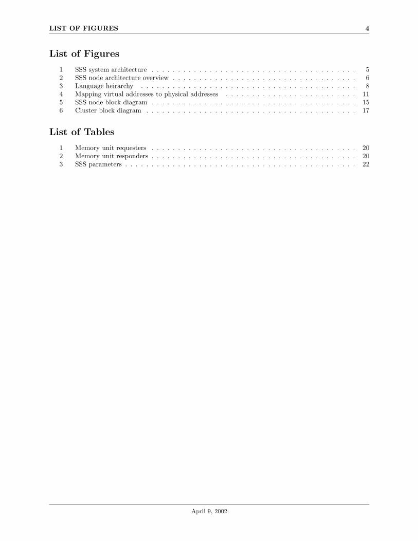
1 SSS system architecture . . . . . . . . . . . . . . . . . . . . . . . . . . . . . . . . . . . . . . . 52 SSS node architecture overview . . . . . . . . . . . . . . . . . . . . . . . . . . . . . . . . . . . 63 Language heirarchy . . . . . . . . . . . . . . . . . . . . . . . . . . . . . . . . . . . . . . . . . 84 Mapping virtual addresses to physical addresses . . . . . . . . . . . . . . . . . . . . . . . . . 115 SSS node block diagram . . . . . . . . . . . . . . . . . . . . . . . . . . . . . . . . . . . . . . . 156 Cluster block diagram . . . . . . . . . . . . . . . . . . . . . . . . . . . . . . . . . . . . . . . . 17
List of Tables
1 Memory unit requesters . . . . . . . . . . . . . . . . . . . . . . . . . . . . . . . . . . . . . . . 202 Memory unit responders . . . . . . . . . . . . . . . . . . . . . . . . . . . . . . . . . . . . . . . 203 SSS parameters . . . . . . . . . . . . . . . . . . . . . . . . . . . . . . . . . . . . . . . . . . . . 22
April 9, 2002

1 Introduction 5
1 Introduction
The SSS is intended as a cost-effective target for numerical applications expressed as stream programs in alanguage such as Brook [6]. The goal is to achieve a cost/performance ratio 100x better than conventionalcluster based supercomputers on both arithmetic limited and memory-bandwidth limited computations.
The SSS exploits the stream model [5] to expose the locality available in an application, uses a streamarchitecture [1] to exploit this locality, and provides a large number of floating-point units per node to convertthe resulting high-level of arithmetic intensity into performance.
The latency hiding of stream memory operations in combination with a high-bandwidth memory systemachieves cost effectiveness on memory-limited applications.
1.1 Document Structure
Section 2 gives a high-level description of the SSS, covering the various aspects of the system breifly. Sections3 and 4 present the programmer’s model of the machine, and 5 specifies the SSS architecture. Sections 6and 7 summarise the speeds of various components of the SSS and present estimates of the area and powerconsumption of the chip specified in 5. Section 8 enumerates various parameters of the SSS which will betuned based upon the results of simulations, and section 9 lists all of the open issues related to this document.
2 System Overview
2.1 System Architecture
StreamProcessor64 FPUs
64GFLOPS
16 x DRDRAM2GBytes
38GBytes/s
20GBytes/s32+32 pairs
Node
On-Board Network
Node2
Node16 Board 2
16 Nodes1K FPUs1TFLOPS32GBytes
Intra-Cabinet Network(passive - wires only)
Board 64
160GBytes/s256+256 pairs
10.5" Teradyne GbX
Board
Inter-Cabinet Network
Cabinet 264 Boards1K Nodes64K FPUs64TFLOPS
2TBytes
5TBytes/s8K+8K links
Ribbon Fiber
Cabinet 16
Bisection 64TBytes/s
All links 5Gb/s per pair or fiberAll bandwidths are full duplex
E/OO/E
Cabinet
Figure 1: SSS system architecture
April 9, 2002
2.2 Stream Processor Architecture 6
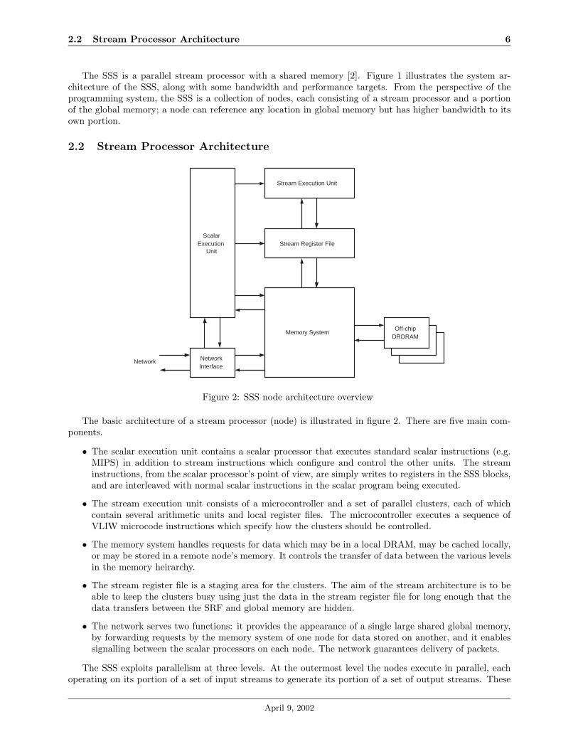
The SSS is a parallel stream processor with a shared memory [2]. Figure 1 illustrates the system ar-chitecture of the SSS, along with some bandwidth and performance targets. From the perspective of theprogramming system, the SSS is a collection of nodes, each consisting of a stream processor and a portionof the global memory; a node can reference any location in global memory but has higher bandwidth to itsown portion.
2.2 Stream Processor Architecture
Stream Execution Unit
Stream Register File
Memory System
NetworkInterface
ScalarExecution
Unit
texttext
Off-chipDRDRAM
Network
Figure 2: SSS node architecture overview
The basic architecture of a stream processor (node) is illustrated in figure 2. There are five main com-ponents.
• The scalar execution unit contains a scalar processor that executes standard scalar instructions (e.g.MIPS) in addition to stream instructions which configure and control the other units. The streaminstructions, from the scalar processor’s point of view, are simply writes to registers in the SSS blocks,and are interleaved with normal scalar instructions in the scalar program being executed.
• The stream execution unit consists of a microcontroller and a set of parallel clusters, each of whichcontain several arithmetic units and local register files. The microcontroller executes a sequence ofVLIW microcode instructions which specify how the clusters should be controlled.
• The memory system handles requests for data which may be in a local DRAM, may be cached locally,or may be stored in a remote node’s memory. It controls the transfer of data between the various levelsin the memory heirarchy.
• The stream register file is a staging area for the clusters. The aim of the stream architecture is to beable to keep the clusters busy using just the data in the stream register file for long enough that thedata transfers between the SRF and global memory are hidden.
• The network serves two functions: it provides the appearance of a single large shared global memory,by forwarding requests by the memory system of one node for data stored on another, and it enablessignalling between the scalar processors on each node. The network guarantees delivery of packets.
The SSS exploits parallelism at three levels. At the outermost level the nodes execute in parallel, eachoperating on its portion of a set of input streams to generate its portion of a set of output streams. These
April 9, 2002
2.3 Outline of Operation 7
streams need not be entirely local to the node, but performance will benefit if they are. The nodes commu-nicate and synchronize with one another at the end of each parallel stream operation.
At the middle level, the clusters of the stream processor operate on several adjacent elements of the localportion of the stream simultaneously. This inner-loop parallelism exploits the on-chip communication thatexists within a single node.
Finally, at the innermost level, the floating-point units within each cluster exploit instruction-level par-allelism.
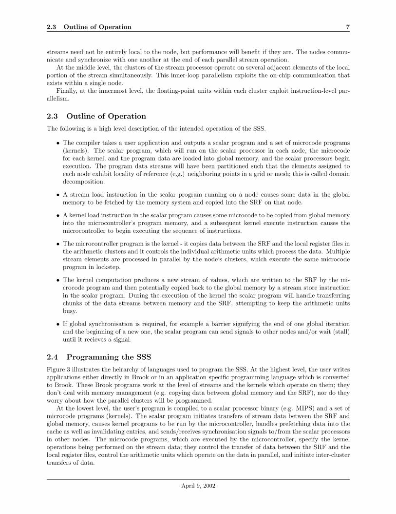
2.3 Outline of Operation
The following is a high level description of the intended operation of the SSS.
• The compiler takes a user application and outputs a scalar program and a set of microcode programs(kernels). The scalar program, which will run on the scalar processor in each node, the microcodefor each kernel, and the program data are loaded into global memory, and the scalar processors beginexecution. The program data streams will have been partitioned such that the elements assigned toeach node exhibit locality of reference (e.g.) neighboring points in a grid or mesh; this is called domaindecomposition.
• A stream load instruction in the scalar program running on a node causes some data in the globalmemory to be fetched by the memory system and copied into the SRF on that node.
• A kernel load instruction in the scalar program causes some microcode to be copied from global memoryinto the microcontroller’s program memory, and a subsequent kernel execute instruction causes themicrocontroller to begin executing the sequence of instructions.
• The microcontroller program is the kernel - it copies data between the SRF and the local register files inthe arithmetic clusters and it controls the individual arithmetic units which process the data. Multiplestream elements are processed in parallel by the node’s clusters, which execute the same microcodeprogram in lockstep.
• The kernel computation produces a new stream of values, which are written to the SRF by the mi-crocode program and then potentially copied back to the global memory by a stream store instructionin the scalar program. During the execution of the kernel the scalar program will handle transferringchunks of the data streams between memory and the SRF, attempting to keep the arithmetic unitsbusy.
• If global synchronisation is required, for example a barrier signifying the end of one global iterationand the beginning of a new one, the scalar program can send signals to other nodes and/or wait (stall)until it recieves a signal.
2.4 Programming the SSS
Figure 3 illustrates the heirarchy of languages used to program the SSS. At the highest level, the user writesapplications either directly in Brook or in an application specific programming language which is convertedto Brook. These Brook programs work at the level of streams and the kernels which operate on them; theydon’t deal with memory management (e.g. copying data between global memory and the SRF), nor do theyworry about how the parallel clusters will be programmed.
At the lowest level, the user’s program is compiled to a scalar processor binary (e.g. MIPS) and a set ofmicrocode programs (kernels). The scalar program initiates transfers of stream data between the SRF andglobal memory, causes kernel programs to be run by the microcontroller, handles prefetching data into thecache as well as invalidating entries, and sends/receives synchronisation signals to/from the scalar processorsin other nodes. The microcode programs, which are executed by the microcontroller, specify the kerneloperations being performed on the stream data; they control the transfer of data between the SRF and thelocal register files, control the arithmetic units which operate on the data in parallel, and initiate inter-clustertransfers of data.
April 9, 2002

2.5 Multiuser / Multiprogramming Support 8
ApplicationSpecific
Language
ApplicationSpecific
Language
Brook
Intermediate Representation(s):Stream Virtual Machine, StreamC/KernelC, etc.
ScalarMachine
Code(e.g.) MIPS
MicrocodeVLIW
Instructions(Kernel)
MicrocodeVLIW
Instructions(Kernel)
Figure 3: Language heirarchy
The compilation and runtime systems are expected to be able to perform the following transformationson the high-level program written in Brook:
• Partition the streams of data across nodes (domain decomposition). For example, if a program usesa 1024 × 1024 stream and runs on a 64-node SSS, the programmign system could assign a 128 × 128submatrix to each node. Unlike domain decomposition on cluster machines, the submatrices on eachnode need not be overlapped since the node can reference data in the adjoining submatrices if it isneeded.
• Schedule the arithmetic units and allocate local registers for the execution of kernels, including splittingor merging kernels to maximize the ratio of computation to memory operations.
• Schedule the transfers of stream data between the SRF and global memory, ensuring that the sizes ofthe transferred chunks don’t cause the kernel to spill tremporary variables (strip-mining).
• Insert instructions in the scalar code to synchronize the nodes where necessary.
• Convert if-statements and conditional loops to either predicated execution or conditional streams.
2.5 Multiuser / Multiprogramming Support
Each node in the SSS can run at most one program at a time, and several nodes can be running thesame program collaboratively. Different programs can be executing on different nodes, however, and theseprograms share the complete global memory space of all the nodes combined. Memory segmentation, specifiedvia a set of segment registers, is used to protect different programs from each other.
3 Stream Instruction-Set Architecture
3.1 Machine State
Each stream processor operates on the following state.
3.1.1 Scalar Program Counter (PC)
Contains the memory address of the next instruction to be executed by the scalar processor.
3.1.2 Scalar Processor Registers (SPR)
The register set of the scalar processor - a standard MIPS or ARM set with some stream extensions.
April 9, 2002

3.2 Instruction Set 9
3.1.3 Stream Register File (SRF)
A single SSRF -word register file. Contiguous data can be transferred in parallel between the SRF and thestream buffers.
3.1.4 Stream Descriptor Registers (SDR)
The NSDR stream descriptor registers are used to hold descriptions of streams in the SRF.
3.1.5 Memory Address Registers (MAR)
The memory address registers hold descriptions of vector address streams for the memory system.
3.1.6 Memory Stream Control Registers (MSCR)
Each address generator contains a memory stream control register, which contains information about thestream the address generator is fetching or storing. When a stream instruction initiates a stream transfervia the address generators, the MAR with the stream info is specified along with details of the operation toperform, and this information is stored in the address generator’s MSCR.
3.1.7 Stream Cache (SC)
A SSC-word register file that acts as a special cache and is accessed with memory addresses. It is intendedto support graph streams efficiently. It is exposed in the ISA but is not software managed.
3.1.8 Global Memory (M)
The contents of all of the memory in the machine. Physical memory addresses are partitioned into node andoffset.
3.1.9 Segment Registers (SEG)
A set of NSEG special registers for implementing the memory model of section 3.3.
3.1.10 Synchronization Primitive State (SYNC)
State kept by the system to allow the implementation of the synchronization primitives described in section3.4.
3.2 Instruction Set
The scalar processor in each node executes a single instruction sequence indexed by the program counter.The instruction set includes the following instuction types.
3.2.1 Scalar Instructions
A standard RISC instruction (e.g. MIPS). Note that from the perspective of the scalar processor, the otherinstructions in this list are all regular RISC instructions; they are implemented as writes to the streamcontroller.
3.2.2 Stream Load and Store
Copy a stream of records between the SRF and global memory. The records can be of arbitrary length andcan be located in memory on a regular stride. Additionally, an index stream can be used to specify a listof addresses of memory locations to copy data to or from. Streams in both memory and the SRF/SC areidentified by register-mapped stream descriptors (SDRs). Each stream operation specifies whether or notthe stream cache (SC) may be used.
April 9, 2002

3.3 Memory Model 10
3.2.3 Stream Cache Prefetch
Prefetches a set of records into the stream cache.
3.2.4 Invalidate Cache Entries
Support for single line invalidates, as well as setting bits used for gang-invalidates [7].
3.2.5 Execute Kernel
Execute a kernel (specified by a register mapped kernel instruction pointer) on a set of streams (specifiedby register mapped stream descriptors). Dependency information will be passed to the stream controllerexplicitly in the instruction(s) from the scalar processor.
3.2.6 Global Sync
A set of instructions to set up and invoke the synchronization primitives described in section 3.4.
3.2.7 Segment Register Manipulation
OS priviledged instructions for reading and setting the segment registers described in section 3.3.
3.3 Memory Model
To allow multiple jobs to be run on the SSS simultaneously - the intended mode is space shared - memoryis protected via segmentation. The 64-bit virtual addresses used by the SSS are relative to the node inwhich they are issued, and segment registers in each node are used to convert the virtual addresses to 64-bitphysical addresses which are absolute across the entire system. Note that although both the physical andvirtual addresses refer to a byte offset in memory, they are restricted to being word aligned - the lower 6bits of each are assumed to be 0 and are ignored by the memory system. Figure 4 illustrates the mappingprocess, under the assumptions that there are at most 214 nodes, each node has 231 bytes of local memory,and there are 32 segment registers. The process is as follows:
• The SegNum field of the virtual address is used to index the segment register file.
• The n0 and n1 fields of the segment register are used to partition the SegAddr field of the virtualaddress into the physical memory offset (PhysOffHi : PhysOffLo) and the NodeOff field.
• The node to which the virtual address is referring is calculated by adding NodeBase, the start of thecontiguous range of nodes in the segment, to NodeOff .
• The absolute physical address (PhysAddr) within the determined node (Node) is computed by addingPhysOff to PhysBase.
• The physical address must fall within the segment memory range in the node, namely PhysBase toPhysBase + 2PhysLen − 1. Note that the minimum segment size allowed is 26 bytes, (i.e.) PhysLenmust be greater than 6, and the base physical address (PhysBase) must be word-aligned.
Within each segment, the virtual addresses (SegAddr) are contiguous and run from 0 up to 2PhysLen+x−1,where x = n1−n0+1 and 2x is the number of nodes in the segment. Physically, however, due to the way thevirtual addresses are converted to physical addresses, the segment data may be interleaved across a numberof nodes. For example, a segment register could specify that a segment over 16 nodes, starting at node 32(NodeBase = 32), is 4 GBytes in size (total) and hence uses 256 MBytes from each node (PhysLen = 28),starts at physical address 1 GBytes within each node (PhysBase = 30), and is striped across the nodes in1 MByte increments (n0 = 10 and n1 = 13).
The segment registers also specify the stream cache policy for their addresses via the Cach field. Asegment which is marked as cacheable allows data to be cached (optional, depending on the instructions),
April 9, 2002

3.3 Memory Model 11
Node PhysAddrreservedPA:
PhysOff
+
SegAddrSegNum reservedVA:
PhysOffHi NodeOff PhysOffLo
+
n0
Ca
chP
hys
Ba
sen
1re
serv
ed
SR
[ S
egN
um
]:
Ph
ysLe
nN
ode
Ba
se
0(31+n1-n0)5963
(n1+1) n1 n0 (n0-1) 0(31+n1-n0)
030
0305063
03
03
13
63
74
24
35
65
76
16
2
Figure 4: Mapping virtual addresses to physical addresses
April 9, 2002

3.4 Global Communication and Synchronization Mechanisms 12
and a segment which is marked non-cacheable will never allow data to be cached, regardless of the instructionsissued. The stream cache supports read-only semantics with explicit invalidation.
The scalar processor can issue both virtual and physical addresses; the processor-memory interface acceptsa special “bypass address translation” bit in the address issued, and interprets the SegAddr field as simplythe physical address within the current node. This feature is intended for OS use only, however, and is onlyenabled when the scalar processor is in priveliged mode.
3.4 Global Communication and Synchronization Mechanisms
The scalar processor in each node can send and receive messages over the network to and from the scalarprocessors in other nodes. Packets which are related to memory requests and responses are handled by thememory-network interface. The messaging packets which are sourced / sinked by the processor-networkinterface are of the following types:
• Fetch-and-Op: A processor can request that a remote node perform an operation on it’s local data,possibly returning the result. Each fetch-and-op request can carry an arbitrary word of data, allow-ing the efficient implementation of reduction operations. Examples of operations are fetch-and-add,compare-and-swap, etc., and arbitrary operations can be specified by user-defined functions within thescalar program which are called by the message handler which processes the requests. Upon receptionof a fetch-and-op request, the scalar processor will read the specified memory values, perform the op-erations, and if required send the result back to the requesting node. Note that the stream (parallel)execution units are not involved.
• Barrier Signal: The processors can signal when they reach a given point in their programs, and/orthey can wait until they receive a signal from another node. The signal will refer to a named barrier,which could be a general global barrier or a specifically tuned pairwise barrier.
• General Purpose Signal: The processors can also send non-barrier signals to each other for user-defined purposes. An example of an application of these signals would be in the case of multiple nodessearching for a solution within their own local portion of the data; once one node finds a match, it cansignal the other nodes to notify them to stop searching.
In addition to sending messages over the network, processors can communicate and synchronize witheach other by using the global shared memory.
3.5 Exception / Interrupt Handling
Conceptually, kernel and scalar operations are atomic and exceptions can be checked after each streamoperation. Error conditions which arise inside the cluster arithmetic units, such as divide-by-0, will cause astatus bit to be set, and will possibly result in a NaN floating point value.
The scalar processor can be interrupted by both the stream controller and the processor-network inter-face. These interrupts are maskable, and the processor can poll a status register in each instead of beingasynchronously interrupted if the programmer so desires.
4 Kernel Instruction-Set Architecture
This section presents the programmer-visible elements of the architecture which are related to the processingof stream elements within the clusters.
4.1 Machine State
4.1.1 Cluster Local Registers (LR)
Each of the arithmetic clusters contain a set of SLR-word two-port local register files, one on each input ofeach functional (arithmetic) unit.
April 9, 2002
4.2 Microcode Instruction Execution 13
4.1.2 Cluster Scratchpad Register File (SP)
A SSP -word indexable register file in each cluster that is used for temporary storage such as local registerspills and lookup tables.
4.1.3 Cluster Condition Code Registers (CCCR)
Each arithmetic cluster also contains a condition code register which contains the usual arithmetic conditioncodes and is used for predicated execution as well as conditional streams.
4.1.4 Microcontroller Register File (MCR)
The SMCR-word microcontroller register file can hold arbitrary data written by the microcontroller. Specif-ically, it is used to hold loop counters as well as data to be broadcast to some or all of the clusters. It canalso be used to pass values from a microprogram to the scalar processor and vice versa. There is a singlemicrocontroller register file in each node.
4.1.5 Microcontroller Condition Code Registers (MCCR)
The microcontroller condition code registers are used as branching conditions for loop operations in micro-programs. There is a single microcontroller condition code register file in each node.
4.1.6 Microprogram Counter (MPC)
The microprogram counter is located in the microcontroller, and is simply a pointer into the microcodestore which indicates the currently executing microcode instruction. There is a single microprogram counterregister in each node.
4.1.7 Microcode Store (MCS)
The microcode store is a SMCS-byte register file that holds the microcode instructions which are to beissued by the microcontroller to the arithmetic clusters. Microcode is loaded into the microcode store viathe stream register file.
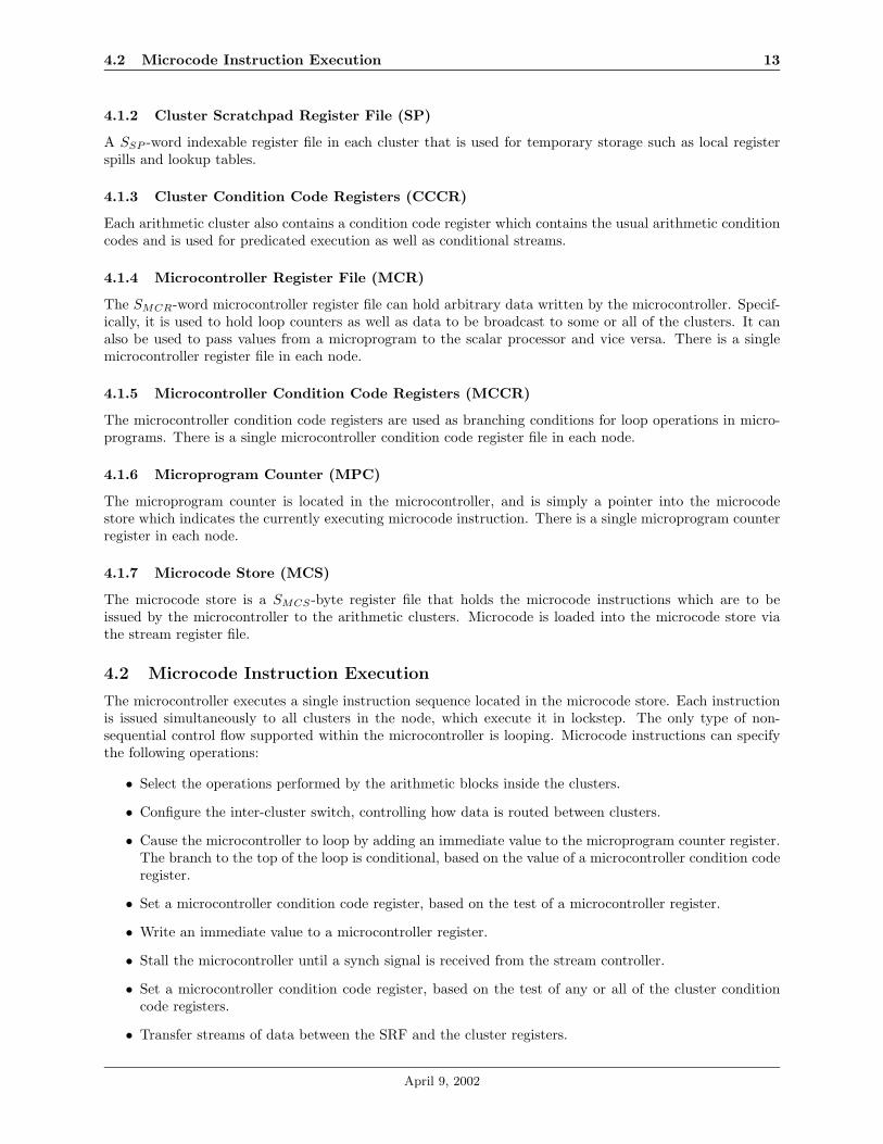
4.2 Microcode Instruction Execution
The microcontroller executes a single instruction sequence located in the microcode store. Each instructionis issued simultaneously to all clusters in the node, which execute it in lockstep. The only type of non-sequential control flow supported within the microcontroller is looping. Microcode instructions can specifythe following operations:
• Select the operations performed by the arithmetic blocks inside the clusters.
• Configure the inter-cluster switch, controlling how data is routed between clusters.
• Cause the microcontroller to loop by adding an immediate value to the microprogram counter register.The branch to the top of the loop is conditional, based on the value of a microcontroller condition coderegister.
• Set a microcontroller condition code register, based on the test of a microcontroller register.
• Write an immediate value to a microcontroller register.
• Stall the microcontroller until a synch signal is received from the stream controller.
• Set a microcontroller condition code register, based on the test of any or all of the cluster conditioncode registers.
• Transfer streams of data between the SRF and the cluster registers.
April 9, 2002

4.3 Conditional Execution 14
4.3 Conditional Execution
The only conditional operation supported at the microcontroller level is looping, due to the fact that a singlestream of microcode instructions is broadcast to all clusters within a node, which execute them in lockstep.At the cluster level, predicated execution is used to enable if-then-else constructs without branching; bothhalves of the if-then-else construct are executed in lockstep by all clusters, but the register write operationsare only committed in either the if-block or the else-block on a per-cluster basis, depending on the result ofthe boolean condition evaluation.
Support for conditional streams [3] is also provided, by allowing the stream buffers to be independantacross clusters and using the inter-cluster switch to route the data between the stream buffers and theclusters.
5 Microarchitecture
The top-level node block diagram is shown in figure 5. This section describes the functionality of each block.
5.1 Scalar Execution Unit
5.1.1 Scalar Processor (SP)
The scalar processor executes a standard RISC instruction set (e.g. MIPS). Stream instructions, as describedin section 3.2, are implemented as writes to the stream controller block, and are interleaved with the ‘scalar’instructions in a single logical thread of execution.
A minimal run-time OS will execute on the scalar processor. The OS is responsible for loading andexecuting the scalar programs and may be involved in the implementation of the synchronisation primitivesdiscussed in 3.4.
The scalar processor has its own private I- and D-caches. It shares the same global memory space asthe streaming portion of the architecture, into which it can make byte-wise memory references through theprocessor-memory interface.
5.1.2 Stream Controller (SCO)
The scalar processor issues stream commands to the stream controller, which performs the following tasks.
• Decodes the command from the scalar processor, which includes explicit dependency information.
• Keeps a scoreboard of pending instructions and their dependencies, as well as available resources. Aninstruction will be issued to the SSS blocks when its dependencies are met and the resources it requiresare free.
• A mask of available scoreboard entries is provided to the scalar processor to enable the program todetermine when the stream controller can accept a stream instruction.
• Optionally, the stream controller could interrupt the scalar processor when the scoreboard transitionsfrom full to not full.
5.1.3 Processor-Network Interface (PNI)
The processor-network interface block is responsible for enabling the scalar processor to send and receivemessages over the network. The types of message packets which can be sent and received are enumerated insection 3.4. The processor-network interface performs the following two tasks.
• The scalar processor can write a message-send command to the block, which will package the messageinto the network packet format and transmit it to the destination node.
• Upon reception of a message packet from another node, the block will decode the packet and storethe message in a register which is readable by the scalar processor. In addition, there is a maskableinterrupt which may be asserted to notify the processor of the arrival of a message.
April 9, 2002

5.1 Scalar Execution Unit 15
Memory Unit
Stream
Cache
DRAM
Interface
Memory-
Network
Interface
Address
Generators
Reorder
Buffers
Processor-
Memory
Interface
texttext
Stream Register File
+
Stream Buffers
Stream
Controller
Scalar Processor
Processor-
Network
Interface
Off-chip
DRDRAM
Network
Stream Processor
Network
Interface
Micro-
controller
Cluster
0
Cluster
(NCL
- 1)
Inter-cluster Switch
Stream Execution Unit
Memory
System
Scalar Execution Unit
Programmable
Interrupt
Controller
Figure 5: SSS node block diagram
April 9, 2002

5.2 Stream Execution Unit 16
5.1.4 Programmable Interrupt Controller (PIC)
The scalar processor can potentially receive interrupts from multiple sources, including the processor-networkinterface and the stream controller. This block would provide a simple interface for the scalar program tomask and unmask the individual interrupt sources, as well as providing a global interrupt enable/disable bitthat the program could write.
The processor will receive status signals from various blocks in the chip, and these signals will be presentedas status bits to the program. To ensure that the software developers and compiler writers using the SSS havemaximum flexibility, these status bits should also generate maskable interrupts from the interrupt controllerwhen they transition from 0 to 1. The status bit interrupts would be deasserted by the processor via aclear-on-write protocol.
5.2 Stream Execution Unit
5.2.1 Arithmetic Cluster (CL)
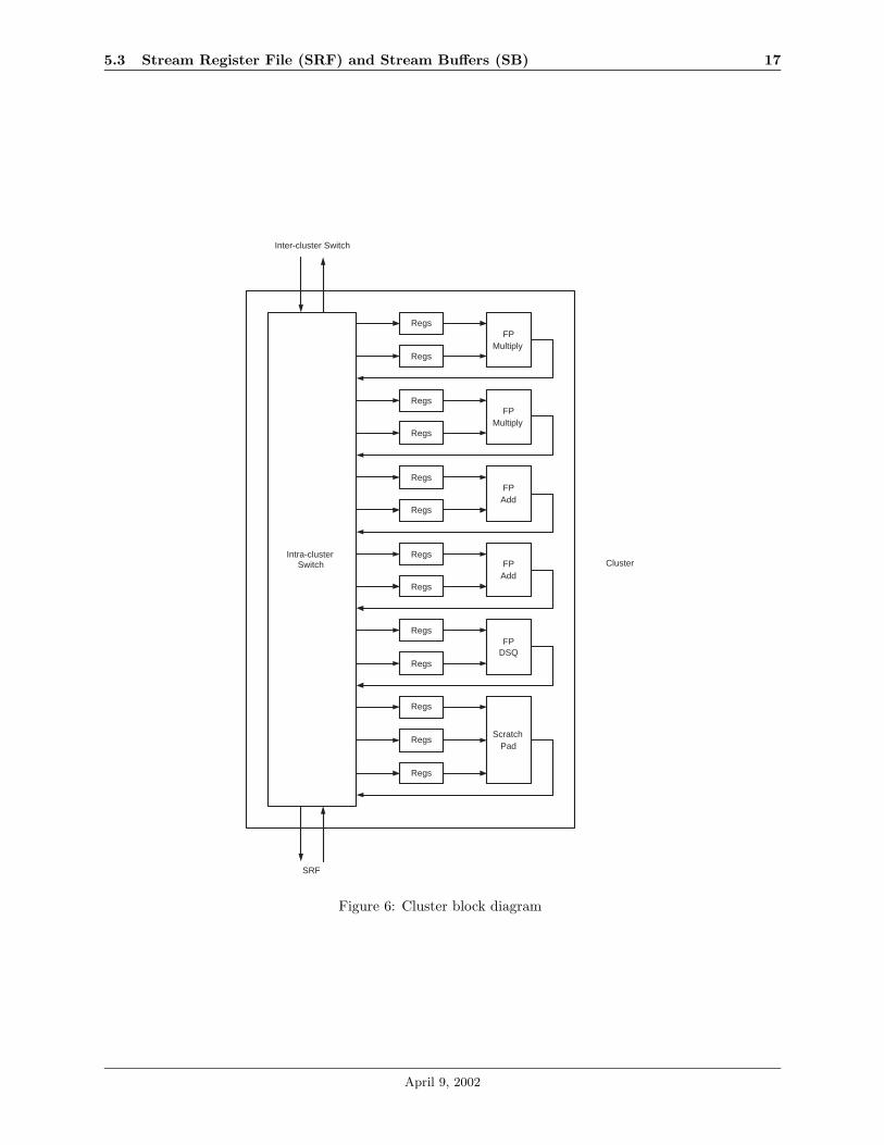
Each node contains NCL identical arithmetic clusters which consist of several functional units, local registerfiles, and an intra-cluster switch. Figure 6 illustrates the cluster architecture.
The functional units can only read from their own local register files, and the functional unit outputs arewritten back to one of the local register files in the cluster. The microcontroller is responsible for transferringdata between the local register files and the SRF.
Each cluster consists of two double-precision floating point adders, two multipliers, and one divide/squareroot unit. Each local register file contains SLRF 64-bit entries. All functional units other than the di-vide/square root unit are fully pipelined.
In addition, each cluster contains a scratchpad which is a set of SSP 64-bit indexible registers used fortemporary storage such as register spills and lookup tables. The scratchpad is controlled similarly to anexecution unit and can process one read and one write per cycle.
5.2.2 Microcontroller (MC)
The functional units, local register files, intra-cluster switches, and inter-cluster switch are controlled by themicrocontroller, which executes a statically scheduled VLIW instruction sequence. The instructions, whichconstitute a kernel, are located in the microcode store. The microcontroller broadcasts the same instructionto all the clusters, which operate in a SIMD fashion.
The microcode program executed by the microcontroller is responsible for initiating data transfers be-tween the local register files and the SRF, and also between the clusters via the inter-cluster switch. Transfersto and from the SRF are via the stream buffers, and the microcontroller will stall execution if either thedata being read from the SRF is not yet available in the SB or if the SB is full and cannot accept the databeing written to the SRF.
The microcontroller has a set of registers which can store loop counters and other values required by themicrocode program.
5.2.3 Inter-cluster Switch (ICS)
The inter-cluster switch is implemented as a crossbar, with each cluster able to write one word per cycle andread one word per cycle (throughput).
5.3 Stream Register File (SRF) and Stream Buffers (SB)
The stream register file is a SSRF -word memory that is accessable by the arithmetic clusters, memory system(address generators) and scalar processor. The basic unit of access is a stream transfer, which is initiatedby a stream instruction executed by the scalar processor. Each stream operation will specify a direction, abase address into the SRF, a count (n), and whether the count is variable. The direction parameter specifieswhether the stream transfer is reading from or writing to the SRF core memory.
If the number of elements accessed is predictable then the stream operation will terminate after n elementshave been transferred; otherwise, if the number of elements is variable, then the count represents a maximum
April 9, 2002
5.3 Stream Register File (SRF) and Stream Buffers (SB) 17
Intra-clusterSwitch
Regs
Regs
FPMultiply
Regs
Regs
FPMultiply
Regs
Regs
FPAdd
Regs
Regs
FPAdd
Regs
Regs
FPDSQ
Regs
RegsScratch
Pad
Regs
SRF
Inter-cluster Switch
Cluster
Figure 6: Cluster block diagram
April 9, 2002

5.4 Memory System 18
length. In the latter case, the stream operation will terminate either when the client asserts an end-of-stream(EOS) signal or if n elements have been transferred. Accesses to the SRF are linear, with n consecutivestream elements transfered starting at the base address.
A set of stream buffers handles all flow control and data transfers between the SRF core and clients.Stream buffer access to the SRF is time-multiplexed but very wide, avoiding the necessity of having amulti-ported SRF to support multiple clusters accessing it simultaneously. Essentially, each stream transferis assigned to a particular SB, and the connectivity of SBs to clients is such that each client has its owndedicated set of SBs. The SBs logically function like a FIFO between the SRF and the client. The streambuffers are also used to implement conditional streams as described in [3].
Note that the stream buffers are not all identical; certain stream buffers can be configured to transferdata in both directions, while some are limited to only one. Additionally, the amount of bandwidth betweenthe SB and the client is potentially different for each client.
The SRF is partitioned into multiple banks, and each cluster is only able to access data aligned to itspartition; random access is not supported.
5.4 Memory System
5.4.1 Address Generators (AG)
Each node accesses memory by issuing stream load and store commands to the address generators. Therole of the address generators is to issue single word memory requests to the memory unit. These are basedeither on a strided access by specifying a base, record size, and number of records, or on an indirect accessvia a stream of indices. The AGs also support bit-reversed addressing. There are NAG address generators,each of width WAG, supporting a total of NAG × WAG word requests per cycle.
5.4.2 Reorder Buffers (ROB)
Along side the address generators is a set of memory reorder buffers that accept/supply data to/from theSRF, essentially acting as an indexable stream buffer. Each ROB holds the identifier of the stream it isbuffering. When an AG sends a request to the memory system it first allocates an entry in the ROB andsends the entry number along with the request to the memory unit, which appends the AG number and theROB entry number to all of its requests and replies.
Note that this mechanism avoids the need for the MSHRs and associative memory which were used inImagine [4]. The penalty for discarding MSHRs, though, is that multiple outstanding requests for the sameword result in multiple memory accesses, but we expect these to be few and that the stream cache willcapture the bulk of repeatedly accessed memory locations. The ordering is up to the user, and can be doneby an an “ordering” kernel.
5.4.3 Stream Cache (SC)
The stream cache may be useful in the following ways.
• Graph streams exhibit temporal locality rather than the spatial locality exploited by the SRF. Thestream cache will be used to selectively cache graph elements.
• There are applications that don’t know which particular elements of a stream they will be accessingand in what order a priori, but whose accesses do exhibit neighbor locality. Examples are the class ofproblems that require a PDE solver to traverse an unstructured graph or mesh as well as texture mapand z-buffer accesses in graphics programs.
The stream cache is physically-addressed and physically-tagged. The segment registers in each nodecontain a bit which indicates the caching policy of the segment, either cacheable or non-cacheable. Requestsfrom the address generators will use the cache only if the segment is marked cacheable and the requestspecifically instructs that the cache should be used; if either of these conditions are not met, the cache willnot be accessed. Memory requests from other blocks (MNI, PMI) never use the cache.
The coherence policy for the stream cache, described in [7], is summarized as follows.
April 9, 2002

5.4 Memory System 19
• Cache entries can be marked as read-only, guaranteeing that when they are flushed from the cache nowrite-back is required. The stream model, in which data is not modified in-place, enables the use ofread-only cache entries without losing any generality.
• Gang invalidation is used to invalidate a large portion of the cache at once. This is useful due tothe fact that many applications contain different computation phases separated by synchronizationboundaries. The cache supports two distinct logical regions (A and B), and allows the program toinvalidate an entire region at once.
• Cache entries which are not marked read-only use a write-back policy. There is a danger here of thedifferent nodes in the system containing inconsistent copies of the same global memory value, and thescalar program, which has explicit control over which addresses may be cached and which may notby the stream load/store commands it issues to the stream controller, is responsible for ensuring thatnon-read-only cache entries are not cached in multiple nodes.
5.4.4 DRAM Interface (DI)
The local memory capacity is 2GBytes and the local memory bandwidth is 38GB/s, which are achieved by16 128Mbytes Direct RDRAM chips with a bandwidth of 2.4GB/s each. DRDRAM chips are contained inthe RIMM modules and fed by the Direct Rambus Clock Generators which produce the 600MHz differentialclock. Each DRDRAM chip is connected to each Rambus ASIC Cell(RAC), which encodes and decodestransaction packets of the information transmitted over the chip.
Local DRAM Controller locates between the RACs and the address generators. It receives the mem-ory requests from the address generators and the scalar processor, and makes the transactions needed tocommunicate with the RDRAM chips for the read and write jobs.
The Local DRAM Controller is optimized for stream load and save operations, so it concentrates on thestream throughput, rather than the throughput of individual, independent accesses. The memory requestsfrom the scalar processor will be treated as linear stream accesses so that they will be handled same as theother stream operations. It also deals with the DRDRAM maintenance operations.
5.4.5 Memory-Network Interface (MNI)
The memory-network forwards memory requests and responses between the local memory unit and remotenodes. Note that the requests sent over the network use physical memory addresses rather than virtualaddresses.
5.4.6 Processor-Memory Interface (PMI)
The scalar processor is able to issue requests for byte-aligned memory addresses, but the memory systemis word-aligned (64-bit). The processor-memory interface is responsible for providing the appearance of abyte-addressable memory to the processor. Additionally, the PMI functions as the processor’s L2 cache.
5.4.7 Memory Unit (MU)
The memory unit serves two functions, which are to translate the virtual addresses requested by the addressgenerators and processor memory interface to physical addresses, and to coordinate the use of the streamcache, local DRAM, and network. Tables 1 and 2 specify which blocks request data from the memory unitand which blocks respond to requests; the W/C column is the maximum number of words per cycle theblocks can issue requests for or respond to, respectively.
When a request is made by an address generator, the memory unit checks the stream cache tags for avalid copy of the requested address while the address translation is occurring and supplies/stores the dataif possible. If the address isn’t in the cache and the translated address lands in the current node’s DRAM,the memory request is issued to the local DRAM controller. Otherwise, if the translated address refers toa remote node, the request is sent to that remote node via the memory-network interface. The process isthe same for a request from the processor-memory interface, with the exception that the stream cache is notchecked.
April 9, 2002
5.5 Network and Network Interface (NI) 20
Requesting block W/C (throughput) Requests sent toAG/ROB 8 DI, MNI, SC
PMI 1 DI, MNIMNI 1 DI
Table 1: Memory unit requesters
Responding block W/C (throughput) Responses sent toSC 8 AG/ROBDI 1 AG/ROB, PMI, MNI
MNI 1 AG/ROB, PMI, SC
Table 2: Memory unit responders
Requests are also accepted from the memory-network interface but in these cases the address requestedis a physical address rather than a virtual address and the stream cache, whose function is to cache datafrom remote nodes, isn’t used.
5.5 Network and Network Interface (NI)
The network employs a hierarchical topology, uses high-speed (5 Gbits/s per signal) signaling to give highglobal bandwidth and uses flit-reservation flow control [8] to minimize memory latency.
The network organization, sketched in figure 1, matches the physical packaging hierarchy of the machine.The network is composed of channels connected by routers. Each channel consists of eight 5 Gbits/s differ-ential signals giving it a raw bandwidth of 40 Gbits/s. Messages are switched between channels by routers.There are four routers on each circuit card. Corresponding routers are connected together across the circuitcards to form four completely independent routing planes.
Each router connects to 28 bidirectional channels (eight signal pairs in each direction). Sixteen of thechannels are local channels, eight of the channels are backplane channels, and the remaining four channelsare global channels. One local channel is connected to each of the sixteen streaming processors on the circuitcard. Processors on a circuit card can communicate directly with one another by traversing one routerand two local channels and, using all four planes, have a raw bandwidth of 20 GBytes/s over each of theseconnections. This permits processors to access the memory of other processors on the same circuit card withhalf the bandwidth that they can access their own memory. The local channels of the 64 circuit cards in abackplane are connected together in a backplane interconnection network (details remain to be worked out).This permits all nodes in a cabinet to sustain a usable bandwidth of 10 GBytes/s each to random locationsin the cabinet. Finally, the global channels are converted on the backplane to ribbon fibers and connected ina global interconnection network that permits all nodes in a system to sustain 4 GBytes/s of global memorybandwidth each.
6 Feeds and Speeds
The Streaming Supercomputer has a hierarchy of speeds in its connections. System-wide bandwidth provides4 Gbytes per second per channel. As paths become more local, they increase in bandwidth until the localregister files have 1520 Gbytes per second per node.
6.1 Speeds within the Node
This section begins with the most local of data paths and expands out to the global multi-cabinet system.The local data paths are shortest and have the highest aggregate bandwidth, while the global paths scale tolonger distances and smaller capacity.
April 9, 2002

6.2 Speeds across the system 21
6.1.1 Local Bandwidth
The ultimate consumers and producers of data are the Arithmetic Logic Units. Each node of the SSS hasmultiple clusters, each containing multiple ALUs, each of which requires input and output bandwidth in orderto provide sustained computation. The stream model strives to keep computation local, so it is desirable tohave fast communication between ALUs within a cluster. Thus, the local bandwidth to the ALUs is ordersof magnitude greater than any other data path in the Streaming Supercomputer. In one node, the SSS canprovide 1.5 TB/s of data among local registers.
6.1.2 Stream Register File
The Stream Register File resides above the local registers in the hierarchy. Streams or pieces of streams residein the Stream Register File to quickly provide data to the ALUs and to take advantage of Producer/Consumerlocality between kernels. The Stream Register File provides 256 GB/s of bandwidth.
6.1.3 Cache
The Cache serves as a staging area for data whose access pattern is not sufficiently predictable to allowthe data to be loaded directly into the Stream Register File. This includes data from non-grid graphs ofarbitrary degree. The Cache provides 64 GB/s of bandwidth.
6.1.4 DRDRAM Local Memory
External Rambus memory chips provide 2 GB of random-access storage at a speed of 38 GB/s.
6.2 Speeds across the system
Memory requests to any random access are expected to have less than 1 µsec latency.
6.2.1 Card-level Speed
Processors on a circuit card can communicate directly with one another by traversing one router and twolocal channels and, using all four planes, have a raw bandwidth of 20GB/s over each of these connections.This permits processors to access the memory of other processors on the same circuit card with half thebandwidth that they can access their own memory.
6.2.2 Backplane Speed
Within a cabinet, all nodes can sustain a usable bandwidth of 10 GB/s each to random locations within thecabinet.
6.2.3 System Speeds
The global channels are converted on the backplane to ribbon fibers and connected in a global interconnectionnetwork that permits all nodes in a system to sustain 4GB/s of global memory bandwidth each.
7 Area and Power Estimates
8 Parameters and Ranges
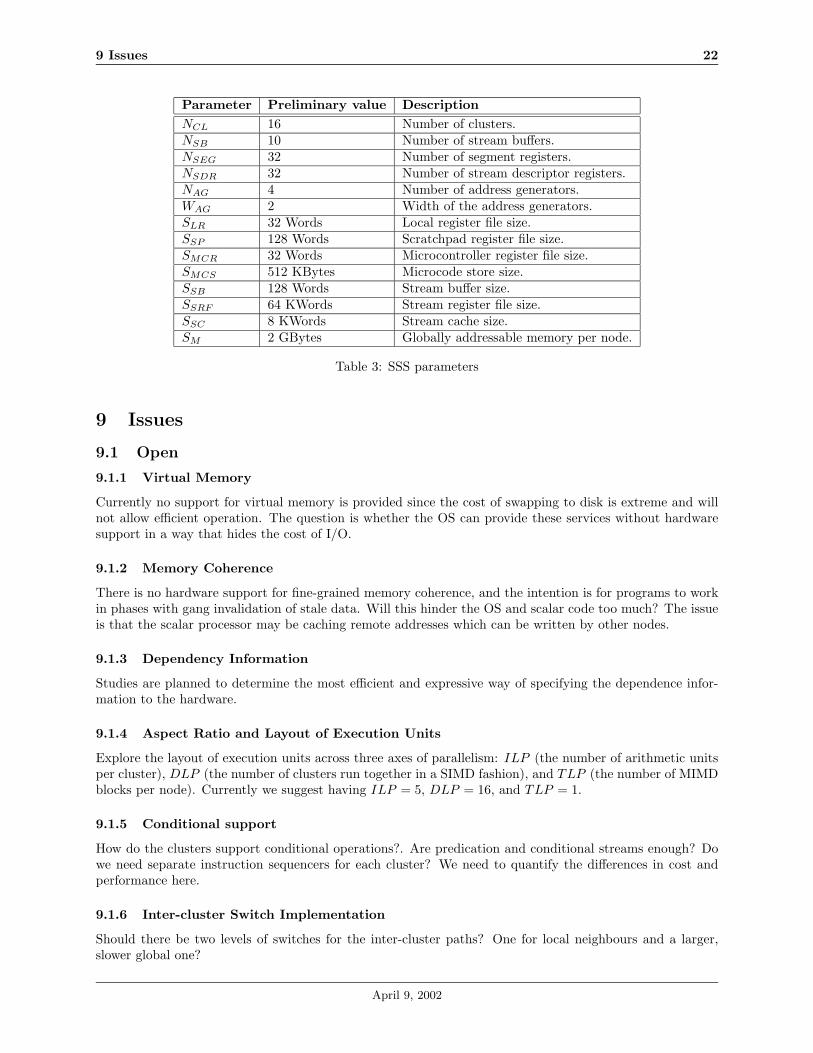
Table 3 lists the parameterized elements of the SSS architecture. Note that all words are 64-bits wide unlessotherwise specified.
April 9, 2002
9 Issues 22
Parameter Preliminary value DescriptionNCL 16 Number of clusters.NSB 10 Number of stream buffers.NSEG 32 Number of segment registers.NSDR 32 Number of stream descriptor registers.NAG 4 Number of address generators.WAG 2 Width of the address generators.SLR 32 Words Local register file size.SSP 128 Words Scratchpad register file size.SMCR 32 Words Microcontroller register file size.SMCS 512 KBytes Microcode store size.SSB 128 Words Stream buffer size.SSRF 64 KWords Stream register file size.SSC 8 KWords Stream cache size.SM 2 GBytes Globally addressable memory per node.
Table 3: SSS parameters
9 Issues
9.1 Open
9.1.1 Virtual Memory
Currently no support for virtual memory is provided since the cost of swapping to disk is extreme and willnot allow efficient operation. The question is whether the OS can provide these services without hardwaresupport in a way that hides the cost of I/O.
9.1.2 Memory Coherence
There is no hardware support for fine-grained memory coherence, and the intention is for programs to workin phases with gang invalidation of stale data. Will this hinder the OS and scalar code too much? The issueis that the scalar processor may be caching remote addresses which can be written by other nodes.
9.1.3 Dependency Information
Studies are planned to determine the most efficient and expressive way of specifying the dependence infor-mation to the hardware.
9.1.4 Aspect Ratio and Layout of Execution Units
Explore the layout of execution units across three axes of parallelism: ILP (the number of arithmetic unitsper cluster), DLP (the number of clusters run together in a SIMD fashion), and TLP (the number of MIMDblocks per node). Currently we suggest having ILP = 5, DLP = 16, and TLP = 1.
9.1.5 Conditional support
How do the clusters support conditional operations?. Are predication and conditional streams enough? Dowe need separate instruction sequencers for each cluster? We need to quantify the differences in cost andperformance here.
9.1.6 Inter-cluster Switch Implementation
Should there be two levels of switches for the inter-cluster paths? One for local neighbours and a larger,slower global one?
April 9, 2002

9.2 Closed 23
9.1.7 Register File Organization
Is the two ported local register file still the optimal design point as it was in Imagine?
9.1.8 Integer Unit in Clusters
Should the clusters contain an integer unit in addition to the double precision floating point units? Some ofthe operations required for conditional support will not require floating point arithmetic.
9.1.9 Memory Locking
Need to spec out how the memory system will support locking of addresses. Perhaps a small table in eachnode of physical addresses in that node which are locked? This is useful for fetch-and-op, and maybe forother things too.
9.1.10 Multidimensional Strides
Brook supports multidiminsional strides as well as stream grouping (specifying which elements of one streamare grouped to form a single element of a new stream), and Ian said that many applications will make useof at least the multidimensional strides. Should the SSS hardware support more than the one dimensionalstrided access currently specified? How about the grouping?
9.2 Closed
9.2.1 SRF, SB, SC
Determine the arrangement of these three elements of the machine state. Do we allow the clusters to directlyreference the SRF or only via the SBs? Can the clusters reference the SC or do they need to generate anindex stream and then have the AGs reference the SC?
Resolution: The blocks are arranged as illustrated in the block diagram.
9.2.2 Stream Cache
Do we want the cache to be integrated with the SRF so we can fetch blocks from the cache into the SBs?Or alternatively, do we want the cache on the far side of the AGs so that the cache just filters memoryreferences? Probably the latter, but we need to quantify the differences.
Resolution: Cache is on far side of AGs.
9.2.3 Parallelism Within the Node
We need to quantify the advantages of having the clusters operate in parallel on adjacent elements of astream as opposed to subdividing the stream and having each cluster operate on a contiguous substream.Having the clusters work on adjacent elements incurs more inter-cluster communication but enables efficientstream access.
Resolution: This is a software issue, but we need to ensure that the provides this flexibility to the software.
9.2.4 Fetch-and-Op
Is it efficient for the scalar processor to interrupt the program it is running to process a fetch-and-op requestfrom a remote node? There would be overhead related to it’s pipeline and also to message handling ingeneral. Might it be better in the case of a large user-defined operation to not have this feature and justhave the remote node do a fetch, operate on it locally, and then write the copy back? Is the atomicity ofthis operation an important feature?
April 9, 2002
9.2 Closed 24
Resolution: There will be fetch-and-op, but the exact specs for this are yet to be done. The memorysystem should support some level of memory locking, guaranteeing atomicity.
9.2.5 Inter-cluster Switch Placement
Can the inter-cluster switch also route information between the SRF and the clusters? Is this kind of routingneeded to implement conditional streams?
Resolution: The switch will not route data between the SRF and the clusters. Data can be communi-cated between clusters; this is sufficient for the implementation of conditional streams.
9.2.6 Memory Segment Sizes
The specification currently in this document is that a segment must be of length 2k bytes in each node (andhence is of size n ∗ 2k bytes total for a segment over n nodes), and the base physical address of the segmentmemory in each node must be a multiple of the segment size (2k). Is this correct? If so, it seems that a lotof memory will be wasted between segments. What is the problem with having arbitrary segments? Thatis, both the segment size and segment base address are only restricted to being a multiple of 8 bytes (1 word).
Resolution: The segment size must be a power of 2, but the segment base address is only restrictedto being word aligned.
9.2.7 Number of Stream Buffers
How many stream buffers should be specified in the SSS parameters table?
Resolution: Tentatively choose 10.
9.2.8 Support for Debugging of Software
Should the hardware support breakpointing etc. to enable user software to be debugged more easily?
Resolution: The scalar processor will support breakpointing (e.g. MIPS), but this won’t effect the otherblocks, which will keep on executing despite the scalar processor pausing.
9.2.9 General Purpose Timers
A small question: Would it be useful to have a set of general purpose timers in the hardware? From thescalar program’s perspective, these would be registers that it could write with a number, and the value woulddecrement by 1 every clock cycle, interrupting the processor once it reached 0. The timers would enable theprogram to have a real-time component; does this matter at all?
Resolution: The scalar processor (e.g. MIPS) will most likely already implement some timers.
9.2.10 Multicasting
Can packets be milticast over the network? Specifically, can a node send a signal of some kind to a set ofother nodes?
Resolution: No, the network won’t allow the processor to specify multiple destinations for a given sig-nal.
April 9, 2002
REFERENCES 25
9.2.11 SIMD Floaing Point Units
Should the floating point units (adder, multiplier, and divide/square-root) in each cluster be able to operateas both 64-bit units as well as paired 32-bit units? In the latter mode, each 64-bit operand would be split intotwo 32-bit operands, and the floating point operation would be performed on each pair of 32-bit operandsin parallel. If this were used, the clusters may also need a hardware floating point truncation/packingand padding/unpacking block, as the one program may use some single-precision kernels and some double-precision kernels.
Resolution: This could be a performance-improving feature, but it would add to the complexity with-out contributing to research, so will not be included in the SSS.
9.2.12 L2 Cache
Should the processor-memory interface be an L2 cache? Or should the interface simply handle the byte/wordalignment issue?
Resolution: Yes, the PMI will be the processor’s L2 cache.
9.2.13 SRF Random Access
Will random mode accesses to the SRF be supported? Will there be a mini-memory access scheduler betweenthe SBs and the SRF to maximize the SRF bandwidth during random mode transfers?
Resolution: Random access to the SRF is not supported.
References
[1] B. Khailany, B. Dally, et al., “Imagine: Media Processing with Streams”, IEEE Micro, March-April 2001,pp. 35-46.
[2] B. Dally, P. Hanrahan, R. Fedkiw, “A Streaming Supercomputer”, September 2001.
[3] U. Kapasi, B. Dally, et al. “Efficient Conditional Operations for Data-parallel Architectures”, Proceedingsof the 33rd Annual International Symposium on Microarchitecture.
[4] B. Dally, S. Rixner, et al., “The Imagine Instruction Set Architecture”, June 2001.
[5] (Peter Mattson’s PhD)
[6] (Ian Buck’s Brook document)
[7] (Ben Serebrin’s cache coherency memo)
[8] (Document describing Flit Reservation Flow Control)
April 9, 2002


![· strawman:classes_with_trait_composition [ES Wiki] [[strawman: classes_with_trait_composition]] ES Wiki Trace: » strawman » completion_reform » proxy_drop_receiver ...](https://static.fdocuments.us/doc/165x107/5f5adf2cd54bbc484256e8da/strawmanclasseswithtraitcomposition-es-wiki-strawman-classeswithtraitcomposition.jpg)