SSGC - cityofbuckley.com3F3908CB-99FA-4EBD-A0DE... · Geotechnical Engineering Report SSGC Division...
24
Transcript of SSGC - cityofbuckley.com3F3908CB-99FA-4EBD-A0DE... · Geotechnical Engineering Report SSGC Division...

Geotechnical Engineering Report SSGC
Division Street Residential Development
South Division Street
Buckley, Washington
SSGC Project No. 17015
March 21, 2017
2
Soil Conditions
Topsoil was below the surface and ranged from about 6 inches to 1 foot at the test pit locations.
Native soil below the topsoil in test pits TP-1, TP-2, TP-4 and TP-6 consisted of silt with clay,
sand, and gravel. This soil was in a soft condition and extended to depths between about 2 and 3
feet. Silty sand with gravel, cobbles and occasional boulders was below this upper silt in these
test pits and below the topsoil in the remainder of the test pits. This soil was loose to medium
dense (with depth) and continued to the termination depth of the test pits.
Groundwater Conditions
Seepage was observed in all of the test pits (except TP-9) at the time of excavation. Seepage was
typically observed within the upper two feet of the surface. Additionally, mottling of the upper
native soils suggests wet soil conditions during portions of the year. Another layer of seepage
(groundwater) was observed at a depth of about 8 feet in test pit TP- 6 in the southeastern portion
of the site. Deeper seepage zones were not observed in the remaining test pits. Localized
standing surface water was observed at the time of our fieldwork, particularly in the southern
portion of the property.
Geologic Setting
The USDA Soil Conservation Service Soil Map of Pierce County, Washington (1979) maps soils
on the property as Buckley gravelly silt loam. This soil reportedly formed in Osceola mud flow
deposits. Permeability is reportedly slow, and the erosion hazard is low. Native soils in the test
pits appeared to conform to the mapped soil type.
GEOTECHNICAL DESIGN CONSIDERATIONS
The planned development is considered feasible based on observed soil conditions in the test pits
completed. Native medium dense soils can provide suitable bearing for foundations, slab-on-grade floors,
and pavements. However, observed shallow seepage suggests earthwork activities may be difficult
during the wetter seasons of the year.
Recommendations presented in the following sections should be considered general and may require
modifications when earthwork begins. They are based upon the subsurface conditions observed in the test
pits and the assumption that finish site grades will be similar to existing grades. It should be noted that
subsurface conditions across the site may vary from those depicted on the exploration logs and can
change with time. Therefore, proper site preparation will depend upon the weather and soil conditions
encountered at the time of construction. We recommend SSGC review final plans and further assess
subgrade conditions at the time of construction.

Geotechnical Engineering Report SSGC
Division Street Residential Development
South Division Street
Buckley, Washington
SSGC Project No. 17015
March 21, 2017
3
General Site Preparation
Site grading and earthwork should include procedures to control surface water runoff. Grading the site
without adequate drainage control measures may negatively impact site soils, resulting in increased export
of impacted soil and import of fill materials, thereby potentially increasing the cost of the earthwork and
subgrade preparation phases of the project.
Site grading should include removal (stripping) of topsoil and any fill (if encountered) in new building
and pavement areas. We estimate stripping depths will be on the order of 1 to 2 feet, but should be
expected to be locally deeper based on the time of year of construction. Subgrades should consist of firm
native soils following stripping.
General Subgrade Preparation
We recommend exposed subgrades in building and conventional pavement areas are proofrolled using a
large roller, loaded dump truck, or other mechanical equipment to assess subgrade conditions following
stripping. Proofrolling efforts should result in the upper 1 foot of subgrade soils achieving a compaction
level of at least 95 percent of the maximum dry density (MDD) per the ASTM D1557 test method. Wet,
loose, or soft subgrades that cannot achieve this compaction level should be removed and replaced with
structural fill. A representative of SSGC should be present to assess subgrade conditions during
proofrolling.
Grading and Drainage
Positive drainage should be provided during construction and maintained throughout the life of the
development. Allowing surface water into cut or fill areas, utility trenches, and building footprints should
be prevented.
Structural Fill Materials
The suitability of soil for use as structural fill will depend on the gradation and moisture content of the
soil when it is placed. Soils with higher fines content (soil fraction passing the U.S. No. 200 sieve) will
become sensitive with higher moisture content. It is often difficult to achieve adequate compaction if soil
moisture is outside of optimum ranges for soils that contain more than about 5 percent fines.
Site Soils: Topsoil is not considered suitable for structural fill due to organic materials. Existing
native site soils contain relatively high fines (silt and clay) and would generally not be considered
suitable for structural fill. It will be difficult to moisture condition (dry) these soils to optimum
moisture content. Optimum moisture is considered within about +/- 2 percent of the moisture
content required to achieve the maximum density per the ASTM D-1557 test method. If moisture

Geotechnical Engineering Report SSGC
Division Street Residential Development
South Division Street
Buckley, Washington
SSGC Project No. 17015
March 21, 2017
4
content is higher or lower than optimum, soils would need to be dried or wetted prior to
placement as structural fill.
Import Fill Materials: We recommend import structural fill placed during dry weather periods
consist of material which meets the specifications for Gravel Borrow as described in Section 9-
03.14(1) of the 2014 Washington State Department of Transportation (WSDOT) Specifications
for Road, Bridge, and Municipal Construction (Publication M 41-10). Gravel Borrow should be
protected from disturbance if exposed to wet conditions after placement.
During wet weather, or for backfill on wet subgrades, import soil suitable for compaction in
wetter conditions should be provided. Imported fill for use in wet conditions should generally
conform to specifications for Select Borrow as described in Section 9-03.14(2), or Crushed
Surfacing per Section 9-03.9(3) of the 2014 WSDOT M-41 manual, with the modification that a
maximum of 5 percent by weight shall pass the U.S. No. 200 sieve for these soil types.
It should be noted that structural fill placement and compaction is weather-dependent. Delays due
to inclement weather can occur, even when using select granular fill. We recommend site grading
and earthwork be scheduled for the drier months of the year. Structural fill should not consist of
frozen material.
Structural Fill Placement
We recommend structural fill is placed in lifts not exceeding about 10 to 12 inches in loose measure. It
may be necessary to adjust lift thickness based on site and fill conditions during placement and
compaction. Structural fill should be compacted to attain the recommended levels presented in Table 1,
Compaction Criteria. Structural fill should extend laterally out at least 5 feet from the edge of footings or
pavement areas and then at a maximum 2H:1V (Horizontal:Vertical) incline.
Table 1. Compaction Criteria
Fill Application Compaction Criteria*
Footing areas (below structures) 95 %
Upper 2 feet in pavement areas, slabs and sidewalks, and utility trenches 95 %
Below 2 feet in pavement areas, slabs and sidewalks, and utility trenches 92 %
Utility trenches or general fill in non-paved or -building areas 90 %
*Per the ASTM D 1557 test method.
Trench backfill within about 2 feet of utility lines should not be over-compacted to reduce the risk of
damage to the line. In some instances the top of the utility line may be within 2 feet of the surface.
Backfill in these circumstances should be compacted to a firm and unyielding condition.

Geotechnical Engineering Report SSGC
Division Street Residential Development
South Division Street
Buckley, Washington
SSGC Project No. 17015
March 21, 2017
5
We recommend fill procedures include maintaining grades that promote drainage and do not allow
ponding of water within the fill area. The contractor should protect compacted fill subgrades from
disturbance during wet weather. In the event of rain during structural fill placement, the exposed fill
surface should be allowed to dry prior to placement of additional fill. Alternatively, the wet soil can be
removed. We recommend consideration be given to protecting haul routes and other high traffic areas
with free-draining granular fill material (i.e. sand and gravel containing less than 5 percent fines) or
quarry spalls to reduce the potential for disturbance to the subgrade during inclement weather.
Earthwork Procedures
Conventional earthmoving equipment should be suitable for earthwork at this site. Earthwork may be
difficult during periods of wet weather or if elevated soil moisture is present. Excavated site soils may
not be suitable as structural fill depending on the soil moisture content and weather conditions at the time
of earthwork. If soils are stockpiled and wet weather is anticipated, the stockpile should be protected with
securely anchored plastic sheeting. If stockpiled soils become unusable, it may become necessary to
import clean, granular soils to complete wet weather site work.
Wet or disturbed subgrade soils should be over-excavated to expose firm, non-yielding, non-organic soils
and backfilled with compacted structural fill. We recommend the earthwork portion of this project be
completed during extended periods of dry weather. If earthwork is completed during the wet season
(typically late October through May) it may be necessary to take extra measures to protect subgrade soils.
If earthwork takes place during freezing conditions, we recommend the exposed subgrade be allowed to
thaw and is re-compacted prior to placing subsequent lifts of structural fill. Alternatively, the frozen soil
can be removed to unfrozen soil and replaced with structural fill.
The contractor is responsible for designing and constructing stable, temporary excavations (including
utility trenches) as required to maintain stability of excavation sides and bottoms. Excavations should be
sloped or shored in the interest of safety following local and federal regulations, including current OSHA
excavation and trench safety standards. Temporary excavation cuts should be sloped at inclinations of
1.5H:1V (Horizontal:Vertical) or flatter, unless the contractor can demonstrate the safety of steeper
inclinations. The presence of shallow seepage may impact trench sidewall stability and require shoring
for deeper excavations.
A qualified geotechnical engineer should be retained during the construction phase of the project to
observe earthwork operations and to perform necessary tests and observations during subgrade
preparation, placement and compaction of structural fill, and backfilling of excavations.

Geotechnical Engineering Report SSGC
Division Street Residential Development
South Division Street
Buckley, Washington
SSGC Project No. 17015
March 21, 2017
6
Foundations
Foundations can be placed on native subgrade soil or on a zone of structural fill over prepared subgrades
as described in this report. Foundations should not be placed on saturated or soft subgrades. The
following recommendations have been prepared for conventional spread footing foundations.
Bearing Capacity (net allowable): 1,500 pounds per square foot (psf) for footings
supported firm native soils or structural fill over native
subgrades prepared as described in this report.
Footing Width (Minimum): 18 inches (Strip)
24 inches (Column)
Embedment Depth (Minimum): 18 inches (Exterior)
12 inches (Interior)
Settlement: Total: < 1 inch
Differential: < 1/2 inch (over 30 feet)
Allowable Lateral Passive Resistance: 300 psf/ft* (below 18 inches)
Allowable Coefficient of Friction: 0.35*
*These values include a factor of safety of approximately 1.5.
The net allowable bearing pressures presented above may be increased by one-third to resist transient,
dynamic loads such as wind or seismic forces. Lateral resistance to footings should be ignored in the
upper 12-inches from exterior finish grade.
Foundation Construction Considerations
All foundation subgrades should be free of water and loose soil prior to placing concrete, and
should be prepared as recommended in this report. Concrete should be placed soon after
excavating and compaction to reduce disturbance to bearing soils. Should soils at foundation
level become excessively dry, disturbed, saturated, or frozen, the affected soil should be removed
prior to placing concrete. We recommend that SSGC observe all foundation subgrades prior to
placement of concrete.
Foundation Drainage
Ground surface adjacent foundations should be sloped away from the structure. We recommend
footing drains are installed around perimeter footings. Footing drains should include a minimum 4-
inch diameter perforated rigid plastic or metal drain line installed at the base of the footing. The
perforated drain lines should be connected to a tight line pipe that discharges to an approved storm

Geotechnical Engineering Report SSGC
Division Street Residential Development
South Division Street
Buckley, Washington
SSGC Project No. 17015
March 21, 2017
7
drain receptor. The drain line should be surrounded by a zone of clean, free-draining granular
material having less than 5 percent passing the No. 200 sieve or meeting the requirements of section
9-03.12(2) “Gravel Backfill for Walls” in the 2014 WSDOT Standard Specifications for Road,
Bridge, and Municipal Construction manual (M41-10). The free-draining aggregate zone should
be at least 12 inches wide and wrapped in filter fabric. The granular fill should extend to within 6
inches of final grade where it should be capped with compacted fill (or topsoil) containing sufficient
fines to reduce infiltration of surface water into the footing drains. Alternately, the ground surface
can be paved with asphalt or concrete. Cleanouts are recommended for maintenance of the drain
system.
On-Grade Floor Slabs
On-grade floor slabs should be placed on native soils or structural fill prepared as described in this report.
We recommend a modulus subgrade reaction of 150 pounds per square inch per inch (psi/in) for native
soils or compacted granular structural fill on native subgrades.
We recommend a capillary break is provided between the prepared subgrade and bottom of slab.
Capillary break material should be a minimum of 4 inches thick and consist of compacted clean, free-
draining, well graded coarse sand and gravel. The capillary break material should contain less than 5
percent fines, based on that soil fraction passing the U.S. No. 4 sieve.
We recommend positive separations and/or isolation joints are provided between slabs and foundations,
and columns or utility lines to allow independent movement, where needed. Backfill in interior trenches
beneath slabs should be compacted in accordance with recommendations presented in this report.
A vapor retarder should be considered beneath concrete slabs that will be covered with moisture sensitive
or impervious coverings (such as tile, wood, etc.), or when the slab will support equipment or stored
materials sensitive to moisture. We recommend the slab designer refer to ACI 302 and/or ACI 360 for
procedures and limitations regarding the use and placement of vapor retarders.
Seismic Considerations
Seismic parameters and values in Table 2 are recommended based on the 2015 International Building
Code (IBC).

Geotechnical Engineering Report SSGC
Division Street Residential Development
South Division Street
Buckley, Washington
SSGC Project No. 17015
March 21, 2017
8
Table 2. Seismic Parameters
PARAMETER VALUE
2015 International Building Code (IBC)
Site Classification1 D
Site Latitude N 47.15243°
Site Longitude W 122.03008°
Ss Spectral Acceleration for a Short Period 1.184
S1 Spectral Acceleration for a 1-Second Period 0.444g
Fa Site Coefficient for a Short Period 1.026
Fv Site Coefficient for a 1-Second Period 1.556
1 Note: In general accordance with 2015 International Building Code, Section 1613.3.2 for risk categories
I,II,III. IBC Site Class is based on the specified characteristics of the upper 100 feet of the subsurface profile. Ss,
S1, Fa, and Fv values based on the USGS US Seismic Design Maps website using referenced site latitude and
longitude. The recommended seismic site class considers a stiff soil profile continues below the maximum
depth of the explorations and is based on the referenced maps in this report and other geotechnical information
in the area.
Liquefaction
Soil liquefaction is a condition where loose, typically granular soils located below the
groundwater surface lose strength during ground shaking, and is often associated with
earthquakes. The Pierce County “Potential Liquefaction and/or Dynamic Settlement Hazard
Area” map (dated 2004) does not show the site in a potential seismic hazard area. However, due
to the variability of Osceola mud flow deposits, localized liquefaction of native soils could
potentially occur resulting in some differential settlement. We estimate up to 2 (+/-) inches of
differential settlement could occur during a design level earthquake. This amount of movement
may cause cosmetic and slight structural damage, but should not impact the overall structural
integrity of single-story buildings.
Pavements
Subgrades for conventional pavement areas should be prepared as described in the “Subgrade
Preparation” section of this report. Subgrades below pavement sections should be graded or crowned to
promote drainage and not allow for ponding of water beneath the section. If drainage is not provided and
ponding occurs, the subgrade soils could become saturated, lose strength, and result in premature distress
to the pavement. In addition, the pavement surfacing should also be graded to promote drainage and
reduce the potential for ponding of water on the pavement surface.
We recommend a separation geotextile fabric (such as Mirafi 160N, or equivalent) is used on native
subgrade soils below planned pavement sections. This fabric should be placed on the prepared subgrade

Geotechnical Engineering Report SSGC
Division Street Residential Development
South Division Street
Buckley, Washington
SSGC Project No. 17015
March 21, 2017
9
prior to placement of granular pavement section fill. The purpose of the fabric is to maintain separation
of the coarser section fill materials and the moisture sensitive finer grained native soils, which will reduce
the risk of migration of the coarser fill into native soils. The fabric will improve the overall performance
of the section over time.
Pavement section designs have been prepared and are based on AASHTO design guidelines and the
following assumed design parameters:
15-year life span;
Estimated design life Equivalent Single Axle Loads (18 kips) of 925,000;
Estimated subgrade CBR of 6;
Terminal serviceability of 2.0; and,
Level of reliability 85 percent.
Minimum recommended pavement sections for conventional pavements are presented in Table 3. We
should be notified if actual traffic (ESAL) loads will be greater than those assumed to verify or modify
the pavement sections. Pavement sections in public right-of-ways should conform to Pierce County (or
City of Buckley) requirements for the road designation.
Table 3. Preliminary Pavement Sections
Traffic Area
Minimum Recommended Pavement Section Thickness (inches)
Asphalt Concrete
Surface1
Aggregate
Base Course3
Subbase
Aggregate4 Total
Driveways 2 4 6 8
Access Roads 4 6
8 18
Conventional Pavement Maintenance
The performance and lifespan of pavements can be significantly impacted by future maintenance.
The above pavement sections represent minimum recommended thicknesses and, as such, periodic
maintenance should be completed. Proper maintenance will slow the rate of pavement
deterioration, and will improve pavement performance and life. Preventive maintenance consists of
both localized maintenance (crack and joint sealing and patching) and global maintenance (surface
sealing). Added maintenance measures should be anticipated over the lifetime of the pavement
section if non-structural (undocumented) fill or topsoil is left in-place beneath pavement sections.
Geotechnical Engineering Report SSGC
Division Street Residential Development
South Division Street
Buckley, Washington
SSGC Project No. 17015
March 21, 2017
10
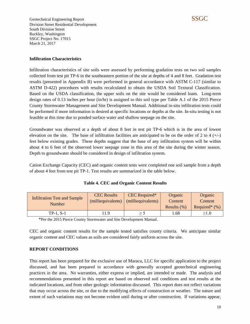
Infiltration Characteristics
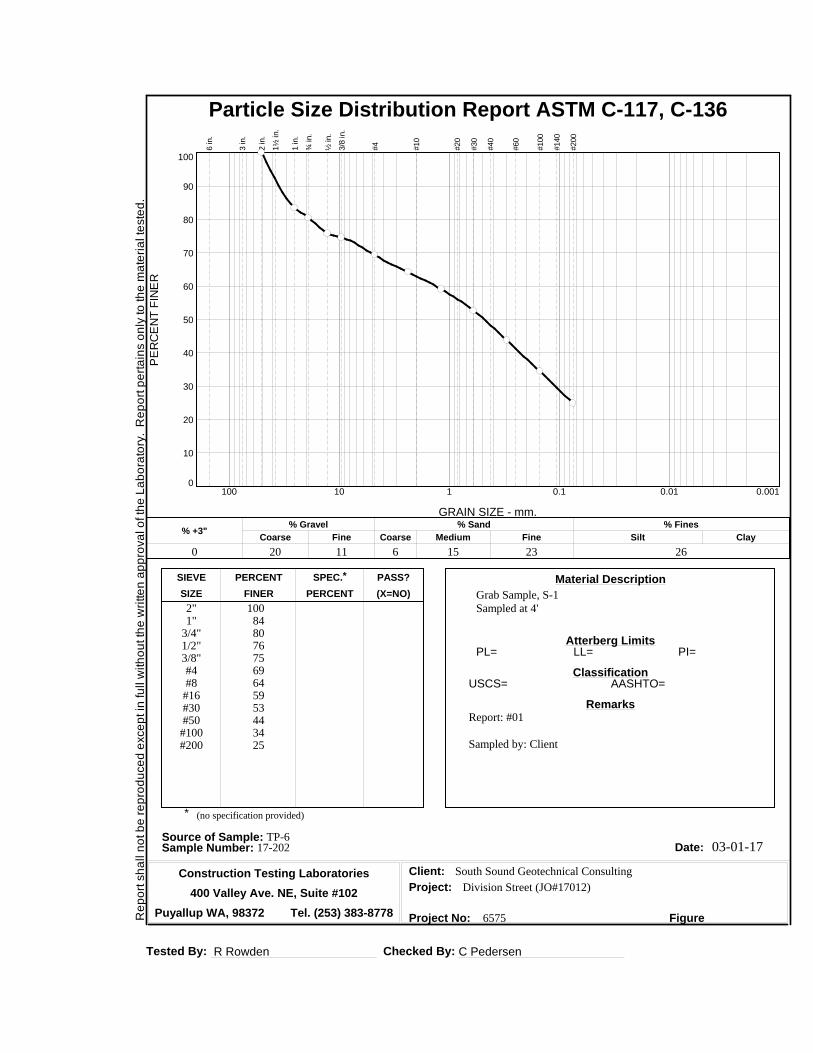
Infiltration characteristics of site soils were assessed by performing gradation tests on two soil samples
collected from test pit TP-6 in the southeastern portion of the site at depths of 4 and 8 feet. Gradation test
results (presented in Appendix B) were performed in general accordance with ASTM C-117 (similar to
ASTM D-422) procedures with results recalculated to obtain the USDA Soil Textural Classification.
Based on the USDA classification, the upper soils on the site would be considered loam. Long-term
design rates of 0.13 inches per hour (in/hr) is assigned to this soil type per Table A.1 of the 2015 Pierce
County Stormwater Management and Site Development Manual. Additional in-situ infiltration tests could
be performed if more information is desired at specific locations or depths at the site. In-situ testing is not
feasible at this time due to ponded surface water and shallow seepage on the site.
Groundwater was observed at a depth of about 8 feet in test pit TP-6 which is in the area of lowest
elevation on the site. The base of infiltration facilities are anticipated to be on the order of 2 to 4 (+/-)
feet below existing grades. These depths suggest that the base of any infiltration system will be within
about 4 to 6 feet of the observed lower seepage zone in this area of the site during the winter season.
Depth to groundwater should be considered in design of infiltration system.
Cation Exchange Capacity (CEC) and organic content tests were completed one soil sample from a depth
of about 4 feet from test pit TP-1. Test results are summarized in the table below.
Table 4. CEC and Organic Content Results
Infiltration Test and Sample
Number
CEC Results
(milliequivalents)
CEC Required*
(milliequivalents)
Organic
Content
Results (%)
Organic
Content
Required* (%)
TP-1, S-1 11.9 ≥ 5 1.68 ≥1.0
*Per the 2015 Pierce County Stormwater and Site Development Manual.
CEC and organic content results for the sample tested satisfies county criteria. We anticipate similar
organic content and CEC values as soils are considered fairly uniform across the site.
REPORT CONDITIONS
This report has been prepared for the exclusive use of Maracu, LLC for specific application to the project
discussed, and has been prepared in accordance with generally accepted geotechnical engineering
practices in the area. No warranties, either express or implied, are intended or made. The analysis and
recommendations presented in this report are based on observed soil conditions and test results at the
indicated locations, and from other geologic information discussed. This report does not reflect variations
that may occur across the site, or due to the modifying effects of construction or weather. The nature and
extent of such variations may not become evident until during or after construction. If variations appear,


N
South Sound Geotechnical Consulting P.O. Box 39500
Lakewood, WA 98496
(253) 973-0515
Figure 1 – Exploration Plan
Division Street Residential Development
Buckley, WA
SSGC Project #17012
Approximate Test Pit Location
PIT - 1
TP - 1
TP-1
TP-1
Scale: NTS
Base map from Google Earth.
TP-3 TP-4 TP-2
Legend
TP-5
TP-9
TP-8
TP-7
TP-6

Geotechnical Engineering Report SSGC
Division Street Residential Development
South Division Street
Buckley, Washington
SSGC Project No. 17015
March 21, 2017
12
Appendix A
Field Exploration Procedures and Test Pit Logs

Geotechnical Engineering Report SSGC
Division Street Residential Development
South Division Street
Buckley, Washington
SSGC Project No. 17015
March 21, 2017
13
Field Exploration Procedures
Our field exploration for this project included nine test pits on March 1, 2017. The approximate locations
of the explorations are shown on Figure 1, Exploration Plan. The exploration locations were determined
by pacing from site features. Ground surface elevations referenced on the logs were inferred from Google
Earth. Test pit locations and elevations should be considered accurate only to the degree implied by the
means and methods used.
A client provided excavator dug the test pits. Soil samples were collected and stored in moisture tight
containers for further assessment. Explorations were backfilled with excavated soils and tamped when
completed. Please note that backfill in the explorations will likely settle with time. Backfill material
located in roads or building areas should be re-excavated and recompacted, or replaced with structural fill.
The following logs indicate the observed lithology of soils and other materials observed in the
explorations at the time of excavation. Where a soil contact was observed to be gradational, our log
indicates the average contact depth. Our logs also indicate the approximate depth to groundwater (where
observed at the time of excavation), along with sample numbers and approximate sample depths. Soil
descriptions on the logs are based on the Unified Soil Classification System.

Project: Division Street Plat SSGC Job # 17012 TEST PIT LOGS PAGE 1 OF 4
Location: S. Division Street, Buckley, WA
TEST PIT LOGS FIGURE A-1
South Sound Geotechnical Consulting TP-1 TO TP-6 Logged by: THR
Test Pit TP-1
Depth (feet)
Material Description
0 – 1
1 – 3
3 – 7
Topsoil
SILT with clay, sand and gravel: Soft, wet, light brown.
Silty SAND with gravel, cobbles and occasional boulder:
Loose to medium dense, wet to moist, mottled brown-gray.
(Sample S-1 @ 4 feet)
Test pit completed at approximately 7 feet on 3/1/17.
Seepage observed at about 2 feet at time of excavation.
Approximate surface elevation: 726 feet
Test Pit TP-2
Depth (feet)
Material Description
0 – 0.75
0.75 – 2
2 – 10
Topsoil
SILT with clay, sand and gravel: Soft, wet, light brown.
Silty SAND with gravel, cobbles and occasional boulder:
Loose to medium dense, wet to moist, mottled brown-gray.
Grades brown at about 7 feet.
Test pit completed at approximately 7.5 feet on 2/17/17.
Seepage observed at about 2 feet at time of excavation.
Approximate surface elevation: 726 feet
Test Pit TP-3
Depth (feet)
Material Description
0 – 1
1 – 7
Topsoil
Silty SAND with gravel, cobbles and occasional boulder:
Loose to medium dense, wet to moist, mottled brown-gray.
Test pit completed at approximately 6 feet on 3/1/17.
Seepage observed at about 2.5 feet at time of excavation.
Approximate surface elevation: 725 feet

Project: Division Street Plat SSGC Job # 17012 TEST PIT LOGS PAGE 2 OF 4
Location: S. Division Street, Buckley, WA
TEST PIT LOGS FIGURE A-1
South Sound Geotechnical Consulting TP-1 TO TP-6 Logged by: THR
Test Pit TP-4
Depth (feet)
Material Description
0 – 1
1 – 2
5 – 7
Topsoil
SILT with clay, sand and gravel: Soft, wet, light brown.
Silty SAND with gravel, cobbles and occasional boulder:
Loose to medium dense, wet to moist, mottled brown-gray.
Grades brown at about 3 feet.
Test pit completed at approximately 7 feet on 3/117.
Seepage observed at about 1.5 feet at time of excavation.
Approximate surface elevation: 724 feet
Test Pit TP-5
Depth (feet)
Material Description
0 – 0.5
0.5 – 7
Topsoil
Silty SAND with gravel, cobbles and occasional boulder:
Loose to medium dense, wet to moist, mottled brown-gray.
Grades brown at about 3 feet.
Test pit completed at approximately 7 feet on 3/1/17.
Seepage observed at about 2 feet at time of excavation.
Approximate surface elevation: 723 feet

Project: Division Street Plat SSGC Job # 17012 TEST PIT LOGS PAGE 3 OF 4
Location: S. Division Street, Buckley, WA
TEST PIT LOGS FIGURE A-1
South Sound Geotechnical Consulting TP-1 TO TP-6 Logged by: THR
Test Pit TP-6
Depth (feet)
Material Description
0 – 1
1 – 2
2 – 8
8 - 10
Topsoil
SILT with clay, sand and gravel: Soft, wet, light brown.
Silty SAND with gravel, cobbles and occasional boulder:
Loose to medium dense, wet to moist, mottled brown-gray.
(Sample S-1 @ 4 feet; S-2 @ 6 feet)
SAND with silt, gravel, and cobbles: Medium dense, wet,
gray. (Sample S-3 @ 8 feet)
Test pit completed at approximately 10 feet on 3/1/17.
Seepage observed at 1.5 feet, and groundwater at 8 feet at
time of excavation.
Approximate surface elevation: 722 feet
Test Pit TP-7
Depth (feet)
Material Description
0 – 0.5
0.5 – 7
Topsoil
Silty SAND with gravel, cobbles and occasional boulder:
Loose to medium dense, wet to moist, mottled brown-gray.
Grades brown at about 3 feet.
Test pit completed at approximately 7 feet on 3/1/17.
Seepage observed at about 1 foot at time of excavation.
Approximate surface elevation: 721 feet
Test Pit TP-8
Depth (feet)
Material Description
0 – 1
1 – 6
Topsoil
Silty SAND with gravel, cobbles and occasional boulder:
Loose to medium dense, wet to moist, mottled brown-gray.
Grades brown at about 3 feet.
Test pit completed at approximately 6 feet on 3/1/17.
Seepage observed at about 0.5 foot at time of excavation.
Approximate surface elevation: 722 feet

Project: Division Street Plat SSGC Job # 17012 TEST PIT LOGS PAGE 4 OF 4
Location: S. Division Street, Buckley, WA
TEST PIT LOGS FIGURE A-1
South Sound Geotechnical Consulting TP-1 TO TP-6 Logged by: THR
Test Pit TP-9
Depth (feet)
Material Description
0 – 0.5
0.5 – 7
Topsoil
Silty SAND with gravel, cobbles and occasional boulder:
Medium dense, moist, mottled brown-gray. Grades brown at
about 2.5 feet.
Test pit completed at approximately 7 feet on 3/1/17.
Seepage or groundwater not observed at time of excavation.
Approximate surface elevation: 722 feet

Geotechnical Engineering Report SSGC
Division Street Residential Development
South Division Street
Buckley, Washington
SSGC Project No. 17015
March 21, 2017
14
Appendix B
Laboratory Testing and Results

Geotechnical Engineering Report SSGC
Division Street Residential Development
South Division Street
Buckley, Washington
SSGC Project No. 17015
March 21, 2017
15
Laboratory Testing
Select soil samples were tested for grain size distribution (gradation) by Construction Testing
Laboratories (CTL) of Puyallup, Washington. Organic content and cation exchange capacity (CEC) by
Northwest Agricultural Consultants of Kennewick, Washington. Results of the laboratory testing are
included in this appendix.
Re
po
rt s
ha
ll n
ot b
e r
ep
rod
uce
d e
xce
pt in
fu
ll w
ith
ou
t th
e w
ritte
n a
pp
rova
l o
f th
e L
ab
ora
tory
. R
ep
ort
pe
rta
ins o
nly
to
th
e m
ate
ria
l te
ste
d.
Tested By: R Rowden Checked By: C Pedersen
Particle Size Distribution Report ASTM C-117, C-136
PE
RC
EN
T F
INE
R
0
10
20
30
40
50
60
70
80
90
100
GRAIN SIZE - mm.
0.0010.010.1110100
% +3"Coarse
% Gravel
Fine Coarse Medium
% Sand
Fine Silt
% Fines
Clay
0 20 11 6 15 23 26
6 in.
3 in.
2 in.
1½
in.
1 in.
¾ in.
½ in.
3/8
in.
#4
#10
#20
#30
#40
#60
#100
#140
#200
SIEVE PERCENT SPEC.* PASS?
SIZE FINER PERCENT (X=NO)
Material Description
Atterberg Limits
Classification
Remarks
Source of Sample: TP-6Sample Number: 17-202 Date:
Client:
Project:
Project No: Figure
Grab Sample, S-1Sampled at 4'2"
1"3/4"1/2"3/8"#4#8#16#30#50
#100#200
1008480767569645953443425
Report: #01
Sampled by: Client
South Sound Geotechnical Consulting
Division Street (JO#17012)
6575
PL= LL= PI=
USCS= AASHTO=
* (no specification provided)
03-01-17
Construction Testing Laboratories
400 Valley Ave. NE, Suite #102
Puyallup WA, 98372 Tel. (253) 383-8778

Re
po
rt s
ha
ll n
ot b
e r
ep
rod
uce
d e
xce
pt in
fu
ll w
ith
ou
t th
e w
ritte
n a
pp
rova
l o
f th
e L
ab
ora
tory
. R
ep
ort
pe
rta
ins o
nly
to
th
e m
ate
ria
l te
ste
d.
Tested By: R Rowden Checked By: C Pedersen
Particle Size Distribution Report ASTM C-117, C-136
PE
RC
EN
T F
INE
R
0
10
20
30
40
50
60
70
80
90
100
GRAIN SIZE - mm.
0.0010.010.1110100
% +3"Coarse
% Gravel
Fine Coarse Medium
% Sand
Fine Silt
% Fines
Clay
0 17 14 6 16 23 24
6 in.
3 in.
2 in.
1½
in.
1 in.
¾ in.
½ in.
3/8
in.
#4
#10
#20
#30
#40
#60
#100
#140
#200
SIEVE PERCENT SPEC.* PASS?
SIZE FINER PERCENT (X=NO)
Material Description
Atterberg Limits
Classification
Remarks
Source of Sample: TP-6Sample Number: 17-203 Date:
Client:
Project:
Project No: Figure
Grab Sample, S-3Sampled at 8'2"
1"3/4"1/2"3/8"#4#8#16#30#50
#100#200
1009683797569645852423324
Report: #02
Sampled by: Client
South Sound Geotechnical Consulting
Division Street (JO#17012)
6575
PL= LL= PI=
USCS= AASHTO=
* (no specification provided)
03-01-17
Construction Testing Laboratories
400 Valley Ave. NE, Suite #102
Puyallup WA, 98372 Tel. (253) 383-8778

2545 W Falls Avenue
Kennewick, WA 99336
509.783.7450
www.nwag.com
Sample ID Organic Matter Cation Exchange Capacity
TP-1, S-1 1.68% 11.9 meq/100g
Method ASTM D2974 EPA 9081
South Sound Geotechnical Consulting PO Box 39500 Lakewood, WA 98496
Report: 40647-1
Date: March 16, 2017
Project No: 17012
Project Name: Division Street

UNIFIED SOIL CLASSIFICATION SYSTEM
Criteria for Assigning Group Symbols and Group Names Using Laboratory TestsA Soil Classification
Group Symbol
Group NameB
Coarse Grained Soils
More than 50% retained
on No. 200 sieve
Gravels More than 50% of coarse fraction retained on No. 4 sieve
Clean Gravels Less than 5% finesC
Cu 4 and 1 Cc 3E GW Well-graded gravelF
Cu 4 and/or 1 Cc 3E GP Poorly graded gravelF
Gravels with Fines More than 12% finesC
Fines classify as ML or MH GM Silty gravelF,G, H
Fines classify as CL or CH GC Clayey gravelF,G,H
Sands 50% or more of coarse fraction passes No. 4 sieve
Clean Sands Less than 5% finesD
Cu 6 and 1 Cc 3E SW Well-graded sandI
Cu 6 and/or 1 Cc 3E SP Poorly graded sandI
Sands with Fines More than 12% finesD
Fines classify as ML or MH SM Silty sandG,H,I
Fines Classify as CL or CH SC Clayey sandG,H,I
Fine-Grained Soils 50% or more passes the No. 200 sieve
Silts and Clays Liquid limit less than 50
inorganic PI 7 and plots on or above “A” lineJ CL Lean clayK,L,M
PI 4 or plots below “A” lineJ ML SiltK,L,M
organic Liquid limit - oven dried 0.75 OL
Organic clayK,L,M,N
Liquid limit - not dried Organic siltK,L,M,O
Silts and Clays Liquid limit 50 or more
inorganic PI plots on or above “A” line CH Fat clayK,L,M
PI plots below “A” line MH Elastic SiltK,L,M
organic Liquid limit - oven dried 0.75 OH
Organic clayK,L,M,P
Liquid limit - not dried Organic siltK,L,M,Q
Highly organic soils Primarily organic matter, dark in color, and organic odor PT Peat
A Based on the material passing the 3-in. (75-mm) sieve
B If field sample contained cobbles or boulders, or both, add “with cobbles or boulders, or both” to group name.
C Gravels with 5 to 12% fines require dual symbols: GW-GM well-graded gravel with silt, GW-GC well-graded gravel with clay, GP-GM poorly graded gravel with silt, GP-GC poorly graded gravel with clay.
D Sands with 5 to 12% fines require dual symbols: SW-SM well-graded sand with silt, SW-SC well-graded sand with clay, SP-SM poorly graded sand with silt, SP-SC poorly graded sand with clay
E Cu = D60/D10 Cc =
6010
2
30
DxD
)(D
F If soil contains 15% sand, add “with sand” to group name.
G If fines classify as CL-ML, use dual symbol GC-GM, or SC-SM.
HIf fines are organic, add “with organic fines” to group name.
I If soil contains 15% gravel, add “with gravel” to group name.
J If Atterberg limits plot in shaded area, soil is a CL-ML, silty clay.
K If soil contains 15 to 29% plus No. 200, add “with sand” or “with gravel,” whichever is predominant.
L If soil contains 30% plus No. 200 predominantly sand, add “sandy” to group name.
M If soil contains 30% plus No. 200, predominantly gravel,
add “gravelly” to group name. N PI 4 and plots on or above “A” line.
O PI 4 or plots below “A” line.
P PI plots on or above “A” line.
Q PI plots below “A” line.