SSD Architecture Considerations for a Spectrum of Enterprise
30
SSD Architecture Considerations for a SSD Architecture Considerations for a Spectrum of Enterprise Applications Spectrum of Enterprise Applications Alan Fitzgerald, VP and CTO SMART Modular Technologies
Transcript of SSD Architecture Considerations for a Spectrum of Enterprise

SSD Architecture Considerations for a SSD Architecture Considerations for a Spectrum of Enterprise ApplicationsSpectrum of Enterprise Applications
Alan Fitzgerald, VP and CTOSMART Modular Technologies

Introduction
Today’s SSD delivers form-fit-function compatible solid-state memory replacements for hard disks
By offering an HDD plug-in replacement, the SSD serves a massive existing infrastructure• Physical size and mounting• Host interface connectivity• Feature set and software compatibility

Distributed Flash Controllers Drive New SSD Topologies
The opportunity today for SSDs in network RAID storage is to replace enterprise HDDs with high IOPS SSDs
Advancements in distributed flash controller topologies permit the optimization of flash packaging to improve performance, power, and storage density beyond the standard SSDs in HDD form factors

HDD Storage System AlternativeThis presentation illustrates a solid state storage system alternative to HDD-based RAID storage systems
Flash memory packaging offers better efficiency when not used in the HDD form factor
Advanced fabric connected flash controller technology brings advantages of provisioning, reliability, performance, availability, and low cost FRU management

HDD RAID Architecture
A network storage system comprises
• High speed network I/O to the host / network
• Large cache memory to increase IOPS by consolidating small block transfers
• Redundant HDD controllers, disk drives, and power supplies to ensure high system availability
• Hot swappable media where the HDD is the FRU (Field Replaceable Unit)

Typical RAID Implementation w/ 3.5-Inch HDD

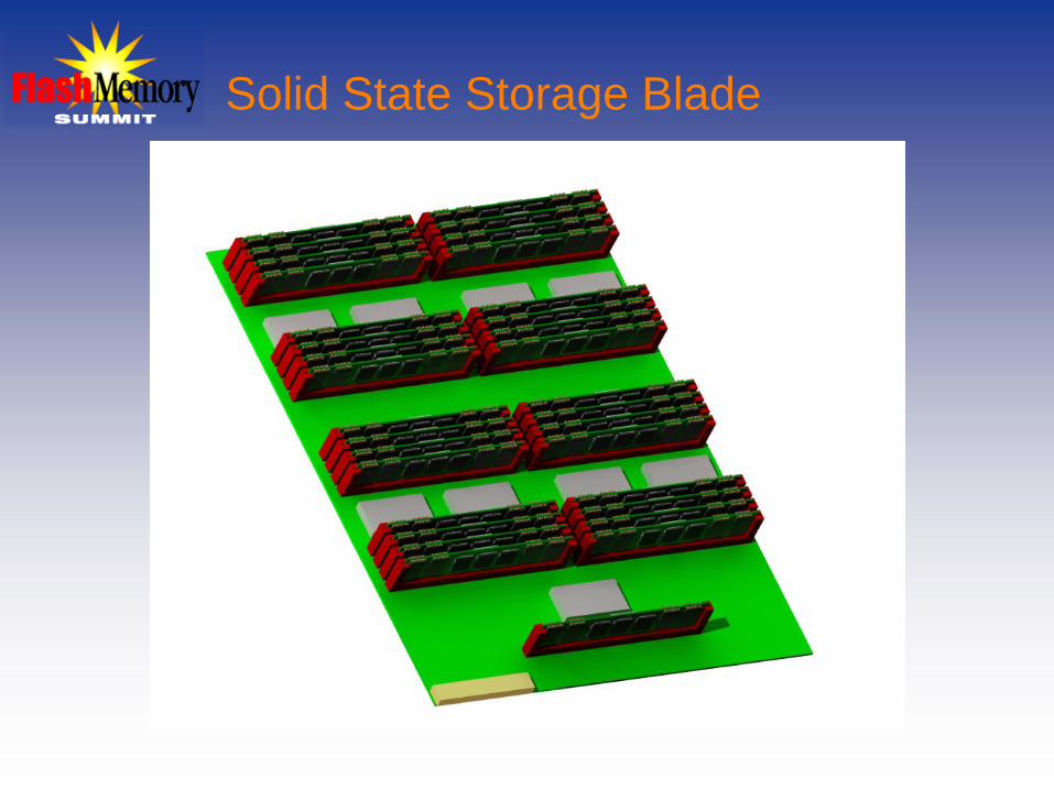
Solid State Storage Blade
System appropriate, high speed host front-end• Fibre Channel, SAS, Infiniband, PCIe
Multiple arrays of flash DIMMs• The DIMM becomes the FRU interconnected through a high-
speed flash fabric
Multiple hubs on the flash fabric provide connectivity between the DIMMS and the host front-end
System specific application configuration • Provisioning – Availability – Performance

Solid State Storage Blade
HostInterface
StorageApplication
FlashFabric
FlashHub
SE + FlashSE + Flash
SE + FlashSE + Flash
FlashHub
SE + FlashSE + Flash
SE + FlashSE + Flash
FlashHub
SE + FlashSE + Flash
SE + FlashSE + Flash
FlashHub
SE + FlashSE + Flash
SE + FlashSE + Flash
Dual-PortHost Network
InterfaceFlashFabric
FlashFabric
Solid State Storage Blade
DIMM Packaging Simplifies FRU and User Experience
This SSD topology takes advantage of high volume and low manufacturing costs of DIMM packaging
Configurable for redundancy (RAID) and hot swapping, the DIMM is field replaceable without system power down
The user (not the SSD manufacturer) determines overall capacity through the population and density of DIMMs

Flash FabricHigh Speed Serial Single or Multiple Lane• Typical serial similar to SATA and PCIe
Simplified Fabric Complexity Relative to• PCIe, SATA, SAS, IP
Low Latency• Optimize IOPS and Reduce Bottlenecks
Packets Optimized for Logical Flash Pages• Enforce Flash Media Efficiencies

Four DIMM Array – 1 TeraByte
FlashFabricHub
FlashCtrl
256 GB FlashMemory Array
FlashCtrl
256 GB FlashMemory Array
FlashCtrl
256 GB FlashMemory Array
FlashCtrl
256 GB FlashMemory Array
FlashFabric
FlashFabric

DIMM Characteristics
256 GByte Capacity2 Watts25 K / 20 K / ~20 K IOPS• 4 KByte random Read / Write / 2R:1W
300 MB/s / 200 MB/s• 128 KByte sequential Read / Write
78 IOPS per GByte 2R:1W• 20 K / 256
128 GBytes per Watt• 256 GBytes / 2

DIMM Storage Element

Distributed Flash Controllers Using High Speed Fabric
Communication over the Fabric • High speed single or multi-lane• Optimized command set for low power and low
latency
Each Controller Manages Arrays of Flash• Appears as a group of logical pages to the fabric• Translation to host logical blocks performed at the
Application Layer through a Logical Unit Manager

Flash Controller
Basic Flash Controller Responsibilities• Interface I/O supporting all of the external
connectivity, features and protocols
• Logical block to physical memory translation mapping and management
• Flash channel management with error detection, error correction, wear leveling, defect management, and the flash physical interface

DIMM Storage FRU
32 GBytesNAND Flash
32 GBytesNAND Flash
L2P Memory
FlashBus
Control
Payload ControllerCache
Memory
Flash Manager
FlashFabric
Flash Controller Memory Arrays
8 or More Arrays
FlashFabric
Interface

Storage Application Logical Unit Management
JBOD• Individual Disks with no Redundancy
RAID 0• Striped Disks with no Redundancy
RAID 1• Mirrored Disks with Redundancy
RAID 5• 3 or More Disks with Redundancy

Storage Front-End Host I/O – Application Layer – Flash I/O
Host NetworkFlashFabric
Host Interface:Infiniband
PCIeFC Dual Port
SAS Dual Port
FlashFabric I/O
StorageApplication
-Logical Unit Management
JBODRAID 0RAID 1RAID 5

Application Configured Solid State Storage Blade
HostInterface
StorageApplication
FlashFabric
FlashHub
FlashHub
FlashHub
FlashHub
Dual-PortHost Network
InterfaceFlashFabric
FlashFabric
SE + FlashSE + Flash
SE + FlashSE + Flash
SE + Flash
RAID 0
SE + Flash JBOD
SE + FlashSE + Flash RAID 1
SE + FlashSE + Flash
SE + FlashSE + Flash
SE + FlashSE + Flash
SE + FlashSE + Flash
RAID 5

JBOD on a Single DIM
256 GByte Capacity~20 K IOPS Random 2R:1W 4 KB>200 MBps Sequential (Fabric Saturated)High Availability• No Redundancy
128 GBytes per Watt• 256 GBytes / 2 W
78 IOPS per GB• 20 K / 256 GBytes
10,000 IOPS per Watt• 20 K / 2 W

RAID 0 Example

RAID 0 Across Five DIMS
1.25 TeraByte Capacity~100 K IOPS Random 2R:1W 4 KB>800 MBps Sequential High Availability• No Redundancy125 GBytes per Watt• 1,250 GB / 10 W
80 IOPS per GB• 100 K / 1,250 GB
10,000 IOPS per Watt• 100 K / 10 W

RAID 1 Example

RAID 1 Across Two DIMS
256 GByte Capacity~33 K IOPS Random 2R:1W 4 KB>400 / 200 MBps R/W SequentialHigh Availability• One DIMM per DIMM Pair Redundancy
64 GBytes per Watt• 256 GB / 4 W
129 IOPS per GByte• 33 K / 256 GB
8,250 IOPS per Watt• 33 K / 4 W

RAID 5 Example

RAID 5 Across Eight DIMS
1.75 TeraByte Capacity~140 K IOPS Random 2R:1W 4 KB>800 MBps SequentialHigh Availability• One DIMM Redundancy
109 GBytes per Watt• 1,750 GB / 16 W
80 IOPS per GB• 140 K / 1,750 GB
8,750 IOPS per Watt• 140 K / 16 W

Storage Application Performance Variations
IOPS MBps GB / W IOPS / G IOPS / W
JBOD 20K 300R / 200W 128 78 10,000
RAID 0 100K >800 125 80 10,000
RAID 1 33K 400R / 200W 64 129 8,250
RAID 5 140K >800 109 80 8,750

Wrap UpThere are many storage applications with a
corresponding number of SSD solutions ranging from 1.8” HDD replacements to PCIe plug-in cards.
This discussion represents one perspective among the many solid state storage solutions.
SMART is currently developing Fabric Attached flash controllers. Our first products based on this technology will be available in Q1 of 2010.

Thank You!Thank You!


![SGX-SSD: A Policy-based Versioning SSD with Intel SGX · Existing Solution: Versioning SSD[BVSSD, Systor12], [Project Almanac, Eurosys19] §Versioning SSD implements versioning system](https://static.fdocuments.us/doc/165x107/60ae19522c0a8f54c27ad581/sgx-ssd-a-policy-based-versioning-ssd-with-intel-sgx-existing-solution-versioning.jpg)