SS148.C.Piping Flexibility & Limitation of Thermal Stress ... · required to achieve adequately low...
28
Standard Specification No. 148 L:\Standard Specifications\SS148.C.Piping Flexibility & Limitation of Thermal Stress in Pipework.doc Page 1 of 28 Piping Flexibility and Limitation of Thermal Stress in Pipework 1.0 Introduction Designing refrigeration piping so that the arrangement is “flexible” reduces stresses due to mechanical and thermal movement. The mechanical loads on pipework due to its weight and contents are minimised by limiting the spans between each support as specified in Star Standard Specification No. 69. The purpose of this standard specification is to limit the loads on Star pipework and equipment nozzles due to thermal expansion and contraction caused by variations between the installation temperature and the working temperatures. The specification has been revised to include higher design pressure pipework and larger temperature differentials. 2.0 Thermal Stress Analysis Star Standard Specification No. 36 gives details of our standard method of pipe bracketing where the pipe and insulation (where applied) is mounted on sliding supports. The use of sliding supports allows the pipe to expand and contract freely without imposing additional strains. Figure 1 shows a simple piping arrangement for pipe AC with a right angled bend at B and the ends A and C fixed. Figure 2 shows a simple piping arrangement for pipe AC with a right angled bend at B, a valve between B and C and the ends A and C fixed. Figure 3 shows a simple piping arrangement for pipe AC with bend, a tee added before the bend and the ends A and C fixed. Any temperature variation causing a change in length of AB gives a deflection as shown with induced stresses at nodes C and B. The change in length AB for a given temperature variation for both carbon steel pipe (e.g. A106 Gr B and A333 Gr 6) and stainless steel pipe (e.g. 304, 304L, 316 and 316L) and for the various arrangements is given in Tables 1 to 51. The temperature change refers to the difference in temperature between the installation temperature and the working temperature. Tables 1 to 8 cover the case of 25.5 Bar G design pressure pipe, bend and valve as shown in Figure 2. Note the arrangement shown in Figure 1 is a simpler case to that shown in Figure 2 and is covered by Tables 1 to 8. Tables 9 to 16 cover the case of 25.5 Bar G design pressure where we have a tee before the bend as shown in Figure 3. A separate set of tables are shown for the tee arrangement in recognition of the additional restriction to bending in the header length associated with the header extending beyond the tee. All lengths are for the tee branch run and the header length up to the tee. In all cases the minimum straight length required in the perpendicular leg BC needed to maintain stress levels at B and C to within acceptable limits is also given. In the case of pipe, bend and valve, the valve runs are total straight pipe length required (excluding valve length) on that run of pipe, irrespective of valve position.
Transcript of SS148.C.Piping Flexibility & Limitation of Thermal Stress ... · required to achieve adequately low...
Standard Specification No. 148
L:\Standard Specifications\SS148.C.Piping Flexibility & Limitation of Thermal Stress in Pipework.doc Page 1 of 28
Piping Flexibility and Limitation of Thermal Stress in Pipework
1.0 Introduction Designing refrigeration piping so that the arrangement is “flexible” reduces stresses due to mechanical and thermal movement. The mechanical loads on pipework due to its weight and contents are minimised by limiting the spans between each support as specified in Star Standard Specification No. 69. The purpose of this standard specification is to limit the loads on Star pipework and equipment nozzles due to thermal expansion and contraction caused by variations between the installation temperature and the working temperatures. The specification has been revised to include higher design pressure pipework and larger temperature differentials.
2.0 Thermal Stress Analysis
Star Standard Specification No. 36 gives details of our standard method of pipe bracketing where the pipe and insulation (where applied) is mounted on sliding supports. The use of sliding supports allows the pipe to expand and contract freely without imposing additional strains. Figure 1 shows a simple piping arrangement for pipe AC with a right angled bend at B and the ends A and C fixed. Figure 2 shows a simple piping arrangement for pipe AC with a right angled bend at B, a valve between B and C and the ends A and C fixed. Figure 3 shows a simple piping arrangement for pipe AC with bend, a tee added before the bend and the ends A and C fixed. Any temperature variation causing a change in length of AB gives a deflection as shown with induced stresses at nodes C and B. The change in length AB for a given temperature variation for both carbon steel pipe (e.g. A106 Gr B and A333 Gr 6) and stainless steel pipe (e.g. 304, 304L, 316 and 316L) and for the various arrangements is given in Tables 1 to 51. The temperature change refers to the difference in temperature between the installation temperature and the working temperature. Tables 1 to 8 cover the case of 25.5 Bar G design pressure pipe, bend and valve as shown in Figure 2. Note the arrangement shown in Figure 1 is a simpler case to that shown in Figure 2 and is covered by Tables 1 to 8. Tables 9 to 16 cover the case of 25.5 Bar G design pressure where we have a tee before the bend as shown in Figure 3. A separate set of tables are shown for the tee arrangement in recognition of the additional restriction to bending in the header length associated with the header extending beyond the tee. All lengths are for the tee branch run and the header length up to the tee. In all cases the minimum straight length required in the perpendicular leg BC needed to maintain stress levels at B and C to within acceptable limits is also given. In the case of pipe, bend and valve, the valve runs are total straight pipe length required (excluding valve length) on that run of pipe, irrespective of valve position.

Standard Specification No. 148
L:\Standard Specifications\SS148.C.Piping Flexibility & Limitation of Thermal Stress in Pipework.doc Page 2 of 28
The tables give worst case minimum allowable distances. They are based on constrained pipework at either end. Our practice of utilising sliding brackets throughout will further limit the stress. The conservative design is reinforced by our use of materials which show a comparatively high ultimate tensile strength relative to their yield strength (to which the ASME B31.3 codes stress levels refer). For example:
Material ASTM Ultimate Tensile
Strength N/mm2
Yield Strength
N/mm2
Design Allowable Strength N/mm2
A106B and A333 Gr 6 414 241 138
304L 480 172 115
316L 480 172 115 Special consideration is needed for reverse cycle defrost lines. While practical experience (with no known pipe failure over 30 years) suggests that our piping designs are adequate, as an additional factor of safety, reverse cycle plant wet return pipe designs shall include for two times the minimum required length given in the tables. If there is any doubt about the applicability of the tables please refer to the Technical Department who can make special consideration of the particular design and can call on outside support from consultants with access to stress calculation software for complex systems. Special consideration has been given to vessel nozzle loadings. Tables 17 to 24 give the target required perpendicular lengths for BC in a 25.5 Bar G system where C is at a pressure vessel nozzle connection as shown in Figure 4. For tables 17 to 24, the run lengths provided are target lengths required to achieve adequately low nozzle loads with stress levels no greater than those allowed by ASME B31.3. As a guide we should aim for ±10% of the target length otherwise we should consider an expansion loop or introduce additional bends. Note that these tables for pressure vessel nozzle connections are only applicable if point A is fixed and are not applicable when point A is not fully constrained. Point C is also assumed to be fixed. In practice any degree of flexibility will add to the conservatism of the design. In some cases we may chose to introduce an expansion loop or include at least two pipe bends between the nozzle (or valve on the nozzle) and the plantroom wall. For example we can introduce additional flexibility by simply pointing the valve on the nozzle in a different direction before bending the pipe to return to the desired directions. Pipe arrangements that require greater thought and design considerations are clearly identified in the tables. In many arrangements the introduction of additional bends providing they are free of restraint can be a benefit. Tables 25 to 32 cover the case of Sch 40 pipe at 52 Bar G design pressure with Pipe and Bend. Tables 33 to 36 cover the case of Sch 40 pipes at 52 Bar G design pressure where C is at a pressure vessel nozzle connection. Tables 37 to 41 cover the case of Sch 40 pipes at 65 Bar G design pressure with pipe, bend and valve. Tables 42 to 46 cover the case of Sch 40 pipes at 65 Bar G design pressure with pipe, bend and tee. Tables 47 to 51 cover the case of Sch 40 pipes at 65 Bar G design pressure where C is at a pressure vessel nozzle connection.

Standard Specification No. 148
L:\Standard Specifications\SS148.C.Piping Flexibility & Limitation of Thermal Stress in Pipework.doc Page 3 of 28
Where the design includes piping with thinner wall thicknesses to those indicated in the tables, the tables will give conservative values. In specific piping flexibility checks where there are comparatively short changes of direction at positions away from the supports it is often convenient to analyse the piping system with the piping at these points assumed to be rigid and not requiring individual assessments. For these cases the short changes in direction can be ignored. The support of vertical runs of pipe (over 5 metres long) shall be given special consideration to ensure that the weight of pipe and contents are evenly distributed across the adjacent support brackets. The use of variable spring supports and hinges may be used to balance the gravitational load of vertical sections of pipe while allowing for thermal movement.
2.1 Ideas Report The tables are taken from Ideas Report No’s. 2004/026/1 and 2012/019/001.
2.1.1 The work involved pipework analysis to ASME B31.3 piping code (2002 edition) and comparison of vessel nozzle loads to Industry Standard allowable limits (see Tables 52 and 53).
2.1.2 The Static Analysis work required analysis for standard operating condition loads, i.e. weight,
pressure and temperature ranges of 40K, 60K, 80K, 100K and 120K. Pressures of –1 Bar G, 25.5 Bar G, 52 Bar G and 65 Bar G have been used to encompass the majority of static pressure scenarios. The effects of environmental loads were not considered. Sources of dynamic load were not considered. The effects of attached systems, thermal growths at nozzles, stress reduction factors for longitudinal seam welds, etc were not considered. Major assumptions are detailed in section 2.1.5.
2.1.3 The pipe stress package used was the fully validated CAESAR II Finite Element Package. 2.1.4 The force displacement relations for each structural member are considered linear, with CAESAR II
adding displacements. Displacements must be small enough to be added without affecting the accuracy of the analysis and calculations. CAESAR II linearises all non-linearities such as supports with gaps and friction. CAESAR II does not have material non-linear capabilities and as such calculates all stress levels as linear elastic. It is standard practice, where applicable, to ensure all primary stresses remain below material yield. With these parameters in mind, the piping systems were modelled with the following boundary conditions. Referring to Figures 1 to 4, Nodes A and C are taken rigidly fixed i.e. anchored. Any effects of attached pipework have been ignored in this study as it has been assumed that any attached pipework has minimal load/stress implications on the results and that the combination of a rigidly anchored termination point and a factor of safety in the stress levels gives a conservative design.
2.1.5 Assumptions 2.1.5.1 Valves
Valves are modelled as rigid elements with their weights added to the model. Valves are treated as rigid elements. All valves are butt welded.
Standard Specification No. 148
L:\Standard Specifications\SS148.C.Piping Flexibility & Limitation of Thermal Stress in Pipework.doc Page 4 of 28
2.1.5.2 General Assumptions & Omissions from Analysis
- Material is isotropic and homogeneous. - Small strain linear elastic theory applied. - All butt welds are carried out in accordance with ASME B31.3, therefore residual
strains are not considered. - Residual strains due to branch welds are not considered. - Supporting structures do not deflect. - Vessel nozzles do not deflect. - Attached pipework beyond that modelled is sufficiently flexible to not induce
excessive movements or loads on the pipework being considered. - For the tee models, the tee component is assessed as a forged, butt welded fitting. - The number of Operating Cycles in the life of the plant is less than 1 per day for 20
years. - No environmental loads applied. - No excessive movements/loads on valve bodies. - No dynamic loads - Fatigue aspects not considered. - Static coefficient of friction, µ = 0.3 unless otherwise specified - No sources of resonance in piping systems. - Buckling concerns due to the negative internal pressure are not considered. Sound
engineering practise with regard to this aspect of piping system layout and design is assumed.
- Corrosion allowance taken to be 0 mm. - Mill tolerance of ±12.5%. - Springs are not used to reduced nozzle loads. - Effects of reducers and reducing tees not included. - Effect of insulation is negligible. - Fluid density up to and including 1.1 SG. - Mass effect of different types of valve is negligible, modelled for effect of rigidity
rather than mass. - Effects of stress raisers and welded attachments are not included. - Transportation and lift loads are not considered. - The pipe support design follows the guidelines set out in Star SS 69 which gives
maximum permitted support spans. U bolt supports shall not be fitted within five pipe diameters to a bend.
2.1.6 Analysis Code & Load Cases 2.1.6.1 Analysis Code is ASME B31.3 Piping Code 2002 Ed
Full details of the load cases and stress calculations together with the allowable limits for analysis guidance rules and validation checks are given in the Ideas Report.

Standard Specification No. 148
L:\Standard Specifications\SS148.C.Piping Flexibility & Limitation of Thermal Stress in Pipework.doc Page 5 of 28
3.0 Guidelines for the Selection of Critical Lines
A pipeline is defined as critical and requiring checks against the tables in this standard specification if it falls into any of the following categories (categories have been defined with reference to piping design guide NORSOK Standard L-002 where applicable to refrigeration and heat pump systems):
(a) Any carbon or stainless steel line 150NB and above if it is working at 40K or more
from its installation temperature or 80NB and above if it is working at 60K or more from its installation temperature. The following are considered to have sufficient inherent flexibility:
• 65NB and below when the temperature is <60K from the installation temperature
• 125NB and below when the temperature is <40K from the installation temperature
• Copper pipes
(b) Any pipe connected to a vessel nozzle where there is only one bend between the vessel and the plantroom wall.
(c) Reverse cycle wet return defrost pipes 50NB and above to coolers where we can expect more than one defrost per day. For this particular case we will apply an additional factor of safety by doubling the minimum perpendicular length required by the table. Note, pipelines connected to reciprocating compressors and pumps and pipelines made from materials not listed in Star Standard Specification 105 shall be treated as special cases and referred to the Technical Department.
(d) Short, large diameter (150NB and above) pipes shall be given particular attention.
(e) Any carbon or stainless steel line 100NB and above if it has a straight length of greater than 50m.
(f) Any line falling into Category III according to the Pressure Equipment Directive (refer to table below):
Design Pressure Line Size Falling Into PED Category III
Group 1 Gas (e.g. R717, R290)
Group 2 Gas (e.g. R134a, R744)
17 Bar G ≥250NB ≥300NB 25 Bar G ≥150NB ≥300NB 40 Bar G ≥125NB ≥300NB 52 Bar G ≥125NB ≥300NB 65 Bar G ≥125NB ≥300NB Note that for group 2 liquids such as water or glycol, the highest PED Category is II.
For pipe sizes less than 150NB identified as critical per point a) or e) above,
reference should be made to the tables for 65 Bar G pipework (Tables 37 to 51) even for systems with a lower design pressure. This will give a conservative result.

Standard Specification No. 148
L:\Standard Specifications\SS148.C.Piping Flexibility & Limitation of Thermal Stress in Pipework.doc Page 6 of 28
4.0 Worked Examples
Example 1 Consider the arrangement shown in Figure 1 which is covered in tables 1 to 8. Consider a 12”NB (300NB) carbon steel pipe at 25.5 Bar G at 60K temperature change and with length AB of 50 metres. Table 4 gives the minimum required perpendicular length BC as 5.4 metres. So if BC is 5.4 metres or longer the pipework arrangement provides code compliant flexibility. Example 2
Consider the arrangement shown in Figure 5 which is effectively two copies of the shape shown in Figure 1 and covered in tables 1 to 8. ABC’ is the standard shape, C’CD is the same shape rotated by 180º. Point C’ is the same point as the anchor point location C in Figure 1. Note, arrangement ABCD is in the same two dimensional plane. If CD was perpendicular to AB (rather than parallel to it) BC would be in torsion so this comparison would not be valid or required. Consider a 14” NB (350 NB) carbon steel pipe at 25.5 Bar G and at 80K with length AB of 10 metres and a downstream length CD of 5 metres, the design considers minimum required lengths from Table 5. At 10 metres we get 3 metres minimum required length of BC’ and at 5 metres we get 2.1 metres minimum required length of C’C. This gives a total required length of 5.1 metres minimum BC, giving a conservative estimate of pipework required to provide code compliant flexibility. Example 3 Consider a 10” NB (250 NB) stainless steel pipe at 25.5 Bar G and at 40K with length AB of 10 metres and a downstream length CD of 20 metres, the design considers minimum required lengths from Table 3. At 10 metres we get 2.2 metres minimum required length of BC’ and at 20 metres we get 3.2 metres minimum required length of C’C.
This gives a total required length of 5.4 metres minimum BC.
Summary:
Example Pipe Size (NB)
Temp Range
(K) Material
Straight Length
AB
Straight Length
CD
Table 1 to 8
Minimum Length
BC’
Table 1 to 8
Minimum Length
C’C
Flexibility
Length Required
BC 1 300 60 CS 50 - 5.4 - 5.4
2 350 80 CS 10 5 3.0 2.1 5.1
3 250 40 SS 10 20 2.2 3.2 5.4
Rev Status Changes Originator A 06/05/05 First Issue DJH B 07/05/09 Minimum nozzle local tables 37 and 38
added DJH
B 07/05/09 All references to Barg changed to Bar G DJH B 07/05/09 Section 3.0 guidelines clarified DJH C 10/07/12 Section 3.0 guidelines clarified and Tables
37 to 51 added RWT

Standard Specification No. 148
L:\Standard Specifications\SS148.C.Piping Flexibility & Limitation of Thermal Stress in Pipework.doc Page 7 of 28
Temp. Change Between
Installation &
Operation K
Carbon Steel Pipe Stainless Steel Temp. Change Between
Installation &
Operation K
Carbon Steel Pipe Stainless Steel
Straight Length
AB
m
Change in AB due to temp. change
mm
BC min. required length
m
Change in AB due to temp. change
mm
BC min required length
m
Straight Length
AB
m
Change in AB due to temp. change
mm
BC min. required length
m
Change in AB due to temp. change
mm
BC min required length
m
40 2 0.6 0.4 1.0 0.6 40 2 0.5 0.5 1.0 0.9 60 2 1.0 0.6 1.7 0.9 60 2 1.0 0.7 1.7 1.2 80 2 1.5 0.9 3.0 1.2 80 2 1.5 1.0 2.4 1.4 40 5 1.8 0.9 2.9 1.2 40 5 1.8 1.0 2.9 1.4 60 5 2.8 1.1 4.5 1.5 60 5 2.9 1.3 4.4 1.7 80 5 4.0 1.4 6.0 1.8 80 5 3.9 1.6 6.0 2.0 40 10 3.9 1.3 6.1 1.8 40 10 3.8 1.5 6.0 2.0 60 10 5.9 1.7 9.2 2.2 60 10 6.0 1.9 9.1 2.5 80 10 8.2 2.0 12.3 2.5 80 10 8.1 2.3 12.2 3.0 40 15 6.0 1.6 9.3 2.2 40 15 5.9 1.8 9.3 2.5 60 15 9.0 2.0 14.0 2.7 60 15 10.4 2.4 13.9 3.0 80 15 12.4 2.5 18.6 3.2 80 15 15.0 2.9 18.5 3.5 40 20 8.0 1.8 12.5 2.6 40 20 8.0 2.1 12.4 3.0 60 20 12.2 2.4 18.8 3.3 60 20 12.3 2.8 18.6 3.6 80 20 16.6 3.0 24.9 3.7 80 20 16.5 3.5 24.8 4.2 40 50 20.3 3.0 31.5 4.1 40 50 20.2 3.4 31.4 4.6 60 50 30.6 3.9 47.3 5.2 60 50 30.9 4.5 47.0 5.8 80 50 41.7 4.8 62.7 6.3 80 50 41.6 5.5 62.5 7.0 40 100 40.8 4.5 63.0 6.0 40 100 40.6 5.0 62.9 6.8 60 100 62.1 5.8 94.2 7.3 60 100 61.9 6.5 94.0 8.2 80 100 83.4 7.0 125.3 8.5 80 100 83.3 8.0 125.2 9.5 40 200 79.6 6.0 124.0 8.5 40 200 79.5 7.0 123.8 9.4 60 200 122.3 8.0 186.3 10.3 60 200 122.1 9.0 186.2 12.2 80 200 164.9 10.0 248.7 12.0 80 200 164.7 11.0 248.6 15.0 40 300 116.0 8.0 182.5 12.0 40 300 115.5 9.0 182.1 14.0 60 300 180.0 11.5 276.1 16.5 60 300 179.6 14.0 275.7 20.0 80 300 244.0 15.0 369.7 21.0 80 300 243.8 19.0 369.4 26.0
SS 148 TABLE 1 - 6" Sch 40 @ 25.5 Bar G - PIPE, BEND & VALVE MINIMUM LENGTHS FOR FLEXIBILITY
SS 148 TABLE 2 - 8" Sch 20 @ 25.5 Bar G - PIPE, BEND & VALVE MINIMUM LENGTHS FOR FLEXIBILITY
Temp. Change Between
Installation &
Operation K
Carbon Steel Pipe Stainless Steel Temp. Change Between
Installation &
Operation K
Carbon Steel Pipe Stainless Steel
Straight Length
AB
m
Change in AB due to temp. change
mm
BC min. required length
m
Change in AB due to temp. change
mm
BC min required length
m
Straight Length
AB
m
Change in AB due to temp. change
mm
BC min. required length
m
Change in AB due to temp. change
mm
BC min required length
m
40 2 0.5 0.5 1.0 1.0 40 2 0.5 0.6 1.0 1.1 60 2 1.0 0.8 1.7 1.3 60 2 1.0 1.0 1.7 1.4 80 2 1.5 1.2 2.4 1.5 80 2 1.5 1.3 2.4 1.6 40 5 1.7 1.0 2.8 1.6 40 5 1.7 1.1 2.8 1.7 60 5 2.8 1.5 4.4 2.1 60 5 2.7 1.6 4.4 2.2 80 5 3.9 1.9 6.0 2.5 80 5 3.7 2.0 6.0 2.6 40 10 3.7 1.6 6.0 2.2 40 10 3.7 1.7 5.9 2.4 60 10 5.9 2.1 9.1 2.9 60 10 5.8 2.3 9.0 3.1 80 10 8.0 2.6 12.2 3.5 80 10 7.9 2.8 12.1 3.7 40 15 5.8 2.0 9.2 2.7 40 15 5.7 2.1 9.1 3.0 60 15 9.0 2.6 13.8 3.4 60 15 8.9 2.8 13.7 3.8 80 15 12.2 3.2 18.4 4.0 80 15 12.2 3.5 18.3 4.5 40 20 7.9 2.3 12.3 3.2 40 20 7.8 2.5 12.3 3.5 60 20 12.2 3.0 18.5 3.9 60 20 12.1 3.3 18.4 4.3 80 20 16.4 3.7 24.7 4.6 80 20 16.4 4.0 24.5 5.0 40 50 20.1 3.8 31.4 5.4 40 50 20.1 4.3 31.2 5.7 60 50 30.8 4.9 46.9 6.4 60 50 30.6 5.4 46.7 6.9 80 50 41.5 5.9 62.4 7.4 80 50 41.1 6.5 62.2 8.0 40 100 40.4 5.4 62.7 7.2 40 100 40.3 5.9 62.6 8.0 60 100 61.8 7.0 93.8 8.9 60 100 61.6 7.5 93.7 9.8 80 100 83.1 8.5 125.0 10.5 80 100 82.9 9.0 124.8 11.5 40 200 79.1 7.5 123.6 10.4 40 200 79.1 8.5 123.5 11.5 60 200 121.8 10.0 186.1 14.2 60 200 121.8 11.0 186.0 15.8 80 200 164.6 12.4 248.5 18.0 80 200 164.4 13.5 248.4 20.0 40 300 115.3 10.0 182.0 16.0 40 300 115.2 11.0 181.8 17.0 60 300 179.5 15.5 275.6 22.5 60 300 179.2 16.5 275.5 24.5 80 300 243.6 21.0 369.1 29.0 80 300 243.2 22.0 369.1 32.0
SS 148 TABLE 3 - 10" Sch 20 @ 25.5 Bar G - PIPE, BEND & VALVE MINIMUM LENGTHS FOR FLEXIBILITY
SS 148 TABLE 4 - 12" Sch 20 @ 25.5 Bar G - PIPE, BEND & VALVE MINIMUM LENGTHS FOR FLEXIBILITY

Standard Specification No. 148
L:\Standard Specifications\SS148.C.Piping Flexibility & Limitation of Thermal Stress in Pipework.doc Page 8 of 28
Temp. Change Between
Installation &
Operation K
Carbon Steel Pipe Stainless Steel Temp. Change Between
Installation &
Operation K
Carbon Steel Pipe Stainless Steel
Straight Length
AB
m
Change in AB due to temp. change
mm
BC min. required length
m
Change in AB due to temp. change
mm
BC min required length
m
Straight Length
AB
m
Change in AB due to temp. change
mm
BC min. required length
m
Change in AB due to temp. change
mm
BC min required length
m
40 2 0.5 0.7 1.0 1.2 40 2 0.5 0.7 0.9 1.2 60 2 1.0 1.1 1.7 1.5 60 2 1.0 1.1 1.8 1.6 80 2 1.6 1.4 2.5 1.8 80 2 1.6 1.4 More Flexibility Req. 40 5 1.6 1.2 2.7 1.8 40 5 1.6 1.2 2.7 2.1 60 5 2.8 1.7 4.3 2.3 60 5 2.6 1.8 4.4 2.6 80 5 3.9 2.1 6.0 2.7 80 5 3.7 2.3 6.0 3.0 40 10 3.6 1.8 5.9 2.6 40 10 3.6 2.0 5.8 2.8 60 10 5.8 2.4 9.0 3.2 60 10 5.5 2.6 8.9 3.4 80 10 7.9 3.0 12.1 3.8 80 10 7.5 3.2 12.0 4.0 40 15 5.7 2.2 9.0 3.1 40 15 5.6 2.4 9.0 3.3 60 15 8.9 2.9 13.6 3.9 60 15 8.6 3.2 13.7 4.2 80 15 12.1 3.6 18.2 4.6 80 15 11.5 4.0 18.4 5.0 40 20 7.7 2.6 12.2 3.7 40 20 7.7 2.8 12.1 4.0 60 20 12.0 3.4 18.4 4.5 60 20 11.6 3.7 18.3 4.9 80 20 16.3 4.2 24.5 5.3 80 20 15.5 4.5 24.5 5.7 40 50 20.0 4.5 31.1 5.9 40 50 19.9 4.7 31.1 6.5 60 50 30.7 5.7 46.7 7.2 60 50 29.7 6.0 46.6 7.8 80 50 41.3 6.8 62.2 8.5 80 50 39.4 7.2 62.0 9.0 40 100 40.2 6.2 62.5 8.3 40 100 40.0 6.5 62.4 8.8 60 100 61.6 7.9 93.6 10.2 60 100 61.4 8.3 93.5 10.8 80 100 82.9 9.6 124.8 12.0 80 100 82.8 10.0 124.6 12.8 40 200 79.0 8.8 123.3 11.8 40 200 78.8 9.4 123.3 13.0 60 200 121.7 11.4 185.8 16.2 60 200 121.5 12.0 185.8 17.5 80 200 164.4 14.0 248.3 20.6 80 200 164.2 14.5 248.2 22.0 40 300 114.9 11.3 181.4 17.2 40 300 114.6 11.7 181.3 18.0 60 300 179.2 16.8 275.3 25.1 60 300 173.3 17.6 275.2 26.5 80 300 243.4 22.3 369.1 33.0 80 300 232.1 23.5 369.1 35.0
SS 148 TABLE 5 - 14" Sch 20 @ 25.5 Bar G - PIPE, BEND & VALVE MINIMUM LENGTHS FOR FLEXIBILITY
SS 148 TABLE 6 - 16" Sch 20 @ 25.5 Bar G - PIPE, BEND & VALVE MINIMUM LENGTHS FOR FLEXIBILITY
Temp. Change Between
Installation &
Operation K
Carbon Steel Pipe Stainless Steel Temp. Change Between
Installation &
Operation K
Carbon Steel Pipe Stainless Steel
Straight Length
AB
m
Change in AB due to temp. change
mm
BC min. required length
m
Change in AB due to temp. change
mm
BC min required length
m
Straight Length
AB
m
Change in AB due to temp. change
mm
BC min. required length
m
Change in AB due to temp. change
mm
BC min required length
m
40 2 0.5 0.8 0.9 1.2 40 2 0.5 0.9 0.9 1.2 60 2 1.0 1.1 2.0 2.0 60 2 1.0 1.2 2.0 2.0 80 2 1.6 1.4 More Flexibility Req. 80K 80 1.6 1.4 More Flexibility Req. 40 5 1.6 1.3 2.6 2.1 40 5 1.5 1.3 2.6 2.1 60 5 2.7 1.8 4.3 2.6 60 5 2.7 1.8 4.3 2.7 80 5 3.8 2.3 5.9 3.0 80 5 3.8 2.3 5.9 3.2 40 10 3.5 2.0 5.7 2.8 40 10 3.5 2.0 5.7 3.0 60 10 5.7 2.6 8.9 3.5 60 10 5.6 2.6 8.9 3.8 80 10 7.8 3.2 12.0 4.2 80 10 7.7 3.2 12.0 4.5 40 15 5.5 2.4 8.9 3.3 40 15 5.6 2.8 8.9 3.8 60 15 10.0 3.3 13.6 4.4 60 15 10.1 3.7 13.5 4.6 80 15 14.6 4.2 18.2 5.4 80 15 14.6 4.6 18.1 5.4 40 20 7.6 3.0 12.1 4.2 40 20 7.5 3.0 12.0 4.5 60 20 11.9 3.9 18.3 5.1 60 20 11.8 3.9 18.2 5.5 80 20 16.2 4.8 24.5 6.0 80 20 16.1 4.8 24.5 6.5 40 50 19.8 5.0 31.0 6.8 40 50 19.8 5.5 30.9 7.0 60 50 30.5 6.4 46.5 8.4 60 50 30.4 6.7 46.4 8.8 80 50 41.2 7.8 62.1 10.0 80 50 41.0 7.8 62.0 10.5 40 100 40.0 7.0 62.3 9.3 40 100 40.0 7.5 62.2 10.0 60 100 61.3 8.8 93.4 11.4 60 100 61.3 9.3 93.3 12.3 80 100 82.7 10.5 124.5 13.5 80 100 82.6 11.0 124.4 14.5 40 200 78.6 9.8 123.1 13.5 40 200 78.6 10.5 123.0 14.0 60 200 121.3 12.3 185.6 18.0 60 200 121.2 13.0 185.4 18.3 80 200 164.0 14.8 248.0 22.5 80 200 163.8 15.5 247.8 22.5 40 300 114.5 12.5 181.1 18.5 40 300 114.3 13.0 181.0 19.5 60 300 178.7 18.2 275.1 27.8 60 300 178.6 19.0 275.1 30.0 80 300 243.0 23.8 369.1 37.0 80 300 242.8 25.0 369.3 40.5
SS 148 TABLE 7 - 18" Sch 20 @ 25.5 Bar G - PIPE, BEND & VALVE MINIMUM LENGTHS FOR FLEXIBILITY
SS 148 TABLE 8 - 20" Sch 20 @ 25.5 Bar G - PIPE, BEND & VALVE MINIMUM LENGTHS FOR FLEXIBILITY

Standard Specification No. 148
L:\Standard Specifications\SS148.C.Piping Flexibility & Limitation of Thermal Stress in Pipework.doc Page 9 of 28
Temp. Change Between
Installation &
Operation K
Carbon Steel Pipe Stainless Steel Temp. Change Between
Installation &
Operation K
Carbon Steel Pipe Stainless Steel
Straight Length
AB
m
Change in AB due to temp. change
mm
BC min. required length
m
Change in AB due to temp. change
mm
BC min required length
m
Straight Length
AB
m
Change in AB due to temp. change
mm
BC min. required length
m
Change in AB due to temp. change
mm
BC min required length
m
40 2 0.6 0.6 1.0 1.3 40 2 0.6 0.8 1.2 2.0 60 2 1.0 0.9 1.7 1.9 60 2 1.0 1.3 More Flexibility Req. 80 2 1.5 1.4 2.5 2.5 80 2 1.5 1.8 More Flexibility Req. 40 5 1.8 1.3 2.9 1.7 40 5 1.8 1.9 2.9 2.8 60 5 2.8 1.6 4.5 2.1 60 5 2.8 2.4 4.5 3.4 80 5 3.9 2.0 6.2 2.5 80 5 3.9 3.0 6.2 4.0 40 10 3.9 1.6 6.1 2.9 40 10 3.9 2.9 6.1 3.7 60 10 5.9 2.1 9.2 3.5 60 10 5.9 3.7 9.2 4.6 80 10 7.8 2.5 12.5 4.0 80 10 8.0 4.5 12.6 5.5 40 15 6.0 2.0 9.3 3.4 40 15 6.0 3.0 9.3 4.1 60 15 9.0 2.6 14.0 4.2 60 15 9.0 3.9 14.0 5.0 80 15 11.9 3.2 18.9 5.0 80 15 12.0 4.8 18.9 5.8 40 20 8.0 2.4 12.5 4.2 40 20 8.0 3.3 12.5 5.4 60 20 12.2 3.2 18.8 5.4 60 20 12.2 4.4 18.8 6.4 80 20 15.9 4.0 25.2 6.0 80 20 16.0 5.5 25.2 7.5 40 50 20.3 5.0 31.5 7.2 40 50 20.3 6.2 31.5 8.5 60 50 30.6 6.5 47.3 9.1 60 50 30.6 8.1 47.3 10.8 80 50 40.1 8.0 63.0 11.0 80 50 40.1 10.0 63.0 13.0 40 100 40.8 7.1 63.0 9.9 40 100 40.8 8.1 63.0 12.9 60 100 60.3 9.0 94.3 11.9 60 100 60.3 10.6 94.3 15.4 80 100 79.8 11.0 125.5 14.0 80 100 79.8 13.0 125.6 18.0 40 200 79.6 9.0 124.0 14.2 40 200 79.6 12.7 124.0 17.5 60 200 118.6 12.0 186.4 17.1 60 200 118.7 16.4 186.5 22.8 80 200 157.6 15.0 248.9 20.0 80 200 157.8 20.0 249.0 28.0 40 300 116.0 10.7 182.5 14.3 40 300 116.0 11.4 182.5 18.8 60 300 174.5 15.3 276.2 19.6 60 300 174.4 17.7 276.1 26.9 80 300 233.0 20.0 369.8 25.0 80 300 232.8 24.0 369.7 35.0 SS 148 TABLE 9 - 6" Sch 40 @ 25.5 Bar G - PIPE, BEND & TEE
MINIMUM LENGTHS FOR FLEXIBILITY SS 148 TABLE 10 - 8" Sch 20 @ 25.5 Bar G - PIPE, BEND & TEE
MINIMUM LENGTHS FOR FLEXIBILITY
Temp. Change Between
Installation &
Operation K
Carbon Steel Pipe Stainless Steel Temp. Change Between
Installation &
Operation K
Carbon Steel Pipe Stainless Steel
Straight Length
AB
m
Change in AB due to temp. change
mm
BC min. required length
m
Change in AB due to temp. change
mm
BC min required length
m
Straight Length
AB
m
Change in AB due to temp. change
mm
BC min. required length
m
Change in AB due to temp. change
mm
BC min required length
m
40 2 0.8 2.0 More Flexibility Req. 40 2 0.7 2.0 More Flexibility Req. 60 2 More Flexibility Req. More Flexibility Req. 60 2 More Flexibility Req. More Flexibility Req. 80 2 More Flexibility Req. More Flexibility Req. 80 2 More Flexibility Req. More Flexibility Req. 40 5 1.8 1.7 2.9 3.5 40 5 1.8 2.1 2.9 0.0 60 5 2.8 2.5 4.5 4.5 60 5 2.8 2.9 4.5 0.0 80 5 3.9 3.3 6.3 5.5 80 5 3.9 3.8 More Flexibility Req. 40 10 3.9 3.1 6.1 4.1 40 10 3.9 3.0 6.1 5.2 60 10 5.9 4.0 9.2 5.3 60 10 5.9 4.0 9.2 6.6 80 10 8.0 5.0 12.6 6.5 80 10 7.9 5.0 12.6 8.0 40 15 6.0 3.8 9.3 4.7 40 15 6.0 4.2 9.3 5.3 60 15 9.0 4.9 14.0 5.9 60 15 9.0 5.6 14.0 6.7 80 15 12.0 6.0 18.9 7.0 80 15 12.0 7.0 18.9 8.0 40 20 8.0 4.4 12.5 6.6 40 20 8.0 5.0 12.5 7.7 60 20 12.2 5.7 18.8 8.1 60 20 12.2 6.5 18.8 9.4 80 20 16.0 7.0 25.2 9.5 80 20 16.1 8.0 25.2 11.0 40 50 20.3 7.1 31.5 11.7 40 50 20.3 8.6 31.5 12.8 60 50 30.6 9.0 47.3 13.8 60 50 30.6 10.8 47.3 15.4 80 50 40.0 11.0 63.0 16.0 80 50 40.1 13.0 63.0 18.0 40 100 40.8 11.4 63.0 15.8 40 100 40.8 12.5 63.0 0.0 60 100 60.3 14.7 94.3 19.4 60 100 60.3 15.7 94.3 0.0 80 100 79.9 18.0 125.6 23.0 80 100 79.8 19.0 More Flexibility Req. 40 200 79.6 13.9 124.0 18.5 40 200 79.6 17.6 124.2 25.0 60 200 118.6 18.5 186.5 25.2 60 200 118.6 22.8 187.6 35.0 80 200 157.5 23.0 248.9 32.0 80 200 157.6 28.0 More Flexibility Req. 40 300 116.0 14.3 182.5 0.0 40 300 116.0 17.5 182.6 33.0 60 300 174.5 22.1 276.1 0.0 60 300 174.5 26.3 More Flexibility Req. 80 300 232.9 30.0 More Flexibility Req. 80 300 232.9 35.0 More Flexibility Req. SS 148 TABLE 11 - 10" Sch 20 @ 25.5 Bar G - PIPE, BEND & TEE
MINIMUM LENGTHS FOR FLEXIBILITY SS 148 TABLE 12 - 12" Sch 20 @ 25.5 Bar G - PIPE, BEND & TEE
MINIMUM LENGTHS FOR FLEXIBILITY

Standard Specification No. 148
L:\Standard Specifications\SS148.C.Piping Flexibility & Limitation of Thermal Stress in Pipework.doc Page 10 of 28
Temp. Change Between
Installation &
Operation K
Carbon Steel Pipe Stainless Steel Temp. Change Between
Installation &
Operation K
Carbon Steel Pipe Stainless Steel
Straight Length
AB
m
Change in AB due to temp. change
mm
BC min. required length
m
Change in AB due to temp. change
mm
BC min required length
m
Straight Length
AB
m
Change in AB due to temp. change
mm
BC min. required length
m
Change in AB due to temp. change
mm
BC min required length
m
40 2 More Flexibility Req. More Flexibility Req. 40 2 More Flexibility Req. More Flexibility Req. 60 2 More Flexibility Req. More Flexibility Req. 60 2 More Flexibility Req. More Flexibility Req. 80 2 More Flexibility Req. More Flexibility Req. 80 2 More Flexibility Req. More Flexibility Req. 40 5 1.8 2.7 3.1 3.5 40 5 1.8 2.6 3.1 4.5 60 5 2.8 3.7 4.7 5.5 60 5 2.8 3.8 More Flexibility Req. 80 5 3.9 4.7 More Flexibility Req. 80 5 3.9 5.0 More Flexibility Req. 40 10 3.9 3.3 6.1 5.5 40 10 3.9 3.8 6.1 6.3 60 10 5.9 4.4 9.2 6.7 60 10 5.9 4.9 9.2 7.7 80 10 7.9 5.5 12.6 8.0 80 10 7.9 6.0 12.6 9.0 40 15 6.0 4.0 9.3 5.4 40 15 6.0 4.5 9.3 5.9 60 15 9.0 5.2 14.0 6.7 60 15 9.0 6.0 14.0 7.5 80 15 12.0 6.5 19.2 8.0 80 15 12.0 7.5 18.9 9.0 40 20 8.0 5.0 12.5 8.4 40 20 8.0 5.3 12.5 9.1 60 20 12.2 6.5 18.8 10.2 60 20 12.2 6.9 18.8 11.1 80 20 16.0 8.0 25.2 12.0 80 20 16.0 8.5 25.2 13.0 40 50 20.3 9.3 31.5 12.8 40 50 20.3 9.8 31.5 15.2 60 50 30.6 11.6 47.3 15.7 60 50 30.6 12.4 47.3 18.1 80 50 40.1 14.0 63.0 18.5 80 50 40.1 15.0 63.0 21.0 40 100 40.8 12.3 63.0 17.3 40 100 40.8 14.3 63.0 19.3 60 100 60.3 15.6 94.4 21.1 60 100 62.2 18.2 94.4 23.6 80 100 79.9 19.0 125.7 25.0 80 100 83.7 22.0 125.7 28.0 40 200 79.6 17.6 124.2 25.0 40 200 79.6 20.1 124.2 30.0 60 200 118.5 22.8 187.5 35.0 60 200 118.3 25.5 More Flexibility Req. 80 200 157.5 28.0 More Flexibility Req. 80 200 157.1 31.0 More Flexibility Req. 40 300 116.0 17.7 182.5 33.0 40 300 116.0 18.9 60 300 174.4 26.4 More Flexibility Req. 60 300 174.4 28.5 More Flexibility Req. 80 300 232.8 35.0 More Flexibility Req. 80 300 232.7 38.0 More Flexibility Req. SS 148 TABLE 13 - 14" Sch 20 @ 25.5 BarG - PIPE, BEND & TEE
MINIMUM LENGTHS FOR FLEXIBILITY SS 148 TABLE 14 - 16" Sch 20 @ 25.5 Bar G - PIPE, BEND & TEE
MINIMUM LENGTHS FOR FLEXIBILITY
Temp. Change Between
Installation &
Operation K
Carbon Steel Pipe Stainless Steel Temp. Change Between
Installation &
Operation K
Carbon Steel Pipe Stainless Steel
Straight Length
AB
m
Change in AB due to temp. change
mm
BC min. required length
m
Change in AB due to temp. change
mm
BC min required length
m
Straight Length
AB
m
Change in AB due to temp. change
mm
BC min. required length
m
Change in AB due to temp. change
mm
BC min required length
m
40 2 More Flexibility Req. More Flexibility Req. 40 2 More Flexibility Req. More Flexibility Req. 60 2 More Flexibility Req. More Flexibility Req. 60 2 More Flexibility Req. More Flexibility Req. 80 2 More Flexibility Req. More Flexibility Req. 80 2 More Flexibility Req. More Flexibility Req. 40 5 1.8 3.4 3.1 5.0 40 5 1.8 0.0 3.1 5.5 60 5 2.8 4.7 More Flexibility Req. 60 5 2.8 0.0 More Flexibility Req. 80 5 4.1 6.0 More Flexibility Req. 80 5 More Flexibility Req. More Flexibility Req. 40 10 3.9 4.4 6.1 7.0 40 10 3.9 4.7 6.1 7.3 60 10 5.9 5.7 9.2 8.8 60 10 5.9 6.1 9.2 9.2 80 10 8.3 7.0 12.6 10.5 80 10 8.3 7.5 12.6 11.0 40 15 6.0 5.4 9.3 7.3 40 15 6.0 6.1 9.3 8.4 60 15 9.0 7.5 14.0 9.7 60 15 9.0 8.0 14.0 10.2 80 15 15.3 9.5 18.9 12.0 80 15 15.3 10.0 18.9 12.0 40 20 8.0 6.3 12.5 10.5 40 20 8.0 6.6 12.5 10.7 60 20 12.2 8.1 18.8 12.8 60 20 12.2 8.5 18.8 13.1 80 20 16.8 10.0 25.2 15.0 80 20 16.8 10.5 25.2 15.5 40 50 20.3 10.9 31.5 15.6 40 50 20.3 12.7 31.5 0.0 60 50 30.6 13.9 47.3 19.3 60 50 30.6 15.3 47.3 0.0 80 50 41.9 17.0 More Flexibility Req. 80 50 41.9 18.0 More Flexibility Req. 40 100 40.8 16.7 63.2 23.0 40 100 40.8 17.7 63.2 25.0 60 100 62.1 20.8 More Flexibility Req. 60 100 62.2 21.9 More Flexibility Req. 80 100 83.5 25.0 More Flexibility Req. 80 100 83.7 26.0 More Flexibility Req. 40 200 79.6 0.0 124.1 32.0 40 200 79.9 24.0 More Flexibility Req. 60 200 122.2 0.0 More Flexibility Req. 60 200 120.6 30.0 More Flexibility Req. 80 200 More Flexibility Req. More Flexibility Req. 80 200 More Flexibility Req. More Flexibility Req. 40 300 116.0 0.0 More Flexibility Req. 40 300 116.4 30.0 More Flexibility Req. 60 300 179.8 0.0 More Flexibility Req. 60 300 177.7 42.0 More Flexibility Req. 80 300 More Flexibility Req. More Flexibility Req. 80 300 More Flexibility Req. More Flexibility Req. SS 148 TABLE 15 - 18" Sch 20 @ 25.5 Bar G - PIPE, BEND & TEE
MINIMUM LENGTHS FOR FLEXIBILITY SS 148 TABLE 16 - 20" Sch 20 @ 25.5 Bar G - PIPE, BEND & TEE
MINIMUM LENGTHS FOR FLEXIBILITY
Standard Specification No. 148
L:\Standard Specifications\SS148.C.Piping Flexibility & Limitation of Thermal Stress in Pipework.doc Page 11 of 28
Temp. Change Between
Installation &
Operation K
Carbon Steel Pipe Stainless Steel Temp. Change Between
Installation &
Operation K
Carbon Steel Pipe Stainless Steel
Straight Length
AB
m
Change in AB due to temp. change
mm
BC target
required length
m
Change in AB due to temp. change
mm
BC min required length
m
Straight Length
AB
m
Change in AB due to temp. change
mm
BC target
required length
m
Change in AB due to temp. change
mm
BC min required length
m
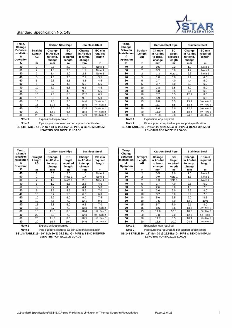
40 2 0.6 2.0 1.0 Note 1 40 2 0.5 2.2 1.0 Note 1 60 2 1.0 2.0 1.7 Note 1 60 2 0.9 3.0 1.7 Note 1 80 2 1.4 2.0 2.3 Note 1 80 2 1.3 Note 1 2.3 Note 1 40 5 1.8 3.0 2.9 3.5 40 5 1.8 3.0 2.9 4.0 60 5 2.8 3.5 4.5 4.5 60 5 2.7 4.0 4.4 5.0 80 5 3.7 4.5 6.0 5.5 80 5 3.7 5.0 5.9 6.0 40 10 3.9 3.5 6.1 4.5 40 10 3.8 3.5 6.0 5.0 60 10 5.9 4.5 9.2 5.5 60 10 5.8 5.5 9.1 6.5 80 10 7.8 5.5 12.2 6.5 80 10 7.7 6.5 12.2 8.0 40 15 6.0 4.0 9.3 5.0 40 15 5.9 4.5 9.3 6.0 60 15 9.0 5.0 14.0 7.0 - Note 2 60 15 8.8 5.5 13.9 7.0 - Note 2 80 15 11.8 6.0 18.6 8.0 - Note 2 80 15 11.7 6.5 18.5 9.0 - Note 2
40 20 8.0 5.5 12.5 7.0 - Note 2 40 20 8.0 5.0 12.4 7.0 - Note 2 60 20 12.2 6.5 18.8 8.0 - Note 2 60 20 11.9 7.5 18.6 9.0 - Note 2 80 20 15.8 7.5 24.9 9.5 - Note 2 80 20 15.8 9.0 24.8 11.0 - Note 2
Note 1 Expansion loop required Note 1 Expansion loop required Note 2 Pipe supports required as per support specification Note 2 Pipe supports required as per support specification
SS 148 TABLE 17 - 6" Sch 40 @ 25.5 Bar G - PIPE & BEND MINIMUM LENGTHS FOR NOZZLE LOADS
SS 148 TABLE 18 - 8" Sch 20 @ 25.5 Bar G - PIPE & BEND MINIMUM LENGTHS FOR NOZZLE LOADS
Temp. Change Between
Installation &
Operation K
Carbon Steel Pipe Stainless Steel Temp. Change Between
Installation &
Operation K
Carbon Steel Pipe Stainless Steel
Straight Length
AB
m
Change in AB due to temp. change
mm
BC target
required length
m
Change in AB due to temp. change
mm
BC min required length
m
Straight Length
AB
m
Change in AB due to temp. change
mm
BC target
required length
m
Change in AB due to temp. change
mm
BC min required length
m
40 2 0.5 2.6 1.0 Note 1 40 2 0.5 3.0 1.0 Note 1 60 2 0.9 Note 1 1.7 Note 1 60 2 0.9 Note 1 1.6 Note 1 80 2 1.3 Note 1 2.3 Note 1 80 2 1.3 Note 1 2.3 Note 1 40 5 1.7 3.5 2.8 4.5 40 5 1.7 4.0 2.8 6.0 60 5 2.7 4.5 4.4 5.8 60 5 2.6 5.0 4.3 7.0 80 5 3.6 5.5 5.9 7.0 80 5 3.6 6.0 5.9 8.0 40 10 3.7 5.0 6.0 6.0 40 10 3.7 5.0 5.9 7.0 60 10 5.7 6.0 9.0 7.5 60 10 5.6 6.5 9.0 8.5 80 10 7.6 7.0 12.1 9.0 80 10 7.5 8.0 12.0 10.0 40 15 5.8 6.0 9.2 7.0 40 15 5.7 7.0 9.1 8.0 60 15 8.7 7.3 13.8 8.5 - Note 2 60 15 8.6 8.5 13.7 10.0 - Note 2
80 15 11.6 8.5 18.4 10.0 - Note 2 80 15 11.6 10.0 18.3 12.0 - Note 2
40 20 7.9 7.0 12.3 8.5 - Note 2 40 20 7.8 7.0 12.3 9.0 - Note 2
60 20 11.8 8.5 18.5 10.5 - Note 2 60 20 11.7 8.5 18.4 11.5 - Note 2
80 20 15.7 10.0 24.6 12.5 - Note 2 80 20 15.6 10.0 24.5 14.0 - Note 2
Note 1 Expansion loop required Note 1 Expansion loop required Note 2 Pipe supports required as per support specification Note 2 Pipe supports required as per support specification
SS 148 TABLE 19 - 10" Sch 20 @ 25.5 Bar G - PIPE & BEND MINIMUM LENGTHS FOR NOZZLE LOADS
SS 148 TABLE 20 - 12" Sch 20 @ 25.5 Bar G - PIPE & BEND MINIMUM LENGTHS FOR NOZZLE LOADS
Standard Specification No. 148
L:\Standard Specifications\SS148.C.Piping Flexibility & Limitation of Thermal Stress in Pipework.doc Page 12 of 28
Temp. Change Between
Installation &
Operation K
Carbon Steel Pipe Stainless Steel Temp. Change Between
Installation &
Operation K
Carbon Steel Pipe Stainless Steel
Straight Length
AB
m
Change in AB due to temp. change
mm
BC target
required length
m
Change in AB due to temp. change
mm
BC min required length
m
Straight Length
AB
m
Change in AB due to temp. change
mm
BC target
required length
m
Change in AB due to temp. change
mm
BC min required length
m
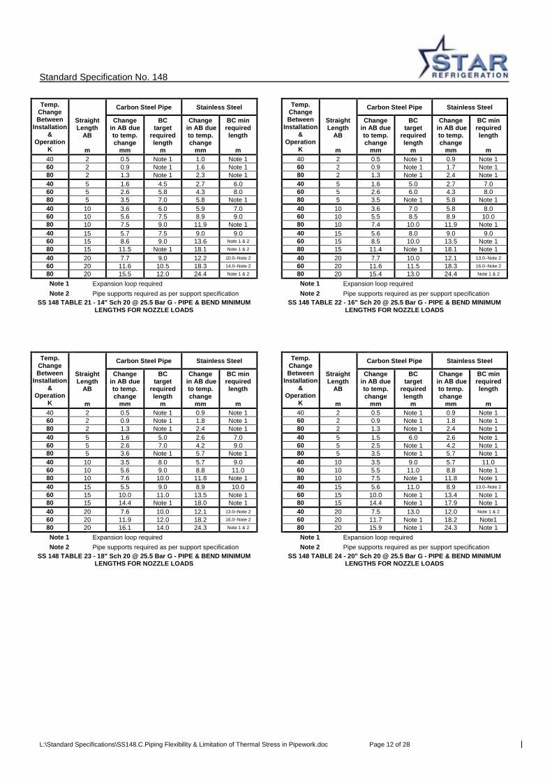
40 2 0.5 Note 1 1.0 Note 1 40 2 0.5 Note 1 0.9 Note 1 60 2 0.9 Note 1 1.6 Note 1 60 2 0.9 Note 1 1.7 Note 1 80 2 1.3 Note 1 2.3 Note 1 80 2 1.3 Note 1 2.4 Note 1 40 5 1.6 4.5 2.7 6.0 40 5 1.6 5.0 2.7 7.0 60 5 2.6 5.8 4.3 8.0 60 5 2.6 6.0 4.3 8.0 80 5 3.5 7.0 5.8 Note 1 80 5 3.5 Note 1 5.8 Note 1 40 10 3.6 6.0 5.9 7.0 40 10 3.6 7.0 5.8 8.0 60 10 5.6 7.5 8.9 9.0 60 10 5.5 8.5 8.9 10.0 80 10 7.5 9.0 11.9 Note 1 80 10 7.4 10.0 11.9 Note 1 40 15 5.7 7.5 9.0 9.0 40 15 5.6 8.0 9.0 9.0 60 15 8.6 9.0 13.6 Note 1 & 2 60 15 8.5 10.0 13.5 Note 1 80 15 11.5 Note 1 18.1 Note 1 & 2 80 15 11.4 Note 1 18.1 Note 1 40 20 7.7 9.0 12.2 10.0–Note 2 40 20 7.7 10.0 12.1 13.0–Note 2
60 20 11.6 10.5 18.3 14.0–Note 2 60 20 11.6 11.5 18.3 16.0–Note 2
80 20 15.5 12.0 24.4 Note 1 & 2 80 20 15.4 13.0 24.4 Note 1 & 2
Note 1 Expansion loop required Note 1 Expansion loop required Note 2 Pipe supports required as per support specification Note 2 Pipe supports required as per support specification
SS 148 TABLE 21 - 14" Sch 20 @ 25.5 Bar G - PIPE & BEND MINIMUM LENGTHS FOR NOZZLE LOADS
SS 148 TABLE 22 - 16" Sch 20 @ 25.5 Bar G - PIPE & BEND MINIMUM LENGTHS FOR NOZZLE LOADS
Temp. Change Between
Installation &
Operation K
Carbon Steel Pipe Stainless Steel Temp. Change Between
Installation &
Operation K
Carbon Steel Pipe Stainless Steel
Straight Length
AB
m
Change in AB due to temp. change
mm
BC target
required length
m
Change in AB due to temp. change
mm
BC min required length
m
Straight Length
AB
m
Change in AB due to temp. change
mm
BC target
required length
m
Change in AB due to temp. change
mm
BC min required length
m
40 2 0.5 Note 1 0.9 Note 1 40 2 0.5 Note 1 0.9 Note 1 60 2 0.9 Note 1 1.8 Note 1 60 2 0.9 Note 1 1.8 Note 1 80 2 1.3 Note 1 2.4 Note 1 80 2 1.3 Note 1 2.4 Note 1 40 5 1.6 5.0 2.6 7.0 40 5 1.5 6.0 2.6 Note 1 60 5 2.6 7.0 4.2 9.0 60 5 2.5 Note 1 4.2 Note 1 80 5 3.6 Note 1 5.7 Note 1 80 5 3.5 Note 1 5.7 Note 1 40 10 3.5 8.0 5.7 9.0 40 10 3.5 9.0 5.7 11.0 60 10 5.6 9.0 8.8 11.0 60 10 5.5 11.0 8.8 Note 1 80 10 7.6 10.0 11.8 Note 1 80 10 7.5 Note 1 11.8 Note 1 40 15 5.5 9.0 8.9 10.0 40 15 5.6 11.0 8.9 13.0–Note 2
60 15 10.0 11.0 13.5 Note 1 60 15 10.0 Note 1 13.4 Note 1 80 15 14.4 Note 1 18.0 Note 1 80 15 14.4 Note 1 17.9 Note 1 40 20 7.6 10.0 12.1 13.0–Note 2 40 20 7.5 13.0 12.0 Note 1 & 2
60 20 11.9 12.0 18.2 16.0–Note 2 60 20 11.7 Note 1 18.2 Note1 80 20 16.1 14.0 24.3 Note 1 & 2 80 20 15.9 Note 1 24.3 Note 1 Note 1 Expansion loop required Note 1 Expansion loop required Note 2 Pipe supports required as per support specification Note 2 Pipe supports required as per support specification
SS 148 TABLE 23 - 18" Sch 20 @ 25.5 Bar G - PIPE & BEND MINIMUM LENGTHS FOR NOZZLE LOADS
SS 148 TABLE 24 - 20" Sch 20 @ 25.5 Bar G - PIPE & BEND MINIMUM LENGTHS FOR NOZZLE LOADS
Standard Specification No. 148
L:\Standard Specifications\SS148.C.Piping Flexibility & Limitation of Thermal Stress in Pipework.doc Page 13 of 28
Temp. Change Between
Installation &
Operation K
Carbon Steel Pipe Stainless Steel Temp. Change Between
Installation &
Operation K
Carbon Steel Pipe Stainless Steel
Straight Length
AB
m
Change in AB due to temp. change
mm
BC min. required length
m
Change in AB due to temp. change
mm
BC min required length
m
Straight Length
AB
m
Change in AB due to temp. change
mm
BC min. required length
m
Change in AB due to temp. change
mm
BC min required length
m
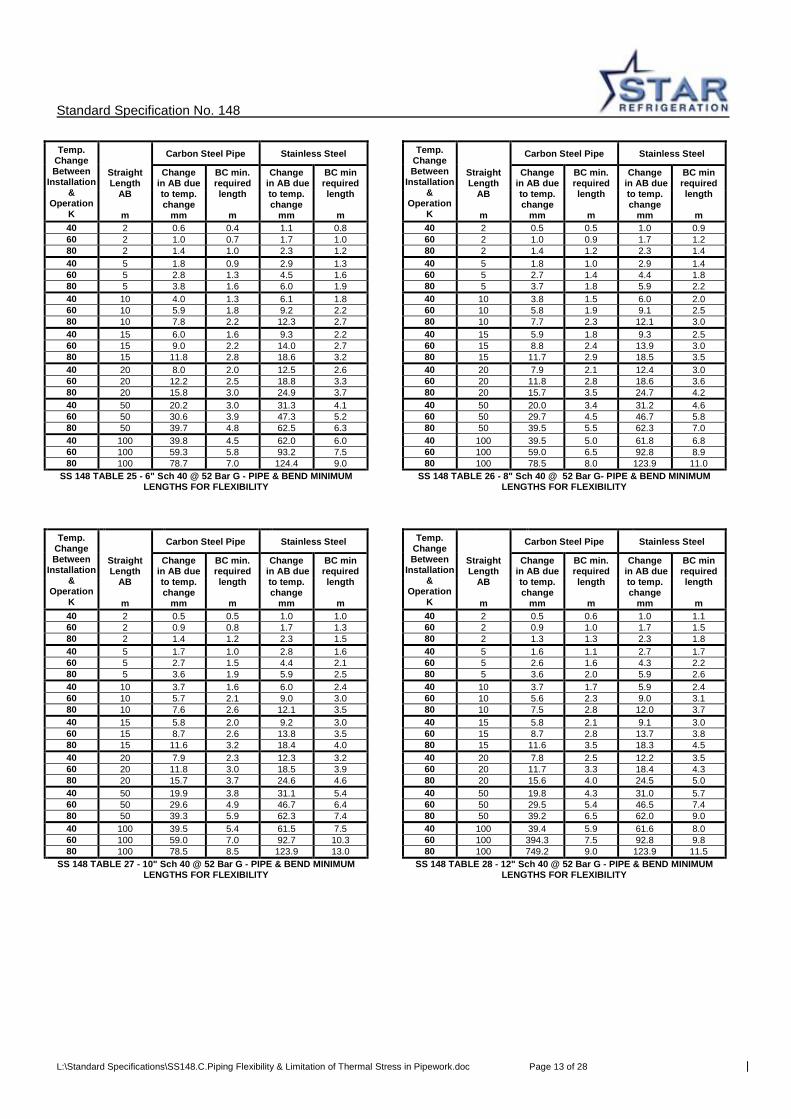
40 2 0.6 0.4 1.1 0.8 40 2 0.5 0.5 1.0 0.9 60 2 1.0 0.7 1.7 1.0 60 2 1.0 0.9 1.7 1.2 80 2 1.4 1.0 2.3 1.2 80 2 1.4 1.2 2.3 1.4 40 5 1.8 0.9 2.9 1.3 40 5 1.8 1.0 2.9 1.4 60 5 2.8 1.3 4.5 1.6 60 5 2.7 1.4 4.4 1.8 80 5 3.8 1.6 6.0 1.9 80 5 3.7 1.8 5.9 2.2 40 10 4.0 1.3 6.1 1.8 40 10 3.8 1.5 6.0 2.0 60 10 5.9 1.8 9.2 2.2 60 10 5.8 1.9 9.1 2.5 80 10 7.8 2.2 12.3 2.7 80 10 7.7 2.3 12.1 3.0 40 15 6.0 1.6 9.3 2.2 40 15 5.9 1.8 9.3 2.5 60 15 9.0 2.2 14.0 2.7 60 15 8.8 2.4 13.9 3.0 80 15 11.8 2.8 18.6 3.2 80 15 11.7 2.9 18.5 3.5 40 20 8.0 2.0 12.5 2.6 40 20 7.9 2.1 12.4 3.0 60 20 12.2 2.5 18.8 3.3 60 20 11.8 2.8 18.6 3.6 80 20 15.8 3.0 24.9 3.7 80 20 15.7 3.5 24.7 4.2 40 50 20.2 3.0 31.3 4.1 40 50 20.0 3.4 31.2 4.6 60 50 30.6 3.9 47.3 5.2 60 50 29.7 4.5 46.7 5.8 80 50 39.7 4.8 62.5 6.3 80 50 39.5 5.5 62.3 7.0 40 100 39.8 4.5 62.0 6.0 40 100 39.5 5.0 61.8 6.8 60 100 59.3 5.8 93.2 7.5 60 100 59.0 6.5 92.8 8.9 80 100 78.7 7.0 124.4 9.0 80 100 78.5 8.0 123.9 11.0
SS 148 TABLE 25 - 6" Sch 40 @ 52 Bar G - PIPE & BEND MINIMUM LENGTHS FOR FLEXIBILITY
SS 148 TABLE 26 - 8" Sch 40 @ 52 Bar G- PIPE & BEND MINIMUM LENGTHS FOR FLEXIBILITY
Temp. Change Between
Installation &
Operation K
Carbon Steel Pipe Stainless Steel Temp. Change Between
Installation &
Operation K
Carbon Steel Pipe Stainless Steel
Straight Length
AB
m
Change in AB due to temp. change
mm
BC min. required length
m
Change in AB due to temp. change
mm
BC min required length
m
Straight Length
AB
m
Change in AB due to temp. change
mm
BC min. required length
m
Change in AB due to temp. change
mm
BC min required length
m
40 2 0.5 0.5 1.0 1.0 40 2 0.5 0.6 1.0 1.1 60 2 0.9 0.8 1.7 1.3 60 2 0.9 1.0 1.7 1.5 80 2 1.4 1.2 2.3 1.5 80 2 1.3 1.3 2.3 1.8 40 5 1.7 1.0 2.8 1.6 40 5 1.6 1.1 2.7 1.7 60 5 2.7 1.5 4.4 2.1 60 5 2.6 1.6 4.3 2.2 80 5 3.6 1.9 5.9 2.5 80 5 3.6 2.0 5.9 2.6 40 10 3.7 1.6 6.0 2.4 40 10 3.7 1.7 5.9 2.4 60 10 5.7 2.1 9.0 3.0 60 10 5.6 2.3 9.0 3.1 80 10 7.6 2.6 12.1 3.5 80 10 7.5 2.8 12.0 3.7 40 15 5.8 2.0 9.2 3.0 40 15 5.8 2.1 9.1 3.0 60 15 8.7 2.6 13.8 3.5 60 15 8.7 2.8 13.7 3.8 80 15 11.6 3.2 18.4 4.0 80 15 11.6 3.5 18.3 4.5 40 20 7.9 2.3 12.3 3.2 40 20 7.8 2.5 12.2 3.5 60 20 11.8 3.0 18.5 3.9 60 20 11.7 3.3 18.4 4.3 80 20 15.7 3.7 24.6 4.6 80 20 15.6 4.0 24.5 5.0 40 50 19.9 3.8 31.1 5.4 40 50 19.8 4.3 31.0 5.7 60 50 29.6 4.9 46.7 6.4 60 50 29.5 5.4 46.5 7.4 80 50 39.3 5.9 62.3 7.4 80 50 39.2 6.5 62.0 9.0 40 100 39.5 5.4 61.5 7.5 40 100 39.4 5.9 61.6 8.0 60 100 59.0 7.0 92.7 10.3 60 100 394.3 7.5 92.8 9.8 80 100 78.5 8.5 123.9 13.0 80 100 749.2 9.0 123.9 11.5
SS 148 TABLE 27 - 10" Sch 40 @ 52 Bar G - PIPE & BEND MINIMUM LENGTHS FOR FLEXIBILITY
SS 148 TABLE 28 - 12" Sch 40 @ 52 Bar G - PIPE & BEND MINIMUM LENGTHS FOR FLEXIBILITY

Standard Specification No. 148
L:\Standard Specifications\SS148.C.Piping Flexibility & Limitation of Thermal Stress in Pipework.doc Page 14 of 28
Temp. Change Between
Installation &
Operation K
Carbon Steel Pipe Stainless Steel Temp. Change Between
Installation &
Operation K
Carbon Steel Pipe Stainless Steel
Straight Length
AB
m
Change in AB due to temp. change
mm
BC min. required length
m
Change in AB due to temp. change
mm
BC min required length
m
Straight Length
AB
m
Change in AB due to temp. change
mm
BC min. required length
m
Change in AB due to temp. change
mm
BC min required length
m
40 2 0.6 0.6 1.0 1.3 40 2 0.6 0.8 1.2 2.0 60 2 1.0 0.9 1.7 1.9 60 2 1.0 1.3 More Flexibility Req. 80 2 1.5 1.4 2.5 2.5 80 2 1.5 1.8 More Flexibility Req. 40 5 1.8 1.3 2.9 1.7 40 5 1.8 1.9 2.9 2.8 60 5 2.8 1.6 4.5 2.1 60 5 2.8 2.4 4.5 3.4 80 5 3.9 2.0 6.2 2.5 80 5 3.9 3.0 6.2 4.0 40 10 3.9 1.6 6.1 2.9 40 10 3.9 2.9 6.1 3.7 60 10 5.9 2.1 9.2 3.5 60 10 5.9 3.7 9.2 4.6 80 10 7.3 2.5 12.5 4.0 80 10 8.0 4.5 12.6 5.5 40 15 6.0 2.0 9.3 3.4 40 15 6.0 3.0 9.3 4.1 60 15 9.0 2.6 14.0 4.2 60 15 9.0 3.9 14.0 5.0 80 15 11.9 3.2 18.8 5.0 80 15 12.0 4.8 18.9 5.8 40 20 8.0 2.4 12.5 4.2 40 20 8.0 3.3 12.5 5.4 60 20 12.2 3.2 18.8 5.4 60 20 12.2 4.4 18.8 6.4 80 20 15.9 4.0 25.2 6.0 80 20 16.0 5.5 25.2 7.5 40 50 20.3 5.0 31.5 7.2 40 50 20.3 6.2 31.5 8.5 60 50 30.6 6.5 47.3 9.1 60 50 30.6 8.1 47.3 10.8 80 50 39.9 8.0 62.9 11.0 80 50 37.0 10.0 62.8 13.0 40 100 40.8 7.1 63.0 9.9 40 100 40.8 8.1 63.0 12.9 60 100 57.6 9.0 93.9 11.9 60 100 59.8 10.6 93.9 15.4 80 100 74.4 11.0 124.7 14.0 80 100 78.9 13.0 124.7 18.0
SS 148 TABLE 29 - 6" Sch40 @ 52 Bar G - PIPE, BEND & TEE MIN. LENGTHS FOR FLEXIBILITY
SS 148 TABLE 30 - 8" Sch 40 @ 52 Bar G - PIPE, BEND & TEE MIN. LENGTHS FOR FLEXIBILITY
Temp. Change Between
Installation &
Operation K
Carbon Steel Pipe Stainless Steel Temp. Change Between
Installation &
Operation K
Carbon Steel Pipe Stainless Steel
Straight Length
AB
m
Change in AB due to temp. change
mm
BC min. required length
m
Change in AB due to temp. change
mm
BC min required length
m
Straight Length
AB
m
Change in AB due to temp. change
mm
BC min. required length
m
Change in AB due to temp. change
mm
BC min required length
m
40 2 0.8 2.0 More Flexibility Req. 40 2 0.7 2.0 More Flexibility Req. 60 2 More Flexibility Req. More Flexibility Req. 60 2 More Flexibility Req. More Flexibility Req. 80 2 More Flexibility Req. More Flexibility Req. 80 2 More Flexibility Req. More Flexibility Req. 40 5 1.8 1.7 2.9 3.5 40 5 1.8 2.1 2.9 3.7 60 5 2.8 2.5 4.5 4.5 60 5 2.8 2.9 4.5 4.7 80 5 3.9 3.3 6.3 5.5 80 5 3.9 3.8 6.3 5.7 40 10 3.9 3.1 6.1 4.1 40 10 3.9 3.0 6.1 5.2 60 10 5.9 4.0 9.2 5.3 60 10 5.9 4.0 9.2 6.6 80 10 8.0 5.0 12.6 6.5 80 10 8.0 5.0 12.6 8.0 40 15 6.0 3.8 9.3 4.7 40 15 6.0 4.2 9.3 5.3 60 15 9.0 4.9 14.0 5.9 60 15 9.0 5.6 14.0 6.7 80 15 12.0 6.0 18.9 7.0 80 15 12.0 7.0 18.9 8.0 40 20 8.0 4.4 12.5 6.6 40 20 8.0 5.0 12.5 7.7 60 20 12.2 5.7 18.8 8.1 60 20 12.2 6.5 18.8 9.4 80 20 16.0 7.0 25.2 9.5 80 20 16.0 8.0 25.2 11.0 40 50 20.3 7.1 31.5 11.7 40 50 20.3 8.6 31.5 12.8 60 50 30.6 9.0 47.3 13.8 60 50 30.6 10.8 47.3 15.4 80 50 39.8 11.0 62.8 16.0 80 50 39.9 13.0 62.8 18.0 40 100 40.8 11.4 63.0 15.8 40 100 40.8 12.5 63.0 17.4 60 100 59.9 14.7 93.8 19.4 60 100 59.8 15.7 94.3 21.2 80 100 79.0 18.0 124.6 23.0 80 100 78.8 19.0 124.6 25.0
SS 148 TABLE 31- 10" Sch 40 @ 52 Bar G - PIPE, BEND & TEE MIN. LENGTHS FOR FLEXIBILITY
SS 148 TABLE 32 - 12" Sch 40 @ 52 Bar G - PIPE, BEND & TEE MIN. LENGTHS FOR FLEXIBILITY

Standard Specification No. 148
L:\Standard Specifications\SS148.C.Piping Flexibility & Limitation of Thermal Stress in Pipework.doc Page 15 of 28
Temp. Change Between
Installation &
Operation K
Carbon Steel Pipe Stainless Steel Temp. Change Between
Installation &
Operation K
Carbon Steel Pipe Stainless Steel
Straight Length
AB
m
Change in AB due to temp. change
mm
BC target
required length
m
Change in AB due to temp. change
mm
BC min required length
m
Straight Length
AB
m
Change in AB due to temp. change
mm
BC target
required length
m
Change in AB due to temp. change
mm
BC min required length
m
40 2 0.6 2.0 1.0 Note 1 40 2 0.8 2.2 1.0 Note 1 60 2 1.0 2.0 1.7 Note 1 60 2 1.3 3.0 1.7 Note 1 80 2 1.4 Note 1 2.3 Note 1 80 2 1.5 Note 1 2.3 Note 1 40 5 1.8 3.0 2.9 3.5 40 5 2.0 3.5 3.1 4.0 60 5 2.8 3.5 4.5 4.5 60 5 3.0 4.0 4.7 5.5 80 5 3.9 4.5 6.0 5.5 80 5 4.0 5.0 5.9 Note 1 40 10 3.9 3.5 6.3 4.5 40 10 4.1 3.5 6.3 5.0 60 10 6.1 4.5 9.4 5.5 60 10 6.1 Note 1 9.2 Note 1 80 10 7.9 5.5 12.5 6.5 80 10 7.7 Note 1 12.2 Note 1 40 15 6.0 4.0 9.3 5.0 – Note 2 40 15 5.9 Note 1 9.3 Note 1 60 15 9.0 5.0 14.2 7.0 – Note 2 60 15 8.8 Note 1 13.9 Note 1 80 15 11.9 6.0 18.8 8.0 – Note 2 80 15 11.7 Note 1 18.5 Note 1 40 20 8.3 5.5 12.7 7.0 – Note 2 40 20 8.0 Note 1 12.4 Note 1 60 20 12.3 6.5 19.0 8.0 – Note 2 60 20 11.9 Note 1 18.6 Note 1 80 20 16.0 7.5 24.9 Note 1 & 2 80 20 15.8 Note 1 24.8 Note 1 Note 1 Expansion loop required Note 1 Expansion loop required Note 2 Pipe supports required as per support specification
SS 148 TABLE 33 - 6" Sch 40 @ 52 Bar G - PIPE & BEND MINIMUM LENGTHS FOR NOZZLE LOADS
SS 148 TABLE 34 - 8" Sch 40 @ 52 Bar G - PIPE & BEND MINIMUM LENGTHS FOR NOZZLE LOADS
Temp. Change Between
Installation &
Operation K
Carbon Steel Pipe Stainless Steel Temp. Change Between
Installation &
Operation K
Carbon Steel Pipe Stainless Steel
Straight Length
AB
m
Change in AB due to temp. change
mm
BC target
required length
m
Change in AB due to temp. change
mm
BC min required length
m
Straight Length
AB
m
Change in AB due to temp. change
mm
BC target
required length
m
Change in AB due to temp. change
mm
BC min required length
m
40 2 0.5 Note 1 1.0 Note 1 40 2 0.5 Note 1 1.0 Note 1 60 2 0.9 Note 1 1.7 Note 1 60 2 0.9 Note 1 1.6 Note 1 80 2 1.3 Note 1 2.3 Note 1 80 2 1.3 Note 1 2.3 Note 1 40 5 2.0 4.5 2.8 4.5 40 5 2.0 4.0 3.2 6.0 60 5 2.8 Note 1 4.4 Note 1 60 5 3.1 6.0 4.9 Note 1 80 5 3.6 Note 1 5.9 Note 1 80 5 4.1 Note 1 6.4 Note 1 40 10 4.1 6.0 6.0 8.0 – Note 2 40 10 4.1 6.0 6.3 7.0 – Note 2
60 10 5.9 6.5 9.3 9.0 – Note 2 60 10 6.0 7.5 9.4 8.5 – Note 2
80 10 7.6 7.0 12.6 10.0–Note 2 80 10 8.0 9.0 12.5 10.0–Note 2
40 15 6.2 7.0 9.2 Note 1 & 2 40 15 6.2 7.0 9.5 9.0 – Note 2
60 15 9.1 8.5 13.8 Note 1 & 2 60 15 9.1 9.0 14.3 11.5–Note 2
80 15 12.0 10.0 18.4 Note 1 & 2 80 15 12.0 11.0 19.1 14.0–Note 2
40 20 8.3 8.0 12.3 Note 1 & 2 40 20 8.3 9.0 12.7 12.0–Note 2
60 20 12.2 10.0 18.5 Note 1 & 2 60 20 12.2 11.0 19.0 15.0–Note 2
80 20 16.0 12.0 24.6 Note 1 & 2 80 20 16.0 13.0 25.3 18.0–Note 2
Note 1 Expansion loop required Note 1 Expansion loop required Note 2 Springs required local to nozzle Note 2 Springs required local to nozzle
SS 148 TABLE 35 - 10" Sch 40 @ 54 Bar G - PIPE & BEND MINIMUM LENGTHS FOR NOZZLE LOADS
SS 148 TABLE 36 - 12" Sch 40 @ 52Bar G - PIPE & BEND MINIMUM LENGTHS FOR NOZZLE LOADS
Standard Specification No. 148
L:\Standard Specifications\SS148.C.Piping Flexibility & Limitation of Thermal Stress in Pipework.doc Page 16 of 28
Temp. Change Between
Installation &
Operation K
Carbon Steel Pipe Stainless Steel Temp. Change Between
Installation &
Operation K
Carbon Steel Pipe Stainless Steel
Straight Length
AB
m
Change in AB due to temp. change
mm
BC min. required length
m
Change in AB due to temp. change
mm
BC min required length
m
Straight Length
AB
m
Change in AB due to temp. change
mm
BC min. required length
m
Change in AB due to temp. change
mm
BC min required length
m
60 K 2 1.2 0.5 1.8 0.6 60 K 2 1.2 0.5 1.8 0.7 80 K 2 1.6 0.6 2.4 0.7 80 K 2 1.6 0.6 2.4 0.8
100 K 2 2.0 0.6 3.0 0.8 100 K 2 2.0 0.7 3.0 0.9 120 K 2 2.5 0.7 3.6 0.9 120 K 2 2.5 0.8 3.6 1.0 60 K 5 3.0 0.7 4.7 1.0 60 K 5 3.0 0.8 4.6 1.2 80 K 5 4.1 0.9 6.2 1.2 80 K 5 4.0 1.0 6.1 1.4
100 K 5 5.2 1.0 7.6 1.3 100 K 5 4.9 1.1 7.6 1.6 120 K 5 6.4 1.1 9.1 1.5 120 K 5 6.3 1.3 9.0 1.7 60 K 10 6.1 1.0 9.5 1.4 60 K 10 6.1 1.2 9.4 1.7 80 K 10 8.4 1.2 12.5 1.7 80 K 10 8.3 1.5 12.4 2.0
100 K 10 10.6 1.4 15.5 2.0 100 K 10 10.5 1.7 15.4 2.3 120 K 10 12.9 1.6 18.3 2.2 120 K 10 12.8 1.9 18.3 2.5 60 K 15 9.2 1.3 14.2 1.9 60 K 15 9.2 1.5 14.2 2.2 80 K 15 12.6 1.6 18.7 2.3 80 K 15 12.6 1.9 18.7 2.7
100 K 15 15.9 1.9 23.2 2.7 100 K 15 15.9 2.2 23.2 3.1 120 K 15 19.4 2.2 27.6 3.0 120 K 15 19.3 2.5 26.7 3.5 60 K 20 12.3 1.5 19.0 2.2 60 K 20 12.3 1.8 19.0 2.6 80 K 20 16.8 1.9 25.1 2.6 80 K 20 16.8 2.2 25.0 3.1
100 K 20 21.3 2.2 31.1 3.0 100 K 20 21.2 2.5 31.0 3.5 120 K 20 25.9 2.4 36.9 3.3 120 K 20 25.9 2.9 36.8 3.9 60 K 50 30.8 2.7 45.5 3.8 60 K 50 30.7 3.1 47.4 4.3 80 K 50 42.0 3.3 60.6 4.5 80 K 50 41.9 3.8 62.5 5.2
100 K 50 53.2 3.8 75.7 5.2 100 K 50 53.1 4.4 77.6 6.0 120 K 50 64.8 4.3 92.3 5.7 120 K 50 64.8 4.9 92.2 6.6 60 K 100 60.9 4.1 94.3 5.8 60 K 100 60.8 4.7 94.2 6.7 80 K 100 83.4 4.9 124.6 6.8 80 K 100 83.2 5.7 124.5 7.9
100 K 100 105.8 5.7 154.9 7.8 100 K 100 105.6 6.6 154.7 9.0 120 K 100 129.1 6.4 180.3 8.6 120 K 100 129.0 7.4 183.8 9.9 60 K 200 118.8 6.1 185.4 8.6 60 K 200 118.3 7.0 184.9 9.9 80 K 200 163.7 7.3 246.0 10.1 80 K 200 163.1 8.4 245.4 11.6
100 K 200 208.5 8.5 306.5 11.5 100 K 200 207.9 9.8 305.9 13.2 120 K 200 255.2 9.6 364.8 12.7 120 K 200 254.6 11.0 364.2 14.6 60 K 300 173.4 7.6 273.0 10.7 60 K 300 172.1 8.7 271.8 12.3 80 K 300 240.7 9.1 363.9 12.6 80 K 300 239.4 10.5 362.6 14.4
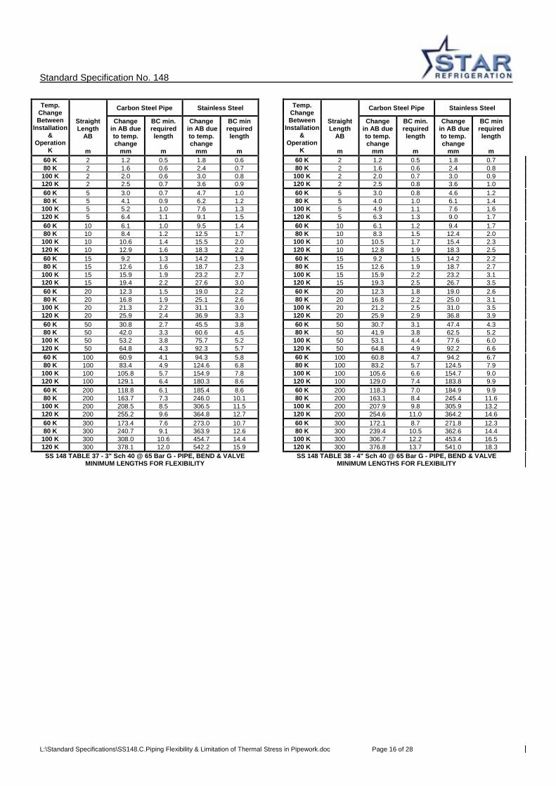
100 K 300 308.0 10.6 454.7 14.4 100 K 300 306.7 12.2 453.4 16.5 120 K 300 378.1 12.0 542.2 15.9 120 K 300 376.8 13.7 541.0 18.3 SS 148 TABLE 37 - 3" Sch 40 @ 65 Bar G - PIPE, BEND & VALVE
MINIMUM LENGTHS FOR FLEXIBILITY SS 148 TABLE 38 - 4" Sch 40 @ 65 Bar G - PIPE, BEND & VALVE
MINIMUM LENGTHS FOR FLEXIBILITY

Standard Specification No. 148
L:\Standard Specifications\SS148.C.Piping Flexibility & Limitation of Thermal Stress in Pipework.doc Page 17 of 28
Temp. Change Between
Installation &
Operation K
Carbon Steel Pipe Stainless Steel Temp. Change Between
Installation &
Operation K
Carbon Steel Pipe Stainless Steel
Straight Length
AB
m
Change in AB due to temp. change
mm
BC min. required length
m
Change in AB due to temp. change
mm
BC min required length
m
Straight Length
AB
m
Change in AB due to temp. change
mm
BC min. required length
m
Change in AB due to temp. change
mm
BC min required length
m
40 K 2 0.7 0.5 1.2 0.7 40 K 2 0.7 0.6 1.2 0.8 60 K 2 1.2 0.6 1.8 0.9 60 K 2 1.1 0.8 1.8 1.1 80 K 2 1.6 0.7 2.4 1.0 80 K 2 1.5 0.9 2.4 1.3
100 K 2 2.1 0.9 2.9 1.2 100 K 2 2.3 1.1 3.0 1.5 120 K 2 2.5 1.0 3.4 1.4 120 K 2 2.5 1.2 More Flexibility Req. 40 K 5 1.9 0.8 3.0 1.1 40 K 5 1.9 0.9 3.0 1.3 60 K 5 3.0 1.0 4.6 1.4 60 K 5 2.9 1.2 4.5 1.7 80 K 5 4.0 1.2 6.1 1.7 80 K 5 3.9 1.4 6.0 2.0
100 K 5 5.1 1.4 7.6 2.0 100 K 5 5.1 1.7 7.5 2.3 120 K 5 6.2 1.6 9.0 2.2 120 K 5 6.2 1.9 8.9 2.6 40 K 10 4.0 1.1 6.2 1.6 40 K 10 4.0 1.4 6.1 1.9 60 K 10 6.1 1.5 9.3 2.1 60 K 10 6.1 1.8 9.2 2.5 80 K 10 8.2 1.8 12.3 2.5 80 K 10 8.1 2.1 12.2 3.0
100 K 10 10.5 2.1 15.2 2.9 100 K 10 10.4 2.5 15.1 3.4 120 K 10 12.7 2.4 18.1 3.2 120 K 10 12.6 2.8 18.0 3.8 40 K 15 6.1 1.5 9.4 2.1 40 K 15 6.0 1.8 9.4 2.4 60 K 15 9.3 1.9 14.1 2.7 60 K 15 9.2 2.3 14.0 3.1 80 K 15 12.4 2.3 18.7 3.2 80 K 15 12.3 2.7 18.6 3.7
100 K 15 15.9 2.7 23.1 3.6 100 K 15 15.7 3.1 22.9 4.2 120 K 15 19.3 3.0 27.4 4.0 120 K 15 19.1 3.5 27.2 4.6 40 K 20 8.2 1.8 12.6 2.5 40 K 20 8.1 2.1 12.5 2.9 60 K 20 12.4 2.3 18.8 3.2 60 K 20 12.3 2.7 18.7 3.7 80 K 20 16.6 2.7 25.0 3.8 80 K 20 16.5 3.2 24.8 4.5
100 K 20 21.2 3.2 30.8 4.3 100 K 20 21.1 3.7 30.6 5.1 120 K 20 25.7 3.6 36.6 4.8 120 K 20 25.6 4.2 36.4 5.6 40 K 50 20.4 3.1 31.5 4.4 40 K 50 20.2 3.5 31.4 5.0 60 K 50 31.0 3.9 47.1 5.5 60 K 50 30.8 4.5 46.9 6.3 80 K 50 41.6 4.7 62.6 6.6 80 K 50 41.4 5.4 62.4 7.6
100 K 50 53.1 5.5 77.3 7.5 100 K 50 52.9 6.3 77.1 8.6 120 K 50 64.6 6.2 92.0 8.3 120 K 50 64.4 7.1 91.8 9.6 40 K 100 40.0 4.6 62.3 6.5 40 K 100 39.8 5.3 62.0 7.1 60 K 100 61.3 5.9 93.4 8.2 60 K 100 61.1 6.8 93.1 9.2 80 K 100 82.5 7.1 124.5 9.8 80 K 100 82.3 8.2 124.2 11.3
100 K 100 105.6 8.2 159.3 11.3 100 K 100 105.3 9.4 153.7 12.8 120 K 100 128.6 9.2 194.0 12.7 120 K 100 128.3 10.6 183.1 14.3 40 K 200 76.4 6.7 120.6 9.6 40 K 200 75.8 7.8 119.9 11.0 60 K 200 117.1 8.6 183.8 12.2 60 K 200 118.4 9.9 182.2 13.8 80 K 200 161.3 10.4 245.2 14.5 80 K 200 161.0 12.0 244.5 16.6
100 K 200 212.9 12.2 316.6 16.7 100 K 200 207.0 13.8 303.5 19.3 120 K 200 253.6 13.5 378.0 19.1 120 K 200 253.0 15.6 362.4 22.0 40 K 300 109.3 8.0 175.3 11.4 40 K 300 119.6 9.9 174.0 13.1 60 K 300 170.5 10.3 270.2 14.6 60 K 300 169.4 11.9 268.9 16.7 80 K 300 236.8 12.4 362.3 17.3 80 K 300 241.2 14.3 364.2 19.8
100 K 300 314.1 14.6 469.5 20.0 100 K 300 313.1 16.6 459.4 22.8 120 K 300 375.2 16.1 561.6 22.1 120 K 300 384.9 19.0 554.7 25.9 SS 148 TABLE 39 - 6" Sch 40 @ 65 Bar G - PIPE, BEND & VALVE
MINIMUM LENGTHS FOR FLEXIBILITY SS 148 TABLE 40 - 8" Sch 40 @ 65 Bar G - PIPE, BEND & VALVE
MINIMUM LENGTHS FOR FLEXIBILITY

Standard Specification No. 148
L:\Standard Specifications\SS148.C.Piping Flexibility & Limitation of Thermal Stress in Pipework.doc Page 18 of 28
Temp. Change Between
Installation &
Operation K
Carbon Steel Pipe Stainless Steel Temp. Change Between
Installation &
Operation K
Carbon Steel Pipe Stainless Steel
Straight Length
AB
m
Change in AB due to temp. change
mm
BC min. required length
m
Change in AB due to temp. change
mm
BC min required length
m
Straight Length
AB
m
Change in AB due to temp. change
mm
BC min. required length
m
Change in AB due to temp. change
mm
BC min required length
m
40 K 2 0.7 0.7 1.1 0.9 60 K 2 1.3 1.0 2.0 1.4 60 K 2 1.1 0.8 1.8 1.2 80 K 2 1.7 1.2 2.5 1.6 80 K 2 1.5 1.0 2.4 1.5 100 K 2 2.1 1.3 3.1 1.7
100 K 2 2.0 1.2 More Flexibility Req. 120 K 2 2.6 1.5 3.7 1.9 120 K 2 2.5 1.4 More Flexibility Req. 60 K 5 3.1 1.3 4.8 1.8 40 K 5 1.8 1.0 2.9 1.5 80 K 5 4.2 1.5 6.2 2.0 60 K 5 2.9 1.3 4.5 1.9 100 K 5 5.3 1.7 7.7 2.3 80 K 5 3.9 1.6 6.0 2.3 120 K 5 6.5 1.9 9.2 2.5
100 K 5 5.1 1.9 7.5 2.7 60 K 10 6.2 1.7 9.6 2.3 120 K 5 6.2 2.2 8.9 3.0 80 K 10 8.4 2.0 12.5 2.7 40 K 10 3.9 1.5 6.1 2.2 100 K 10 10.7 2.2 15.5 3.0 60 K 10 6.0 2.0 9.2 2.8 120 K 10 13.0 2.5 18.5 3.4 80 K 10 8.0 2.4 12.2 3.4 60 K 15 9.3 2.0 14.3 2.9
100 K 10 10.3 2.8 15.1 3.9 80 K 15 12.7 2.4 18.8 3.4 120 K 10 12.5 3.2 18.0 4.3 100 K 15 16.1 2.8 23.3 3.9 40 K 15 6.0 1.9 9.3 2.8 120 K 15 19.5 3.2 27.8 4.4 60 K 15 9.1 2.5 13.9 3.5 60 K 20 12.4 2.4 19.1 3.4 80 K 15 12.2 3.0 18.4 4.2 80 K 20 16.9 2.9 25.1 4.0
100 K 15 15.6 3.5 22.8 4.8 100 K 20 21.5 3.3 31.1 4.5 120 K 15 19.0 3.9 27.1 5.3 120 K 20 26.1 3.8 37.1 5.1 40 K 20 8.0 2.3 12.4 3.3 60 K 50 30.8 4.1 47.7 6.0 60 K 20 12.2 3.0 18.6 4.2 80 K 50 42.2 4.9 62.6 7.0 80 K 20 16.4 3.6 24.7 5.0 100 K 50 53.6 5.6 77.6 8.1
100 K 20 21.0 4.2 30.6 5.7 120 K 50 65.0 6.4 92.6 9.1 120 K 20 25.5 4.7 36.4 6.4 60 K 100 61.0 6.2 94.5 8.8 40 K 50 20.2 4.1 31.3 5.6 80 K 100 83.7 7.3 124.4 10.2 60 K 50 28.8 5.2 46.8 7.1 100 K 100 106.5 8.4 154.4 11.7 80 K 50 37.3 6.2 62.3 8.6 120 K 100 129.3 9.5 184.3 13.1
100 K 50 50.8 7.2 77.0 9.8 60 K 200 118.9 8.9 185.6 12.8 120 K 50 64.2 8.1 91.6 10.9 80 K 200 164.4 10.4 245.4 14.9 40 K 100 39.6 6.0 61.7 8.5 100 K 200 209.9 12.0 305.3 16.9 60 K 100 60.8 7.6 92.9 10.5 120 K 200 255.4 13.5 365.2 19.0 80 K 100 82.0 9.2 124.0 12.4 60 K 300 173.5 11.0 273.2 15.0
100 K 100 105.0 10.6 153.4 14.3 80 K 300 241.7 12.9 362.9 17.3 120 K 100 128.0 12.0 182.8 16.1 100 K 300 310.0 14.7 452.7 19.5 40 K 200 75.1 8.6 119.2 12.3 120 K 300 378.3 16.6 542.4 21.8 60 K 200 117.7 11.1 181.6 15.5 SS 148 TABLE 42 - 3" Sch 40 @ 65 Bar G - PIPE, BEND & TEE 80 K 200 160.2 13.5 243.9 18.7 MINIMUM LENGTHS FOR FLEXIBILITY
100 K 200 206.3 15.6 303.0 22.2 120 K 200 252.3 17.6 362.1 25.6 40 K 300 107.1 10.3 172.9 14.7 60 K 300 170.9 13.2 266.4 18.5 80 K 300 234.7 16.1 359.9 22.3
100 K 300 303.9 18.6 448.4 25.4 120 K 300 373.0 21.1 536.8 28.5 SS 148 TABLE 41 - 10" Sch 40 @ 65 Bar G - PIPE, BEND & VALVE
MINIMUM LENGTHS FOR FLEXIBILITY

Standard Specification No. 148
L:\Standard Specifications\SS148.C.Piping Flexibility & Limitation of Thermal Stress in Pipework.doc Page 19 of 28
Temp. Change Between
Installation &
Operation K
Carbon Steel Pipe Stainless Steel Temp. Change Between
Installation &
Operation K
Carbon Steel Pipe Stainless Steel
Straight Length
AB
m
Change in AB due to temp. change
mm
BC min. required length
m
Change in AB due to temp. change
mm
BC min required length
m
Straight Length
AB
m
Change in AB due to temp. change
mm
BC min. required length
m
Change in AB due to temp. change
mm
BC min required length
m
60 K 2 1.3 1.2 1.9 1.5 40 K 2 0.8 1.1 1.2 1.5 80 K 2 1.7 1.4 2.5 1.8 60 K 2 1.2 1.4 1.9 2.2
100 K 2 2.1 1.5 3.1 2.2 80 K 2 1.7 1.6 More Flexibility Req. 120 K 2 2.6 1.7 More Flexibility Req. 100 K 2 2.1 2.1 More Flexibility Req. 60 K 5 3.1 1.5 4.8 2.0 120 K 2 More Flexibility Req. More Flexibility Req. 80 K 5 4.2 1.7 6.3 2.4 40 K 5 2.0 1.4 3.1 2.0
100 K 5 5.3 2.0 7.8 2.8 60 K 5 3.1 1.8 4.8 2.7 120 K 5 6.5 2.2 9.3 3.2 80 K 5 4.2 2.2 6.4 3.4 60 K 10 6.1 1.9 9.5 2.7 100 K 5 5.3 2.7 7.9 4.0 80 K 10 8.4 2.3 12.5 3.2 120 K 5 6.5 3.1 9.3 4.5
100 K 10 10.7 2.7 15.5 3.7 40 K 10 4.0 1.9 6.3 2.9 120 K 10 13.0 3.1 18.5 4.2 60 K 10 6.2 2.6 9.6 3.8 60 K 15 9.2 2.4 14.3 3.6 80 K 10 8.4 3.2 12.8 4.6 80 K 15 12.6 2.9 18.8 4.2 100 K 10 10.7 3.7 15.7 5.2
100 K 15 16.1 3.5 23.3 4.8 120 K 10 13.0 4.2 18.5 5.8 120 K 15 19.6 4.0 27.8 5.4 40 K 15 6.1 2.5 9.5 3.8 60 K 20 12.4 2.9 19.1 4.1 60 K 15 9.3 3.3 14.2 4.8 80 K 20 16.9 3.5 25.0 4.8 80 K 15 12.6 4.1 18.9 5.8
100 K 20 21.5 4.0 31.0 5.5 100 K 15 16.0 4.8 23.4 6.6 120 K 20 26.1 4.6 37.0 6.2 120 K 15 19.5 5.4 27.8 7.4 60 K 50 30.8 5.0 47.6 7.4 40 K 20 8.2 3.1 12.7 4.5 80 K 50 42.2 5.9 62.6 8.7 60 K 20 12.5 4.0 19.0 5.7
100 K 50 53.6 6.9 77.6 9.9 80 K 20 16.9 4.8 25.3 6.8 120 K 50 65.0 7.8 92.6 11.2 100 K 20 21.5 5.5 31.2 7.7 60 K 100 60.9 7.5 94.4 10.7 120 K 20 26.1 6.2 37.1 8.5 80 K 100 83.6 8.8 124.3 12.6 40 K 50 20.5 5.3 31.7 7.9
100 K 100 106.4 10.0 154.3 14.4 60 K 50 31.2 6.7 47.3 10.1 120 K 100 129.2 11.3 184.3 16.3 80 K 50 41.8 8.1 62.9 12.2 60 K 200 118.4 10.8 185.2 15.6 100 K 50 53.3 9.3 77.7 14.2 80 K 200 163.9 12.6 245.1 18.2 120 K 50 64.9 10.4 92.4 16.2
100 K 200 209.4 14.4 305.1 20.9 40 K 100 40.2 7.8 62.5 11.4 120 K 200 255.0 16.2 365.0 23.5 60 K 100 61.5 9.8 93.7 14.5 60 K 300 172.5 13.3 272.0 18.0 80 K 100 82.8 11.8 124.9 17.6 80 K 300 240.7 15.5 361.7 20.7 100 K 100 105.9 13.4 154.4 18.8
100 K 300 308.9 17.7 451.5 23.5 120 K 100 129.0 15.0 183.9 19.9 120 K 300 377.2 19.9 541.2 26.2 40 K 200 76.8 11.1 120.9 15.4
SS 148 TABLE 43 - 4" Sch 40 @ 65 Bar G - PIPE, BEND & TEE 60 K 200 119.4 14.0 183.3 19.0 MINIMUM LENGTHS FOR FLEXIBILITY 80 K 200 161.9 16.9 245.7 22.6
100 K 200 208.1 19.3 304.8 25.4 120 K 200 254.2 21.7 363.8 28.1 40 K 300 109.5 13.7 175.3 18.7 60 K 300 173.3 17.2 268.9 23.2 80 K 300 237.1 20.6 362.5 27.7 100 K 300 306.3 23.5 451.0 31.1 120 K 300 375.5 26.3 539.5 34.5
SS 148 TABLE 44 - 6" Sch 40 @ 65 Bar G - PIPE, BEND & TEE
MINIMUM LENGTHS FOR FLEXIBILITY
Standard Specification No. 148
L:\Standard Specifications\SS148.C.Piping Flexibility & Limitation of Thermal Stress in Pipework.doc Page 20 of 28
Temp. Change Between
Installation &
Operation K
Carbon Steel Pipe Stainless Steel Temp. Change Between
Installation &
Operation K
Carbon Steel Pipe Stainless Steel
Straight Length
AB
m
Change in AB due to temp. change
mm
BC min. required length
m
Change in AB due to temp. change
mm
BC min required length
m
Straight Length
AB
m
Change in AB due to temp. change
mm
BC min. required length
m
Change in AB due to temp. change
mm
BC min required length
m
40 K 2 0.8 1.2 1.2 1.9 40 K 2 0.7 1.3 More Flexibility Req. 60 K 2 1.3 1.8 More Flexibility Req. 60 K 2 1.2 2.1 More Flexibility Req. 80 K 2 1.7 2.3 More Flexibility Req. 80 K 2 More Flexibility Req. More Flexibility Req. 100 K 2 More Flexibility Req. More Flexibility Req. 100 K 2 More Flexibility Req. More Flexibility Req. 120 K 2 More Flexibility Req. More Flexibility Req. 120 K 2 More Flexibility Req. More Flexibility Req. 40 K 5 1.9 1.6 3.1 2.5 40 K 5 1.9 1.8 3.1 3.0 60 K 5 3.0 2.2 4.8 3.5 60 K 5 3.1 2.7 4.8 4.3 80 K 5 4.1 2.8 6.4 4.4 80 K 5 4.2 3.5 6.4 5.6 100 K 5 5.3 3.4 7.8 5.1 100 K 5 5.4 4.3 More Flexibility Req. 120 K 5 6.5 4.0 More Flexibility Req. 120 K 5 6.5 5.0 More Flexibility Req. 40 K 10 4.0 2.3 6.3 3.6 40 K 10 4.0 2.8 6.3 4.2 60 K 10 6.2 3.1 9.5 4.6 60 K 10 6.2 3.8 9.5 5.5 80 K 10 8.4 3.9 12.6 5.6 80 K 10 8.4 4.7 12.6 6.7 100 K 10 10.7 4.6 15.6 6.4 100 K 10 10.7 5.5 15.6 7.7 120 K 10 13.0 5.2 18.5 7.1 120 K 10 13.0 6.3 18.5 8.6 40 K 15 6.1 3.2 9.5 4.6 40 K 15 6.1 3.8 9.5 5.5 60 K 15 9.4 4.2 14.2 5.9 60 K 15 9.4 5.0 14.2 7.0 80 K 15 12.6 5.1 18.9 7.1 80 K 15 12.6 6.1 18.9 8.5 100 K 15 16.1 5.9 23.4 8.2 100 K 15 16.1 7.1 23.4 9.9 120 K 15 19.5 6.7 27.8 9.2 120 K 15 19.5 8.0 27.8 11.3 40 K 20 8.2 3.7 12.7 5.4 40 K 20 8.2 4.5 12.7 6.3 60 K 20 12.5 4.8 19.0 6.8 60 K 20 12.5 5.7 19.0 8.1 80 K 20 16.8 5.9 25.2 8.1 80 K 20 16.8 6.9 25.3 9.8 100 K 20 21.4 6.8 31.2 9.2 100 K 20 21.4 8.0 31.2 11.1 120 K 20 26.0 7.7 37.1 10.2 120 K 20 26.0 9.1 37.1 12.3 40 K 50 20.5 6.5 31.7 9.7 40 K 50 20.4 7.5 31.7 11.5 60 K 50 31.2 8.2 47.3 12.6 60 K 50 31.1 9.6 47.3 15.4 80 K 50 41.8 9.9 62.9 15.5 80 K 50 41.8 11.6 62.9 19.3 100 K 50 53.4 11.4 77.7 19.5 100 K 50 53.4 13.3 More Flexibility Req. 120 K 50 64.9 12.9 92.5 23.5 120 K 50 64.9 14.9 More Flexibility Req. 40 K 100 40.1 9.5 62.4 14.1 40 K 100 40.0 11.1 62.3 16.8 60 K 100 61.4 11.8 93.6 18.3 60 K 100 61.3 13.8 93.6 23.5 80 K 100 82.7 14.1 124.8 22.5 80 K 100 82.6 16.5 124.8 30.2 100 K 100 105.8 16.2 154.3 23.5 100 K 100 105.7 19.0 More Flexibility Req. 120 K 100 128.9 18.2 183.8 24.4 120 K 100 128.8 21.5 More Flexibility Req. 40 K 200 64.6 13.5 120.5 18.7 40 K 200 75.9 15.6 120.0 21.8 60 K 200 113.0 16.8 182.9 23.1 60 K 200 118.5 19.6 183.3 27.1 80 K 200 161.4 20.1 245.2 27.5 80 K 200 161.0 23.5 More Flexibility Req. 100 K 200 207.6 23.0 304.9 30.9 100 K 200 207.2 26.9 More Flexibility Req. 120 K 200 253.7 25.8 More Flexibility Req. 120 K 200 253.3 30.2 More Flexibility Req. 40 K 300 108.4 16.1 174.2 22.6 40 K 300 107.5 18.9 173.2 26.0 60 K 300 172.2 20.5 267.8 28.2 60 K 300 171.3 23.9 268.1 33.0 80 K 300 236.0 24.8 361.3 33.7 80 K 300 235.1 28.8 More Flexibility Req. 100 K 300 305.2 28.4 More Flexibility Req. 100 K 300 303.3 32.7 More Flexibility Req. 120 K 300 374.4 32.0 More Flexibility Req. 120 K 300 More Flexibility Req. More Flexibility Req.
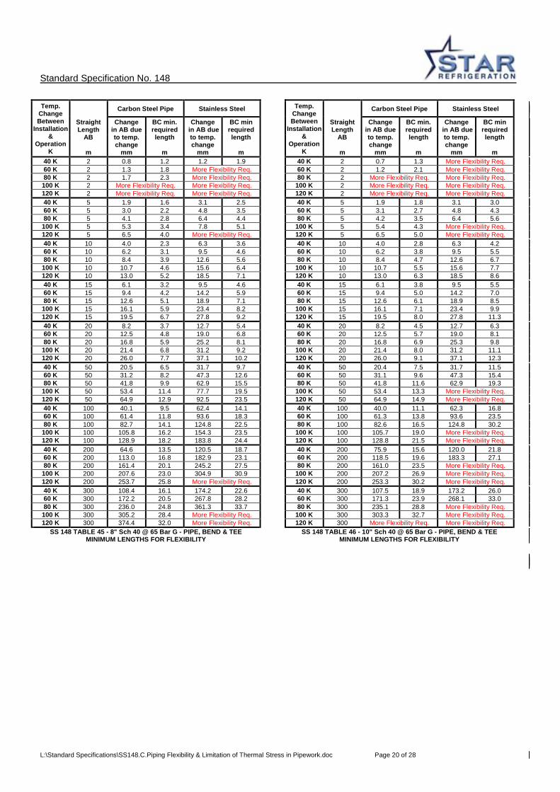
SS 148 TABLE 45 - 8" Sch 40 @ 65 Bar G - PIPE, BEND & TEE MINIMUM LENGTHS FOR FLEXIBILITY
SS 148 TABLE 46 - 10" Sch 40 @ 65 Bar G - PIPE, BEND & TEE MINIMUM LENGTHS FOR FLEXIBILITY
Standard Specification No. 148
L:\Standard Specifications\SS148.C.Piping Flexibility & Limitation of Thermal Stress in Pipework.doc Page 21 of 28
Temp. Change Between
Installation &
Operation K
Carbon Steel Pipe Stainless Steel Temp. Change Between
Installation &
Operation K
Carbon Steel Pipe Stainless Steel
Straight Length
AB
m
Change in AB due to temp. change
mm
BC min. required length
m
Change in AB due to temp. change
mm
BC min required length
m
Straight Length
AB
m
Change in AB due to temp. change
mm
BC min. required length
m
Change in AB due to temp. change
mm
BC min required length
m
60K 2 1.2 1.2 1.9 1.7 60K 2 1.2 1.4 1.9 1.9 80K 2 1.6 1.6 2.5 2.0 80K 2 1.6 1.8 2.5 2.6
100 K 2 1.9 1.9 3.1 2.6 100 K 2 1.9 1.9 3.2 3.0 120 K 2 2.3 2.1 3.7 2.9 120 K 2 2.3 2.3 3.8 3.8 60K 5 3.1 2.0 4.7 2.3 60K 5 3.1 2.1 4.7 2.6 80K 5 4.0 2.3 6.3 2.7 80K 5 4.0 2.6 6.2 3.0
100 K 5 4.9 2.6 7.7 3.1 100 K 5 4.9 3.0 7.7 3.5 120 K 5 5.8 2.9 9.2 3.4 120 K 5 5.9 3.4 9.2 3.9 60K 10 6.1 2.0 9.4 2.6 60K 10 6.1 2.6 9.5 3.0 80K 10 8.0 2.4 12.5 3.0 80K 10 8.0 3.0 12.5 3.6
100 K 10 9.7 2.7 15.5 3.4 100 K 10 9.7 3.4 15.5 4.1 120 K 10 11.5 3.0 18.4 3.8 120 K 10 11.5 3.8 18.4 4.5 60K 15 9.3 3.4 - Note 2 14.3 4.7 - Note 2 60K 15 9.3 4.3 - Note 2 14.3 5.1 - Note 2 80K 15 12.1 4.0 - Note 2 19.0 5.4 - Note 2 80K 15 12.1 4.7 - Note 2 19.0 5.8 - Note 2
100 K 15 14.7 4.7 - Note 2 23.4 6.2 - Note 2 100 K 15 14.7 5.1 - Note 2 23.5 6.8 - Note 2 120 K 15 17.5 5.2 - Note 2 27.9 7.2 - Note 2 120 K 15 17.5 5.7 - Note 2 27.9 7.7 - Note 2
60K 20 12.4 4.3 -Note 2 19.1 5.6 - Note 2 60K 20 12.4 4.7 - Note 2 19.1 5.7 - Note 2 80K 20 16.1 5.0 - Note 2 25.3 6.3 - Note 2 80K 20 16.1 5.3 - Note 2 25.3 6.9 - Note 2
100 K 20 19.6 5.7 - Note 2 31.3 7.4 - Note 2 100 K 20 19.6 6.0 - Note 2 31.3 8.0 - Note 2 120 K 20 23.3 6.3 - Note 2 37.1 8.4 - Note 2 120 K 20 23.3 6.8 - Note 2 37.2 9.2 - Note 2
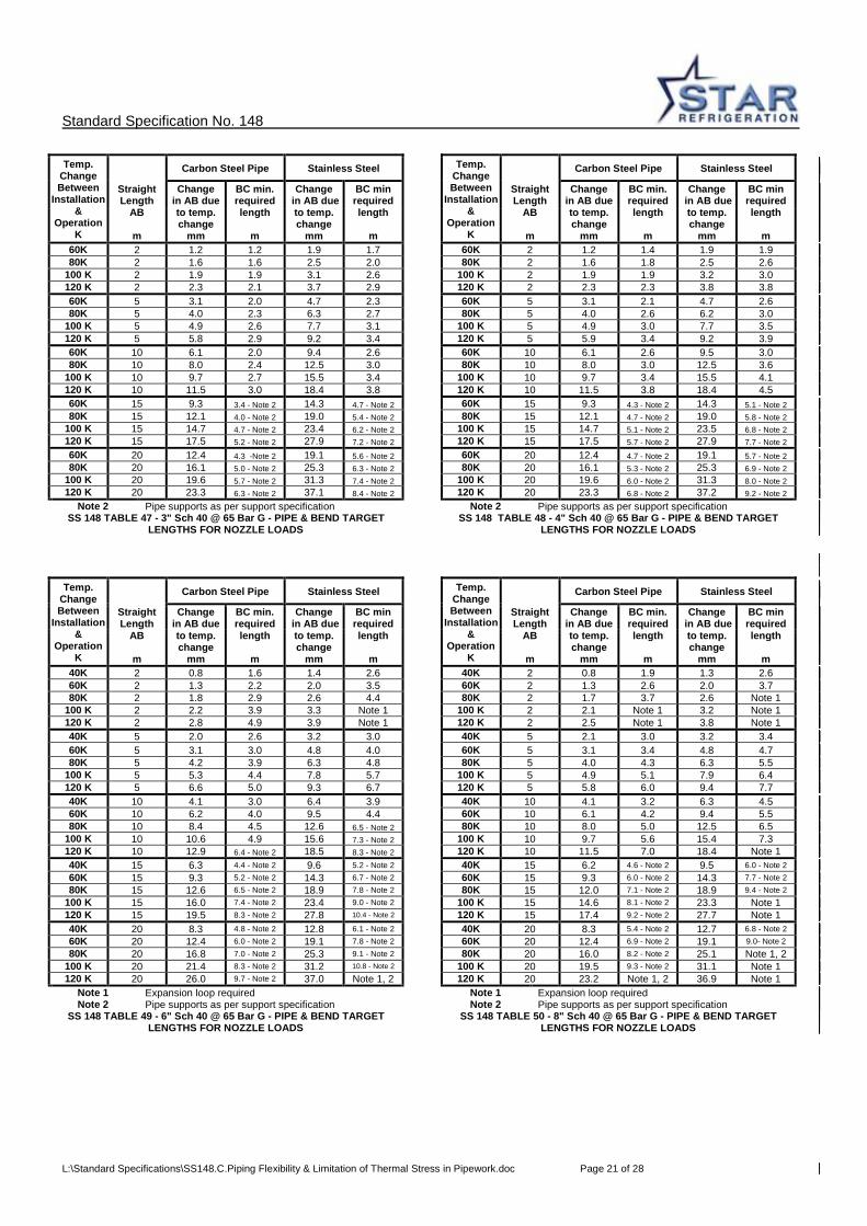
Note 2 Pipe supports as per support specification Note 2 Pipe supports as per support specification SS 148 TABLE 47 - 3" Sch 40 @ 65 Bar G - PIPE & BEND TARGET
LENGTHS FOR NOZZLE LOADS SS 148 TABLE 48 - 4" Sch 40 @ 65 Bar G - PIPE & BEND TARGET
LENGTHS FOR NOZZLE LOADS
Temp. Change Between
Installation &
Operation K
Carbon Steel Pipe Stainless Steel Temp. Change Between
Installation &
Operation K
Carbon Steel Pipe Stainless Steel
Straight Length
AB
m
Change in AB due to temp. change
mm
BC min. required length
m
Change in AB due to temp. change
mm
BC min required length
m
Straight Length
AB
m
Change in AB due to temp. change
mm
BC min. required length
m
Change in AB due to temp. change
mm
BC min required length
m
40K 2 0.8 1.6 1.4 2.6 40K 2 0.8 1.9 1.3 2.6 60K 2 1.3 2.2 2.0 3.5 60K 2 1.3 2.6 2.0 3.7 80K 2 1.8 2.9 2.6 4.4 80K 2 1.7 3.7 2.6 Note 1
100 K 2 2.2 3.9 3.3 Note 1 100 K 2 2.1 Note 1 3.2 Note 1 120 K 2 2.8 4.9 3.9 Note 1 120 K 2 2.5 Note 1 3.8 Note 1 40K 5 2.0 2.6 3.2 3.0 40K 5 2.1 3.0 3.2 3.4 60K 5 3.1 3.0 4.8 4.0 60K 5 3.1 3.4 4.8 4.7 80K 5 4.2 3.9 6.3 4.8 80K 5 4.0 4.3 6.3 5.5
100 K 5 5.3 4.4 7.8 5.7 100 K 5 4.9 5.1 7.9 6.4 120 K 5 6.6 5.0 9.3 6.7 120 K 5 5.8 6.0 9.4 7.7 40K 10 4.1 3.0 6.4 3.9 40K 10 4.1 3.2 6.3 4.5 60K 10 6.2 4.0 9.5 4.4 60K 10 6.1 4.2 9.4 5.5 80K 10 8.4 4.5 12.6 6.5 - Note 2 80K 10 8.0 5.0 12.5 6.5
100 K 10 10.6 4.9 15.6 7.3 - Note 2 100 K 10 9.7 5.6 15.4 7.3 120 K 10 12.9 6.4 - Note 2 18.5 8.3 - Note 2 120 K 10 11.5 7.0 18.4 Note 1 40K 15 6.3 4.4 - Note 2 9.6 5.2 - Note 2 40K 15 6.2 4.6 - Note 2 9.5 6.0 - Note 2 60K 15 9.3 5.2 - Note 2 14.3 6.7 - Note 2 60K 15 9.3 6.0 - Note 2 14.3 7.7 - Note 2 80K 15 12.6 6.5 - Note 2 18.9 7.8 - Note 2 80K 15 12.0 7.1 - Note 2 18.9 9.4 - Note 2
100 K 15 16.0 7.4 - Note 2 23.4 9.0 - Note 2 100 K 15 14.6 8.1 - Note 2 23.3 Note 1 120 K 15 19.5 8.3 - Note 2 27.8 10.4 - Note 2 120 K 15 17.4 9.2 - Note 2 27.7 Note 1 40K 20 8.3 4.8 - Note 2 12.8 6.1 - Note 2 40K 20 8.3 5.4 - Note 2 12.7 6.8 - Note 2 60K 20 12.4 6.0 - Note 2 19.1 7.8 - Note 2 60K 20 12.4 6.9 - Note 2 19.1 9.0- Note 2 80K 20 16.8 7.0 - Note 2 25.3 9.1 - Note 2 80K 20 16.0 8.2 - Note 2 25.1 Note 1, 2
100 K 20 21.4 8.3 - Note 2 31.2 10.8 - Note 2 100 K 20 19.5 9.3 - Note 2 31.1 Note 1 120 K 20 26.0 9.7 - Note 2 37.0 Note 1, 2 120 K 20 23.2 Note 1, 2 36.9 Note 1
Note 1 Expansion loop required Note 1 Expansion loop required Note 2 Pipe supports as per support specification Note 2 Pipe supports as per support specification
SS 148 TABLE 49 - 6" Sch 40 @ 65 Bar G - PIPE & BEND TARGET LENGTHS FOR NOZZLE LOADS
SS 148 TABLE 50 - 8" Sch 40 @ 65 Bar G - PIPE & BEND TARGET LENGTHS FOR NOZZLE LOADS
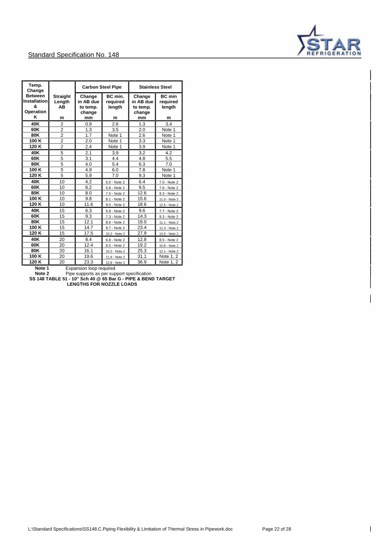
Standard Specification No. 148
L:\Standard Specifications\SS148.C.Piping Flexibility & Limitation of Thermal Stress in Pipework.doc Page 22 of 28
Temp. Change Between
Installation &
Operation K
Carbon Steel Pipe Stainless Steel
Straight Length
AB
m
Change in AB due to temp. change
mm
BC min. required length
m
Change in AB due to temp. change
mm
BC min required length
m
40K 2 0.9 2.6 1.3 3.4 60K 2 1.3 3.5 2.0 Note 1 80K 2 1.7 Note 1 2.6 Note 1
100 K 2 2.0 Note 1 3.3 Note 1 120 K 2 2.4 Note 1 3.9 Note 1 40K 5 2.1 3.9 3.2 4.2 60K 5 3.1 4.4 4.8 5.5 80K 5 4.0 5.4 6.3 7.0
100 K 5 4.9 6.0 7.8 Note 1 120 K 5 5.9 7.0 9.3 Note 1 40K 10 4.2 5.0 - Note 2 6.4 7.0 - Note 2 60K 10 6.2 5.8 - Note 2 9.5 7.6 - Note 2 80K 10 8.0 7.0 - Note 2 12.6 9.3 - Note 2
100 K 10 9.8 8.1 - Note 2 15.6 11.0 - Note 2 120 K 10 11.6 9.0 - Note 2 18.6 12.5 - Note 2 40K 15 6.3 5.9 - Note 2 9.6 7.7 - Note 2 60K 15 9.3 7.3 - Note 2 14.3 9.3 - Note 2 80K 15 12.1 8.6 - Note 2 19.0 11.1 - Note 2
100 K 15 14.7 9.7 - Note 2 23.4 12.3 - Note 2 120 K 15 17.5 10.2 - Note 2 27.9 14.5 - Note 2 40K 20 8.4 6.8 - Note 2 12.8 8.5 - Note 2 60K 20 12.4 8.5 - Note 2 19.2 10.8 - Note 2 80K 20 16.1 10.2 - Note 2 25.3 12.1 - Note 2
100 K 20 19.6 11.6 - Note 2 31.1 Note 1, 2 120 K 20 23.3 12.8 - Note 2 36.9 Note 1, 2
Note 1 Expansion loop required Note 2 Pipe supports as per support specification
SS 148 TABLE 51 - 10" Sch 40 @ 65 Bar G - PIPE & BEND TARGET LENGTHS FOR NOZZLE LOADS
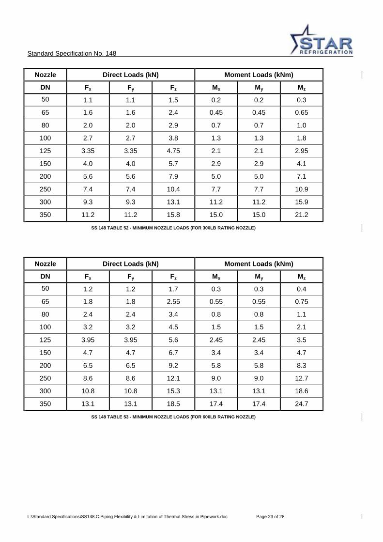
Standard Specification No. 148
L:\Standard Specifications\SS148.C.Piping Flexibility & Limitation of Thermal Stress in Pipework.doc Page 23 of 28
Nozzle Direct Loads (kN) Moment Loads (kNm)
DN Fx Fy Fz Mx My Mz
50
1.1 1.1 1.5 0.2 0.2 0.3
65 1.6 1.6 2.4 0.45 0.45 0.65
80 2.0 2.0 2.9 0.7 0.7 1.0
100 2.7 2.7 3.8 1.3 1.3 1.8
125 3.35 3.35 4.75 2.1 2.1 2.95
150 4.0 4.0 5.7 2.9 2.9 4.1
200 5.6 5.6 7.9 5.0 5.0 7.1
250 7.4 7.4 10.4 7.7 7.7 10.9
300 9.3 9.3 13.1 11.2 11.2 15.9
350 11.2 11.2 15.8 15.0 15.0 21.2
SS 148 TABLE 52 - MINIMUM NOZZLE LOADS (FOR 300LB RATING NOZZLE)
Nozzle Direct Loads (kN) Moment Loads (kNm)
DN Fx Fy Fz Mx My Mz
50
1.2 1.2 1.7 0.3 0.3 0.4
65 1.8 1.8 2.55 0.55 0.55 0.75
80 2.4 2.4 3.4 0.8 0.8 1.1
100 3.2 3.2 4.5 1.5 1.5 2.1
125 3.95 3.95 5.6 2.45 2.45 3.5
150 4.7 4.7 6.7 3.4 3.4 4.7
200 6.5 6.5 9.2 5.8 5.8 8.3
250 8.6 8.6 12.1 9.0 9.0 12.7
300 10.8 10.8 15.3 13.1 13.1 18.6
350 13.1 13.1 18.5 17.4 17.4 24.7
SS 148 TABLE 53 - MINIMUM NOZZLE LOADS (FOR 600LB RATING NOZZLE)
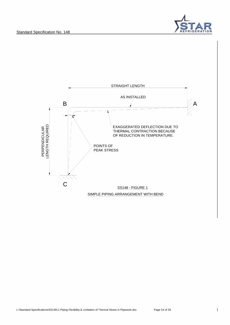
Standard Specification No. 148
L:\Standard Specifications\SS148.C.Piping Flexibility & Limitation of Thermal Stress in Pipework.doc Page 24 of 28
.
PER
PEN
DIC
ULA
RLE
NG
TH R
EQU
IRED
STRAIGHT LENGTH
POINTS OF PEAK STRESS
EXAGGERATED DEFLECTION DUE TO THERMAL CONTRACTION BECAUSE OF REDUCTION IN TEMPERATURE.
AS INSTALLED
B A
CSS148 - FIGURE 1
SIMPLE PIPING ARRANGEMENT WITH BEND
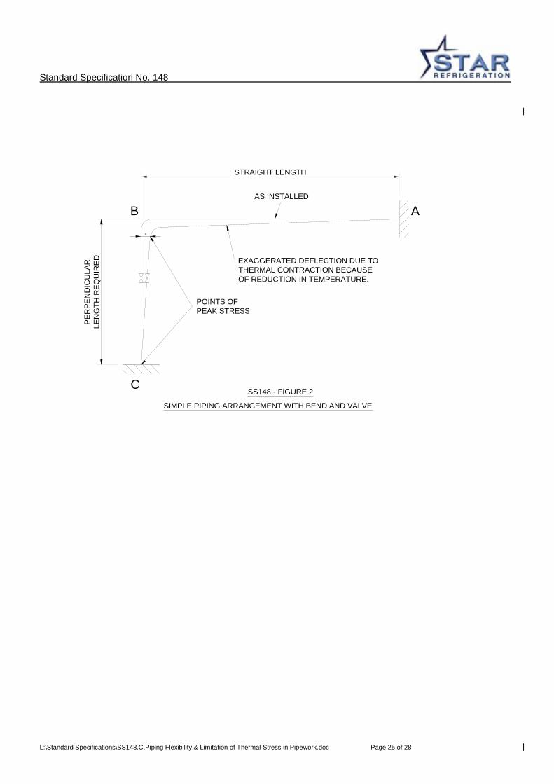
Standard Specification No. 148
L:\Standard Specifications\SS148.C.Piping Flexibility & Limitation of Thermal Stress in Pipework.doc Page 25 of 28
SS148 - FIGURE 2C
ABAS INSTALLED
EXAGGERATED DEFLECTION DUE TO THERMAL CONTRACTION BECAUSE OF REDUCTION IN TEMPERATURE.
POINTS OF PEAK STRESS
STRAIGHT LENGTH
PE
RPE
ND
ICU
LAR
LEN
GTH
RE
QU
IRE
D
.
SIMPLE PIPING ARRANGEMENT WITH BEND AND VALVE
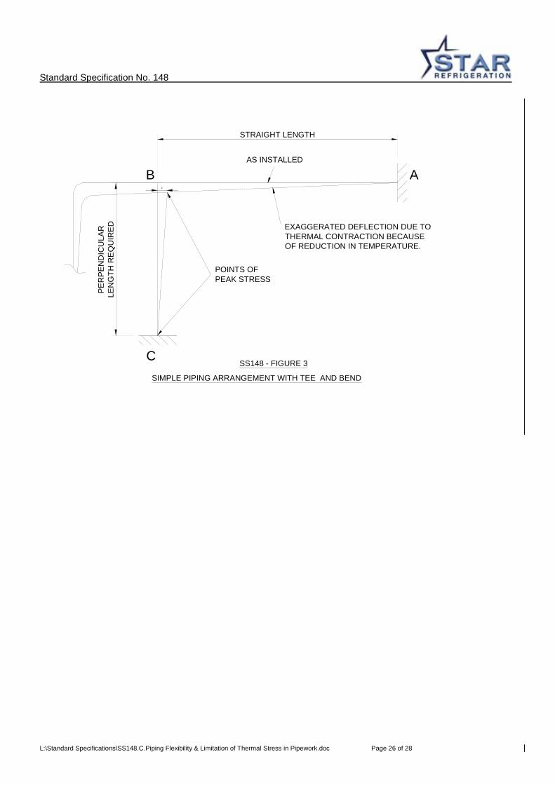
Standard Specification No. 148
L:\Standard Specifications\SS148.C.Piping Flexibility & Limitation of Thermal Stress in Pipework.doc Page 26 of 28
SIMPLE PIPING ARRANGEMENT WITH TEE AND BEND
.
PER
PEN
DIC
ULA
RLE
NG
TH R
EQ
UIR
ED
STRAIGHT LENGTH
POINTS OF PEAK STRESS
EXAGGERATED DEFLECTION DUE TO THERMAL CONTRACTION BECAUSE OF REDUCTION IN TEMPERATURE.
AS INSTALLED
B A
CSS148 - FIGURE 3
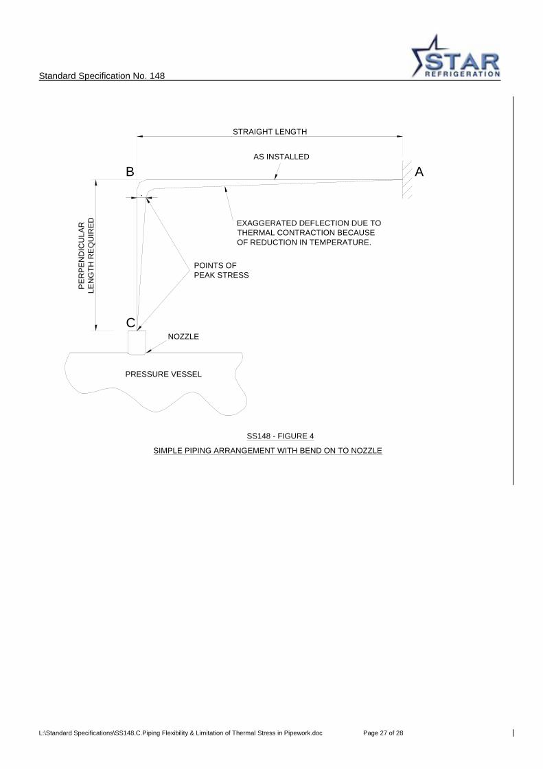
Standard Specification No. 148
L:\Standard Specifications\SS148.C.Piping Flexibility & Limitation of Thermal Stress in Pipework.doc Page 27 of 28
SIMPLE PIPING ARRANGEMENT WITH BEND ON TO NOZZLE
SS148 - FIGURE 4
C
ABAS INSTALLED
EXAGGERATED DEFLECTION DUE TO THERMAL CONTRACTION BECAUSE OF REDUCTION IN TEMPERATURE.
POINTS OF PEAK STRESS
STRAIGHT LENGTH
PE
RP
EN
DIC
ULA
RLE
NG
TH R
EQ
UIR
ED
.
NOZZLE
PRESSURE VESSEL

Standard Specification No. 148
L:\Standard Specifications\SS148.C.Piping Flexibility & Limitation of Thermal Stress in Pipework.doc Page 28 of 28
STRAIGHT LENGTH - AB
AS INSTALLED
B A
C
SS148 - FIGURE 5
WORKED EXAMPLE (SECTION 4.0)
D
STRAIGHT LENGTH - CD
C'
STR
AIG
HT
LEN
GTH
- B
C
STR
AIG
HT
LEN
GTH
-BC
'ST
RA
IGH
T LE
NG
TH -
CC
'