
SS12 THRU SS120 - hdiodecom.s506.000pc.nethdiodecom.s506.000pc.net/down/SS12-SS120(J).pdf · SS 14...
4
SMAJ Plastic-Encapsulate Diodes HD AJ 28-32 Features ●I o 1A ●VRRM ●High surge current capability Applications ● Rectifier ● : From 2 To 20 X Marking Polarity: Color band denotes cathode ● SS1X 1 High Diode Semiconductor SMAJ SS12 THRU SS120 Schottky Rectifier 20V-200V Item Symbol Unit Test Conditions SS 12 SS 13 SS 14 SS 15 SS 16 SS 18 SS 110 SS 115 SS 120 Repetitive Peak Reverse Voltage VRRM V 20 30 40 50 60 80 100 150 200 Average Forward Current IF(AV) A 60HZ Half-sine wave, Resistance load, TL(Fig.1) 1.0 Surge(Non-repetitive)Forward Current IFSM A 60Hz Half-sine wave ,1 cycle , Ta =25 ℃ 30 Junction Temperature TJ ℃ -55~+125 -55~+150 Storage Temperature TSTG ℃ -55 ~ +150 Electrical Characteristics (T a =25℃ Unless otherwise specified ) Item Symbol Unit Test Condition SS 12 SS 13 SS 14 SS 15 SS 16 SS 18 SS 110 SS 115 SS 120 Peak Forward Voltage V F V I F =1.0A 0.55 0.70 0.85 0.95 Peak Reverse Current I RRM1 mA VRM=VRRM T a =25 ℃ 0.5 0.2 I RRM2 T a =100 ℃ 10 5.0 Thermal Resistance(Typical) R θJ-A /W ℃ Between junction and ambient 88 1) R θJ-L Between junction and terminal 28 1) Notes: Thermal resistance from junction to ambient and from junction to lead mounted on P.C.B. with 0.2" x 0.2" (5.0 mm x 5.0 mm) copper pad areas Maximum RMS Vo V RMS V 14 21 28 35 42 56 70 ltage 105 140 Maximum DC blocking Voltage V V DC 20 30 40 50 60 80 100 150 200 Typical junction capactiance Measured at 1.0MHz and applied reverse voltage of 4.0 volts. CJ pF 110 60
Transcript of SS12 THRU SS120 - hdiodecom.s506.000pc.nethdiodecom.s506.000pc.net/down/SS12-SS120(J).pdf · SS 14...
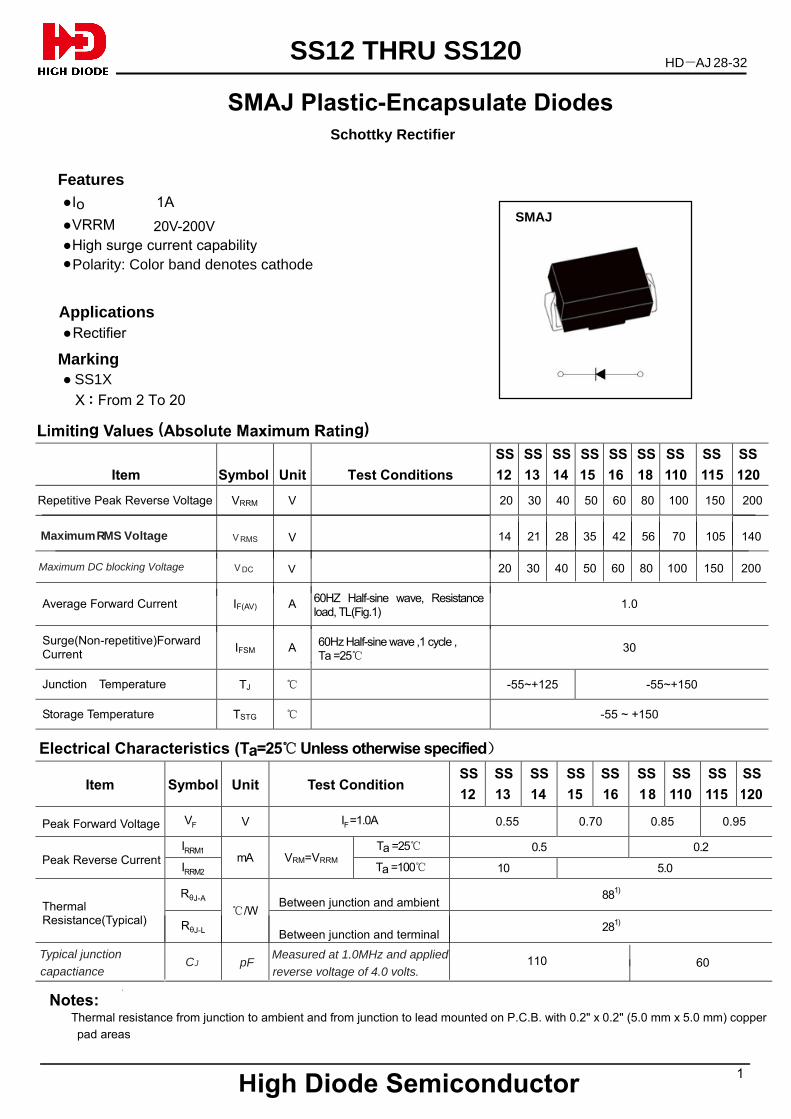
SMAJ Plastic-Encapsulate Diodes
HD AJ 28-32
Features
●Io 1A
●VRRM
●High surge current capability
Applications ● Rectifier
● : From 2 To 20X
Marking
Polarity: Color band denotes cathode●
SS1X
1
H igh Diode Semiconductor
SMAJ
SS12 THRU SS120
Schottky Rectifier
20V-200V
Item
Symbol
Unit
Test Conditions
SS
12
SS
13
SS
14
SS
15
SS
16
SS
18
SS
110
SS
115
SS
120
Repetitive Peak Reverse Voltage VRRM V 20 30 40 50 60 80 100 150 200
Average Forward Current IF(AV) A
60HZ Half-sine wave, Resistance load, TL(Fig.1)
1.0
Surge(Non-repetitive)Forward Current
IFSM A
60Hz Half-sine wave ,1 cycle , Ta =25℃
30
Junction Temperature TJ ℃ -55~+125 -55~+150
Storage Temperature TSTG ℃ -55 ~ +150
Electrical Characteristics (Ta=25℃ Unless otherwise specified)
Item
Symbol
Unit
Test Condition
SS
12
SS
13
SS
14
SS
15
SS
16
SS
18
SS
110
SS
115
SS
120
Peak Forward Voltage VF V IF =1.0A 0.55 0.70 0.85 0.95
Peak Reverse Current
IRRM1 mA VRM=VRRM
Ta =25℃ 0.5 0.2
IRRM2 Ta =100℃ 10 5.0
Thermal Resistance(Typical)
RθJ-A
/W℃
Between junction and ambient
881)
RθJ-L
Between junction and terminal 28
1)
Notes: Thermal resistance from junction to ambient and from junction to lead mounted on P.C.B. with 0.2" x 0.2" (5.0 mm x 5.0 mm) copper
pad areas
Maximum RMS Vo V RMS V 14 21 28 35 42 56 70ltage 105 140
Maximum DC blocking Voltage V V DC 20 30 40 50 60 80 100 150 200
Typical junction capactiance
Measured at 1.0MHz and applied reverse voltage of 4.0 volts.
CJ pF 110 60
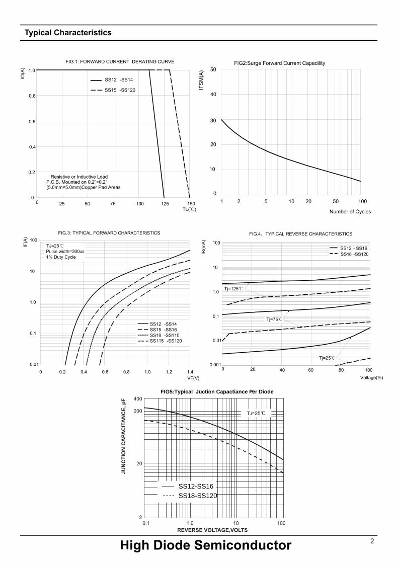
Typical Characteristics
2 H igh Diode Semiconductor
0 50 150
FIG.1: FORWARD CURRENT DERATING CURVE
IO(A
)
Resistive or Inductive LoadP.C.B. Mounted on 0.2"×0.2"(5.0mm×5.0mm)Copper Pad Areas
TL(℃)100
0.2
0.4
0.6
0.8
1.0
0
25 75 125
SS12 -SS14
SS15 -SS120
IF(A
)
FIG.3: TYPICAL FORWARD CHARACTERISTICS
0.01
VF(V)
0.4
TJ=25℃Pulse width=300us1% Duty Cycle
0.1
1.0
10
100
0.6 0.8 1.0 1.2 1.4
SS12 -SS14SS15 -SS16SS18 -SS110SS115 -SS120
0.20
FIG.4:TYPICAL REVERSE CHARACTERISTICS
Voltage(%)
IR(m
A)
0 20 40 60 80 1000.001
Tj=25℃
Tj=75℃
100
10
1.0
0.1
0.01
Tj=125℃
1
0
IFS
M(A
)2 5 10 20 50 100
FIG2:Surge Forward Current Capadility
Number of Cycles
10
20
30
40
50
SS12 - SS16
SS18 -SS120���������������������������������������������������������������������������������������������� ����� ������� ����)�������� ��������1% ��������� MBN���DFIG5:Typical J uction Capactiance P er Diode
SS12-SS16SS18-SS120
3
JSHDJSHD
H igh Diode Semiconductor
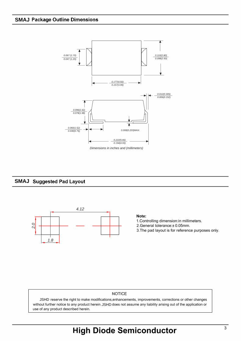
SMAJ
SMAJ
Dimensions in inches and (millimeters)
0.177(4.50)0.157(3.99)
0.110(2.80)0.098(2.50)
0.060(1.52)0.030(0.76)
0.222(5.66)0.194(4.93)
0.012(0.305)0.006(0.152)
0.008(0.203)MAX.
0.096(2.42)0.078(1.98)
0.067 (1.70)
0.047 (1.20)
4.12
2.0
1.8
4
H igh Diode Semiconductor
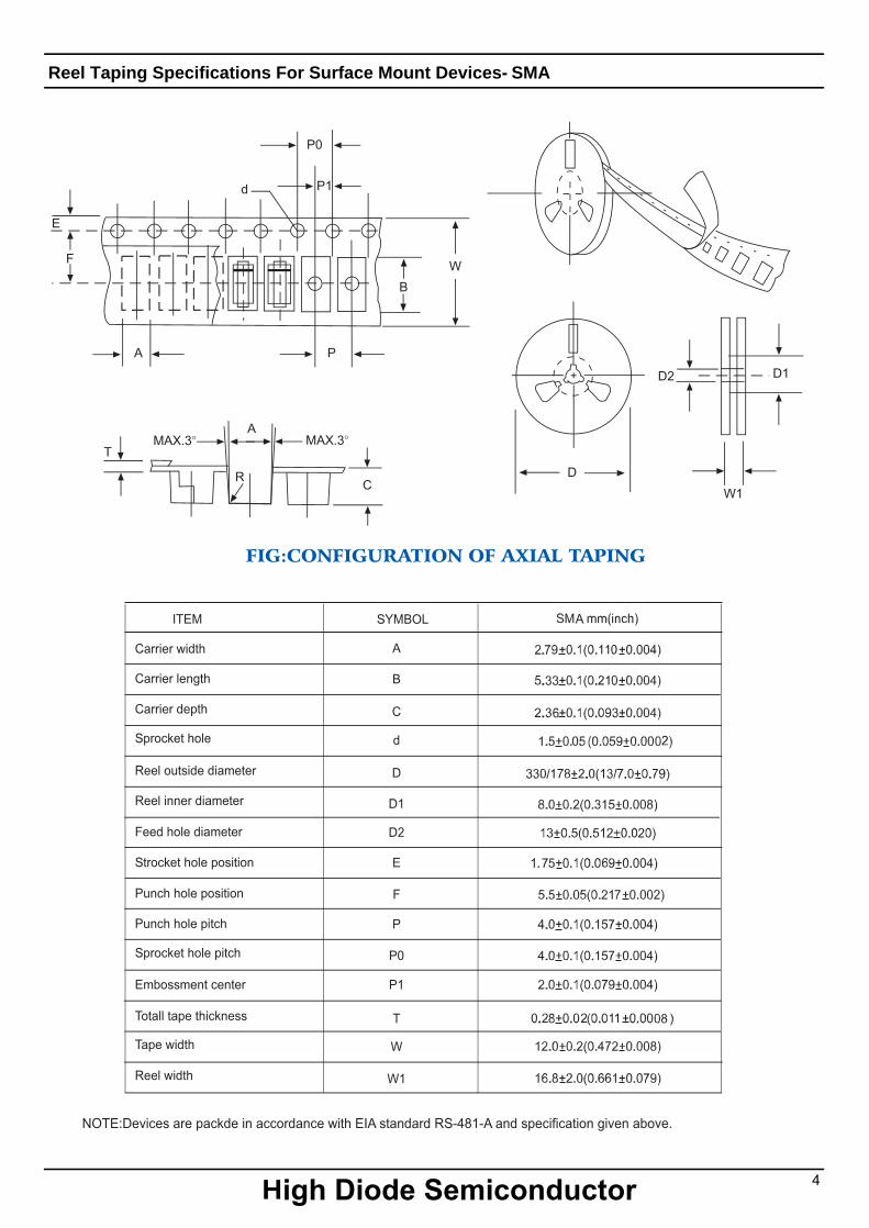
Reel Taping Specifications For Surface Mount Dev ices- SMA