![URINARY INCONTINENCE K21 .ppt [Read-Only]ocw.usu.ac.id/course/download/1110000119... · BPH with chronic retention Diabetic bladder neuropathy Complete parasympathetic lessions. Combined](https://static.fdocuments.us/doc/165x107/608dea5e8a631153654ba6a3/urinary-incontinence-k21-ppt-read-onlyocwusuacidcoursedownload1110000119.jpg)
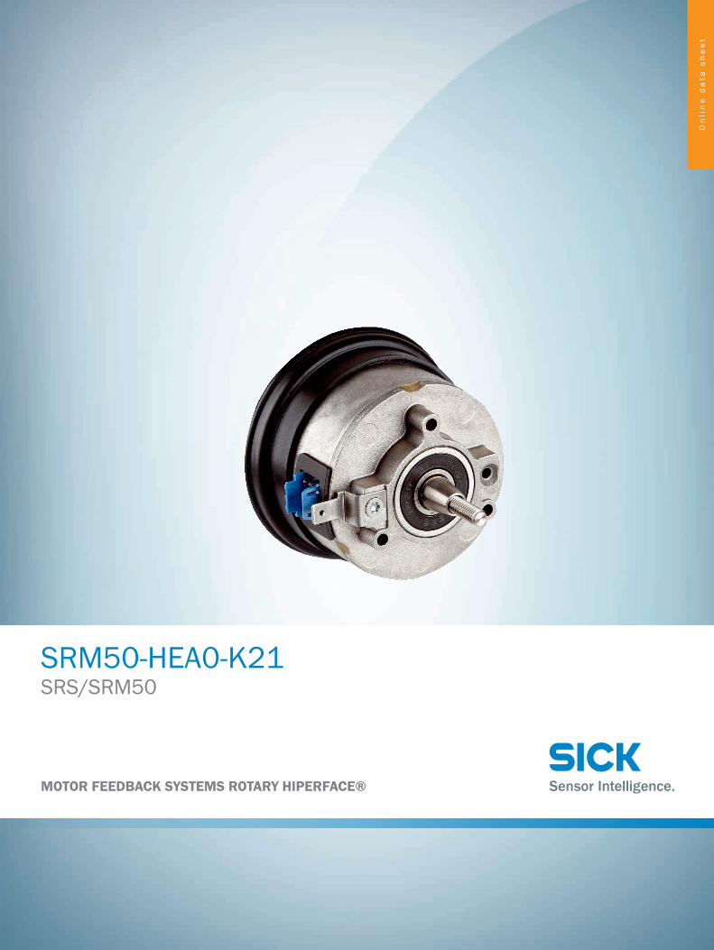
SRS/SRM50 SRM50-HEA0-K21, Online data sheet · SRM50-HEA0-K21 1037087 Other models and accessories ...
6
Online data sheet SRM50-HEA0-K21 SRS/SRM50 MOTOR FEEDBACK SYSTEMS ROTARY HIPERFACE®
Transcript of SRS/SRM50 SRM50-HEA0-K21, Online data sheet · SRM50-HEA0-K21 1037087 Other models and accessories ...
On
lin
e d
ata
sh
ee
t
SRM50-HEA0-K21SRS/SRM50
MOTOR FEEDBACK SYSTEMS ROTARY HIPERFACE®
ABCDEF
HIJKLMNOPQRST
SRM50-HEA0-K21 | SRS/SRM50MOTOR FEEDBACK SYSTEMS ROTARY HIPERFACE®
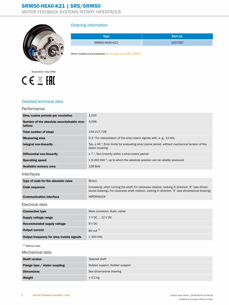
Illustration may differ
Ordering information
Type Part no.
SRM50-HEA0-K21 1037087
Other models and accessories www.sick.com/SRS_SRM50
Detailed technical data
PerformanceSine/cosine periods per revolution 1,024
Number of the absolute ascertainable revo-lutions
4,096
Total number of steps 134,217,728
Measuring step 0.3 ″ For interpolation of the sine/cosine signals with, e. g., 12 bits
Integral non-linearity Typ. ± 45 ″, Error limits for evaluating sine/cosine period, without mechanical tension of thestator coupling
Differential non-linearity ± 7 ″, Non-linearity within a sine/cosine period
Operating speed ≤ 6,000 min⁻¹, up to which the absolute position can be reliably produced
Available memory area 128 Byte
InterfacesType of code for the absolute value Binary
Code sequence Increasing, when turning the shaft For clockwise rotation, looking in direction “A” (see dimen-sional drawing), For clockwise shaft rotation, looking in direction “A” (see dimensional drawing)
Communication interface HIPERFACE®
Electrical dataConnection type Male connector, 8-pin, radial
Supply voltage range 7 V DC ... 12 V DC
Recommended supply voltage 8 V DC
Output current 80 mA 1)
Output frequency for sine/cosine signals ≤ 200 kHz
1) Without load.
Mechanical dataShaft version Tapered shaft
Flange type / stator coupling Rubber support, Rubber support
Dimensions See dimensional drawing
Weight ≤ 0.2 kg
2 MOTOR FEEDBACK SYSTEMS | SICK Online data sheet | 2018-08-03 21:46:18
Subject to change without notice
SRM50-HEA0-K21 | SRS/SRM50MOTOR FEEDBACK SYSTEMS ROTARY HIPERFACE®
Moment of inertia of the rotor 10 gcm²
Operating speed ≤ 12,000 min⁻¹
Angular acceleration ≤ 200,000 rad/s²
Operating torque 0.2 Ncm
Start up torque + 0.4 Ncm
Permissible movement of the drive element,static
± 0.3 mm radial± 0.75 mm axial
Permissible movement of the drive element,dynamic
± 0.1 mm radial± 0.2 mm axial
Angular motion perpendicular to the rota-tional axis, static
± 0.005 mm/mm
Angular motion perpendicular to the rota-tional axis, dynamic
± 0.0025 mm/mm
Life of ball bearings 3.6 x 10^9 revolutions
Ambient data
Operating temperature range –30 °C ... +115 °C
Storage temperature range –40 °C ... +125 °C, without package
Relative humidity/condensation 90 %, Condensation not permitted
Resistance to shocks 100 g, 10 ms, 10 ms (according to EN 60068-2-27)
Frequency range of resistance to vibrations 20 g, 10 Hz ... 2,000 Hz (according to EN 60068-2-6)
EMC According to EN 61000-6-2 and EN 61000-6-3 1)
Enclosure rating IP40, with mating connector inserted (according to IEC 60529)
1) The EMC according to the standards quoted is achieved when the motor feedback system is mounted in an electrically conductive housing, which is connected tothe central earthing point of the motor controller via a cable screen. The GND-(0 V) connection of the supply voltage is also grounded here. If other shielding conceptsare used, users must perform their own tests.
Classifications
ECl@ss 5.0 27270590
ECl@ss 5.1.4 27270590
ECl@ss 6.0 27270590
ECl@ss 6.2 27270590
ECl@ss 7.0 27270590
ECl@ss 8.0 27270590
ECl@ss 8.1 27270590
ECl@ss 9.0 27270590
ETIM 5.0 EC001486
ETIM 6.0 EC001486
UNSPSC 16.0901 41112113
2018-08-03 21:46:18 | Online data sheet
Subject to change without notice
MOTOR FEEDBACK SYSTEMS | SICK 3
ABCDEF
HIJKLMNOPQRST
SRM50-HEA0-K21 | SRS/SRM50MOTOR FEEDBACK SYSTEMS ROTARY HIPERFACE®
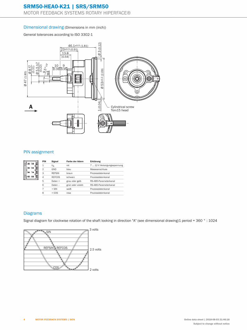
Dimensional drawing (Dimensions in mm (inch))
General tolerances according to ISO 3302-1Ø
8 f
7(0
.31
)
9.5
°±
3'
M4
Ø 4
7 (
1.8
5)
Ø 5
.5 h
7(0
.22
) 9(0.35)
10(0.39)
46.1±0.5 (1.81)
23±0.3 (0.91)
13.8(0.54)
Ø 3
(0
.12
)Ø
53
±0
.2 (
2.0
9)
Cylindrical screwTorx15 head1
(0
.04
)
A
PIN assignment
PIN Signal Farbe der Adern Erklärung
1 Us rot 7 … 12 V Versorgungsspannung
2 GND blau Masseanschluss
3 REFSIN braun Prozessdatenkanal
4 REFCOS schwarz Prozessdatenkanal
5 Daten + grau oder gelb RS-485-Parameterkanal
6 Daten – grün oder violett RS-485-Parameterkanal
7 + SIN weiß Prozessdatenkanal
8 + COS rosa Prozessdatenkanal
1 5
2 6
3 7
4 8
DiagramsSignal diagram for clockwise rotation of the shaft looking in direction "A" (see dimensional drawing)1 period = 360 ° : 1024
4 MOTOR FEEDBACK SYSTEMS | SICK Online data sheet | 2018-08-03 21:46:18
Subject to change without notice
SRM50-HEA0-K21 | SRS/SRM50MOTOR FEEDBACK SYSTEMS ROTARY HIPERFACE®
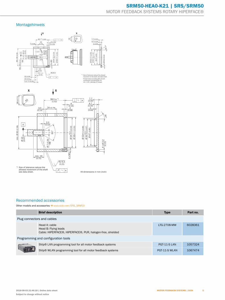
Montagehinweis
4 x
Ø 3
.2 (
0.1
3)
30
°
Ø 5
3 ±
0.2
(2
.09
)
Ø 5
0 +
0.1
(1
.97
)–
0.2
7.4 +0.2 (0.29)
3.4 –0.2
(0.13)
0.4(0.02)
Ø 4
7 (
1.8
5)
X
R3
18
(0.7
1)
Min
. 6
0 (
2.3
6)
42 ±*) (1.65)
X
7.7 (0.30)
4.7 (0.19)
1 (0.04)
Rz 6.3
4 x
M3
60
°
9.4
62°
–3
'
20(0.79)7 (0.28) 2 (0.08)
4 (0.16)
10 (0.39)
13 (0.51)
M4
Ø 5
4 +
0.2
(2
.13
)–
0.1
Ø 5
6 ±
0.1
(2
.20
)
Min
. Ø
8 (
0.3
1)
Ø 5
.5(0
.22
)
A*)
A*)
A1:3
Ø 6
.5(0
.26
)
*) Size of tolerance reduce the allowed
movement of the shaft, see data sheet.
Thread holes according DIN 13 with
counterbore according DIN 76
min. 1.05 x diameter of thread.
*) A 38.5 ± *)
(1.52)
4(0.16)
2(0.08)
Ø 5
4–
0.1
(2
.13
)+
0.2
Ø 5
6±
0.1
(2
.20
)
4 x
M3
Rz 6.3(0.25)
min. 19(0.75)
min
. Ø
60
(2
.36
)
Ø 1
2(0
.47
)
Ø 7
(0
.28
)
H8
2.5(0.10)A
XX
7.7(0.30)
4.7(0.19)
1(0.04)
Ø 5
0–
0.2
(1
.97
)+
0.1
Ø 5
3±
0.2
(2
.09
)
Ø 4
7 (
1.8
5)
4 x
Ø 3
.2(0
.13
)
*) A
60
°
30
°
18
(0
.71
)
R3
*) Size of tolerance reduce the allowed movement of the shaft see data sheet.
20 (0.79)3.5(0.14)
All dimensions in mm (inch)
Recommended accessoriesOther models and accessories www.sick.com/SRS_SRM50
Brief description Type Part no.
Plug connectors and cables
Head A: cableHead B: Flying leadsCable: HIPERFACE®, HIPERFACE®, PUR, halogen-free, shielded
LTG-2708-MW 6028361
Programming and configuration tools
SVip® LAN programming tool for all motor feedback systems PGT-11-S LAN 1057324
SVip® WLAN programming tool for all motor feedback systems PGT-11-S WLAN 1067474
2018-08-03 21:46:18 | Online data sheet
Subject to change without notice
MOTOR FEEDBACK SYSTEMS | SICK 5
Onlin
e da
ta s
heet
SICK AG | Waldkirch | Germany | www.sick.com
SICK At A GlAnCeSICK is one of the leading manufacturers of intelligent sensors and sensor solutions for industrial applica-tions. A unique range of products and services creates the perfect basis for controlling processes securely and efficiently, protecting individuals from accidents and preventing damage to the environment.
We have extensive experience in a wide range of industries and understand their processes and require-ments. With intelligent sensors, we can deliver exactly what our customers need. In application centers in Europe, Asia and North America, system solutions are tested and optimized in accordance with customer specifications. All this makes us a reliable supplier and development partner.
Comprehensive services complete our offering: SICK lifetime Services provide support throughout the ma-chine life cycle and ensure safety and productivity.
For us, that is “Sensor Intelligence.”
WOrldWIde preSenCe:Contacts and other locations – www.sick.com