Sri Parameswaran, Co-design for COMP4211 HW/ SW Co-Design Sri Parameswaran University of New South...
58
Sri Parameswaran, Co-design for COMP4211 HW/ SW Co- Design Sri Parameswaran University of New South Wales Sydney, Australia
-
date post
18-Dec-2015 -
Category
Documents
-
view
218 -
download
0
Transcript of Sri Parameswaran, Co-design for COMP4211 HW/ SW Co-Design Sri Parameswaran University of New South...

Sri P
aram
esw
aran
, Co-
desi
gn fo
r C
OM
P42
11
HW/ SW Co-Design
Sri Parameswaran
University of New South Wales
Sydney, Australia

Sri P
aram
esw
aran
, Co-
Des
ign
@ C
OM
P 4
211
Outline of this part of the presentation
Behavioral Synthesis (revisited shortly only!)
HW/SW Co-Design Heterogeneous multi-processor systems
Application Specific Instruction set Processors
Matlab to HW/SW Solution Network on a chip Real Time Operating Systems
Sri P
aram
esw
aran
, Co-
desi
gn fo
r C
OM
P42
11
Behavioral Synthesis

Sri P
aram
esw
aran
, Co-
Des
ign
@ C
OM
P 4
211
Behavioral Synthesis
Given
If RTL then 60ns
If Behavioral then
mdcbaxf **)(
-** +
25ns+**
** +-
-
** +-
50ns
50ns

Sri P
aram
esw
aran
, Co-
Des
ign
@ C
OM
P 4
211
Issues
Specify in unambiguous language Schedule and Allocate Operations Minimize Hardware Minimize Interconnect network Minimize Power dissipation

Sri P
aram
esw
aran
, Co-
Des
ign
@ C
OM
P 4
211
Specification
Usually VHDL is used Allows IF-THEN-ELSE, WAIT, UNTIL,
FOR loops High level specification allowing several
implementations Need to specify objective
Area, speed, power May not be the most efficient
implementation Fast time to market

Sri P
aram
esw
aran
, Co-
Des
ign
@ C
OM
P 4
211
Functional Unit Allocation
Allocation of Adders, Multipliers etc Try to increase sharing (this might affect
the schedule) Sharing of functional units also increases
interconnect network, multiplexors etc Functional Unit Allocation performed in
isolation (without considering register allocation or scheduling) will lead to inefficient designs

Sri P
aram
esw
aran
, Co-
Des
ign
@ C
OM
P 4
211
+
Schedule
w = b + 2
u = c + w
v = w + 1
y = u + v
a = b + c
x = a + 3
+
+
b 2
w1
c
+b c
a
+
+
b 2
+
wc
w
+1
+u v
y
+b c
a
+
+u v
y1
x
u
v
3
3

Sri P
aram
esw
aran
, Co-
Des
ign
@ C
OM
P 4
211
Scheduling – contd…
w = b + 2
u = c + w
v = w + 1
y = u + v
a = b + c
x = a * 3
+
+
b 2
wc
+b c
a
*
+1
+u v
y1
x
3

Sri P
aram
esw
aran
, Co-
Des
ign
@ C
OM
P 4
211
Final Implementation
Usually RTL description which is then processed through synthesis toolset create a layout, or bit stream for FPGAs.
Inefficient than lower level synthesis, such as gate level or RTL, but improves speed of design and implementation
Not widely used, acceptability is still an issue
Several tools are/were available – such as Behavioral Compiler

Sri P
aram
esw
aran
, Co-
desi
gn fo
r C
OM
P42
11
HW/SW Co-Design

Sri P
aram
esw
aran
, Co-
Des
ign
@ C
OM
P 4
211
HW/SW Codesign Design Flow
Specification
Partition
Compile to Proc. Convert to HDL
Implement software Implement Hardware
Interface Synthesis

Sri P
aram
esw
aran
, Co-
Des
ign
@ C
OM
P 4
211
Cosyma Architecture
Co-processor Sparc
RAM
Cosyma contains both an ASIC and a SPARC

Sri P
aram
esw
aran
, Co-
Des
ign
@ C
OM
P 4
211
Register Allocation
As can be seen from the above diagram w and v can be shared u and a can be shared
w = b + 2u = c + wv = w + 1y = u + va = b + cx = a + 3
w bu
c
v
a

Sri P
aram
esw
aran
, Co-
Des
ign
@ C
OM
P 4
211
Cosyma ComparisonClock cycles used
Benchmark SW HW-SW tc % Speedup
Diesel 22,403 16,394 9.9 1.4
Smooth 1,781,712 1,393,525 49.6 1.3
3d 1,377 1,514 13.8 0.9
HW/SW Cosynthesis for Microcontrollers: Rolf Ernst, Jorg Henkel, Thomas Benner.,IEEE Design and Test, December 1993

Sri P
aram
esw
aran
, Co-
Des
ign
@ C
OM
P 4
211
Benchmark Special
features of
benchmark
Lines of
C code
in
HW/SW
Section
Speedup
Overall
Speedup
XILINX
clock
speed
(MHz)
PPR time
(hours)
Integer Square functional 74 17.1 15.8 6.25 0.7
Towers of
Hanoi
recursive 72 15.2 12.7 6.25 3.2
Heap Sort
Hardware 1
functional 196
15.1
2.6
1.5625 3.125
6.3 1.9
Hardware 2 memory 1.3 1.5625 6.6
Matrix
Multiplication
memory &
functional
127 8.3
4.4
1.5625 1.5625
3.7 2.6
Plumhall functional 153 3.5
3.5
4 4
5.6 1.7
Bubble Sort memory 111 2.3 2.1 1.5625 3.4
Sieve of
Eratosthenes
memory 206 1.7 1.7 1.5625 4.5
ASP Speedup Results – with 68K & Xilinx 4013
Sri P
aram
esw
aran
, Co-
Des
ign
@ C
OM
P 4
211
Why do these systems not give superior results?
To achieve a good partition between HW and SW we need information on the code
This information could be obtained by either profiling or estimating the time taken and the size of HW needed for a segment of code
The simplest task is to find the time taken on the software side of things
We can profile data with the program to get how long each segment takes how many times each segment executes

Sri P
aram
esw
aran
, Co-
Des
ign
@ C
OM
P 4
211
The Problems
Specification Still early days
Profiling Different values on differing architectures
Estimates The sizes and the speed changing slightly
can alter the whole make up of the partition

Sri P
aram
esw
aran
, Co-
Des
ign
@ C
OM
P 4
211
Heterogeneous Multi-Processor System
HeMPS strategy Input:
task data flow graph library of processor and communication link types
Output: synthesizes a distributed, heterogeneous multiprocessor
architecture using a point-to-point network allocates subtasks to each processor provides a static task schedule

Sri P
aram
esw
aran
, Co-
Des
ign
@ C
OM
P 4
211
Introductory Example
Processor costs and subtask timesP0:P1: P2:Links:
3
2
4
1
12
12
43 4
3
P1P0
Total Cost: 4+2+1 = 7Total Time: 4
Given
Find a schedule
x, 3, 1, x1, 1, x, 34
2
1 18 1, 1, x, 3

Sri P
aram
esw
aran
, Co-
Des
ign
@ C
OM
P 4
211
Implementation Cost CPU Time (sec)
example #subtasks period HeMPS Wolf SHEMUS P&P HeMPS Wolf SHEMUS P&P
pp1 4 2.5 - 14 - 14 - 0.05 - 11
3 14 14 - 13 0.09 0.05 - 24
4 7 7 - 7 0.09 0.05 - 28
7 5 5 - 5 0.09 0.05 - 37
pp2 9 5 15 15 15 15 0.24 0.7 1.3 3732
6 12 12 - 12 0.16 1.1 - 26710
7 8 8 - 8 0.16 1.6 - 32320
8 7 8 7 7 0.18 1.0 1.1 4511
15 5 5 - 5 0.12 1.1 - 385012
cfuge 3 0.1 17 17 - - 0.08 0.1 - -
juice 4 0.1 27 41 - - 0.08 0.1 - -
dye 15 0.1 59 59 - - 0.83 7.2 - -
robot 25 20 14 - - - 1.55 - - -
23 9 - 17 - 1.55 - 7.3 -
Results

Sri P
aram
esw
aran
, Co-
Des
ign
@ C
OM
P 4
211
The biggest competitor - CPU!
YEARS
1000
1
10
100
CPU
VLSI
CPU performance has increased a 1000 fold in the last 15 years due to super scalar and super pipelined microprocessors.
VLSI - 10 times or less?
PE
RF
OR
MA
NC
E
Sri P
aram
esw
aran
, Co-
desi
gn fo
r C
OM
P42
11
Application Specific Instruction Set Processor
Sri P
aram
esw
aran
, Co-
Des
ign
@ C
OM
P 4
211
ASIPs
Application Specific Instruction-Set Processor Specifically designed for a particular application / a
set of applications (e.g. JPEG (cameras), Motion Estimation (video), MPEG4 etc)
Implement custom-designed instructions to improve performance of an application.

Sri P
aram
esw
aran
, Co-
Des
ign
@ C
OM
P 4
211
Advantages of ASIPs
Shorten Time-to-market Reduce Area Increase Performance Programmability
ASIC – ASIP – FPGA – GP (General Processor)Most Customised Least Customised

Sri P
aram
esw
aran
, Co-
Des
ign
@ C
OM
P 4
211
Xtensa® Processor
A configurable and extensible processor developed by Tensilica, Inc.
1. Selecting configurable core using Xtensa Processor Generator
2. Designing specific instructions using Tensilica Instruction Extension (TIE)

Sri P
aram
esw
aran
, Co-
Des
ign
@ C
OM
P 4
211
Xtensa® Processor Generator
Diagram is captured from [1]

Sri P
aram
esw
aran
, Co-
Des
ign
@ C
OM
P 4
211
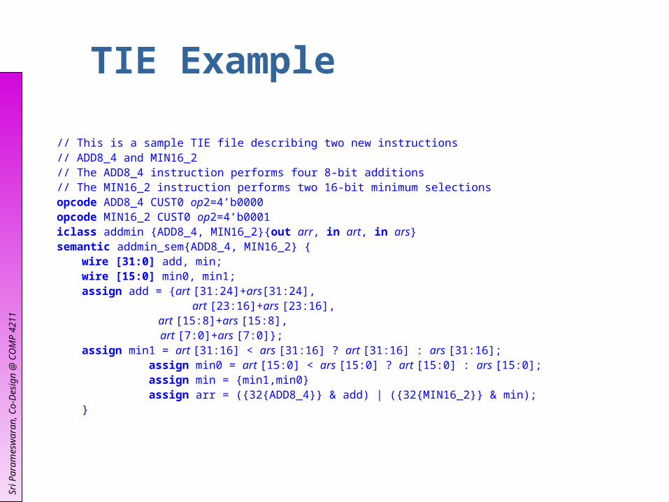
Tensilica® Instruction Extension (TIE)
The Tensilica® Instruction Extension (TIE) Language provides the designer with a concise way of extending the Xtensa processor’s instruction set.
A TIE description consists of basic description blocks to delineate the attributes of new instructions. TIE has the following description blocks: opcode – assigns opcodes and sub-opcodes to an
instruction. iclass – defines the assembly language syntax for a
class of instructions. semantic – defines the computations performed by an
instruction or a group of similar instructions etc
Sri P
aram
esw
aran
, Co-
Des
ign
@ C
OM
P 4
211
TIE Example
// This is a sample TIE file describing two new instructions// ADD8_4 and MIN16_2// The ADD8_4 instruction performs four 8-bit additions// The MIN16_2 instruction performs two 16-bit minimum selectionsopcode ADD8_4 CUST0 op2=4’b0000opcode MIN16_2 CUST0 op2=4’b0001iclass addmin {ADD8_4, MIN16_2}{out arr, in art, in ars}semantic addmin_sem{ADD8_4, MIN16_2} {
wire [31:0] add, min;wire [15:0] min0, min1;assign add = {art [31:24]+ars[31:24],
art [23:16]+ars [23:16], art [15:8]+ars [15:8], art [7:0]+ars [7:0]};
assign min1 = art [31:16] < ars [31:16] ? art [31:16] : ars [31:16];assign min0 = art [15:0] < ars [15:0] ? art [15:0] : ars [15:0];assign min = {min1,min0}assign arr = ({32{ADD8_4}} & add) | ({32{MIN16_2}} & min);
}

Sri P
aram
esw
aran
, Co-
Des
ign
@ C
OM
P 4
211
C program with TIE
#include <stdio.h>#include <stdlib.h>
int main() {// use ADD8_4 to add numbers// p = a+e; q = b+f; r = c+g; s = d+h;int a = 11; int e = 23;int b = 34; int f = 44;
int c = 12; int g = 22;int d = 34; int h = 41;x = ( a<<24 | b<<16 | c<<8 | d);y = ( e<<24 | f<<16 | g<<8 | h);z = ADD8_4(x,y);p = z >> 24q = z & 0x0F00;r = z & 0x00F0;s = z & 0x000F;
}

Sri P
aram
esw
aran
, Co-
Des
ign
@ C
OM
P 4
211
Performance
Diagram is captured from [1]

Sri P
aram
esw
aran
, Co-
Des
ign
@ C
OM
P 4
211
Xtensa® Performance Summary
Processor Architecture: 5-stage pipeline, 32-bit RISC
Instruction Set: Xtensa ISA with compact 16-bit and 24-bit encoding
Clock Speed: 350MHz in 0.13µ process 200MHz in 0.18µ process
Performance: 5X, 10X, and even 100X+ increases in performance
by extending the Xtensa processor with Tensilica Instruction Extension (TIE)
Size: Approximately 25,000 gates – base processor;
Power: 0.1mW/MHz in 0.13µ process @ 1.0V 0.4mW/MHz in 0.18µ process @ 1.8V

Sri P
aram
esw
aran
, Co-
Des
ign
@ C
OM
P 4
211
Method for Instruction Set Selection
Integer Programming Approach (Imai et al.[2]) Branch & Bound Algorithm (Alomary et al.[3]) Pattern Matching (Liem et al.[4]) Genetic Algorithm (Shu et al.[5]) Simulated Annealing Algorithm (Huang and
Despain[6]) Simulation of an application (Gupta et al.[7]) Performance Estimation of an application (Gupta
et al.[8])

Sri P
aram
esw
aran
, Co-
Des
ign
@ C
OM
P 4
211
Research Issues
For instruction set selection, research issues include:
Area of the instruction Power consumption of the instruction Performance improvement over the software Latency of the pipeline Reusability between applications Resource Sharing between instructions Coupling/decoupling of function calls Other components associate with the instructions
(such as specific register file for the instruction)

Sri P
aram
esw
aran
, Co-
Des
ign
@ C
OM
P 4
211
Tools
ASIP-Meister Academic uses only (free) http://www.eda-meister.org/asip-meister/
ARC (ARCtangent™) user-customisable 32-bit RISC core Commerical http://www.arc.com/products/arctangent.htm
Infineon Technologies . (Carmel™ architecture) Next generation wireless, broadband connectivity, DSP Commerical http://www.carmeldsp.com
Tensilica, Inc (Xtensa™) 5-stage pipeline, 32-bit RISC Commerical http://www.tensilica.com

Sri P
aram
esw
aran
, Co-
desi
gn fo
r C
OM
P42
11
Matlab to HW/SW

Sri P
aram
esw
aran
, Co-
Des
ign
@ C
OM
P 4
211
Simulink
• System simulation and modeling tool for performance evaluation and optimization
• Allows Matlab ,C, C++ algorithms be implemented into simulation models
• Supports Linear, nonlinear, continuous-time (Analog), discrete-time (digital) and mixed-signal systems
P/fdetect Sin
+ - 2
1
Input Frequency
Output Frequency

Sri P
aram
esw
aran
, Co-
Des
ign
@ C
OM
P 4
211
From Simulink to VHDL
Conversion utility bridges the gap between system level specification and RTL design
Two types of digital
circuits:
1. Control Logic (FSM)
2. Data Path Circuit
Simulink Model(.mdl file)
PerformanceEvaluation
Conversion Utility
VHDL(.vhd file)
Logic simulation
LogicSynthesis
Layout Place& Route

Sri P
aram
esw
aran
, Co-
Des
ign
@ C
OM
P 4
211
Control Logic Extraction
Stateflow :A tool within Simulink used for finite state machine design
Graphical representation using state diagrams
Each FSM represented by inputs, outputs, states and transitions
Increment
Entry: j ++
Hold
[J==8]
Module 1

Sri P
aram
esw
aran
, Co-
Des
ign
@ C
OM
P 4
211
State flow representation in VHDL
Each FSM is a separate entity Each state is represented in a case statement
If/Elsif block checks all transitions top-down
Junctions result in cascaded if/else statements
Else statement contains during actions for current state and all parents
Output is performed after success transition

Sri P
aram
esw
aran
, Co-
Des
ign
@ C
OM
P 4
211
Data Path Translation
Basic blocks in Simulink are directly mapped to its appropriate VHDL model
eg. Add, Sub, MAC Complex functions
implemented using a combination of simple models.
Multiplier , adder, switch
+
+
ADD
1UWBsignal
S18
MULTS12 REG
Z1
MUX
3
ConstantFIR filter
Coefficient
1Z
2
FIR Filter MAC datapath

Sri P
aram
esw
aran
, Co-
Des
ign
@ C
OM
P 4
211
Design Example – FIR Filter MAC
D
A
WEN
FIFO
Q
2
addr
wen
reset_acc
CONTROL
1
A
B
RESET
MAC
Z
Stateflow-VHDL
translator
Vendor SRAM
TAP_COEF
D
A
WEN
Q
Result
Vendor SRAM
3
Simulink -Datapath

Sri P
aram
esw
aran
, Co-
Des
ign
@ C
OM
P 4
211
Commercial Solutions
Xilinx System Generator™ for Simulink
Altera DSP Builder - Quartus II and MATLAB/Simulink interface
Bit-true and cycle-true Simulink library for common functions
Automatic HDL code generation from a Simulink model Maps design automatically to vendor specific IP core
library

Sri P
aram
esw
aran
, Co-
Des
ign
@ C
OM
P 4
211
Case Study- Texas Instrument DSP processors
Simulink Model(.mdl file)
PerformanceEvaluation
Texas Instrument Code Composwer Studio TM
Target specific Assembly code
C code (.mex file)
DSP CHIP Implementation
Design space exploration with Simulink Model
Simulink generated C code Translate down to TI processor
specific DSP instructions

Sri P
aram
esw
aran
, Co-
Des
ign
@ C
OM
P 4
211
Berkley IC design flow group SSHAFT
Bypasses data path translation by directly mapping Simulink’s primitives such as adders and switches into EDIF files
Simulink parameters are passed into circuit generators to produce circuits with corresponding parameters
Provides physical place/route and layout capability

Sri P
aram
esw
aran
, Co-
desi
gn fo
r C
OM
P42
11
Network on Chip

Sri P
aram
esw
aran
, Co-
Des
ign
@ C
OM
P 4
211
Network on Chip
SoCs are likely to be made up to several heterogeneous processing units (CPUs, DSP, FPGA)
Need communication architecture to cope with billion gate designs Orthogonalisation of concerns (separation
of communication and application) and platform based design
Reduction in design time => Faster time to market
Likely to contain complex interconnect

Sri P
aram
esw
aran
, Co-
Des
ign
@ C
OM
P 4
211
Why Networks?
More predictable electrical properties Promote reuse of components (get
components working from different domains)
Increased bandwidth Scalable

Sri P
aram
esw
aran
, Co-
Des
ign
@ C
OM
P 4
211
Conventional vs. Network
CPU
Memory
PHYMAC Processor
BasebandProcessor
CPU
Interface MAC Processor
PHY
BasebandProcessor
Conventional uP architecture A network architecture

Sri P
aram
esw
aran
, Co-
Des
ign
@ C
OM
P 4
211
Designing Network on Chips
Naïve approach Select a topology (mesh, torus, cube etc)
and protocol Does it meet constraints? If not, try
something different Large design space, often not optimal

Sri P
aram
esw
aran
, Co-
Des
ign
@ C
OM
P 4
211
Designing Network on Chips
One approach Pick an application HW/SW co-simulation to extract traffic behavior
Characterize traffic behavior (MPEG exhibits long-range dependence)
Optimize traffic for this behavior in mind (reduce contention by changing topology)
Make an initial estimate of design Select a set of parameters to vary based on
optimization goal (e.g. increasing buffers may decrease offered load)
Sri P
aram
esw
aran
, Co-
Des
ign
@ C
OM
P 4
211
Designing Network on Chips
Select a set of parameters to vary based on optimization goal (e.g. increasing buffers may decrease offered load)
Co-simulate design or use performance estimates to verify that design meets constraints
Iterate design until there are no more alternatives

Sri P
aram
esw
aran
, Co-
Des
ign
@ C
OM
P 4
211
Sonics Inc.
Components connect using OCP socket (common interface)
Bus based topology 2-level TDMA, round robin arbitration scheme.
Provides QoS using TDMA (slot reservation)
Choose a data path width and clock frequency to meet peak bandwidths.
Set pipeline to balance latency vs. targeted clock frequency

Sri P
aram
esw
aran
, Co-
Des
ign
@ C
OM
P 4
211
Sonics Design Flow
CoreGenerator
SOCCreator
•Connect and configure components, simulate and synthesize
•Simulate and analyze timing
•Configure to meet communication requirements

Sri P
aram
esw
aran
, Co-
Des
ign
@ C
OM
P 4
211
Research Areas
Fast simulation of networks Estimating performance
Automatic Synthesis of Interconnect Sizing of components
Smaller input buffers. Thinner buses. Smaller controllers. Result: smaller area and power consumption.
Flow control and Congestion management Power management

Sri P
aram
esw
aran
, Co-
Des
ign
@ C
OM
P 4
211
Summary
Network on Chip possible successor to bus architectures
Further work required to create tools for automatic synthesis and fast simulation

Sri P
aram
esw
aran
, Co-
Des
ign
@ C
OM
P 4
211
Summary of Path to implementation
To achieve the productivity necessary to create multi million gate designs we need a path to implementation from a high level specification
Several new methods are being investigated
A number of promising choices are becoming available
More work needs to be done to cover a wider possibility of choices

Sri P
aram
esw
aran
, Co-
Des
ign
@ C
OM
P 4
211
References [1] Xtensa® Microprocessor Overview Handbook For Xtensa® V (T1050) Processor Cores, Tensilica, Inc
2002 [2] Imai, M, Sato, J, Almoary, A, Hikichi, N, An Integer Programming Approach to Instruction
Implementation Method Selection Problem, 1992 [3] Alomary, A., Nakata, T., Honma, Y., Imai, M., and Hikichi, N., "An ASIP instruction set optimization
algorithm with functional module sharing constraint," presented at IEEE/ACM International Conf. on Computer-Aided Design, Santa Clara, USA, 1993
[4] Liem, C. May,T. Paulin, P: Instruction-Set Matching and Selection for DSP and ASIP Code Generation , European Design and Test Conference (ED & TC), 1994, pp. 31-37
[5] Shu, J., Wilson, T.C., Banerji, D.K., Instruction-Set Matching and GA-based Selection for Embedded-Processor Code Generation, 9th IC on VLSI Design, 1996
[6] Huang, I, Despain, A.M. Synthesis of application specific instruction sets, IEEE Trans. On CAD of IC & Systems, June 1995, Vol 14 Issue 6, pp 663-675
[7] Gupta, T. V. K., Sharma, P., Balakrishnan, M., and Malik, S., "Processor evaluation in an embedded systems design environment," presented at Thirteenth International Conf. on VLSI Design, Calcutta, India, 2000, pp. 98-103
[8] Gupta, T. V. K., Ko, R. E., and Barua, R., "Compiler-directed Customization of ASIP Cores," presented at 10th International Symposium on Hardware/Software Co-Design, Estes Park, US, 2002
[9] Benini L and De Micheli G, “Network on Chips: A New SoC Paradigm” [10] Varatkar G, Marculescu R, “Traffic Analysis for On-chip Networks Design of Multimedia Applications” [11] Lahiri K, Raghunathan A, Lakshminarayana G, “A Methodology for the Design of High-Performance
Communication Architectures for System-on-Chips” [12] Sonics Inc, “Sonics uNetworks : Technical Overview”,