S!rgonnt Ra na 1C.aboratlJl1!
85
ANL-6928 � .ANL-6928 ·- rgonnt Raonal aborat CONSOLIDATION AND FABRICATION TECHNIQUES FOR VANADIUM-20 w/o TITANIUM (TV-20) by / W. R. Burt, Jr., W. C. Kramer, R. D. McGowan, F. J. Karasek, and R. M. Mayfield DISTRIBION STATEMENT A Approved for Public Release Distribution Unlimited 2 0 0 2 0 3 2 0 1 0 5 \- _ __ __ _ _ ) - - - ___ ___ -
Transcript of S!rgonnt Ra na 1C.aboratlJl1!

ANL-6928 � .ANL-6928
·-
S!rgonnt Rational 1C.aboratlJl1!
CONSOLIDATION AND FABRICATION TECHNIQUES
FOR VANADIUM-20 w/o TITANIUM (TV-20)
by
/ ;/
W. R. Burt, Jr., W. C. Kramer, v-R. D. McGowan, F. J. Karasek,
and R. M. Mayfield
DISTRIBUTION STATEMENT A Approved for Public Release
Distribution Unlimited
20020320 105 \'------------_______ __ )
- - - -- ___ ___::_____ ___ ---"'

.... ...,. .. ,
LEGAL
'•
NOTICE This report was prepared as an account of Government sponsored work. Neither the United
States, nor the Commission, nor any person acting on behalf of the Commission:
A. Makes any warranty or representation, expressed or implied, with respect to the accu
racy, completeness, or usefulness of the information contained in this report, or that the use
of any information, apparatus, method, or process disclosed in this report may not infringe
privately owned rights; or
B. Assumes any l1ab111ties with respect to the use of, or for damages resulting from the
use of any information, apparatus, method, or process disclosed in this report.
As used in the above, "person acting on behalf of the Commission" includes any em
ployee or contractor of the Commission, or employee of such contractor, to the extent that
such employee or contractor of the Commission, or employee of such contractor prepares,
disseminates, or provides access to, any information pursuant to his employment or contract
with the Commission, or his employment with such contractor.
Printed in USA. Price $3.00. Available from the Clearinghouse for Federal
Scientific and Technical Information, National Bureau of Standards,
U. S. Department of Commerce, Springfield, Virginia

ANL;.692 8 @ Metal s , Ce ramic s ,
and Mater ial s (TID -45 0 0 , 4 1 st Ed, ) AEC (Re s earch and l g . Development Report) (j)
ARGONNE NATIONAL LABORATORY_ 9700 South Cas s Avenue Argonne , Illinois 6 0440
�
CONSOLIDATION AND FABRICATION TECHNIQUES FOR VANADIUM-20 w/o TITANIUM (TV- 2 0 ) 'I
b y :J.
W. R. Burt , Jr . , W . C . Krame r , _,. R. D . McGowan, F . J. Karasek,
and R. M . Mayfield
February 1 96 5 /O
Metallurgy Division Program 1 . 1 0 . 6
Portions of the material in thi s report have appeared in the following Metallurgy Divi sion Annual Report:
ANL- 6 86 8 ( 1 96 3 ) pp . 92 - 98
Operated by The Univers ity of Chicago under
Contract W- 3 1- 1 0 9 - eng-38 .@ with the
U . S . Atomic Energy Commis sion

TABLE OF C ONTENTS
Page
ABSTRAC T . . . . . . . . . . . . . . . . . . . . . . . . . . . . . . . . . . . . . . 9
I . INTRODUC TION. 9
II . PRELIMINARY ALLOY STUDIES l l
III . CONSOLIDAT ION . 15
A. Equipment . . . 15
B . Raw Material s 17
C . Proce s s Development . 18 l . Melting of Particulate Charge Material . 18 2 . Melting of Preconsolidated Charge Material 19 3 . Melting of Precompacted Particulate Charge Material . 21
D . Alloy Scale -up by EB and Arc Melting . 24
E. Ingot Evaluation . . . . . . . . . 2 6 l . ANL-produc ed Ingot s . . . . 2 6 2 . Commercially Procured Ingots 2 8
IV. PRIMARY FABRICATION BY EXTRUSION 3 0
A. Equipment . . . . . . . . 3 0
B . Proce s s Development . 3 3
C . Ingot Breakdown . . . . 34
D. Re- extrusion of Tube-blanks , Sheet-bar , and Bar 3 7
E . Product Evaluation . . . .
V . SECONDARY FABRICATION
A . Equipment . . . . . . . . . .
B . Cold Rolling of Bar , Rod , and She et
C . Tubing Fabrication Development l . Swaging Procedur e s . 2 . Ductile-core Drawing . . . . . 3. Plug Drawing . . . . . . . . . . .
D . Typical Tubing Production Schedule
E . Commercial Tubing Fabr ication.
VI . DISCUSSION . . . . . . . . . . . . . . . .
4 0
4 2
4 2
44
4 9 5 0 5 2 54
5 5
5 8
61
3

4
TABLE OF CONTENT S
Page
VII. CONCLUSIONS 63
APPENDICES
A. Purification of Vanadium by Ele ctron-beam (EB) Melting . 64
B. TV - 2 0 Inte r stitial Analys i s Methods and Re sult s . 66
C . Heat Treatment Studie s 68 l . Annealing Studie s . . 6 8 2 . Solution Annealing. . 74 3 . Pre cipitate Identifi cation 7 7
D. Mechanical -prope rty Tests . 8 0
ACKNOWLEDGMENTS 83
BIBLIOGRAPHY . . . . . 84

LIST OF FIGURES
No . Titl e
1 . Hardne s s Data for Rolled and Annealed Vanadium- Titanium Sheet a s Function of Titanium and Oxygen Content . . . . . . . 14
2 . Photograph of 60 -kW NRC Electron-beam Melting Furnace . 15
3 . Schematic Drawing of 60 -kW NRC Electron-beam Melting Furnace , Showing Particulate Feed Funnel in Pos ition in Place of Drip Rod . . . . . . . . . . . . . . . . . . . . . . . . . . 15
4 . Photograph of NRC (Model 2 721A) Arc-melting Furnace . 16
5 . Schematic Drawing of NRC (Model 2 721A) Arc -melting Furnace . . . . . . . . . . . . . . . . . . . . . . . . . . . . . . . . 17
6 . Vanadium Chips (A-1) and Titanium Sponge (A- 2 ) after Blending (B ) and Pres s ing into Briquet Form (C ) . . . . . 21
7 . A Se rie s of Vanadium- Titanium Pre s sed Briquets b efo re and afte r Welding to Form a Drip Rod for Electron-beam Melting . . . . . . . . . . . . . . . . . . . . . . . . . . . . . . . . . . . . 2 2
8 . Macro structure of Electron-beam- cast Vanadium- 2 0 w/o Ti-tanium Ingot (EB19 ) . . . . . . . . . . . . . 2 3
9 . E1ectron-beam.:.melted Ingot s o f TV - 2 0 24
10 . Arc - cast Ingot of TV- 20 (AM2 l ) . . . . 2 5
11. Transver s e Macro structur e of TV - 2 0 Arc - cast Ingot (AM2 l ) . 2 6
12 . Micros tructure of Transverse Section from T V - 2 0 Arc - cast Ingot (AM2 l ) . . . . . . . . . . . . . . . . . . . . . . . . . . . . . . 2 7
1 3 . Photograph of 318 - metric - ton (3 5 0 -ton) Lombard Vertical Extrus ion Pre s s . . . . . . . 3 0
14 . Tooling fo r 318 -metric - ton ( 3 5 0 -ton) Lombard Vertical Extrusion Pre s s . . . . . . . 31
15 . Photograph of 113 5 -metri c - ton ( 12 5 0 - ton) Lake Erie Horizontal Extrusion Pre s s . . . . . . . . . . 3 2
16 . Tooling Arrangement for 113 5 -metric - ton (12 5 0 - ton) Lake Erie Horizontal Extrus ion Pre s s . . . . . . . . . . . . . . 3 2
l 7 . Typical Surface Quality of V - 2 0w / o T i Extrusions after (a) Initial Ingot Breakdown Extrusion, and (b ) Re - extrusion into a Tub e -blank . . . . . . . . . . . . . . . . . . . 34
18 . Bille t Des ign for Tube -blank Extrusion 3 8
19 . Photograph of Billet Component s for Extrusion of V - 2 0w/oTi Tube -blanks . . . . . . . . . . . . . . . . . . . . . . . . . . . . . . . . . 3 8
5

6
LIST OF FIGURES
No . Titl e Page
2 0 . Die De s ign for Sheet -bar Extrus ion . 39
21. Longitudinal Micro structure of a V- 2 0w/o Ti Tub e -blank Extruded at 11 00°C and 13 : 1 Reduction Ratio (Extrusion No . 266 ) . . . . . . : . . . . . . . . . . . . . . . . . . . . . . . 41
2 2 . Photograph of 4, 5 5 0 -kg (10 , 00 0 -lb ) Fenn Drawbench . 43
23 . Photograph of Six- skewed- roll Mackinto sh-Hemphill Tube Straightene r . . . . . . . . . . . . . . . . . . . . . . . . . . . 43
24 . Longitudinal Micro structure of V - 2 0w/o Ti Sheet -bar Extruded at 12 0 0°C and a 13 : 1 Reduction Ratio (Extrus ion No . 2 81) . 44
2 5 . Longitudinal Mic ro structure s of 0 .15 - cm (0 . 0 6 0 - in . ) - thick V- 20w / o Ti Sheet (a) after Rolling ( � 65o/o cold work) and (b) after Annealing for 1 hr at 90 0 °C . . . . . . . . . . . . . . . 4 6
2 6. Longitudinal Micro structure s of 0 . 41 - cm (0 . 016 - in . ) - thick V - 2 0w/o Ti Sheet (a) afte r Rolling (� 70o/o cold work) , (b ) after Stre s s - r elieving fo r l hr at 7 00°C , and (c ) afte r Annealing for l hr at 90 0°C. . . . . . . . . . . . . . . . . . . . . . . . . . . . . . . . 4 8
2 7. Longitudinal Micro structure of Extruded V- 2 0w/o Ti Sheet-bar after Solution Heat-treatment for 15 min at l 30 0°C . . . . 49
2 8. Typical Die De sign for Ductile - core Drawing of V - 2 0w/o Ti Tubing . . . . . . . . . . . . . . . . . . . . . . . . . . . . . . . . . . . . 5 3
29. Typical Plug and Die De sign fo r Plug Drawing of V - 2 0w/o Ti Tubing . . . . . . . . . . . . . . . . . . . . . . . . . . . . . . . . . . . . . 54
30. Flow Sheet for Secondary Fabrication of V - 2 0w/oTi (TV- 20 ) Tubing . . . . . . . . . . . . . . . . . . . . . . . . . . . . . . . . . . . 5 6
31. Longitudinal Mi cro structure of As - drawn 0 . 48 - cm OD x 0 . 04 - cm Wall ( 0. 190 - in. OD x 0 . 016 - in . Wall ) V- 2 0w/o Ti Tubing , Cold -wo rked Approximate ly 67o/o from Last In-proc e s s Anneal . . . . . . . . . . . . . . . . . . . . . . . . . . . 59
3 2 . Longitudinal Micro structure of 0 .4 8 - cm OD x 0 . 04 - cm Wall (0 .192 - in . OD x 0 . 016 - in . Wall ) V - 20w/o Ti Tubing , Vac cum-annealed for 1 hr at 90 0°C . . . . . . . . . . . . . . . . . . . . . 6 0
3 3 . Photograph o f Variety o f V - 2 0w/o Ti (TV- 20 ) Tube Siz e s Produc ed at Argonne National Laborato ry . . . . . . . . . . 61
34. Diamond -pyramid -hardne s s Data on Heat - tr eated V - 20w/o Ti Having Various Amounts of Cold Work . . . . . . . . . . . . . . . . 6 8

LIST OF FIGURES
No. Titl e Page
3 5 . Longitudinal Micro structure of V - 20w/o Ti Cold-worked 2 5o/o and Vacuum-annealed for 1 hr at Various Tempe rature s . . . . 6 9
3 6 . Longitudinal Micro s tructure o f V - 2 0w/oTi Cold-worked 50o/o and Vacuum-annealed for 1 hr at Various Temperature s . . . . 7 0
3 7 . Longitudinal Microstructure o f V- 2 0w/o Ti Cold-worked 7 5o/o and Vacuum- anneal ed for 1 hr at Various Temperature s . . . . 7 1
3 8 . Longitudinal Mic ro structure o f V - 2 0w/o Ti Cold -worked 90o/o and Vacuum- annealed for 1 hr at Various Temperature s . . . 7 2
3 9 . Fr equency Di stribution of Microhardne s s Measurements on Individual Grains in a Sample o f V- 20w/o Ti Cold- rolled 7 5o/o and Vacuum-annealed for 1 hr at 7 50°C . . . . . . . . . 73
40 . Study of Recrystalli zation B ehavior of V - 20w/oTi as Function of Annealing Tempe rature by Distribution of Individual Grain Hardne s s e s . . . . . . . . . . . . . . . . . . . . . . . . . . . . . . . 74
4 1 . Longitudinal Microstructure s of As - extruded V- 20w/o Ti Sheet -bar after Solution Heat Treatment at Various Temperature s with Helium Cool or Water Quench . . . . .
42 . Microstructure of As - extruded V - 2 0w/o Ti Sheet -bar after Solution Heat Treatment for 3 min at 1 5 0 0°C Followed by
7 6
Water Quench; Hardne s s Measure s 249 DPH ( 2 2 Rc) . . 7 7
4 3 . Typical Micro structure of V - 20w/oTi after a 3 -hr Heat Treatment at 1 5 0 0°C and Ve ry Slow Cool ( 1 0 0°C eve ry 1 5 min) . . . . . . . . . . . . . . . . . . . . . . . . . . · . . . . . . 7 8
7

8
LIST OF TAB LES
No . Titl e Page
I . Fabricability Evaluation of Selected Niobium, Vanadium, and Zirconium Alloys . . . . . . . . . . . . . . . . . . . . . . . . 1 1
I I . Inters titial and Minor Element Content of Raw Mate rial s . 1 7
III . Hardne s s Reading s and Chemical Analys e s at Sele cted Locations along Two Ele ctron-beam - cast Vanadium-20 w/o Titanium ( TV- 20 ) Ingots . . . . . . . . . . . . . . . .
IV . Alloy and Inter stitial Element Analys e s from Thre e TV- 20
20
Arc - cast Ingots . . . . . . . . . . . . . . . . . . . . . . . . . . . . . 2 8
V . Alloy and Inter stitial Element Analys e s from Three T V - 2 0 Arc - cast Ingot s Procured from Union Carbide Corporation 2 9
VI . Summary o f Extrus ion Data for V - 2 0w/oTi ( TV - 2 0 ) Alloy 3 6
VII . Rod Rolling Schedule s . . . . . . . . . . . 42
VIII . Die Siz e s Used in Drawing V - 20w/o Ti Tubing 5 7
IX . Influenc e of Electron-beam Melting on Inte r stitial Content of Vanadium . . . . . . . . . . . . . . . . . . . . . . . . . . . . . . 64
X. Comparative Re sults of Interstitial Analys i s by ANL and Union Carbide . . . . . . . . . . . . . . . . . . . . . . . . . . . . . 6 6
XI . Re sult s o f Room-tempe rature Tensil e Te sts o n 0 . 1 5 - cm (0 . 0 60 - in . ) - thick V - 20w/oTi (TV-2 0 ) Sheet . . . . . . . . . . 8 0
XII . Re sults of Room - temperature Tensile Te s t s on 0 . 40 - cm ID x 0 . 0 4 - cm Wall (0 . 1 5 6 - in . ID x 0 . 0 1 7 - in.wall ) Tubing . . . . . . . . 8 1
XIII. Hydraulic Tube Burs t Te st Re sults for Fully Annealed Tubing . . . . . . . . . . . . . . . . . . . . . . . . . . . . . . . . 8 2

CONSOLIDATION AND FABRICATION TECHNIQUES FOR VANADIUM-20 w/o TITANIUM (TV- 20)
by
W. R. Burt, Jr. , W. C. Krame r , R. D . McGowan, F . J . Karas ek,
and R. M. Mayfield
� ABSTRACT sL. f Methods are pre sented cove ring a r"cently deVelo�
te�ology for the consolidation and fa'l?_Ei£�t!on�of �· :.£._<'!:_, �· and higll)1uality, smallt:i
.ameter ( <5 - mm) , thin-:van
(<0. 5 -mm) tubmgof a V-20w�o·TiJ_T..Y,_:;2�Q) alloy. Consohda-tion included electron-p�.§l-!!!���1- .:r:!!:�1ting of compacted vanadium c{Y-p and titanium sponge drip rods , followed by �-l!lelting of the .E.J?.J.:gggt . The arc - cast ingots were broken down by extrusion. She et-bar and tube-blanks were produced by a r e - extru sion proc e s s. Cold rolling of bar , rod, and sheet products was accomplished with little difficulty. Tube -blanks were cold-fini shed by swaging and drawing . The alloy showed a pronounced tendency to gall during drawing through carbide die s. This and other proc e s sing problems wer e over come , and high -quality tubing was produced in the de sired quantitie s. Additi\ral evaluation of the alloy included annealing and other heat - tre atment studie s and pe rtinent , room-temperature , mechanical-gr_��;rj:_y:_J:_�1:3t§3.. Industrial participation in the program has been encouraged, and early r e sults are reporte
_� �
J
I . INTRODUCTION
For s everal year s ther e has b e en an inc reasing need for information conce rning the pos sible u s e of vanadium or vanadium alloys as mate rials for fast - r eactor fuel- element cladding or jacketing. While conside rable effort has been devoted to studie s of the properti e s of vanadium and c ertain of its alloys , ( l ) evaluation of such materials as substitutes for stainle s s steel in fast reactor s was fir st r eported by Smith and Van Thyne in 1957. ( 2 )
The fast - reactor s e rvice demands imposed upon the cladding (and other structural components ) are rigorous , and not easily sati sfied by just any metal or alloy that happens to be popular at the moment. The mate rial should pos s e s s adequate high-temperature prope rtie s (including strength and integrity) , good the rmal conductivity, compatibility wi�h nuclear fuels
9

1 0
and with liquid-metal coolants , and stability under i rradiation, just to mention a few of the requirements. Finally, and pe rhaps of greate st importanc e (although most often negle cted or overlooked) the material must be fabricable into the de sired shape s , i .e . , high-quality , small -diameter , thin-wall tubing and/or related structure s.
Further studies of vanadium alloys were reactivated at ANL in early 1 96 3 - stimulated in part by the work of Okrent , (3 ) which indicated the relative importance of vanadium-base alloys for large , fast , power reactor s. Sufficient although limited quantitie s of vanadium-titanium alloys of various compositions were fi rst produced to gain some early ins ight into such characteri sti c s as compatibility with fuel and coolant , mechanical propertie s , and fabri.cability. The material was in all case s not the best from the standpoint of controlled alloy content and impuritie s; de spite thi s , the early results were encouraging . ( 4, 5, 6)
The above considerations prompted a furthe r and more complete evaluation of selected vanadium- titanium alloys of carefully controlled quality and campo sition. It be came nec e s sary, ther efore , to provide the wrought mate rial s de sired for further te sts of mechanical prope rtie s , fuel compatibility, sodium corrosion, and i rradiation behavior. Tubing fabrication techniques had to be es tablished for the alloy in orde r to provide highquality tubing for irradiation te sting and to insur e availability of TV - 2 0 tubing should it appear attractive for larg e - s cale usage.
Thi s report pre sent s the detail s of a fully inte grated consolidation and fabrication program having , as its end re sult , the delive ry of highquality TV - 2 0 bar , rod, sheet , and tubing for furthe r testing for r eactor s e rvice conditions by other s. While the fabrication of bar , rod, and sheet was r elatively easy and conventional methods were employed, consolidation and fabrication of the alloy into fini shed high-quality tubing r equired both conventional and developmental technique s .
Whethe r or not the se products survive the rigor s of te sting for ultimate reactor s e rvic e i s outside the s cope of thi s report. Naturally, our hope i s that the alloy will weather the storm; however , should it fail in some area , then pe rhaps the alloy will s e rve as a fir st-generation base refe rence that can be altered, pe rhaps by a te rnary addition, to overcome the pos sible shortcomings - thi s remains to be s een.
Before actual consolidation and fabrication operations are detailed, data obtained in preliminary alloy studie s are pre sented. Fabrication and product evaluation detail s follow , organized generally in the way in which the proc e s s ing was ac compli shed, i .e. , consolidation, primary fabrication, and s econdary fabrication. Data obtained as an adjunct to the main cour s e of work are included in the appendic e s. Industrial participation in the program has been stimulated, and the early re sult s , which are quite encouraging , are reported.

II. PRELIMINARY ALLOY STUDIES
The result s of a small- scale alloy fabricability study, car ried out in early 1 963, are summarized in Table I. The alloy ingredients were consolidated into buttons by ar c -melting pre cleaned material s. Most of the alloys* were jacketed in eithe r mild steel or Type 304 stainle s s steel to prevent contamination during hot rolling. The rolling practice was similar to that reported for foil production� (7 )
Table I FABRICABILITY EVALUATION OF SELECTED NIOBIUM, VANADIUM, AND ZIRCONIUM ALLOYS
(Not commercially available)
Alloy Composition Hardness Hot Rolling Hardness after Hot Cold Reduction
!Numerals Indicate w/o) as Cast Temp, °C Breakdown
Nb-5Mom NA(2) 1000 NA -25%
Nb-5Mom NA 850 NA 10% initially 30% after anneal
Nb-10Ti(l) 74-80 RB 850 75-77 RB 40% anneal then 50%
Nb-10V 20-21 Rc 950 2o-23 Rc Not Attempted
Nb-20V 28-31 Rc 1000 to 1150 - -
Nb-39V-1Ti 25-27 Rc 1000 to 1150 - -
Nb-9Ti-8V 96 RB 850 to 1150 - -
Nb-9Ti-3Mo(l) 75-79 RB 850 92 Rs 60%
Nb-15Ti-6V 87-90 RB 950 87-91 RB 50%
Nb-18Ti-4V(l) 85-90 RB 650 90 RB 68%
V-10Ti !TV-101(1) NA 850 lAir) NA 50% V-20Ti ITV-20)(1) NA 850-900 NA 50%
(Air)
V-40Ti 24-26 Rc 1050 20-24 Rc Not attempted
V-5Mo 94 RB 950 ss RB -
V-50Mo 28-36 Rc 1050 to 1150 - -
V-20 Nb-5Ti 30 Rc 1000 to 1150 - -
65V-35Nb IAS-5141 28 Rc 850 to 1150 - -
56Zr-28V-16Ti (AS-537) 41-43 Rc 1000 43 Rc -
(l)AIIoy coupons supplied to Engineering Corrosion Group for sodium compatability evaluation. (2)Not available. !31 Breakdown by hot rolling unsuccessful at temperatures indicated !Furnace limitation: 1150°Cl. (41Further hot rolling at higher temperature or high-temperature anneal required.
Hardness after Cold Reduction
93 RB
20-24 Rc
95 RB
-
-
-
98 RB 26-28 Rc
22-25 Rc 95 RB 21 Rc
-
-
-
-
-
-
Remarks
Some difficulty in cold working.
1125°C anneal dropped hard-ness to 91 RB.
Works well.
(4)
(3)
(3)
(3)
Works well.
To be annealed before further cold working. Works well.
Works well.
Works well.
Works well.
(4) Unable to cold-work without cracking.
(3)
(3)
(3)
(3) ll25°C anneal dropped hardness to 35 Rc.
*The alloys were generally of the solid- solution type , devoid of intentional additions of disper sions and/or pre cipitation-hardening elements.
1 1

1 2
The most fabricable binary alloys were Nb - lOw/oTi, V - lOw/oTi, and V- 20w/oTi; the more easily workable ternarie s were Nb - 9w/oTi-3w/oMo , Nb- 1 8w/oTi-4w/oV, and Nb - 1 5w/oTi- 6w/oV, on the basis of the methods and temperature s employed . Regarding the vanadium-titanium alloys , interstitial analysis of the 0 . 8 1 -mm-thick coupon stock yielded value s ave raging about 850 ppm oxygen and 500 ppm carbon for the V - 1 Ow/ oTi and 800 ppm oxygen and 450 ppm carbon for the V - 2 0w/oTi alloy .
The ease of workability of the vanadium-titanium alloys gene rally confirmed the earlier re sults reported by Smith and Van Thyne (2 ) even though different fabrication technique s were employed in the preliminary alloy studies , and even though the inter stitial contents of the final product were not given in the earlier report by Smith and Van Thyne , which was ANL- sponso red work conducted at IITRI (formerly Armour Re search Foundation).
As indicated by Note ( 1 ) at the bottom of Table I, ce rtain alloy coupons were submitted to the Engineering Corro sion Group for sodium compatibility evaluation at 6 50°C . The re sults indicated, in part , "that the vanadium-titanium alloys experienced a rate of weight lo s s le s s by about an orde r of magnitude than that apparently typical of niobium-bas e alloys expo sed under similar conditions . 11 ( 4)
The encouraging sodium-compatibility r e sults on the vanadiumtitanium alloys strengthened belief in the practicability of an alloy " scale - up" effort to provide the larger quantitie s of alloy stock ne eded for further evaluation s tudie s .
Howeve r , before any alloy 11 scale-up 11 was started, the previous fabricability re sults wer e confirmed and the effects of various titanium and oxygen contents were dete rmined in specimens made by using arc-buttonmelting procedure s e s s entially the s ame as before , but with clo s e enough control fo r the re sults to be meaningful and useful to the scale -up effo rt that was to follow .
Accordingly , s ome vanadium-titanium alloys were made from vanadium containing approximately 200 ppm of oxygen and some from vanadium containing approximately 1 30 0 ppm of oxygen. The carbon, nitrogen, and hydrogen wer e nearly the same in either case ( �400 , �2 50 , and �20 ppm , r e spectively). The titanium was from plate s tock having an inte rstitial content of �1 00 ppm carbon, �2 5 0 ppm oxygen, -20 ppm nitrogen, and rvl 0 ppm hydrogen.
The nominal titanium content of the alloys was 0 , 3 , 5 , and from 5 to 30 w/o in 5 -w/o increments . The ove rall melt weighed 60 to 70 g , but the initial alloy charge mixture was divided into two batche s weighing 30 to 3 5 g each .

A single batch was charged into a rectangular copper mold of a small nonconsumable-arc furnace. The system was thereupon evacuated, purged three time s with argon gas , and then evacuated and back-filled with a heliumargon gas mixture to a slightly po sitive pre s sure . The charge was melted into a small button, which was then cooled, flipped ove r , and remelted. Afte r a similar double melting of the s econd batch of the alloy lot, both buttons were broken up by cold rolling and recleaned, and both batches were recharged together into the furnace. Double melting again was us ed, with the final cast button measuring approximately 1 .2 x 3.8 x 3.8 em (0.5 x 1.5 x 1 .5 in.). Multiple melting and the combining of two buttons made from halfs ize batche s were nece s sary to obtain full-size buttons of adequate homogeneity. Each alloy lot was proce s s ed in the same manner.
The arc-cast buttons were individually jacketed in Type-304 stainl e s s steel for hot rolling. A coating of alumina was flame-sprayed on the jacket interior to prevent any inte raction, or bonding, b etween the button and the jacket. The jacketed alloys were hot-rolled with reductions of lOo/o per pas s and to a total reduction of approximately 75o/o, o r to a final thickne s s of about 0. 3 2 em (0. 1 2 5 in.). Hot-rolling temperature s ranged from 850 to 950°C , the higher temperature s being us ed for the higher titanium-content alloys. After the rolling , the alloys were r emoved from their stainl e s ssteel jacket s , cleaned, and vi sually inspected. The alloys were then coldrolled to a total reduction of 50 to 60o/o - to a thickne s s of 0. 1 6 em (0.063 in.) - with initial 5o/o reductions increased to lOo/o pe r pas s afte r some cold-work had been achieved. At this stage , the cold-rolled sheets were vacuum-anneal ed. The vanadium sheet was annealed for 2 hr at 800°C, while the titanium alloy she et was annealed for 1 hr at 900°C. Afte r annealing , the sheet stock was again cold-rolled to the final 0.0 8-cm (0.0 3 1 -in.) thickne s s (- 50o/o reduction) .
Hardne s s value s for the annealed and cold- rolled sheet , 0 . 16 and 0.0 8-cm thickne s s , r e spectively, ar e plotted as a function of titanium and oxygen content* in Figur e 1. The hardne s s of unalloyed vanadium i s markedly affected by oxygen content; thi s effect is dimini shed with titanium additions up to about 7 to 8 w/o. The hardn'es s decr ease in vanadium with small additions of titanium has been previously ob served and reported, including pos sible explanations. ( 8) Subsequent hardne s s increases with inc rea sing titanium content are credited to solid-solution hardening. Above 1 0 w/o titanium, the alloys showed a significant but uniformly small s ensitivity to diffe rence s in oxygen content of approximately 1000 ppm .
*The oxygen content shown in Figur e 1 i s e stimated to be somewhat higher than that of the starting materiaL While chemical analys e s wer e not obtained, it was as sumed that some increase in oxygen would occur in the multiple-arc melting operation, which was the same for all the alloys.
1 3

1 4
320 ,-------------------, 300 280
.., 260 g j 240 Q 220 ui
120 100
x COLD ROLLED 50% 0 ANNEALED
--- -300-500ppm 02 ---- -1300 -1500ppm 02
0o 10 15 20 25 30 35 NOMINAL Ti CONTENT, w/o
Figure 1
Hardness Data for Rolled and Annealed Vanadium-Titanium Sheet as Function of Titanium and Oxygen Content
The cold reduction produced a significant increase in hardne s s (work-hardening) for the vanadium and all the alloys. It appears to b e a uniform increase for all the range s of titanium content; however , the re is slight (perhaps insignificant) evidence that at titanium contents above 20 w/o , higher hardne s s e s may be expected. Additional studie s will be required to clarify this ob s ervation.
All the alloys were fabricated into high-quality sheet, the alloy containing 2 5 and 30 w/o titanium being the most difficult to fabricate . The se latter two alloys might prove difficult to fabricate into high-quality, small -diamete r , thin-wall tubing. The higher oxygen content did not affect fabricability measurably , although again the higher the titanium content the more difficult the fabrication . For vanadium alloys containing 1 0 w / o or more of titanium, an increase in oxygen content of 1 000 ppm appears to be equivalent in it s effect on fabricability to about a 5 -w/o increase in titanium content.
On the basis of preliminary data from the sodium cor ro sion evaluation of the various vanadium-titanium alloys, it appear ed that the cor rosion re sistance of the alloy increased with increasing titanium content. It was determined that at least 1 0 w /o titanium would be nece ssary to provide acceptable cor ro sion behavior. Pre sumably, the TV - 20 alloy would pos se s s adequate str ength, adequate sodium-corrosion resistance , and sufficient fabricability to insure production of the de sir ed products , including tubing. Vanadium alloys of le s se r titanium content, although not inve stigated so extensively, are believed to be fabricable by methods e s sentially similar to thos e r equired for TV - 2 0 alloy, but the fabrication characteristics and hardne s s of the 2 5- and 3 0 -w/o titanium alloys foretold potential difficultie s in producing high-quality, smalldiameter , thin-wall tubing of the s e highe r titanium alloys .
The enhanced intere st in TV - 20 as a fast- reactor cladding material , that followed this early work with the alloy, increased demands for wrought products , particularly tubing , for continuing irradiation, compatibility, and prope rty-evaluation studie s. The alloy "scale-up" from small arc-melted buttons to sizeable production ingots and the succe s sful fabrication into the de sired products are de scribed in the following sections of this report.

III. CONSOLIDATION
The cons olidation of the V- 20w/oTi (TV- 2 0 ) alloy was accomplished at ANL by means of electron-beam (EB ) and arc-melting (AM ). The melting points of both elements are above I600°C (29 l 2°F ) , and it is highly improbable that they could be more easily consolidated by other means .
A. Equipment
The NRC electr on-beam furnace pictured in Figure 2 , and shown schematically in Figur e 3, has a rated power output of 6 0 kW derived from a maximum beam current of 3 Amp and an accelerating potential of 2 0 , 000 V. A single gun supplie s the e lectron beam, which can be focused to melt either particulate s Syntron-fed from a hopper, or a solid drip rod. The water-cooled copper molds ar e of a bottomle s s de sign so that when melting is in progr e s s the ingot can be retracted downward. The furnace
106-7335
Figure 2. Photograph of 6 0 -kW NRC Electron beam Melting Furnace
106-7362
ROO FEED MECHANISM
UPPER FOCUS �
ELECTRON GUN \
OPERATORS SIGHT PORT
Figure 3. Schematic Drawing of 60-kW NRC Electron-beam Melting Furnace, Showing Particulate Feed Funnel in Position in Place of Drip Rod
15

16
chamber vacuum system maintains pre s sur e s of 10� 5 to 10-7 Torr during melting. A s e cond vacuum system maintains about the same pre s sure in the gun chamber , which is separated from the furnace chamber by an aperture plate . The remote gun and separate evacuation systems have proven to be very de sirable features. Gun power inte rruptions ar e infr equent during melting of gas sy products , and a minimum of gun maintenanc e is required.
The NRC (Mode l 2 7 2 1A) arc furnace shown in Figure 4, and schematically repre s ented in Figure 5, ha s a power supply providing up to 42 00 Amp for continuous consumable or nonconsumable melting . Particulate charge mate rial is Syntr on-fed as indicated. During consumableelectrode melting , the evacuation system maintains vacuums of approximately 1 o-3 Torr . During nonconsumable melting , the furnace chamber is maintained at a pr es sure of 250 Torr (argon gas ), so that an arc can be sustained between the tung sten tip of the nonconsumable electrode and the molten pool in the mold. The water-cooled copper molds are wrapped with magnetic s tirring coils for us e in promoting ar c stability and a refined ingot grain structure.
106 -7045
Figure 4. Photograph of NRC (Model 2721A) Arc -melting Furnace

ELE CTRODE DRIVE SCREW
WORM GEAR FOR DRIVE SCREWS
VIEWING PORT
FURNACE SHELL
SYNTRON PELLET FEED
1 06 -7787
WATER LINES- DRIVE ROD
WATER COOLED POWER
LEAD TO BUS
� CONSUMABLE ELECTRODE
POOL
Figure 5 . Schematic Drawing of NRC (Model 2721A) Arc-melting Furnace
B. Raw Materials
Based upon the r e sults of the preliminary s tudies on the V - 2 0 w/oTi (TV - 2 0) alloy ( s ee Figure 1 ) , the pre sumption was that no fabrication problems would be anticipated if the total inter s titialelement content of the alloy was held to low level s . Therefore , in choosing potential vanadium and titanium raw mate rial s , only those containing a minimum of inter stitial contaminants (C , 0, N, and H) were conside red in order to minimize pas sible effects on fabricability .
The pures t vanadium commercially available in large quantities at the outset of the program was in the form of -3 +2 0 me sh (U. S . s tandard sieve serie s ) chips from the Union Carbide Corp. of Niagara Falls , New York, at a cost of approximately $8 1/kg ( $37 /lb) .
Titanium of equal or higher purity was readily available and was procured as - 3 + 1 4 me sh sponge from
E . I. DuPont de Nemours and Co . at $5 . 2 0/kg ($2 . 40/lb). Limited quantitie s of 0 . 64 -cm (0 . 2 5 -in.) - thick titanium plate from the Chicago Development Corp. were us ed in some of the early consolidation ope rations . The typical inter s titial element analy s e s (C , 0, N, and H) for each of the s e materials ar e given in Table II.
Table II I NTERSTIT IAL AND MINOR ELEMENT CONTENT OF RAW MATERIALS
I nterstitial Element Content, Range in ppm Material
Carbon Oxygen Nitrogen Hydrogen Tota l
Vanadium Ch ips 400-450 200-500 100-500 0-10 700-1500 (Union Carbide)
Titan ium Sponge 30-300 60-400 20-45 5-45 115-790 (DuPont)
Titanium Plate 100 250 20 10 380(1) (Chicago Dev. Corp.)
(1) Range not determined.
1 7

18
Table II (Contd.l
Minor Element Content Amount Present, w/o
Vanadium Chips Titan ium Sponge (Union Carbide) (DuPontl
<2.0 p• <0.4 Zn <0.2 Mo.• Ta, W <0.1 As. Co, Hg, Ni , Si," Nb As, ea. • Hg, Ni." P <0.05 Zr <0.02 Ba, Ca. K
0.01 Fe, [Na] Fe 0.01-0.001 Mg,Mn Mg, Si
<0.01 Ag, AI, B, Bi, Cr, Cu. Ag, AI, B, Be, Bi, Co, Pb, Sb, Sn, Ti Cr, Cu, Li, Mn, Mo, Pb,
Sb, Sn, V, Zr <0.001 Be, Li, Sr
Symbols: " I nterference. []Accuracy uncertain.
C . Proc e s s Development
An alloy content of 2 0 ± l w/o titanium with an inter s titial content of :$1 000 ppm (C , 0, N, and H) was set as the target parameter . In addition, a fine equiaxed grain s tructure was de sired , with the cons olidated product being of s ound integrity . The methods us ed to obtain the se objective s are di scus sed in the following paragraphs .
l . Melting of Particulate Charge Material
Particulate charge material s were melted in both the EB and ar c furnace s in an attempt to evaluate the s e means of cons olidation. Vanadium chips were charged by vibratory (Syntron) feeding in both furnace s . Small ingots of vanadium we re obtained by both E B and arc melting , and s ome of this consolidated product was used in further te sting and proce s s deve lopment. The method, however , was gene rally cons ide red unsatisfactory because of a lack of suitable feed control . That i s , the rate at which the particle s are fed fr om the hopper can vary in a random manner that greatly complicate s the melting operation
Attempts to alloy by vibratory feeding were even more unsatisfactory becaus e of the difference s in dens ity, particle shape , and s ize of the two raw materials , combined with the more or le s s unpredictable feed rate . If the two materials could be pr eblended so that each pellet contained the de s ired alloy content (V - 2 0w/oTi ) , the re might be s ome promise for thi s method. The pr eblending technique was not attempted by particulate feeding, but was inc orporated into a succe s sful procedure that is di scussed later .
De spite the failur e by particulate feeding , early melting practice in both furnac e s c learly delineated the diffe renc e s in control

available for developmental proc edure s of thi s type . The cons tant vi sual ob se rvation of the proceeding s in EB- melting permits extensive control, while in arc melting one is e s sentially blind as to the behavior dur ing melting save for c ertain electrical indications . Viewing the arc pattern pr ovide s little s olac e so far as overall control i s c oncerned.
For the above reasons , fir st melting for alloying was thereafter carried out in the EB furnace . There we re advantage s in thi s procedure , as ide fr om the ea s e of operation: the vacuum dur ing melting (<lo-s Torr ) would insure that no contamination of the ingot would occur through pickup of inter stitial s during melting . By the same token, it was r ealized that vanadium and titanium would also vaporize with a po s s ible preferential los s of titanium.
While the purity of vanadium can be improved by a s erie s of EB melting operations ( s ee Appendix A) , such operations ar e time - consuming , can r e sult in large los s e s in vanadium, and can accordingly increase the cost of the pr oduct; the refore no special pur ification of the raw material was performed.
Because of the above-mentioned metal lo s s e s occurring dur ing pur ification experiments , EB melting rate s were held as high as pos s ible, consi stent with a sati sfactory pr oduct. It was noted early, however , that
1 9
gr o s s poros ity was evident in a s ingle melted E B ingot. This was clearly noted from X- ray radiographs of the ingot; ultrasonic te sting was not requir ed.
2 . Melting of Preconsolidated Charge Material
The s econd alloying te chnique involved the use of vanadium chips and titanium plate . Before alloying , vanadium chips we re cons olidated into 6 . 8 - cm (2 . 8 - in. ) - diameter ingot s (AM5 and 6 ) by nonconsumable arc melting , followed by remelting into 3 . 8 - cm ( 1 . 5 - in. ) - diamete r ingots in the EB furnace . In contrast t o particulate feeding , the drip - rod method c learly indicated a much improved c ontrol , largely because the mater ial dr opping into the molten pool generally was molten rather than in the form of s olid chip s .
An E B -melted vanadium ingot was wr apped with titanium sheet (rolled from the plate stock star ting material ) and EB drip -melted into a 3 . 8 - cm ( 1 . 5 - in . ) - diameter ingot. To promote homogene ity , the TV- 2 0 alloy was tripl e -melted (EB8 ) . Analys i s showed the ingot to vary in titanium content from top to bottom to such an extent that improvement was c onsidered nece s sary. There was s till s ome poros ity in EB8 after the three r emelts , but much les s poros ity than that found after a s ingle EB melt.
The third alloying method was bas ed on the use of vanadium chips and titanium plate , s omewhat as in the second method. Before alloying , the vanadium chips were cons olidated into a 3 . 8 - cm ( 1 . 5 - in. ) - diameter ingot by

2 0
electron-beam melting . Strips of titanium, sheared from the rolled plate , we re tack- welded along the length of the vanadium ingot to produce a compo s ite drip- rod for alloying in the EB furnac e . Four strips were us ed, repre senting 2 0% of the total drip- rod weight.
Chemical analys i s of the alloy ingot (EB 1 4R5 ) produc ed in thi s manner indicated that this ingot al s o was depleted in titanium at the top, and rich in titanium at the bottom, as before in the case of the wrap-around ingot (EBB ) . As s een in Table III, the titanium increased from 1 3 . 3 w/o at the top to 18 . 7 w/o near the bottom of the ingot. Thi s varianc e in titanium content was also ob served through hardne s s measurements taken along a milled flat on the ingot surface (Table III ) .
Table III
HARDNESS READINGS AND CHEMICAL ANALYSES AT SELEC TED LOCATIONS ALONG TWO ELECTRON- BEAM- CAST
VANADIUM- 2 0 w/o TITANIUM (TV- 2 0 ) INGOTS
Ingot EB 1 4R5 Ingot E B I 9 Cast from (Vanadium Ingot) - Cast from (Vanadium Chip ) -
(Titanium Plate ) (Titanium Sponge ) Briquet Drip -Rod Drip- Rod
Distance Hardne s s Analys i s Distance
Hardne s s from Ingot from Ingot Analysis
Bottom (em ) (DPH) (w/o Ti ) Bottom (em ) (DPH) (w/o Ti )
1 . 3 2 28 18 . 7 1 . 3 1 99 1 9 . 4 2 . 5 2 24 2 . 5 2 0 2 3 .8 2 1 3 3 .s·· 1 9 9 5 . 0 2 1 6 5 . 0 2 0 5 .6 . 3 2 18 6 . 3 2 1 5 7 . 5 2 02 7 . 5 2 02 8.8 1 9 2 1 6 . 9 8 .8 2 0 7
I 0 . 0 188 I 0 . 0 1 9 9 1 1 . 3 182 1 1 . 3 2 09 I 1 2 . 5 189 1 2 . 5 2 1 2 1 3 .8 186 1 3 .8 2 1 3 1 5 . 0 189 1 5 . 0 2 0 5 1 6 . 3 18 1 1 3 . 3 1 6 . 3 2 0 7
1 7 . 5 1 9 7 Hardne s s range = 18 1 - 22 7 18 .8 2 1 5 Mean hardne s s = 2 0 1 2 0 . 0 1 9 3 1 9 . 9
Hardne s s range = 1 9 3 - 2 1 5 Mean hardne s s = 2 05

The variance in titanium content re sulted from the method of drip- rod pr eparation (both wrap-around and welded strip s ) and subsequent dr ip- rod "melt- off" characteristic s of the e lectron beam. As the beam i s inclined at an angle o f 2 5° from the vertical, the beam initially points the end of the drip-rod, melting the outer material fir st. Mor e titanium than de sired is melted in initially pointing the rod.
A balanced melting rate between the vanadium and tita1;1ium was never achieved in the ingot by either of the s e methods . As a r e sult, the s e methods of EB drip- rod melting we re abandoned and a technique yielding the target homogene ity was s ought .
3 . Melting of Precompacted Particulate Charge Material
The fourth alloying method involved compaction of vanadium chips and titanium sponge into a suitable EB drip- rod. Batche s of I 00 g were weighed out ( 8 0 g of vanadium, 2 0 g of titanium) and individually pr e s sed at 6, 9 0 0 kg/cm2 ( 49 tsi ) into 3 . 2 - cm ( 1 . 2 5 - in. ) - diameter x 2 . 5 - cm ( 1- in. ) - long br iquets . The raw mater ials, blended mixture, and a pre s sed briquet are shown in Figure 6 . A ser ies of br iquets were welded together in an inert- atmos phere glovebox to form a drip- rod 50 to 7 5 em ( 2 0 to 3 0 in. ) in length. Figur e 7 shows the individual briquets and a completed drip- rod.
106 -7656
Figure 6
Vanadium· Chips (A - 1) and Titanium Sponge (A-2) after Blending (B) and Pressing into Briquet Form (C)
2 1

2 2
1 06 -7654
Figure 7 . A Series of Vanadium -Titanium Pressed Briquets before and after Welding to Form a Drip Rod for Electron -beam Melting
Three deve lopmental EB castings were made by the briquet dr ip- rod method. EB1 5 and 16 wer e 3 . 8 em (1 . 5 in . ) in diameter , while EB 1 9 was 5 . 8 em (2 . 3 in. ) in diameter . Chemical analyse s of all the ingots revealed that the titanium content was within (or very near to) the 2 0 ± 1 w/o limit . The chemical analys is re sults for EB19 (top and bottom) are pr es ented in Table Ill. The DPH value s (measured as for ingot EB1 4R5 in Section 2 above ) were indicative of a random di str ibution of titanium within a fairly nar row range . *
Figur e 8 shows a transver s e macros tructur e of the EB 1 9 cast ingot. The pr esence of unalloyed vanadium particle s pr obably r e sulted fr om piece s of s olid br iquet mate rial occasionally falling from the end of the drip- rod into the molten pool dur ing the melting ope ration. Thi s could result from insufficient mechanical bond in the TV br iquet. Apparently the molten pool s olidified before the fallen piece s became molten.
*While variation in hardne s s value s in an ingot can be affected by cooling rate and othe r factor s be s ide s titanium content, reading s along the length of a given ingot have proven to be of some value in locating areas in which the titanium content diffe r s s ignificantly from the mean.

Transverse Section
..,..--- Unalloyed vanadium
Macro 38491 1.3X
Figure 8. Macrostructure of Electron-beam -cast Vanadium-20 w/o Titanium Ingot (EB19)
A change in EB melting practice was used to m1mmize the pr oblem. If piece s of s olid metal wer e seen to fall into the molten pool, the driprod was retracted to stop further melting for about 3 0 to 60 s e c . During thi s time, the solid pie ces could di s s olve completely . While the proba-bility of finding unalloyed solids in the EB ingot was reduced, one cannot say that true homogeneity would exist after a s ingle melting operation of thi s type . Further , there was no indication that the change in EB melting practice eliminated poros ity or improved the surfac e quality .
At thi s stage of development, an arc - melting ope ration was counted on to improve alloy homogeneity , ingot soundne s s , and surface quality . The pr e s sure in the arc furnace ( 1 o -3 Torr ) might re sult in s ome inter stitial contamination of the alloy , but the degree of vacuum was not enough to caus e s ignificant vaporization of materials . By melting once in each furnace , the advantage s of both technique s could be utilized without compounding the disadvantage s of e ither method.
The above premise was te sted by combining EB ingots 1 5 and 1 6 into a consumable e lectrode and arc -melting into a 9 . 7 - cm (3 . 8 - in. ) - diameter mold (AM2 0 ) . The ar c-melted surface was considerably improved. Chemis try r e sults at three locations showed good homogeneity. Minor porosity was found only within the outer annular band of ingot material and appear ed to be entirely within the directionally- oriented grains . This minor porosity might be expected since rapid cooling of outer ingot surface by transfer of heat to the water - cooled copper mold cause s entrapment of gas e s within s olidifying metal in this r egion.
23

24
X - ray radiographs of the ingot showed no poros ity , but an ultrasonic inspec tion was not conducted. The ingot was sectioned longitudinally and the surface s macroetched. A uniform grain structur e was r evealed with no furthe r evidence of poros ity .
D. Alloy Scale - up by E B and Arc Melting
The " s cale -up" phase of the pr ogram was undertaken afte r a proven consolidation method had been e s tabli shed . It remained, however , to coordinate quantity and ingot s i ze s with the demands for TV - 2 0 wrought products . Of equal importance was matching the final arc - melted ingot s ize with extrus ion operations that were to follow.
Micro 38372 0 .2X Figure 9. Electron-beam-melted
Ingots of TV -20
It was c lear that a double-melting technique was required to produce a final ingot of suitable alloy homogeneity and soundne s s .
Early extrus ion s tudie s ( s ee page 34) als o were indicating that a double - extrus ion technique would be required to obtain an extruded product suitable for secondary fabr ication. The s e two requir ements were sati sfied by the following consolidation procedur e s .
For producing the large ingots r equired for furthe r fabrication, s ix br iqueted and welded 7 6 - cm ( 3 0 - in. ) - long drip- rods were EB-melted to produc e two 5 .8- cm (2 . 3 - in.)- diamete r x 5 1 - to 5 6 - cm (2 0 - to 2 2 - in. ) - long EB- melted ingot s . Throughout the EB- melting period, a melt chamber pre s sur e of <I o-s Torr was maintained. A power s etting of about 2 6 to 30 kW (approxi mate ly half of rated capacity) was used to effect a melting rate of approxi mately 6 0 g/min ( 0 . 1 3 lb/min). With this melt rate , a yield of about 9 5o/o was typical. Vaporization los se s vary inver s e ly with melting rate , othe r fac tor s being equal. Typical ingots are shown in Fig-ur e 9 . The casting surface was generally good, although no real effort was made

to control surface quality or to avoid internal poros ity. The main purpos e of EB melting was to provide alloy elec trode stock for arc melting .
Initially , the two E B ingots to be used as a consumable e lectrode for arc melting were machined and screwed together . Welding the ingots together under an inert gas was found to be a faster and more economical method. A typical c onsumable electrode was about 1 00 em (40 in. ) long and weighed about 1 6 kg (3 5 lb) . No difficulty was encountered in consumable- ar c melting of the electron-beam ingots into a 9 . 7 - cm (3 .8- in. )diameter , high-quality , arc - cast ingot. A melting rate of 1 kg/min was achieved by us ing s traight polar ity (consumable e lectrode negative) and 9 0 kW ( 3 , 0 0 0 Amp and 3 0 V) of power . The furnace chamber pre s sure throughout melting wa s 1 o-2 to 1 o-3 Tor r . A stirring c oil setting of 1 . 5 to 3 Amp aided arc collimation and grain refinement. The melting power was reduced in succe s s ive steps toward the end of the melt cycle. This procedure ( " hot- topping 11) promoted gradual solidification and minimized the cavity ("pipe11 ) that generally forms at the ingot top . E s sentially no charge mater ial was lost dur ing melting .
The ar c - cast ingots were radiographed upon removal from the arc furnace mold. They were then cropped at each end to r emove the s tarting plug from the bottom and the s econdary pipe (approximately 5 em [ 1 . 9 in.] long ) near the top . Cropped ingots were 27 to 33 em ( 1 1 to 1 3 in. ) long and weighed 1 2 to 1 4 kg (2 6 to 3 l lb) . A typical c ropped ingot is shown in Figure 1 0 . In general, ingot surface quality was exce llent and markedly improved over that obtained in the electron-beam furnace . Ingot hardne s s measur ed approximately 2 08 DPH.
,, 21 31 41 51 61 71 8 91 110 I I I 1\2. 1\ INCHES CENTIMETERS ARGONNE NATIONAL LABORATORY
I I l I I I I I 1101 I I I I I I I 12101 I I
Micro 38425 0.4X
Figure 1 0. Arc -cast Ingot of TV-20 (AM21)
2 5

2 6
E . Ingot Evaluation
1 . ANL- produced Ingot s
Evaluation of the arc - cast ingots inc luded visual, radiographic , and ultrasonic inspection, macr o- and microstructural examination, and chemical analys i s .
No defects normally were found in radiographs o f the ingots , except for the secondary piping near the ingot top a s pr eviously mentioned. Sample s for macr o- and microstructural examination were taken from the end cropping .
The transver s e macrostructure of arc- cast ingot No . AM2 l, as shown in Figure 1 1 , was typical of all three of the 9 . 7 - cm (3 .8- in. ) diameter ingots produced at ANL. Some radially - oriented solidification was evident in an annular band adjacent to the outer edge (circumference ) of the ingot, the remainde r o f the section exhibiting a typical fine , e quiaxed, grain structure . Minor poro sity in the ingots was found only within the outer annular band of ingot material and appeared to be entirely within the directionally - oriented grains , as mentioned earlier . Machining of the ingots fr om 9. 7 em ( 3 . 8 in. ) to the extrusion billet diameter of 9 . 0 em ( 3 . 5 in. ) did not completely remove thi s band of material containing pinhead- size porosity .
Macro 38446 lX Etchant: 5o/o AgN03, 2o/o HF (swab)
Figure 1 1 . Transverse Macrostructure of TV -20 Arc-cast Ingot (AM21)

An ultrasonic thr ough- transmis s ion inspection of the machined billets gave no indication of the pre sence of internal cracks , pore s , or inclusions . The minor poros ity exi sting near the billet surface was sub s equently removed in c onditioning the surface o f the bar after primary extrusion of the ingot, as will be discus sed later .
The as - cast microstructure of TV - 2 0 (AM2 l ) i s shown in Figure 1 2 . The matrix i s {3 s olid solution (vanadium-titanium), but the pr ecipitate phase has not been fully identified. (Additional information concerning pos s ible identity of the precipitate phas e i s included in Appendix A. )
/
\� \
Micro 38584 lOOX Etchant: lOo/o KOH, lOo/o K3Fe(CN)6
Figure 12. Microstructure of Transverse Section from TV -20 Arc-cast Ingot (AM21)
Chemistry sample s we re collected during the proce s s of machining the ingots to the primary extrusion billet diameter . Titanium and inters titial-element analyse s r e sults for thre e TV - 2 0 ingots are pr e s ented in Table IV . In general, the target alloy content ( 20 ± l w / o titanium) was achieved in each of the ingots. The total inter stitial contents ar e only s lightly above the target maximum of 1, 0 0 0 ppm. The analytical re sult s on AM2 l indicate that some preferential los s of titanium may have occurred dur ing proc e s s ing . Consequently 2 1 w/o of titanium was blended into the br iquet mixture s us ed to prepare drip- rods for subs equent ingots .
27

28
Table IV
A LLOY AND INTERS T I T IA L E LE MENT ANALYSES FROM THREE TV - 2 0 ARC - CAS T INGOTS
Element Analy s e s Ingot Numbe r and Pos ition Titanium Carbon Oxygen
(w/o ) (ppm ) (ppm)
AM 2 1 ( l )r op 2 0 . 2 ( 4 ) 3 8 7 3 6 0 Middle 1 8 . 7
Bottom 1 9 . 2
AM2 s ( 2 ) T op 2 0 . 0 3 42 39 5 Middle 1 9 . 9 Bottom 1 9 . 4
AM28 ( 2 ) Top 2 0 . 8 2 89 42 0 Middle 2 1 . 1
Bottom 2 0 . 1
( 1 ) 2 0 w/o titanium in E B melt charge briqu e t s . ( 2 ) 2 1 w/o titanium i n E B melt c h a r g e br ique t s .
Nitrogen (ppm)
2 7 0
3 7 9
2 9 1
( 3 ) For inte r s titial c ontent of r aw mate r ia ls , s e e Table II.
Hyd r ogen (ppm)
1
2 0
5 0
( 4 ) A hardne s s trave r s e taken a t 1 . 3 - c m ( 0 . 5 - in . ) inte rvals along the ingot length gave DPH r e adings ranging from 1 9 8 to 2 1 5 , th e mean value being 2 08 . (Compa r e with Table III. )
Total( 3 )
(ppm)
1 0 1 8
1 1 3 6
1 0 5 0
Analyse s on chip and sponge raw materials may vary s omewhat during a single batch or lot, and a var iation may be expected in analytical re sults , owing to sample preparation, surface cleanline s s , and the actual technique , per se ( s ee Appendix B ) . For the s e r easons , it i s not precis ely known just how much increase in inter s titial content is due to the actual proce s s ing and melting operations .
2 . Commercially - procured Ingots
In addition to the ingots pr oduced at ANL, three ingots wer e procured from Union Carbide Corporation (purchase orde r 445046) . The ingots , 1 0 . 2 -cm (4- in. ) diameter x 2 0 . 3 - to 2 5 . 4 - cm (8- to- 1 0 in. ) long , were produced by e s s entially the same proc e s s as that de scr ibed above for ANL-produced ingots (i . e . , c ompacted drip- rods were electron- beam melted, and the alloy ingots produced were subsequently arc - melted to ingots of the final diamete r ) . The two main difference s in technique were that longer s ections were compacted for drip- rods than the 2 . 5 - cm ( 1 - in. ) long ANL br iquets , and electron -beam ingots wer e quartered longitudinally for use as arc - furnace consumable electrode s , rather than be ing directly melted as whole EB ingots . The fir s t - mentioned change , made pos s ible by the greater pr e s s ing capacity available at Union Carbide , i s a de s irable one inasmuch as dr ip- rod preparation is simplified and expedited. The second change , made nece s sary by the comparatively large minimum EB ingot diameter that Union Carbide could cast , is unde s irable in that additional waste mate rial is g enerated , and proce s s ing time is increased .

The ingots were evaluated by means of macrosection examination, radiography, ultrasonic inspection, and chemical analys e s . Evaluation re sults indicated that the s e ingots were of c omparable quality to thos e produced at ANL. Analytical r e sults are summarized in Table V.
Table V
ALLOY AND INTERST ITIA L E LE MENT ANALYSES FROM THREE TV- 2 0 ARC - CAST INGOTS PROC URED FROM
UNION CARBIDE C ORPORATION
E lem ent Analy s e s
Ingot Numb e r Titanium( ! ) in P o s ition Carbon Oxygen Nitr ogen Hydr ogen
(w/o } (ppm) (ppm) (ppm ) (ppm )
7 6 1 - 1 T op 2 0 . 7 4 8 0 3 58 1 3 8 1 3 Middle 1 9 . 7
B ottom 1 9 . 0
7 6 1 - 2 T op 2 0 . 5 3 7 0 5 2 5 2 3 0 5 Middle 1 9 . 7 Bottom 1 8 . 8
7 6 1 - 3 T op 1 9 . 3 3 6 0 5 0 8 8 2 2 1 Middle 1 9 . 8 Bottom 1 9 . 4
( 1 ) AN L analy s i s for titanium.
Inte r s titial ele ment analy s e s w e r e s upplied by Union Carbide . UC and ANL inte r s titial e lement analy s e s a r e c o mpared in Appendix B .
T otal
(ppm)
9 8 9
1 1 3 0
9 7 1
29

30
IV . PRIMARY FABRICATION BY EXTRUSION
The only method used for hot -working the V - 20w/oTi (TV - 2 0 ) alloy was extrusion. No forging facilitie s were available at ANL, and the shaped roll pas s e s available were too small or of improper de sign.
A. Equipment
Two pre s se s were used for extruding the TV - 20 alloy: a 3 18-metric ton ( 3 50 -ton ) vertical pre s s , and a 1 1 3 5 -metric -ton ( 1 250 - ton ) horiz ontal pre s s . The 3 18-metric -ton ( 3 5 0 -ton ) vertical pre s s is shown in Figure 1 3 . The pre s s i s powered by a water accumulator system and is capable of de livering 272 metric tons ( 3 00 tons ) at a 38-cm/sec ( 1 5 - in.jsec ) extrusion speed. Nominal billet diameter s are 5. 1 or 6 . 4 em (2 or 2 . 5 in. ) . (All primary working of the TV- 20 alloy was done on a 5 . 1 - cm ( 2 - in. ) - diameter billet. ) An induction coil powered by a 30 -kW Tocco motor - generator unit was used for billet heating . Removal of the hot billet from the induction coil to the start of extrusion could easily be held within 8 to 1 0 s ec .
106 -7 043
Figure 13
Photograph of 318 -metric -ton (350-ton) Lombard Vertical Extrusion Press
The die de s ign shown in the tooling arrangement of Figure 1 4 was occas ionally u s ed. Ins ert die s (located inside the container ) were used for the most part to better ab sorb r adial stre s s e s impo sed on the die during extrusion and to reduce die cos t s .

STEM PRESSURE PLATE
TOOL
B U MPER PLATE
CONTAINER -----r?" /
PRESS HOUSING BASE
106-7048
D U M M Y BLOCK
F I LLE R P L ATE
'
� I
Figure 14
Tooling for 318-metric-ton (350-ton) Lombard Vertical Extrusion Press
The 1 1 35 -metric -ton ( 1 250 -ton) horizontal pre s s is shown in Figure 1 5 , and the tooling arrangement in Figure 16 . The pre s s i s de signed to extrude 1 0 . 2 - and 1 5 . 2 -cm (4- and 6- in. )-diameter billets and is capable of delivering a 908 -metric -ton ( 1 0 0 0 -ton) load at an extrusion speed of 25 em/sec ( 1 0 in.jsec ) . Extrusion billets were heated in a large siliconcarbide re sistance furnace capable of operation up to 1 500°C . A transfer
3 1

3 2
table from the furnace to the pre s s allowed transfer time s of approximately 20 sec. This pre s s is powered by the same water accumulator s ystem used for the smaller (3 18-metr ic -ton ) pre s s .
106-7 046
Figure 15. Photograph of 1135 -metric-ton (1250 -ton) Lake Erie Horizontal Extrusion Press
SHEAR
106 -7049
Figure 16 . Tooling Arrangement for 1135 -metric -ton (1250-ton) Lake Erie Horizontal Extrusion Press

B . Proce s s Deve lopment
As with all r efractory metal and alloys , the vanadium-titanium alloys are susceptible to contamination by inter stitial e lements at temperature s greater than 300°C. It was r easoned, therefore , that the mater ial should be protected against · contamination during heating and extrusion, unle s s the extruded product i s to be heavily conditioned to remove any contaminated surfac e laye r s . Based on this consideration, general practice at ANL r e quired " canning" the alloy in Type 304 stainle s s ste e l (or mild ste e l in certain cas e s ) to afford protection against contamination. This technique also permits the billet to be heated in air rather than in a vacuum or an inert atmospher e . The refore the 3 .8 -cm ( 1 . 5 - in . ) -diameter EB ingots were machined to 3 A-cm ( L 3 - in. ) diameter by approximate ly 7 . 6 - cm ( 3 - in. ) -long billet s , which were canned in T ype 304 stainle s s ste eL The component s were as s embled in an inert -atmo sphere g lovebox, wher e the end plug was TIG-welded to s eal the can. The overall (compo site ) billet size was 4 . 9 5 em ( 1 . 95 in. ) in diameter and approximate ly 16 em (6 . l in. ) long , with a partial 45° chamfer on the nos e end of the billet .
Extrus ion temperatur e s of 1 0 0 0 , 1 1 0 0 , and l 20 0°C wer e used in extruding the billets at a 7 : 1 r eduction r atio . At the lowe st extrusion temperature of l 0 0 0°C, the extrus ion pre s sur e s r equired indicated that high reduction r atio s could not be achieved. At l l 00°C , the extrusion pre s sure s indicated that adequate reduction ratio s (approximate ly 1 0 to 1 5 : 1 ) c ould be obtained consistent with acceptable character istic s of the extruded product. The micro structure of the bar extruded at l l 0 0°C showed a fine , r ecrystallized grain structure with uniform grain size along the complete length of the extrusion. At l 200°C, there was a tendency for a r eaction between the alloy and the Type 304 stainle s s - ste e l jacket mater ial, thus producing a poor surface on the extruded product. In addition, at thi s higher temperature , the degree o f mismatch between the hardne s s o f the alloy and the stainle s s - stee l j acket re sulted in poor contro l ove r dimensions . Based on the above considerations , l l 0 0°C was s e le cted as the be st extrusion temperature cons istent with adequate reduction r atio s and quality of the extruded product. (Later , a few production billets were extruded at 1 0 0 0 or l 20 0°C to confirm again the best extrus ion temper atur e . )
At all temper atur e s , r ippling of the alloy core occurred as r evealed by r adiography. This r ippling is a common phenomenon in the extrusion of a composite bar whose outer jacket material i s markedly s ofter than the inter ior core mater iaL T o correct this , the diameter of the core alloy was increas ed, ther eby r educing the r e lative amount of stainle s s ste e l pre sent in the can or jacket. When an alloy billet approximate ly 4 .4 em ( L 74 in. ) in diameter was used with a Type 304 stainle s s - stee l jacket measuring 4 . 9 5 - cm OD x 4A5 -cm ID ( 1 . 9 5 - in . OD x l . 7 5 - in . ID), no r ippling was experienced . Acc ordingly, this de s ign was e stab lished as 11 standard . "
3 3

34
All the exper imental extrus ions r evealed a surface having s ever e longitudinal striations , a s shown in Figure 1 7 . By using a double - extrusion technique , a surface quality was produced that minimized or e liminated the need for conditioning before cold finishing of the extruded product. The initial extrusion of an EB - or arc - cast ingot broke up the cast structure and refined the grain s iz e . At this stage , the longitudinal surface striations were removed in conditioning or machining the extruded product into billet s for r e - extrusion. The s e cond extrusion produced a surface greatly improved ove r the primary extruded surface , as shown in Figure 1 7 for the case of a tube -blank.
(a) Surface quality after initial extrusion.
(b) Surface quality after re-extrusion.
Micro 38929
Figure 1 7 . Typical Surface Quality of V -20w/oTi Extrusions after (a) Initial Ingot Breakdown
Extrusion and,
IX
(b) Re-extrusion into a Tube-blank
It was because of this surfac e str iation characteristic that the starting extrus ion billets had to be scaled up to a 9 . 7 -cm (3 .8- in . )- diameter ingot (see page 23 ) . The s e larger ingots would undergo a primary breakdown extrusion to a bar that, after conditioning, would yie ld a 4 . 4-cm ( l . 74 - in. )- diameter bar suitable for re -extrus ion into tube -blanks , sheetbar , rod, or other de sired shape s .
C. Ingot Breakdown
Arc - cast ingot s , 9 . 7 em (3 .8 in . ) in diameter , of V - 20w/oTi (TV - 20 ) produced at Argonne National Laboratory (AM2 l , AM25 , and AM28 ) , or pro cured from the Ste llite Divis ion o f the Union Carbide Corp. , Kokomo, Indiana (UC 76 l - l and UC 7 6 l - 3 ) , we re machined to a nominal diameter of

9 . 0 em (3 . 54 in. ) and to a length of 20 to 25 em (8 to 1 0 in. ) and were canned in Type 304 s tainle s s steel. The stainle s s stee l can measured 1 0 . 2-cm OD x 9 . 0 - em ID (4. 0 - in. OD x 3 . 5 5 - in. ID ) . The nose of the stee l can was par tially chamfered at a 4 5° angle . In an inert-gas g lovebox, the conditioned ingot was plac ed in the steel can, and the end plug welded in plac e . Billets were heated for 2 hr in a "Globar" furnace at the extrusion temperature of 1 1 0 0°C . (One billet was extruded at 1 0 00°C, but the extrus ion pre s sure s r equired indicated that a higher temperature would be mor e beneficial for subsequent extrusions . )
After heating, the billets wer e transferred to the extrusion pre s s and extruded at a speed of approximately 1 5 em/sec ( 6 in/s e c ) and with a MoSz -graphite - oil mixture for lubrication. The extrusion die s incorporated a 1 20° approach angle and were of H - 1 2 tool s tee l, heat -treated to a 4 7 - 50 Rc hardne s s . A graphite cut - off plug was placed behind the billet to provide complete extrus ion of the bille t . When nec e s sary, rough straightening was accompli shed immediately after extrusion.
After cooling , the bar was radiographed to determine the location of the TV - 20 core in the extruded bar . The s te e l ends wer e cropped from the extrusion, and the r emaining s te e l jacket was removed by machining . The TV - 20 bar was machined to the proper diameter for r e - extrus ion; in other words , the machining reduced the diameter approximately 0 . 3 em (0 . 1 2 5 in. ) and thus removed the striated surface caus ed by the initial extrusion of the ingot . The bar was then s ectioned to provide bille t s for r e extrusion measuring a nominal 4. 42 e m ( L 7 4 in. ) in diameter and approximate ly 1 1 . 5 to 1 2 . 5 em (4. 5 0 to 5 in. ) in length. The nos e of the billets wer e machined to a 1 20° inc luded angle to fit the cans for r e extrus ion. Solid billets were used for r e - extrusion into bar and sheet -bar stock. For tube -blank extrusion, a L 60 - em (0 . 6 3 - in. ) - diameter hole was drilled through the billet before finish-turning the outer surfac e .
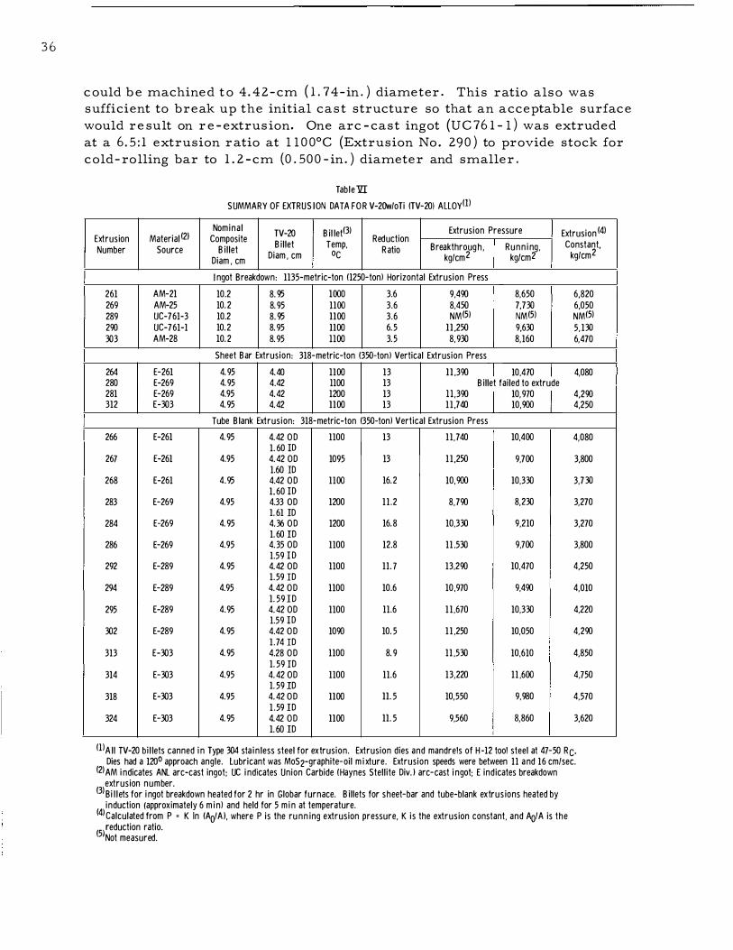
Data on extrusion of arc - cast ingot s are pre sented in Table V I . The extrus ion constants der ived from pre s sure s r equired to extrude arc - c ast ingots wer e s ignificantly higher than constant s obtained on r e - extrusion of the same mater ial undoubtedly, le s s effective l"qbrication accounts for part of the r e quired increas e in pre s sur e . As found in extrusion of other r e fractory metals and alloys , however , the initial deformation of a cast structure r equir e s greater effort than later hot -working operations .
Based on the calculated extrusion constants and a limiting stem pre s sure of 1 2 , 6 00 kg/ cm2 ( 180 , 0 0 0 psi ) , the maximum feasib le reduction ratio for extrus ion of an arc - cast ingot at 1 1 0 0°C would be about 7 : 1 . This reduction is sufficient to break up the initial cast structure and provide a material that will yie ld an acceptable surface quality on further extrusion or hot working . The lower extrusion ratio actually used for ingot breakdown (approximately 3 . 6 : 1 ) was based on the need for an extruded bar that
35
j
3 6
c ould b e machined t o 4. 42 -cm ( 1 . 74-in . ) diameter. This ratio also was sufficient to break up the initial cast structure so that an acceptable surface would re sult on r e - extrus ion. One arc - cast ingot (UC 76 1 - l ) was extruded at a 6 . 5 : 1 extrusion ratio at l l 0 0°C (Extrusion No . 290 ) to provide stock for cold- rolling bar to 1 . 2 - cm (0 . 500 - in. ) diameter and smaller .
Table1ZI
SUMMARY OF EXTRUS ION DATA FOR V-20w/oTi (TV-20! ALLOY(!)
Nominal TV-20 Bil let(3l Extrusion Pressure Extrusion (4) Extrusion Material (2l Composite Billet Temp, Reduction Constant, Number Source Billet Ratio Breakthrough , Runn ing ,
Diam , em Diam , em oc kg/cm2 kg/cm2 kg/cm2
I ngot Breakdown: 1135-metric-ton (1250-tonl Horizontal Extrusion Press
261 AM-21 10.2 8.95 1000 3.6 9.490 8,650 6,820 269 AM-25 10.2 8.95 1100 3.6 8.450 7.730 6,050 289 UC-761-3 10.2 8.95 llOO 3.6 NM(5l NM(5) NM(5) 290 UC-761-1 10.2 8.95 llOO 6.5 ll ,250 9,630 5,130 303 AM-28 10.2 8.95 llOO 3.5 8,930 8,160 6,470
Sheet Bar Extrusion: 318-metric-ton (350-tonl Vertical Extrusion Press
264 E-261 4.95 4.40 llOO 13 ll .390 I 10.41o I 4,080 280 E-269 4.95 4.42 llOO 13 Billet failed to extrude 281 E-269 4.95 4.42 1200 13 ll ,390 I 10,970 I 4,290 312 E-303 4.95 4.42 llOO 13 11 .740 10,900 4,250
Tube Blank Extrusion: 318-metric-ton (350-tonl Vertical Extrusion Press
266 E-261 4.95 4.42 OD 1100 13 11 ,740 10,400 4,080 1.60 ID
267 E-261 4.95 4.42 OD 1095 13 11 ,250 9.700 3,800 1.60 ID
268 E-261 4.95 4.42 OD 1100 16.2 10,900 10,330 3,730 1.60 ID
283 E-269 4.95 4.33 OD 1200 11.2 8,790 8,230 3,270 1.61 ID
284 E-269 4.95 4.36 OD 1200 16.8 10,330 9,210 3,270 1.60 ID
286 E-269 4.95 4.35 OD 1100 12.8 11 ,530 9,700 3,800 1.59 ID
292 E-289 4.95 4.42 OD 1100 11.7 13,290 10,470 4,250 1.59 ID
294 E-289 4.95 4.42 OD 1100 10.6 10 ,970 9,490 4,010 1.59 ID
295 E-289 4.95 4.42 OD 1100 11.6 11 ,670 10,330 4,220 1.59 ID
302 E-289 4.95 4.42 OD 1090 10.5 11 ,250 10,050 4,290 1.74 ID
313 E-303 4.95 4.28 OD 1100 8.9 11 ,530 10,610 4,850 1.59 ID
314 E-303 4.95 4.42 OD 1100 11.6 13,220 11 ,600 4.750 1.59 ID
318 E-303 4.95 4.42 OD llOO ll.5 10,550 9,980 4,570 1 .59 ID
324 E-303 4.95 4.42 OD llOO ll.5 9,560 8,860 3,620 1.60 ID
(!)All TV-20 bil lets canned in Type 304 sta in less steel for extrusion. Extrusion dies and mandrels of H-12 tool steel at 47-50 Rc. Dies had a 120° approach angle. lubricant was MoS2-graphite-oil m i xture. Extrusion speeds were between 11 and 16 em/sec.
(2lAM indicates ANL arc-cast ingot; UC indicates Union Carbide (Haynes Stellite Div.l arc-cast ingot; E indicates breakdown extrusion number.
(3)Bi l lets for ingot breakdown heated for 2 hr in Globar furnace. Billets for sheet-bar and tube-blank extrus ions heated by induction (approximately 6 m in) and held for 5 m in at temperature.
(4lcalculated from P = K In (AoiAl, where P is the runn ing extrusion pressure, K is the extrusion constant, and AQIA is the
(5/eduction ratio. Not measured.

As shown ear lier (Figur e 1 7 ) , the surface of a TV - 20 bar after ingot breakdown extrusion is characterized by deep longitudinal striations . As also mentioned, the s e striations were completely removed in conditioning the bar to the 4. 42 - cm ( 1 . 74- in. ) diameter for r e - extrusion. In some cas e s , the extreme lead end or nose of the TV - 2 0 bar did not c lean up at thi s diamete r . In such cas e s , the nose was machined until the surfac e striations were completely removed, and then cold - rolled into bar s tock of various s iz e s. In general, the yie ld of usable material for r e - extrusion was approximately 60o/o of the weight of the or iginal starting billet . Solid piece s from the lead and tail ends and chips generated in machining can be r e cycled to improve the yie ld o f recoverabl€ metal.
Sample s for metallographic examination from the lead and tail ends of an extruded bar revealed no observable micro structural change s along the length of the bar. Both sample s were recrystalliz ed and uniformly fine grained acros s the diameter.
Initially, billets for r e - extrusion, machined from extruded ingot stock, were nonde structive ly te sted by an ultrasonic through-transmis sion te st. No defects were observed in any of the billets so te sted. Sinc e there was no evidence that defects were being initiated in the breakdown extrusion operation, further te sting other than vi sual inspection was e liminated.
D. Re - extrusion of Tube -blanks , Sheet -bar , and Bar
The conditioned billets of extruded V- 20w / oTi (TV - 20 ) were r e extruded into bar , sheet-bar , and tube -blanks on the 3 18-metric - ton (350 -ton ) vertical extrus ion pre s s described ear lier . In all cas e s , the billets were canned in Type 304 stainle s s stee l to prevent contamination during heating and extrus ion. The bille ts , 4 . 42 em ( 1. 74 in. ) in diameter , were placed in a 5 . 1 - cm- OD x 4. 4 3 - cm-ID x approximately 1 6. 5 em- long ( 1 . 9 5 - in. OD x 1 . 7 5 - in. - ID x approximately 6. 5 - in. - long ) can. In the case of billets for tube -blank extrusion, an inner liner tube was incorporated into the billet as s een in Figur e s 18 and 1 9. This inner liner tube initially varied in s iz e , but eventually standardized t o a 1 . 5 9 -cm- OD x 1. 4 3 - cm-ID (0. 625 - in. - OD x 0 . 5 6 3 - in . - ID ) s iz e for extrus ion over a 1. 2 7 -cm (0 . 5 0 0 - in. ) tool- stee l mandrel. As before with billets for ingot extrus ion, an inert- atmo sphere glovebox was used for as s embling the components and making the end- plug c lo sure weld.
As s embled billets were preheated · in an induction coil to the extrusion temperature of 1 1 00°C (billets were also extruded at 1 0 0 0 and 1 20 0°C for comparison purpo se s ). Heating time s were approximately 5. 5 min with an additional 5 - min soak time at the specific billet temperature . The billets were manually transferred from the heating coil to the extrusion pre s s . A transfer time of approximate ly 1 0 sec to the initiation of extrusion normally e lapsed. As before , lubrication consisted of a MoSz -graphite - oil mixture .
3 7

38
Extrusion speeds were approximate ly 1 0 to 15 em/sec (4 to 6 in.jsec ) . The die s incorporated a 1 20° approach angle and were of H - 1 2 tool s te e l hardened to 4 7 to 50 Rc · The die s used for sheet-bar extrusion measured 0 . 63 x 2 . 54 em (0 . 1 2 5 x 1 . 00 in. ) , the specific die de s ign being shown in Figure 20 .
1 . 60 DIAM THROUGH AND
CONCENTRIC WITH OD
CLOSURE WELD AFTER ASSEMBLY;
LEAK- TIGHT
304 ss END PLUG
V - 20 w/o Ti B ILLET
ASSEMBLED BILLET
NOTE : ALL DIMENSIONS ARE IN CENTIMETERS
1 .59 OD X 1.431 ID 304 SS TUBING 304 SS JACKET AND ID LIN E R
Figure 18 . Billet Design for Tube -blank Extrusion
Micro 38930
3 04 SS Jacket with
V -2 0w/oTi Billet
Figure 19. Photograph of Billet Components for Extrusion of V -20w I oTi Tube-b lanks
�l/2X

I) MATERI A L IS H - 1 2 TOOL STE E L , HARDENED TO 46-48Rc 2) POLISH CONICAL ENTRY, RAD I U S , AND LAND 3) 30" ANGLE HOLDS ONLY AT CENTER LINE OF
SIDES; REMAINDER OF ENTRANCE CONE TO TAPER SMOOTHLY INTO 0.32 RADIUS
4) BREAK ALL SHARP EDGES
5) ALL DIMENSIONS ARE IN CENTIMETERS
Figure 20. Die Design for Sheet-bar Extrusion
Tube-blanks were extruded over a tool- stee l mandre l fabricated £::-om H- 1 2 tool steel and hardened to 46 to 5 0 Rc - The mandrel s iz e s were 1 . 1 4 or 1 . 2 7 em (0 . 45 0 or 0 . 5 0 0 in. ) in diameter , the latter size being more common. A floating -mandrel technique was used wherein the mandre l was he ld in the dummy block and the a s sembly placed in the billet before extrusion. A graphite -cut -off plug was located between the billet and the dummy block. Initial tube -blank extrusions were effected with a MoS2-graphite - synthetic oil mixture as a lubricant on the mandre l. However , extruded tube -blanks showed an irr egular and rough inner surface that was objectionable for secondary fabrication and difficult to r emove by conditioning . Later extrusions were effected with a pre - extrusion application of a glas s lubricant to the mandre l. The lubricant, which cons isted of a s lurry of Corning 7 0 5 2 glas s , water , and "Alignate , " was painted on the mandre l and oven- dr ied . At the billet extrusion temperature of l l 0 0°C, the glas s softened enough to act as a lubr icant during extrusion. This technique markedly improved the quality of the extruded inner surface and e liminated the need for mechanical conditioning before secondary fabrication. This is highly desirable s ince internal conditioning of an extruded tube -blank with an ID of ::::; 1 . 3 em (0 . 5 in. ) can prove both difficult and costly. Since the inner surface of the TV - 20 billet was protected by stainle s s steel, no prob lems with an alloy/glas s reaction were encountered.
After extrusion, the s tainle s s - stee l jacket on the external surface of the billet was r emoved by stripping . (The surface quality obtained on re - extrusion was shown ear lier in Figure 1 7 . ) At wor st , extruded products r equired only a light belt - sanding to condition the surface before coldworking operations . For tube -blank extrusions , the outer s tee l jacket was removed in a s imilar manner , while the inner stee l liner [approximate ly 0 . 4 mm (0 . 0 1 5 in. ) thick at thi s stage] was r emoved by pickling in a hot 3 5 to 5 0 v / o HCl solution.
39

40
Table V shows data obtained upon re - extrusion of TV- 20 into she et bar and tube -blanks . The re - extrus ion constant at 1 1 0 0°C i s approximate ly 4, 1 0 0 kgjcm2 ( 58 , 0 0 0 ps i ) . Thi s contrasts with a value of 3, 7 00 kgjcm2 ( 5 3 , 0 0 0 ps i ) for Type 304 stainle s s stee l extruded at 1 1 0 0°C under similar conditions of lubrication, die de s ign, and extrusion speed . For a limiting stem pre s sure of 1 2 , 6 00 kgjcm2 ( 1 80 , 0 0 0 psi ) , thi s average extrus ion constant of TV - 2 0 at l l 00°C cor r e sponds to a maximum reduction ratio of approximate ly 1 8 : 1 . The variation in the extrus ion constant i s rather high, and the reasons for thi s varianc e are unknown at thi s time .
Although the tooling dimensions var ied for many of the initial tube blank extrusions , conditions we re later s tandardized to an approximate 1 1 : 1 reduction ratio at 1 1 0 0°C when a l . 2 7 - em (0 . 5 0 0 - in . ) - diameter mandrel and an approximate l . 9 5 - cm (0 . 7 7 - in . ) -diameter die ar e used. After re moval of the stainle s s stee l and light conditioning of the surface , the dimens ions of extruded tube -blanks were appr oximate ly 1 . 8 0 - cm OD x 1 . 2 5 -cm ID (0 . 7 1 0 - in . OD x 0 . 490 - in . ID) , with s ome 1 . 9 3 - cm OD x 1 . 3 1 - cm ID (0 . 760 - in . OD x 0 . 5 1 5 - in. ID ) .
E . Product Evaluation
Although no nonde structive tes ting was performed on bar or sheet bar extrusion s before secondary fabrication, extruded tube -blanks we re inspected thoroughly a t the onset o f the program. After dejacketing and light vapor -blasting operations , extruded tube -blank surface s were carefully examined under a low- power microscope , and the inner surfac e was inspected with a bore scope . The tube -blanks were then lightly belt - sanded on the outer surface (if sanding was required ) and s ent to the Nonde structive T e sting Group for an ultrasonic examination . The re ject level was set for defects in exc e s s of l Oo/o of the wall thickne s s . Most extruded tube -blanks were of good quality although, initially, the rough inner surfac e made it difficult to inspect the tube to the l Oo/o defect leve l . With the adoption of the gla s s coating on the mandre l, the inne r surface was sufficiently improved to insure re liable nonde structive te sting at the required defect level . Short lengths from the lead end and the tail end of the tube blank were generally re jected s ince the ends were where most of the defects we r e located and where the " extrusion defect " (nonuniform deformation ) occurred.
The typical micro structure of an extruded tube -blank is shown in Figure 2 1 . This i s a longitudinal s ection of a tube -blank extruded at 1 1 0 0°C and a 1 3 : 1 r eduction ratio (Extrus ion No . 2 6 6 ) . The tube -blank has a re crystalliz ed and uniformly fine - grained structure . A minor amount of partic le s aligned in the extrus ion direction as 11 stringer s 11 can be s een. (The se str ing e r s we re also pre s ent in the micro structure of extruded she et bar . They had no directional effect on the propertie s of finished sheet , a s di scussed in Appendix D. ) N o mic ro structural var iations were obs e rved

along its length. Hardne s s measurements on the as -extruded tube -blank averaged 206 DPH (9 3 RB ) compared with 208 DPH (9 4 RB ) for the arc cast ingot.
Micr o 38 746 1 50X
Etchant: l Oo/o KOH, l Oo/o K3Fe (CN )6 Figure 21. Longitudinal Microstructure of a V-2 0w/oTi Tube-blank Extruded
at ll00°C and 13:1 Reduction Ratio (Extrusion No. 266)
4 1

42
V. SECONDARY FABRICATION
Bar, r od, and sheet of various thickne s se s were fabricated in a fairly conventional manner by c old- rolling extruded bar or sheet-bar products . Tubing fabrication utilized swaging and drawing operations on extruded tube-blanks . Tube s inking was avoided to a s sure final quality .
A . Equipment
Four rolling mill s were used in fabricating bar, r od, and she et products of V- 2 0w/oTi (TV- 2 0 ) . A 23 - X 4 1 - cm ( 9 - X 1 6 - in. ) , two-high, United mill was used for rolling bar and rod stock. A small, 8 - x 1 3 - cm (3 - x 5 - in. ) , two-high Stanat mill was used to roll rods smaller than 0 . 82 em (0 . 323 in . ) in diameter . The pas s size s and reductions for each of the se mill s are shown in Table VII. A 4 3 - x 6 1 - cm ( 1 7 - x 24 - in. ) , two -high, United mill was used for initial c old breakdown of extruded sheet- bar to a 0 . 1 5 - cm (0 . 0 6 0 - in. ) thickne s s . A 1 5 - x 3 6 - x 3 0 - cm (6 - x 1 4 - x 1 2 - in. ) , four-high Blis s mill was used for additional cold- rolling of TV - 2 0 sheet to a 0. 04 - em (0 . 0 1 6 - in. ) thickne s s .
Table VII
ROD ROLLING SCHEDULES
Two-high United Mill 2 3 - x 4 1 - cm ( 9 - x 1 6 - in . )
Roll Pa s s La r g e - roll Pa s s e s
P a s s S i z e , Pe r c ent em (in. ) Reduction
1 3 . 8 1 ( 1 . 5 0 0 ) 1 2 ( 1 )
2 3 . 5 6 ( 1 . 4 0 0 ) 1 3 3 3 . 3 3 ( 1 . 3 1 0 ) 1 2 4 3 . 1 2 ( 1 . 2 3 0 ) 1 2 5 2 . 9 3 ( 1 . 1 5 5 ) 1 2 6 2 . 74 ( 1 . 0 8 0 ) 1 2 7 2 . 5 8 ( 1 . 0 1 5 ) 1 2 8 2 . 54 ( 1 . 0 0 0 ) 3 9
1 0 1 1 1 2 1 3 1 4 1 5 1 6 1 7 1 8
( ! ) Entering a 4 . 0 7 - c m ( 1 . 6 - in. ) bar . ( 2 ) Entering a 2 . 54 - c m ( 1 . 0 - in . ) bar . ( 3 ) Entering a 0 . 9 7 - c m ( 0 . 3 82 - in . ) b a r .
Two-high United Mill 2 3 - x 4 1 - c m ( 9 - x 1 6 - in . )
Small - r oll Pa s s e s
Pa s s S i z e , Pe r c ent em (in. ) Reduction
2 . 34 ( 0 . 9 2 0 ) 1 5 ( 2 )
2 . 1 6 ( 0 . 84 9 ) 1 5 1 . 9 9 ( 0 . 7 8 3 ) 1 5 1 . 8 3 ( 0 . 7 2 2 ) 1 5 1 . 6 9 ( 0 . 6 6 6 ) 1 5 1 . 5 6 ( 0 . 6 1 4 ) 1 5 1 . 4 6 ( 0 . 5 7 5 ) 1 2 1 . 3 7 ( 0 . 5 3 9 ) 1 2 1 . 2 8 ( 0 . 5 04 ) 1 2 1 . 2 0 ( 0 . 4 7 3 ) 1 2 1 . 1 2 ( 0 . 44 3 ) 1 2 1 . 0 7 ( 0 . 4 2 2 ) 9 1 . 0 2 ( 0 . 4 0 2 ) 9 0 . 9 7 ( 0 . 3 82 ) 9 0 . 9 1 ( 0 . 3 64 ) 1 0 0 . 8 9 ( 0 . 34 9 ) 8 0 . 8 6 ( 0 . 3 3 7 ) 7 0 . 82 ( 0 . 3 2 3 ) 8
Two-high Stanat Mill 9 x 1 3 em (3 x 5 in. )
Pa s s S i z e , Pe r c ent em ( in . ) Reduction
0 . 9 5 ( 0 . 3 7 5 ) 4 ( 3 )
0 . 8 6 ( 0 . 34 0 ) 1 7 0. 77 ( 0 . 3 0 5 ) 2 0 0 . 6 9 ( 0 . 2 7 0 ) 2 2 0 . 6 1 ( 0 . 2 4 0 ) 2 1 0 . 5 5 ( 0 . 2 1 5 ) 2 0 0 . 5 0 ( 0 . 1 9 5 ) 1 7 0 . 44 ( 0 . 1 7 5 ) 2 0 0 . 4 0 ( 0 . 1 5 7 ) 2 1 0 . 3 6 ( 0 . 1 4 0 ) 2 1 0 . 3 2 ( 0 . 1 2 5 ) 2 0

Three Fenn swagers ( l F, 2 F, and 3 F) , two hydraulic drawbenche s , and a tube straightene r were u s e d in the cour se of tubing fabrication. The draw benches we re of 2 , 2 70 - and 4 , 5 5 0 -kg ( 5 , 0 0 0 - and 1 0 , 00 0 - lb) capac itie s . The larger drawbench is shown in Figure 2 2 . The straightener , shown in Figure 23 , i s capable of handling tubing of 0 . 3 - to 1 . 3 - cm ( 0 . 1 2 5 - to 0 . 5 0 0 - in . ) diamete r .
1 06 -7 042
Figure 22. Photograph of 4,550-kg (10 ,000-lb) Fenn Drawbench
40248
Figure 23. Photograph of Six-skewed-roll Mackintosh-Hemphill Tube Straightener
43

44
TV- 20 pr oducts were annealed or str e s s re lieved in two furnace s , both of which were re s istance -heated and capable of maintaining vacuums of l 0 - 5 Torr at temperature s up to about l l 0 0 °C . The normal time to reach temperature afte r pump- down ave raged about l . 5 hr for each furnace .
B . Cold Rolling of Bar , Rod, and Sheet
Afte r removal of the stainle s s - steel jacket from a TV- 20 ingot extrus ion (Extrus ion No . 2 9 0 , s ee page 3 6 ) , the heavily striated surface was removed by machining to a 3 . 3 - cm ( 1 . 3 - in. ) diamete r . One small piece of the machined bar was cold- rolled to a diameter of 2 . 62 em ( l . 0 3 in. ) ( 3 7% reduction in area) on the 2 3 - x 4 1 - cm ( 9 - x 1 6 - in. ) mill . This bar wa s annealed for 1 hr at 9 0 0 °C, nonde structive ly te sted, and de live red to the r eques tor .
The balance of the machined bar s tock wa s to be rolled and swaged to a diameter of 1 . 2 7 em ( 0 . 5 0 in. ) , with an interm� diate vacuum anneal at a diameter of 2 . 1 5 em ( 0 . 8 5 in. ) ( 5 7o/o reduction in area) . The fir s t pie ce rolled us ing thi s schedule split longitudinally before attaining the 2 . 1 5 - cm diameter . The s chedule was revised s o that the material was rolled to a 2 . 54 - cm ( 1 . 0 0 - in . ) diameter (4 l o/o reduction in ar ea) , vacuum- annealed , rolled to a 1 . 8 3 - cm (0 . 72 - in. ) diamete r (62o/o reduction in area) , annealed, and finish- rolled to the final diameter of 1 . 3 7 em ( 0 . 5 3 9 in. ) (4 3o/o reduction in area) . No cracking was encounte r ed when thi s schedule was followed. The rolled rods were swaged to the final 1 . 2 7 - cm ( 0 . 5 0 0 - in. ) diamete r . The swaging a l s o helped t o make the rods round and s traight. Finally, the mate rial was cleaned, nonde structively te sted , and given the required anneal before delive ry .
An earl ie r extrus ion (No . 2 62 ) was made available for conve r s ion to rod stock. The starting diamete r wa s l . 53 em ( 0 . 6 in. ) , and the surface wa s such ( owing to the use of the double - extrus ion te chnique ) that a l ight conditioning by belt- sanding was suffic ient . The s chedule called for conve r s ion of the extruded and conditioned bar into a 0 . 75 - and 0 . 5 5 - cm (0 . 2 9 6 - and 0 . 2 1 5 - in. ) - diameter rod .
Afte r cold- roll ing on the 23 - x 4 1 - cm ( 9 - x 1 6 - in . ) mill to a 0 . 9 9 - cm ( 0 . 3 8 2 - in. ) diameter , corre sponding to a 5 9o/o reduction in area , the rod was s ectioned, c leaned , and vacuum-annealed for 1 hr at 9 0 0 °C . Rolling was continued on the same mill until the rod reached a diameter of 0 . 8 2 em ( 0 . 3 23 in. ) . At thi s s tage , the rod was swaged to a 0 . 7 5 - cm ( 0 . 2 9 6 - in . ) diameter and the required length of mate rial removed . The balance of the mate rial was rolled to a 0 . 6 3 5 - cm ( 0 . 2 6 0 - in. ) diameter on the small , 8 - x 1 3 - cm (3 - x 5 - in. ) , Stanat mill . Afte r the final pa s s , the rods were swaged to a nominal diameter of 0 . 546 em ( 0 . 2 1 5 in. ) . All r od stock was sec tioned into suitable lengths , c leaned, and vacuum- annealed at 9 0 0 °C for l hr . Annealed rods we re nonde structively tested before delivery .

V - 20w/ oTi ( TV - 2 0 ) sheet of 0 . 1 5 - and 0 . 04- em ( 0 . 0 6 0 - and 0 . 0 1 6 - in . ) thickne s s was reque sted for mechanical -prope rty and corrosion te st specimens . Starting mate rial for sheet - rolling consisted of extruded she et-bar produced by the double - extrus ion technique de scribed earlier ( s ee page 3 7) . The stainle s s - steel jacket was removed by mechanical peeling, and the TV - 2 0 sheet-bar was lightly conditioned by belt- sanding . The microstruc ture of a typical a s - extruded sheet -bar (Extrus ion No . 28 1 ) is shown in Figure 24 . The conditioned she et-bar measured approximately 0 . 5 3 x 2 . 5 2 em ( 0 . 2 1 0 x 0 . 9 90 in. ) , and the hardne s s was 2 1 5 DPH ( 94 RB) .
Micro 38952 150X
Etc han t : 5o/o HF , 2o/o AgNO 3
Figure 24. Longitudinal Microstructure of V-20w/oTi Sheet-bar Extruded at 1200°C and a 1 3: 1 Reduction Ratio (Extrusion No . 281)
The sheet-bar was sectioned into suitable lengths and long- rolled ( i . e . , rolled in the extruded direction) on the 43 - x 6 1 - cm ( 1 7 - x 24- in. ) United rolling mill. Reductions of approximately 5o/o per pas s were used for the first few pas s e s to level the bar , and then 1 0o/o reductions were used . The stock was rolled to a 0 . 2 5 - cm ( 0 . 1 0 0 - in. ) thickne s s on this mill and fini sh-rolled to the desired 0 . 1 5 - cm ( 0 . 0 6 0 - in . ) thickne s s (approximately 6 5o/o reduction in area) on the 1 5 - x 3 6 - x 3 0 - cm ( 6 - x 1 4 - x 1 2 - in . ) Bli s s four -high mill . The microstructure of the 0 . 1 5 - cm cold- rolled sheet i s shown in Figure 2 5a ; the hardne s s was 2 8 9 DPH ( 28 Rc) .
45

46
(a) 0 . 15 -cm ( 0 . 06 0 -in . ) sheet, as rolled ; 289 DPH (28 Rc)
Micro 38953 150X
(b) Annealed for 1 hr at 900°C; 203 DPH (92 Jta)
'
�·.._�·�:\· •" ':�� s:::: ,- c_; " L> \);.t .: .... q
Micro 38954 1 50X
Figure 25. Longitudinal Microstructures of 0 .1 5-cm (0� 060-in.)-thick V-20w/oTi Sheet (a) after Rolling ("-'65o/o cold work) and {b) after Annealing for 1 hr at 9oooc (Etchant: 2o/o HF, 5o/a AgN03)

A portion of the above cold- rolled sheet was str e s s - relieved for 1 hr at 700°C. * The resultant mic ros tructure was identical to the a s - rolled s tructure ( Figure 2 5a) . The s tre s s - re lieving treatment dropped the hardne s s to 222 DPH (95 RB) . Othe r s ections of the c old- rolled mater ial were vacuum- annealed for 1 hr at 900 °C. The annealing produced the microstructure shown in Figure 2 5b and a DPH value of 2 03 ( 9 2 RB) . The str e s s relieved sheet and a portion of the annealed sheet were nonde structively te sted before delivery to the reque stor s .
The remainder of the annealed sheet was further long - rolled on the four -high mill to the final thickne s s of 0 . 04 em ( 0 . 0 1 6 in. ) (approximate ly 70o/o reduction in ar ea) . Reductions of 1 0 to 1 5 o/o wer e used dur ing thi s rolling sequence . The as - rolled hardne s s was 2 7 8 DPH ( 2 7 Rc) , and the microstructure i s shown in Figure 2 6a.
Half of thi s 0 . 04 - cm she et was s tre s s - relieved for 1 hr at 700°C . * The stre s s - re lieved hardne s s measured 1 95 DPH ( 9 1 RB ) , and the mic·rostructure i s shown in Figure 2 6b . The s tructure indicate s that recrys tallization is well along, contrasted to the cold-worked s tructure of the stre s s relieved 0 . 1 5 - cm ( 0 . 06 0 - in. ) sheet . The remainde r of the 0 . 04 - cm she et was vacuum-annealed for 1 hr at 900 °C, with the annealed hardne s s measuring 1 9 1 DPH ( 90 RB) . The annealed microstructure i s shown in Figure 2 6 c .
In addition t o the she et mentioned above, an additional she et, 0 . 1 5 and 0 . 04 em ( 0 . 0 60 and 0 . 0 1 6 in. ) thick, was rolled from material that had received a s olution heat - treatment after ext'rusion. As will be de s cribed later in the report, thi s solution heat - treatment eliminated the " s tr inge ring " found in the as - extruded s tructure . The mic rostructure of extruded and s olution heat - tr eated mate rial i s shown in Figure 2 7 . Thi s mate rial was cold- rolled in much the same manner as she et mater ial already de s c ribed. The maj or differenc e s we re that pas s reductions we re limited to 5o/o per pas s during a maj or portion ( to a 0 . 2 - cm thickne s s ) of the s chedule to the 0 . 1 5 - cm ( 0 . 0 6 0 - in . ) thickne s s , and the sheet was " double - pas sed" ( i . e . , twice through for each reduction) . The re appeared to be a greater tendency for thi s mate rial to edge - c rack and for the s e c racks to propagate into the body of the she et . The mic rostructures of the s olution heat - treated and rolled she et after c old- rolling and after vacuum-annealing wer e identical to those shown earlie r . There we re no mic rostructural diffe renc e s in fini shed products as a result of the solution heat- treatment .
In summary, no difficultie s were encountered in cold - rolling extruded stock into bar and rod . The splitting that occurred in rolling the one section of the larger extruded bar may have been due to : ( 1 ) limitation of the amount
*Bas ed on later heat - treatment s tudie s discu s s ed in Appendix C, the stre s s - re lieving temperature of 7 00 °C may be too high if the obj ective is to relieve internal stre s se s while avoiding any marked degree of recrystallization.
47

48
Micro 38955
(b) Stress -relieved for 1 hr at 700°C; 1 95 DPH (91 Rs)
1 50X
Micro 38964
Micro 38965 150X
(a) 0.41 -cm (0 . 016 -in . ) sheet, as -rolled; 278 DPH (27 Rc)
150X
(c) Annealed for 1 ht at 900°C ; 1 9 1 DPH (90 Iqj)
Figure 26. Longitudinal Microstructures of 0.41 -cm (0 .016-in. )-thick V-20w/oTi Sheet (a) after Rolling ("-'70o/o cold work), (b) after Stress-relieving for 1 hr at 700°C , and (c) after Annealing for 1 ht at 900°C (Etchant: 2o/o HF, 5o/o AgN03)

Micro 38550
Etchant: lOo/o KOH, lOo/o K3Fe(CN)6 Figure 27. Longitudinal Microstructure of Extruded V-20w/oTi Sheet-bar
after Solution Heat-treatment for 15 min at 1300°C
1 50X
of hot-working by the s cheduling of only one extrus ion, ( 2 ) unduly high sur face s tre s s e s caus ed by the use of a roll whose diameter was insufficient to work the large -diameter mate rial to a sufficient depth, (3 ) the pos s ible inability of large - diameter bar s of the alloy to tolerate as much cold work before annealing as smaller - diameter rods . No defects such as center bur sts or radial c racks we re encountered. Surface quality after rolling was very good .
The flat rolling of extruded sheet-bar - both s olution heat- treated and untreated - to 0 . 1 5 - and 0 . 04 - cm ( 0 . 0 6 0 - and 0 . 0 1 6 - in. ) sheet was ac complished with no maj or difficulty. The material was given from 70 to 75% total reductions in area before annealing . Reductions of the orde r of 5 to 1 5% per pas s were used . Some minor edge - c racking did occur .
C . Tubing Fabrication Development
Starting material for secondary fabrication of small- diamete r, thinwall tubing consisted of tube-blanks extruded by the technique de scribed earlier ( se e page 3 7 ) . The conve rs ion of the se blanks to the de sired final tube s izes required the use of two different methods of fabrication, namely
49

, -
5 0
swaging* and drawing . The se technique s are reviewed in detail in the following paragraphs . Since the re was no prior tubing fabr ication history for the V- 20w/oTi alloy, c ons ide rable development work was nec e s sary to e s tablish procedure s that would guarantee a high-quality fini shed tube .
1 . Swaging Procedures
The conve r s ion of extruded tube -blanks required an initial swaging operation to true -up the wall, improve the surface fini sh, and obtain the proper D/t (OD-to-wall thickne s s ) ratio before furthe r drawing . ( Swag ing was als o used at inte rmediate steps in the drawing operation for core and/or mandrel removal and r eadj ustment of the D/t ratio as will be de sc ribed later . )
Initially , extruded tube -blanks with no prior surface conditioning were swaged ove r a hard tool - steel mandrel through thr e e pas s e s to effect a total reduction in area of approximately 35 to 40o/o . After the third pas s , the D/t ratio of the swaged tube s wa s approximately 1 0 : 1 , which was the ratio de s ired for starting the ductil e - core drawing ope ration. While the three-pas s swaging wa s succe s sfully accompli shed, the quality of the swaged tubes left much to be de s ired . Although the dimens ional control and surface fini sh were exce ll ent, ultras onic nonde s tructive examination of the swaged tube s indicated that s e rious longitudinal defe cts (and in s ome case s , radial defects ) were pre s ent in almost all tube s . Becaus e of the s e finding s , and the re sultant low yield of acceptable mater ial for further proce s s ing , it became nece s sary to evaluate thoroughly the parameters of swaging extruded tube -blanks .
Accordingly, s eve ral tube -blanks wer e p repared a s follows :
No. 1 : As extruded
No. 2 : Oute r surface conditioned by belt sanding
No. 3 : Inne r and oute r surfaces machined
No. 4 : Conditioned oute r surface (belt s anding ) ; tube -blank annealed after each swage pas s
No . 5 : Conditioned oute r surface (belt s anding ) , inne r surface ac id etched; oute r surface re - etched and tube - blank annealed after each swage pas s .
All the tube -blanks were ultras onically inspected and found to be s ound be fore swaging as outline d below:
*Swaging probably could be e liminated by tube reduc ing . A tube reduce r i s not available at ANL, but s ome progr e s s has been made in tube r e duction through industrial partic ipation ( s e e page 5 8 ) .

a. Tube No . 1 . The tube was swaged in one pas s ove r a hardened- steel mandrel to an. approximate 1 9o/o reduction in area. Ultras onic examination indicated nume rous longtiudinal c racks with depths ranging from 8 to 1 Oo/o of the wall thickne s s .
b . Tube No. 2 . The tube was swaged in one pas s over a hardened tool - steel mandrel to a reduction of appr oximately 1 1 o/o . Ultra s onic inspection indicated no defects initiated at thi s stage . The tube-blank was re swaged with an additional 1 9o/o reduction (total re sultant reduction approximately 3 0o/o) and ultras onically inspected . Inspection r evealed longitudinal c racks approximately 4 to 7o/o of the tube-wall thickne s s in depth .
c . Tube No . 3 . The tube was swaged in one pas s on a hardened mandrel to a reduction of approximately 1 1 o/o . Ultras onic inspec tion indicated no defects were gene rated . The tube -blank wa s re swaged through the next die with a r e sulting reduction of appr oximately 22o/o (the total r eduction at this stage be ing approximately 3 0o/o ) . Ultras oni� inspe c tion detected no defects .
d . Tube No. 4 . The tube was swaged in one pas s ove r a hardened- steel mandrel , with area reduction being approximately 1 1 o/o; no defects were noted. The tube was cleaned and vacuum-annealed for 1 hr at 9 00 °C . The tube was then r e swaged to a 1 9o/o reduction. Ultras onic inspection r·evealed no gro s s defects , but indications of minor defects . Afte r cleaning and reannealing at 9 0 0 °C , the tube was further swaged with an additional 2 9o/o red:uction in area. Ultras onic examination indicated nume rous shallow defects on the tube ID. A bor e s copic inspection of the inner surface indicated the .pr e s ence of numerous longitudinal cracks , which appeared to be caused by metal la:p - ove r during the swaging ope ration.
e . Tube No. 5 . Thi s tube wa s acid- etched on the inner surfac e with a 1 : 2 (by volume ) HN03 - H20 s olution befor e swaging . After etching, the tube was swaged ove r a hardened- s tee l mandrel to an approximate r e duction of 1 1 o/o . Ultras onic inspection detected no defects . The tube was r e - etched as before and vaouum- annealed for 1 hr at 900 °C . Afte r anneal ing , the tube was reduced an additional z zo/o by swaging , and inspection again revealed no defects . The tube was again r e - etche d and vacuumannealed as before and given a final swage pas s with reduction of appr oxi mately 1 1 o/o . Inspe ction after this third pas s indicated that the tube was s ound and free of defects . A bor e s c opic inspe ction of the inner surfac e revealed minor hair - line c racks and/ or laps iri random areas .
A late r tube was worked in a manner s imilar to that of tube No . 5 but r e ceived a final swage pas s of approximately 2 9o/o reduction in area. Sonic inspection of the tube indicated c racks to a depth of from 5 to 1 oo/o of the wall thickne s s .
5 1

52
The above evaluation showed that a re lationship between the surface condition of the extruded tube -blank and the tendency to c rack dur ing swaging ove r a hardened mandrel did exi st for thi s alloy . It was concluded that s ome conditioning of the tube -blank was ne ce s sary to as sure final tube quality, * and that the conditioning could be be st accompli shed by belt- sanding of the outer surfac e and acid- etching of the inne r surface . Etching between swage pas s e s r emoved laps that had a tendency to b e cre ated in the prior pas s . Maximum area reductions by swaging ove r a hardened mandrel should not exc eed 25o/o before annealing if the mate rial is to be s ound and fre e of defect s . Reductions of approximately 1 5 to ZOo/o would be a safe r reduction schedule with a probable highe r yield of s ound tubing .
2 . Ductil e - core Drawing
The mechanic s of ductile - core drawing have been previously reported. ( 9 ) The proc e s s e s s entially pe rmits the fabr ication of pilot runs of high- quality tubing with a minimum of tooling while more conventional means are be ing inve stigated. Quality control re sults from the internal support of the inne r surface , the reby preventing folds , lap s , etc . , that can occur in tube s inking and can definitely affe ct the quality of the final product. Early in the program, the de c i s ion was made that no deliberate s inking ope rations would be employed, in order to maximize tube quality .
Initial ductile - core drawing operations util ized e ither harddrawn or annealed copper cor e s . The copper provided adequate support for the tube inne r surface and e s sentially maintained the starting D/t ratio of the tube when carbide drawing die s we r e used . While Teflon (appl ie d by an ae rosol technique ) proved to be a good lubricant, it was not entire ly sati sfactory. The TV- 20 tube s tended to gall s er iously unle s s the die s wer e kept spotl e s s ly clean. Even with meticulous die care , it was difficult to obtain an adequate yield of tubing free of obj e ctionable galling or surfac e str iations .
T ime did not pe rmit a lengthy evaluation o f drawing lubr icants , so the galling problem wa s overcome by u sing aluminum-bronze die s (Di bronze No . 2 5 ) in combination with a heavy chlorinate d-wax lubricant (Aldraw J - 1 ) . Thi s combination of die mate r ial and lubricant r e sulted in a marked impr ovement of surface quality of the drawn tube s and was cons idered satisfactory for tubing production. The draw die de s ign is shown in Figure 2 8 . The entry angle i s greate r than that used on the carbide die s available at ANL.
The use of aluminum -br onze die s with the ir greate r entry angle re sulted in a de c rease in the D/t ratio during the drawing ope ration. A
*As the program progre s s ed , the surface quality of the tube -blanks improved to the point whe r e minimum tube -blank conditioning was required .

change that was al s o made in the swaging procedure had the effect of lowering the D/t ratio going into drawing and re sulted in a need for additional thinning of the tube wall during drawing . To compensate for the above effects , a core of c old -rolled steel was sub stituted for the copper core in the initial ductile - core drawing stage . Drawing of this c omposite re sulted in a large amount of wall thinning and a corre sponding increase in the D/t ratio during the draw. The attained D/t ratio was sufficient to allow the rest of the drawing to be done with cores of hard- drawn copper . Readjustment for any los s in D/t ratio during drawing with c oppe r was readily achieved by plug drawing .
NOTE: ALL DIMENSIONS ARE IN CENT IMETERS
MATER IAL: D I · BRONZE NO. 25
7.62 DIAM
0.16 X 45°
Figure 28. Typical Die Design for Ductile-core Drawing of V-2 0w/oTi Tubing
Initially , the c ore or mandrel was removed by swaging . A light r eduction, combined with a s low feed and a number of pas s e s through a die , was nece s sary to sufficiently loosen the core or mandrel . Afte r swaging, the c ore or mandrel was extracted on a drawbench. Later, the core was removed by reeling on the Mackintosh- Hemphill skewed- roll tube straightener . The roll s etting e s sential.ly had no offset, and the c ontact area was at a minimum. Several pas s e s of the compos ite tube and core through the straightener with use of moderate roll pre s sure was sufficient to expand the tube off the core . Rapid expans ion ( i . e . , heavy roll pres sure s o expansion could be accompli shed 'in one to three pas s e s ) and/or expansion of the tube beyond a 0 . 25 -mm ( 0 . 0 1 0 - in. ) - diameter increase usually re sulted in splitting or generation of ID defects . Expansions of the tube diameter from 0 . 1 2 to 0 . 2 5 mm ( 0 . 005 to 0 . 0 1 0 in. ) was suffic ient to permit easy removal of the core , yet insure quality tubing .
Initially , difficulty was experienced in removing the cores of copper and steel by reeling . The s teel cores were the most difficult to
5 3

54
remove . It was apparent that bonding had occurred within s ome areas of the tube ID/core inte rface . Thi s probelm was partially alleviated by cooling the compos ite bar (tube with core ) in water afte r eve ry draw to remove heat gene rated during drawing . Furthe r aid was given by the use of a coating on the core before ins ertion in the tube for drawing . Several substance s we re tried with varying r esult s . Dag 1 54 or Aqua Dag thinned with a solvent appeared to be most practical from the standpoint of coating retention, ease of application, and removal .
3 . Plug Drawing
Initial problems in removing a mandrel- drawn* TV- 20 tube from the mandrel , and the r e sultant sc ratche s and poor fini sh on the inte rnal sur face of the tube , indicated that at the small fini shing size s of the tube , mandrel drawing would be difficult to control . Plug drawing was inve stigated as a pos s ible substitute method which, if succe s sful , would greatly facilitate tubing production.
Several plugs we re made of aluminum-bronze to match existing carbide die size s . Attempts to plug -draw inte rmediate- size tube s [ 0 . 94 - cm (0 . 3 3 0 - in. ) OD tubes ] were made , but re sulted in failure . The apparent difficulty was in die de s ign and in lub.rication of the outer surface . Several die s were made of aluminum-bronze having an increased entry angle and shorter land length than the die s for ductile - core drawing . The plug- drawing die de sign i s shown in Figure 2 9 . Trial runs we re made by using aluminumbronze die s and plug s with the Aldraw J - 1 drawing lubr icant. These plug draws were succes sful, but extreme wear of the aluminum-bronze plugs
h3.81 2.54
0.45 DIAML_ � # 5 · 4 0 TAP
(0.276 PITCH DIAM, 15.7 THREADS/em)
0.48 DEEP
ROUND OFF
MATERIAL: BERYLCO NO. 25
0.47 DIAM
MAT E R I A L : D I · BRONZE NO. 25
NOT E : ALL DIMENSIONS ARE IN CENTIMETERS
Figure 2 9. Typical Plug and Die Design for Plug Drawing of V-20w/oTi Tubing
* Mandrel drawing incorporates a free-moving hard mandrel that remains in the tube after the draw. The mandrel is removed by reeling or swaging the tube off the mandrel .

occurred . Plugs of the de s ign shown in Figure 2 9 were made from Berylco - 2 5 and heat - treated to a hardne s s of approximately 40 Rc. Using the s e plugs , togethe r with aluminum-bronze die s and the Aldraw J - 1 lubricant, r e sulted in plug s exhibiting acceptable wear res i s tance that would be suitable for the tubing production.
Wall - thickne s s reductions on the order of 2 0% were achieved in plug- draws in the intermediate s ize s . Smalle r reductions we re nec e s sary in the terminal s ize s owing to s trength limitations of the plug-holding mechanism and the tube s ize .
D. Typical Tubing Production Schedule
Approximately 45 meter s of TV- 2 0 tubing , measuring from 0 . 48 to 0 . 5 3 ern ( 0 . 1 8 8 to 0 . 2 0 8 in. ) in OD, with a constant wall thickne s s of 0 . 04 ern ( 0 . 0 1 6 in. ) , were required for fuel - element irradiation te sting . In addition, small amounts of tubing , measuring 0 . 8 1 - crn OD x 0 . 04 - crn wall thickne s s ( 0 . 3 2 - in . OD x 0 . 0 1 6 - in . wall) and 0 . 7 5 - crn OD x 0 . 0 5 - crn wall thickne s s ( 0 . 2 9 - in . OD x 0 . 02 0 - in . wall) , were required for other te sts . A detailed de s c ription of the production of a fini shed TV- 20 tube to a s ize of 0 . 5 3 - crn OD x 0 . 04 - crn wall follow s . A flow she et of the operations i s shown in Figure 3 0 .
Extruded tube -blanks were cut into 3 0 - crn ( 1 2 - in . ) s ections and conditioned by belt- sanding the outer surface and then etching in a 35 v/ o HN03 - H20 solution until the outer and inner surface s had a uniform gray blue appearanc e . The conditioned tube -blanks we re approximately 1 . 8 0 - crn OD x 0 . 2 8 - crn wall thickne s s ( 0 . 7 1 0 - in . OD x 0 . 1 1 0 - in. wall ) . A hardened tool - s tee l mandrel , 1 . 2 1 ern ( 0 . 4 7 5 in. ) in diamete r , was coated with J - l lubricant and inserted inside the tub e -blank. The tube was swaged through in one direction to a diameter of 1 . 74 ern ( 0 . 6 8 5 in. ) . The tube was s lipped off the mandrel and degreased, the r e sulting tube measuring 1 . 74 - crn OD x 0 . 2 6 - crn wall thickne s s ( 0 . 68 5 - in . OD x 0 . 1 0 2 - in. wall ) . Thi s fir s t swage operation e s s entially trued up the tube . The cros s - s ectional area was r e duced approximately 9 % , while the wall thickne s s wa s r e duced approximately 7% .
The tube was acid- etched a s before , cleaned, and vacuum- annealed for 1 hr at 9 0 0 °C . Afte r annealing , the 1 . 2 1 - crn ( 0 . 4 7 5 - in. ) mandrel was recoated and r einse rted in the tube , and the a s s embly was r e swaged to a diameter of 1 . 64 ern ( 0 . 64 5 in. ) . The cros s - s ectional reduction for thi s pa s s was 22% , the wall thickne s s being r educe d 20o/o . The tube was again conditioned by re - etching and r eannealed for 1 hr at 9 0 0 °C in vacuum.
The third and final swage utili zed a 1 . 1 4 - crn ( 0 . 45 0 - in . ) - diarnete r har dened mandrel . The as s ernbly was swaged to a diameter of 1 . 5 5 ern ( 0 . 6 1 0 in. ) , the swaged tube measuring 1 .5 5 - crn OD x 0 . 2 0 - crn wall
5 5

5 6
thickne s s ( 0 . 6 1 0 - in. OD x 0 . 0 79 - in. wall ) . The cros s - se ctional area re duction of the tube was 1 2%, whereas the wall - thickne s s reduction wa s approximately 6o/o. Again the tube wa s conditioned by etching and vacuumannealed before drawing .
Note: Starting tube blank s ize: 1.8-cm OD x 1.24-cm ID x 30 em long (0.710- in. OD x 0.490-in. I D x 12 in. long)
� � • Swage to 1.73-cm OD I n sert cold-rolled Reel to remove core, x 1.22-cm I D over steel core and draw and clean. hard mandrel. to 1.19-cm diameter.
l l 1 PI ug-draw to 0.55-cm Degrease, acid etch, Reel to remove core, OD x 0.47-cm I D. wash, and dry. and clean.
1 l l Further plug-draw Vacuum-anneal for Vacuum-anneal for to require final 1 h r at 9!l0°C. 1 h r at 9!l0°C. s ize; i.e., 0.53-cm
1 l OD x 0.45-cm I D (0.208- in . OD x 0.177- in. I Dl.
Swage to 1.64-cm OD I n sert hard copper x 1.22-cm I D over core, and draw to l hard mandrel. 0.84-cm diameter.
1 l Clean , and nonde-structively test by X-ray and eddy
Degrease, acid etch, Reel to remove core, current. wash, and dry. and clean.
l 1 1 Dimensiona l inspec-Vacuum-anneal for Plug-draw to 0.74-cm tion. Cut to length 1 h r at 9!l0°C. OD x 0.63-cm I D. for anneal ing.
1 1 l Swage to 1.55-cm OD Degrease, wash, and Vacuum-annea l for I x 1.15-cm I D over dry. 1 hr at 9!JOOC. hard mandrel.
1 1 1 Vacuum-anneal for Straighten; visual Degrease, acid etch, 1 hr at 900°C. inspection; vapor-wash, and dry.
l blast OD; deliver.
1 I nsert hard copper Vacuum-anneal for core, and draw to 1 hr at 900°C. 0.61-cm diameter •
• •
Figure 30. Flow Sheet for Secondary Fabrication of V -20w/oTi {TV-20) Tubing
A cold- rolled steel r od, measuring approximate ly 1 . 1 4 - em ( 0 . 4 5 0 - in. ) diameter was coate d with Dag - 1 54 (Aqua Dag, thinned with methyl alcohol , was used as an alternate ) , dried, and inserted in the swaged TV- 20 tube . The compos ite was then swage -pointed and drawn in accordance with the schedule in Table VIII. A commercial lubricant (Aldraw J - 1 )

Table VIII
DIE SIZES USED IN DRAWING V - 2 0w/oTi TUBING
Die Size , Rema rks
em ( in. )
A. Initial duc tile c o r e draw with c old- rolled steel c or e . Starting tube size : 1 . 5 5 - cm OD x 1 . 1 6 - crn ID ( 0 . 6 1 0 - in. OD x 0 . 4 5 5 - in. ID) .
1 . 4 0 ( 0 . 5 5 0 ) 1 . 3 3 ( 0 . 5 2 5 ) 1 . 2 7 ( 0 . 5 0 0 ) 1 . 2 2 ( 0 . 4 7 0 ) Afte r r e e ling t o r e move c o r e , tube me asur e s 1 . 2 2 - cm O D x
0 . 9 9 - cm ID ( 0 . 4 7 0 - in . OD x 0 . 3 9 0 - in. ID) . Cro s s - s e ction r e duction = 5 8 o/o; wall reduction = 4 9 % .
B . Inte rme diate draw with c oppe r c o r e . Sta rting tube s i ze : 1 . 2 2 - cm OD x 0 . 9 9 - cm ID ( 0 . 4 7 0 - in. OD x 0 . 3 9 0 - in. ID) .
1 . 1 3 ( 0 . 44 5 ) 1 . 0 7 ( 0 . 4 2 0 ) 1 . 0 0 ( 0 . 3 94 ) 0 . 9 3 ( 0 . 3 6 6 ) 0 . 8 8 ( 0 . 3 4 5 ) 0 . 84 ( 0 . 3 3 0 ) Re eled t o remove c oppe r c o r e . 0 . 8 0 ( 0 . 3 1 5 ) U s e d in conj unction with a 0 . 6 6 - c m ( 0 . 2 6 1 - in . ) - diamete r plug . 0 . 74 ( 0 . 2 9 2 ) U s ed i n c onj unction with a 0 . 6 3 - c m ( 0 . 24 9 - in. ) - diamete r
plug . Cros s- s e ction reduction = 6 6 o/o ; wall r e duction = 4 6 % .
c . Final draw with c oppe r core . Star ting tube s iz e : 0 . 74 - cm OD x 0 . 6 3 - cm I D ( 0 . 2 9 2 - in . O D x 0 . 24 9 - in. ID) .
0 . 7 1 ( 0 . 2 8 1 ) 0 . 6 8 ( 0 . 2 6 6 ) 0 . 6 5 ( 0 . 2 5 6 ) 0 . 6 1 ( 0 . 24 1 ) Reeled to r emove c oppe r c or e . 0 . 5 8 ( 0 . 2 2 8 ) U s e d i n c onj unction with a 0 . 4 9 - cm ( 0 . 1 9 3 - in. ) -
diameter plug . 0 . 5 5 ( 0 . 2 1 8 ) U s e d in c onj unc tion with a 0 . 4 7 - c m ( 0 . 1 8 6 - in. ) -
diame te r plug .
was used during all drawing procedure s . It was ne c e s sary to cool the compos ite rod after each draw to prevent bonding and late r difficulty in core removal . After the initial ductile - core drawing, the tube s ize measured 1 . 1 9 - cm OD x 0 . 9 9 - cm ID ( 0 . 4 7 0 - in. OD x 0 . 3 9 0 - in. ID) . The total cros s s ectional reduction of the tube was 58%, while the tube -wall thickne s s was reduced 49% . Mter completion of the drawing s chedule , the tube was lifted off the cold- rolled steel core by reeling on the s ix- roll s traightener . The OD of the tube was expanded a maximum of 0 . 0 25 em ( 0 . 0 1 0 in. ) , and the core was withdrawn by hand or with the aid of the drawbench . The tube
5 7

5 8
was sectioned into 5 6 - cm (22 - in. ) length s , cleaned thoroughly , and vacuumannealed for l hr at 9 0 0 °C . Afte r annealing , the tube was again fitted with a ductile c ore of hard- drawn coppe r , as previou sly de sc ribed . The compos ite wa s drawn in ac cordance with schedule in Table VIII. Upon completion of drawing to a diameter of 0 . 84 em ( 0 . 3 3 0 in. ) , the composite was re eled and the core removed . The tube was then c leaned and plug - drawn to adjust the wall thickne s s . The tube s ize upon c ompletion of plug drawing wa s 0 . 74 - cm OD x 0 . 63 - cm ID ( 0 . 2 92 - in . OD x 0 . 24 9 - in. ID) . Total reduc tion for the draw schedule was 66o/o, whereas wall - thickne s s r eduction wa s approximately 46o/o . The tube was s ectioned, cleaned, and vacuum- annealed.
After annealing, the tube wa s fitted with a new core of hard- drawn coppe r , and drawn in accordanc e with the schedule in Table VIII. The copper core was removed afte r drawing the compos ite to a 0 . 6 1 - cm ( 0 . 24 0 - in. ) diameter . The resultant tube had a wall thickne s s of 0 . 0 5 1 em ( 0 . 0 2 0 in. ) , and it wa s nec e s sary to plug - draw to reduce the wall thickne s s . Accordingly , the tube was plug- drawn with aluminum-bronze die s and beryllium copper plug s to a 0 . 5 5 - cm OD x 0 . 4 7 - cm ID (0 . 2 1 8 - in. OD x 0 . 1 8 6 - in . ID) . Finally, a sizing draw wa s made to the fini sh size of 0 . 5 3 - cm OD x 0 . 04 - cm wall thickne s s ( 0 . 2 0 8 - in. OD x 0 . 0 1 6 - in . wall ) . A plug was used during thi s draw mainly to support the tube ID, as e s sentially no wall thinning occurred .
Afte r the final s iz ing plug -draw, the swaged point of the tube wa s c ropped off and the tube c leaned and hand - straightened. Integr ity of the tube was evaluated by a nonde structive eddy - current te chnique to a defe ct level of le s s than l Oo/o of the wall thickne s s . Following a dimens ional inspe ction (micromete r on OD, Sheffield air gauge inte rnally) , the tube was cut into required lengths , c leaned, and vacuum- annealed for 1 hr at 9 0 0 °C . Afte r annealing, the tube was s traightened and the oute r surfac e given a ·
light vapor bla st before delive ry . *
The mic rostructure of a s - drawn tubing of a typical fini shed s ize i s shown in Figure 3 1 . The as - drawn hardne s s measured 2 3 8 DPH ( 98 RB) . Afte r annealing , the mic ro structur e showed a uniform, fine - g rained , r ecry s tallized structure a s shown in Figure 3 2 . Annealed tub ing had a hardne s s of approximately 1 94 DPH ( 9 0 RB) . Figure 3 3 shows a s er ie s of tube s of V- 2 0w/ oTi produc e d at Argonne National Laboratory .
E . _Comme rc ial Tubing Fabrication
In addition to tubing produced at Argonne National Laboratory for evaluation and ir radiation te sting , extruded tube -blanks of V- 2 0w/o Ti have been s ent to comme r cial tube fabricator s . The obj ective is to e s tablish the fea sibility of c omme rc ial availability of the alloy in tubing form and to
*In the early development pe riod, the tube s wer e eddy - current inspected both before and afte r annealing . Annealing wa s not found to cause any tube defe c ts .

Micro 38747 150X
Etchant: 1 0o/o KOH, 1 0o/o KsFe(CN)6
Micro 38748 50 0X
Etchant: 1 0o/o KOH, 1 0o/o KsFe(CN)6
Figure 31. Longitudinal Microstructure of As -drawn 0 .48-cm OD x 0 .04-cm Wall (0 . 190 -in. OD x 0.016-in. wall) V-20w/oTi Tubing, Cold-worked Approximately 67o/o from Last In-process Anneal
59

60
Micro 38896 1 50X
, r '
- . ·
Micro 38895
Etchant: 5o/o HF, 2o/o AgN03
. -'
5 0 0X
Figure 32. Longitudinal Microstrucutre of 0 .48 -cm OD x 0 . 04-cm Wall (0.192-in. OD x 0 . 016-in . wall) V-20w/oTi Tubing, Vacuum -annealed for 1 hr at 900°C

14 . 6 mm 0.0. x 1 . 4 mm W a l l
9 . 7mm 0. 0. x 0.5 mm Wal l
5. 1 mm 0 . 0. x 0.4mm Wa l l
2 .2 m m 0. 0 . x 0.15 mm Wa l l
Macro 38928
Figure 33. Photograph of Variety of V-20w/oTi (TV-20) Tube Size Produced at Argonne National Laboratory
rv lX
evaluate tubing produced by comme rcial technique s . Tube -blanks measuring l . C) l - cm OD x 1 . 2 7 - cm ID ( 0 . 7 50 - in. OD x 0 . 5 00 - in. ID) have been shipped to the Superior Tube Company, Wolverine Tube Company, and Fansteel Metallurgical Corporation. The target s ize for fini shed tubing is 0 . 5 3 - cm OD x 0 . 04 - cm wall ( 0 . 2 08 - in. OD x 0 . 0 1 6 - in. wall) .
While tubing fabrication is only about 5 0o/o complete at the time of writing, the vendor s have indicated that the material i s working succe s s fully s o far . Tube reduction has been attempted and appears feas ible . Drawing with carbide die s· may be succe s sful if a proprietary lubricant i s used.
The succe s s of commercial tube fabrication remains to be ve rified , however , by a rigorous evaluation of finished tubing .
VI. DISCUSSION
The integrated fabrication te chnology de scribed in the previous s ections has produced moderate quantitie s of high -quality bar, rod, she et , and small- diamete r , thin-wall tubing of V -2 0w/oTi (TV- 20 ) . The developed methods were dete rmined to be the be st or mo st fruitful for this type of pilot or limited-production run with the available fac ilitie s . The methods employed are by no means the only one s that could be utilized - certainly other approaches might be used equally well. The procedure s to be used by other s will depend upon equipment available, s i ze and shape of raw material, etc . An under standing of prac tice s employed at ANL and a dis cus s ion of s ome of the problem areas should prove highly benefic ial to other s having a potential intere st in the alloy .
6 1

62
In ingot consolidation, alloy homogene ity i s improved by r emelting . Which melting te chnique (EB or arc ) should pre cede the other , or whether the same method can be used for both melts , will r equire further study . The poros ity found in all s ingle - melted EB- ingots of TV- 2 0 dictated the subsequent arc -melt for ingot s oundne s s . While poro s ity could be tolerated in a semifini shed ingot scheduled for remelting, it would be highly unde s irable in a final ca st product. Arc -melting a lso produced a finer grain s ize and bette r surface quality - the latter reduc ing mate r ial lo s se s in conditioning . Further development might indicate that other po s s ible consolidation routes would produce ingots of acceptable quality ; howeve r , melting once in each type of furnace affords the advantage s of both . Pe rhaps other more ec onomical means of drip - rod preparation can be devi sed, but any gai!ls should not be at the expense of final ingot homogene ity or quality .
Although the alloy can be eas ily cold -worked , TV- 2 0 extruded tubeblanks cannot be s i zed by swaging ove r a hard mandrel with othe r than light pas se s and frequent intermediate anneal s . While thi s problem may be partially overcome by an evaluation of other swaging die de s igns , tube reduc ing would be a much more sati sfactory approach.
The tendency for the TV - 20 alloy to gall when be ing drawn through carbide die s should direct further empha s i s to the s election of s ati sfactory lubricants . A conve r s ion coating te chnique , in conjunction with a suitable lubricant, may be required . The galling problem was ove rcome at ANL by us ing aluminum-bronze die s and a chlorinated -wax lubricant, such a s Aldraw J - 1 . Plug- drawing wa s shown to b e feas ible and was accompli shed in small - diamete r tubing by using an aluminum-bronze die and a be rylliumcopper plug . Problems such a s wear of the be ryllium- c opper plug may be alleviated by use of a more s ophi sticated die and plug de s ign. Carbide tool ing may prove feas ible if a suitable lubricant i s developed .
Ductile - core drawing probably would be unne c e s s ary if a complete plug/die tooling inventory we re available ; thi s would be a pr e requis ite for a s izeable tube production campaign. One word of caution is in order , however : the tube - s inking characte ri stic s o f TV- 2 0 were not inve stigated at ANL. Tube s inking was avoided in an effort to prevent ID impe rfe ctions that often r e sult from such an operation. Ductile - core drawing a s s isted in thi s dire ction. The only s inking that occurred thr oughout the proce s s wa s the small amount nec e s sary to seat the tube on the mandrel , ductile core , o r plug, a s the ca se may be .
Plug - drawing i s highly r ecommended for the clo s e tole rance r e quirements and integrity of nuc lear tubing of thi s type . Smooth outer and inner surface s are mandatory when eddy- cur rent nonde structive means are used in searching for wall defect s . A defect equal to l Oo/o of the wall thickne s s is only about 0 . 04 1 mm ( 0 . 0 0 1 6 in. ) in depth, a s suming a 0 . 4 - mm (0 . 0 1 6 - in. ) tube wall . If both ,the oute r and inne r surfac e s are rough, it will be difficult to s ort out minor defe cts from the background that may re sult from such surfac e s .

Even under the best - es tablished conditions , extreme care i s still required to produce high -quality tubing - particularly small - diameter , thin-wall tubing .
The mechanical propertie s of the alloy will be subj ect to the degree of purity ( i . e . , t o inte r stitial e lement content) of the s tarting material . As sugge s ted by the results of s olution heat - treatments , precipitate s normally found in the alloy may pos s ibly be retained in the s olution by a hightemperature heat treatment and water quench . A controlled r eprecipitation may be produced in a sub s equent lower - temperature aging treatment . The identification of such prec ipitate s , their control , and influence on propertie s need further study.
VII. CONCLUSIONS
Thi s r eport has e s tablished that the V- 2 0w/oTi ( TV - 2 0 ) alloy can be succes sfully consolidated and fabricated into various products . Highquality, small - diamete r , thin-wall tubing for. u s e as a potential fue l - element jacket mater ial for fast reactor s can be produced if car e i s exerc ised in selection and control of fabrication technique s . No particular problems are involved in the fabrication of bar , rod, or sheet products .
Industr ial participation in the TV- 2 0 fabrication program has been encouraged, and early results appear cause for optimism. Ingot stock is comme rcially available . While the tubing fabricator s have not completed the ir analys i s , the consensus would indicate that little r eal difficulty is anticipated in this area of fabrication technology.
63

64
APPENDIX A
Purification of Vanadium by Electron- beam (EB ) Melting
This brief study was concerned with the effect of EB melting on re moval o f the inter stitial elements (C , 0 , N , and H ) from vanadium . The re sultant pu rity of an EB-melted vanadium ingot depends primarily on the following variable s : ( 1 ) melt rate (time ) , ( 2) power input (temperature ) , ( 3 ) vacuum (pr e s sure ) , and perhaps to some extent (4 ) the degree of agitation of the molten poo l . Since it i s diffi cult to vary the pr e s sure o r degree of agitation , and the power level was fixed , the melt rate is left as the inde pendent variable in the purification study . The high vacuums (or low pre s sure s ) of 1 o- 5 to 1 o - 7 Torr provide a driving force for the removal o f gaseous impuritie s and/or elements with high vapor pre s sure s .
The charge mate rial cons isted of vanadium chips procured from the Vanadium Corp . of America . Analy s e s for inter stitial elements are reported in Table IX . The chip s were Syntron- fed into the molten pool o f vanadium maintained by the electron beam . The re sulting 3 . 8 - cm ( 1 . 5 - in . ) - diameter ingot (EB 3 ) was remelted at the same melt rate of 30 gjmin into the same size mold to yield ingot EB4. Thi s ingot (EB4 ) was then sectioned into thr ee parts , each part being remelted at succ e s s ively lower melt rate s at the s ame power s etting of approximately 1 2 kW . In all , five castings were made from the initial charg e material .
T ab l e IX
INF LU ENC E OF E L E C TRON - B EAM M E L T IN G ON INTERSTITIAL CONTENT O F VANADIUM
M e lt M at e r i a l
C a rbon Oxygen Nitrogen Hydrogen T otal R e m a r k s ( ! )
No . (ppm ) (ppm ) (ppm ) (ppm ) (ppm )
Chip s 4 0 0 1 3 0 0 3 9 0 5 0 2 1 4 0 Synt r o n - fed t o y i e ld E B 3 . (Vanadium C o r p . )
I Ingot E B 3 2 3 0 ! 0 7 0 3 4 2 1 3 ! 6 5 5 M e l t - r at e : 3 0 g/min
2 Ingot E B 4 1 2 9 8 2 0 3 8 0 1 8 1 3 4 7 M e l t - r at e : 3 0 g/min (Rem elt o f E B 3 )
3 Ingot E B 2 2 ( a ) 1 1 0 4 5 0 4 6 5 8 ! 0 3 3 M e l t - r at e : 1 5 . 5 g/min (Rem elt o f E B 4 )
4 Ingot E B 2 2 (b) 6 8 2 9 0 4 7 0 3 83 1 M e l t - r at e : 7 . 7 gjmin (Rem e lt o f E B 4 )
5 Ingot E B 2 2 ( c ) 8 0 85 4 6 1 I 6 3 7 M e lt - r at e : 5 . 2 gjm i n
(Remelt o f E B 4 )
( ! ) Melt numb e r s I th rough 5 u s e d c o n s t ant po w e r s etting of app roximat e ly 1 2 kW .
The analys i s results of Table IX indicate s ignificant reduction m all interstitial elements , except nitrogen . The nitrogen is probably pres ent in the form of a nitride of vanadium that is relatively stable under the existing pre s sure-temperature conditions . The reduction in carbon content most likely re sult s from a carbon deoxidation reaction .

Overall , e ach remelt re sulted in additional purification with diminishing returns as the purity level inc reased . As expected , reducing meltrat e s increas e s the parent metal lo s s . A total lo s s of 25% of the initial charge weight was experienced in the production of EB22 on us ing the thre e different melt- rat e s (a , b , and c ) .
Alloy purification by EB melting would prove difficult if the alloy base metals had widely different melting points and vapor -pre s sure characteri stic s . In the vanadium-titanium system , i t would be expected that titanium would be lost at a faster rate than vanadium during EB melting , other factor s being equal . Accordingly , clo s e control of the titanium content would be difficult to achieve if a s eries of EB melting operations was performed on the alloy .
65

6 6
APPENDIX B
TV - 20 Inter stitial Analy s i s Methods and Re sult s
Disc repancie s have occas ionally occurred between values reported by other inve stigator s and tho s e reported by ANL. Example s are shown in Table X for TV - 2 0 ingot s procured from Union C arbide . There is rather wide variation in certain instanc e s for the fir st three groups of analy s e s obtained on the Union Carbide ingot s .
Mat e r ial
Union Carbide } Ingot 7 6 1 - 1
U nion C arbide } Ingot 7 6 1 - 2
U nion C arbide } Ingot 7 6 1 - 3
AN L Ext r u , ion} No . 289 (4 )
Table X
C OM PARATIVE RESU LTS OF INTERSTITIAL ANALYSIS BY ANL AND UNION C ARBIDE
Sou r c e of Int e r s t itial C ont ent (ppm ) Analy s i s C a rbon Oxygen Nitrogen Hydrogen
U nion C arbide ( l ) 480 3 5 8 1 3 8 1 3 AN d 2 ) 3 3 0 4 0 0 4 5 0 3 5
U nion C arbide ( l ) 3 7 0 5 2 5 2 3 0 5 ANd 2 ) 4 9 0 3 9 0 3 9 0 6 0
U nion C arbide ( I ) 3 6 0 5 0 8 8 2 2 1 ANd 2 ) 4 8 0 4 8 0 4 3 0 1 4 0
Union C arbide ( l ) 4 5 0 4 0 5 1 2 6 4 0 ANd 2 ) 4 8 0 5 4 0 2 7 1 9 0 ANd 2 ) (R l ) - 3 2 5 1 8 0 -ANd 3 ) (R 2 ) - 4 2 0 3 3 0 -
T otal
9 89 1 2 1 5
1 1 3 0 1 3 3 0
9 7 1 1 5 3 0
1 0 2 1 1 3 8 1
( I ) c arbon by combustion manomet ri c ; o xy g e n , nit r o g e n , and hy drogen by vacuum fu s io n .
( 2) c arbon b y combustion manometric ; o xy g en by ine r t g a s fu sion; nit r o g en by Kj e ld ahl; hyd r o g en by hot e xtraction .
( 3 )oxy g en and nitrogen by inert g a s fu s ion . (4)AN L Extru s ion No. 2 8 9 r e du c e d U nion C arbide ingot No . 7 6 1 - 3 to bar stock.
S e e T able V for detai l s .
In an effort to resolve the se di s crepancie s , a 5 . 1 - cm ( 2 - in . ) -diameter x 2 . 5 - cm ( 1 - in . ) - thick cro s s section was removed from Extrus ion No . 289 ( ingot mat erial from UC 76 1 - 3 ) for analys i s . The s lice was cut into two s emicylindrical halve s , and one half was sent to Union C arbide ; the other half was cut into smaller piec e s for analy s i s at ANL. The re sult s ar e indi cated in the fourth group of values in T able X .
C arbon values agree quite clo s ely , but oxygen , nitrogen , and hydrogen show wide variations . Contamination could have been introduced at ANL dur ing cutting o f the s ample s ; thus , an additional s et o f s ample s was taken from

the same mate rial for oxygen and nitrogen analy s e s . Care was taken to re move the outer surface layer from all piec e s t o be analyz ed to reduc e the probability of error from this source . Value s r eported for the rerun anal y s e s (R l ) , as shown in T able X , were somewhat lower in oxygen and nitrogen content .
Another rerun (R 2) was carried out at ANL by the same method for oxygen analy sis , but by a different method fo r nitrogen analys i s . The r e sults indicated considerably different value s than tho s e obtained in the two pr e viou s attempts .
There may be some difference in value s depending on the method employed . Another po s s ibility is that a real differenc e exis ts in inters titial content from one unit volume to another in a given s lice of TV - 20 . Further , when samples are more carefully c leaned before analys i s (to eliminate the surfac e contamination error ) it would s eem reasonable to expect mor e rep r e s entative and accurate value s . The s e variabl e s may , or may not , explain why the analytical re sult s obtained by Union Carbide and ANL are not in clo s er agre ement . Further s tudy will be nec e s s ary to determine the caus e s of analytical di sagre ement .
67

6 8
APPENDIX C
Heat Treatment Studie s
1 . Annealing Studies
To e stabli sh the parameter s of " in-proce s s " annealing , a s eries of samples was prepared with various degrees of cold reduction and was subs equently heat - treated for 1 hr at 7 0 0 to 9 5 0°C in 5 0° inc rements . Vacuumannealing was done in a re s istance-heated furnace , the heating time being approximately 1 . 5 hr to temperatur e , and the dynamic vacuum during annealing being maintained at 1 0 - 5 Torr o r better . After annealing , the sample s were mounted and machined to provide a longitudinal surface through the center of the rod for metallographic examination and hardnes s measur e ments . Sections o f as - rolled material were prepared in the same manner for similar examination . The sample s were evaluated by us ing three techniques : ( 1 ) diamond- pyramid-hardnes s (DPH) measurements with a 1 0 -kg load , ( 2) mic rohardne s s measurements on individual grains with a Tukon diamond- pyramid-hardnes s t e ster and a 5 - g load , and ( 3 ) metallographic examination .
The mac rohardne s s (DPH vs temperatur e s ) data are pr e s ented in Figure 34 . In gene ral , the sample s repr e s enting increasing amounts of cold work showed decreasing hardne s s values for annealing at a given temperature . Bas ed upon the s e measur ements , the full r ecrystalliz ation annealing temperature would be approximately 9 0 0°C where hardne s s i s near minimum .
270,-----------------------------------� - - -
';; 260 I- -. -.. ._ .._,_., £ ' � 250� ' 2 - - - - - - - - ...... \ :;; 2401- '\ � ,, � 230f- \\ � 220f- , , q � � 2 I O f- o 25% COLD WORK ·� 6 50% COLD WORK
� � 200I- + 75% COLD WORK 6 0 • 90% COLD WORK It - - -15 1 90 1-� - - -q 0 I SO I-
,.. I I I I I I I I I I I 0 �-L--�-L--L-�--��--��L__L __ L_� RT 200 400 600 BOO 1000
ONE - HOUR VACUUM -ANNEALING TEMPERAT U R E , °C
Figure 34
Diamond-pyramid-hardness Data on Heat-treated V-20w/oTi Having Var ious Amounts o f Cold Work
The metallog raphic re sult s are shown in Figures 3 5 , 3 6 , 3 7 , and 3 8 , repre s enting the annealing of material with 25% , 5 0% , 7 5% , and 90o/o cold work, re spectively . A worked structure was not evident until approximately 5 0% cold work was attained . Material that was cold-worked 25% and annealed at variou s temperatures exhibited no definite temperature at which

As Rolled; 25o/o Cold Work After 1 hr at 750°C
Micro 39375 150X Micro 39383
After 1 hr at 800°C After 1 hr at 850°C
Micro 39536 150X Micro 39421
After 1 hr at 900°C After 1 hr at 950°C
Micro 39387 150X Micro 39540
Figure 35. Longitudinal Microstructure of V -20w/ oTi Cold-worked 25o/o and Vacuum -annealed for 1 hr at Various Temperatures (Etchant: 5o/o HF, 2o/o AgN03)
·
69
150X
150X
150X

7 0
As Rolled; 50o/o Cold Work
/ /
Micro 39376
-,.-' • - .
--
<:' �-� . . �··c'· :� ,-. . :·---. "r""' • �-- ·� ":-·:-:-·�·: ··-r:::;<;: ··:... ;, r '. :._ ' - " l- ·';.::
150X
After 1 hr at 800°C
Micro 39537 150X
After 1 hr at 900°C
After 1 hr at 7 50°C
Micro 39384
After 1 hr at 850°C
Micro 39422
After 1 hr at 950°C
Micro 39541
Figure 36. Longitudinal Microstructure of V-20w/oTi Cold-worked 50o/o and Vacuum-annealed for 1 hr at Various Temperatures (Etchant: 5o/o C:F , 2o/o AgN03)
1 50X
1 50X
1 50X

As Rolled; 75o/o Cold Work After 1 hr at 700°C
Micro 39377 150X Micro 39381 150X
After 1 hr at 750°C After 1 hr at 800°C
Micro 39385 150X Micro 39538 150X
After 1 hr at 850°C After 1 hr at 900°C
Micro 39423 150X Micro 39389
Figure 37. Longitudinal Microstructure of V-20w/oTi Cold-worked 75o/o and Vacuum-annealed for 1 hr at Various Temperatures (Etchant: 5o/a HF, 2o/o AgN03)
150X
7 1

r---···
7 2
As Rolled; 90o/o Cold Work After 1 hr at 700°C
Micro 39378 150X Micro 39382
After 1 hr at 750°C After 1 hr at 800°C
Micro 39386 150X Micro 39539
A fter 1 hr at 900°C
Micro 39390
Figure 38. Longitudinal Microstructure of V-20w/oTi Cold-worked 90o/o and Vacuum-annealed for 1 hr at Various Temperatures (Etchant: 5o/o HF , 2o/o AgN03)
1 50X
150X
150X

recrystallization began becau s e of the nature of the as -worked structur e . However , at 85 0°C , grain growth began to appear ; and at 9 00°C , grain growth became rapid . Material that was worked 5 0% exhibited evidence of rec rystallization at 7 5 0°C , and of complete recrystallization at 80 0°C . No large grain growth was obs erved, even at 95 0°C . Material cold-worked 75% exhibited a s light amount of recrystallization at 7 0 0°C , the deg ree of recry s tallization increas ing until complete recrystalliz ation was obs erved at 800°C . Material cold-worked 9 0o/o showed recrystallization being initiated at 7 0 0°C , with further rec rystallization evident at 7 5 0°C , and full recrystallization at 8 00°C . Grain g rowth was evident at 9 00°C . No s ample was available for heat treatment at 95 0°C . At 9 0 0°C , all s amples exhibited complete recrystallization with a unifo rm grain s iz e . In general , the metallographic examination r eveal s that , as would be expected , recrystallization is initiated at lower tempe ratures with inc reasing amounts of cold work. Based on metallography , a fully recrystalliz ed structure i s realized by heat treating for l hr at 8 50°C , as contrasted with the 9 00°C treatment nece s s ary for minimum hardne s s as determined by the macrohardne s s test .
To determine mo re fully the recrystallization behavior of the V - 20w/oTi alloy , a s erie s of microhardne s s reading s was taken on a sample , the r eading s being measured on individual grains . A frequency distri-
20 ,-----------------.---------.
w � 1 5 w 0: 0: ::J u u 0
RECRYSTALLIZED WORKHARDENED
"- 10 0 � z w ::J @ 5 0: "-
MICROHARDNESS, Knoop Hardness Number (25-g load)
Figure 3 9
Frequency Distribution of Microhardness Measurements on Individual Grains in a Samp le of V-20w/oTi Cold-rolled 75o/o and Vacuum-annealed for 1 hr at 750°C
bution of the grain hardne s s e s yielded a plot u sed to determine the percent recrys tallization as a function of annealing temperatur e . ( l O ) A typical plot i s shown in Figure 3 9 . In general , materials that exhibited partial rec rystallization showed two distributions of hardne s s values , with the distributions repr e s enting recrystal liz ed grains and worked grains . Approximately 40 to 7 0 reading s per sample were taken. The mic rohardne s s values were rounded off to the neare st whole number divi sable by five (in some cases to numbers divi sable by other integers ) and plotted as a frequency di stribution . The percent recry s tallization was dete rmined by the number of readings in the re spective areas , i . e . , r e c rystalliz ed or wo rk-hardened . As the annealing temperatur e increased , the bimodal distribution would be shifted towards a s ingle-mode di stribution grouped around an
ave rage hardne s s repre s enting recrystallized material . The re sult s of this study are shown in Figure 40 in which the percent recrystallization is plotted as a function of annealing temper ature for the various degrees of cold work. In contrast to the data shown by the macrohardnes s examination and metallographic ob servations , all material s exhibited a pronounced degree of
73

74
recry stalliz ation, even at 7 0 0°C , with the greater amount o f rec ry stallization corre sponding to the material having the greater amount of cold work . While all samples exhibited at least 90o/o recrystallization at an annealing temperature of 85 0°C , only the mate rial worked 90o/o exhibited 1 OOo/o recry s tallization at 9 0 0°C .
lOOt- - -
90 r-
� eor-Ei N :J -' � � a: frl a: .... z UJ (.) a: UJ 0..
70 1-
601-
50'-
40 -
30 -
20 -
1 0 -
o - - - - 25% COLD WORK
A - • - 50% COLD WORK + • • •••••• 75% COLD WORK • - - - 90% COLD WORK
o � I I I I I I I I I I I 0 y 500 600 700 BOO 900
ONE- HOUR VACUUM - ANNEALING TEMPERATURE, •c
Figure 40
Study of Recrystallization Behavior of V -20w I oTi as Function of Annealing Temperature by Distribution of Individual Grain Hardnesses
Based on the above ob s ervations , an annealing treatment of 1 hr at 9 00°C would s e em to be adequate from a practical annealing standpoint for material that had r eceived approximately 5 0o/o or more cold work. T emperatures o f 95 0°C or higher , while insuring complete recrystallization , might re sult in exce s sive grain growth of the annealed product . The stre s s - r elief heat treatment of 1 hr at 7 00°C employed for str e s s - relieving of rolled sheet was s elected before the study on individual grain hardne s s e s was made . I n r etrospect , this temperature o f 7 0 0°C could b e too high s inc e it result s in approximately 50o/o or mor e recry stallization for material that has received a minimum of 5 0o/o cold work, while the obj ective was to r e move re s idual str e s s e s without incurring appreciable recry stallization . Bas ed on metallographic examination, however , thi s degree of recrystalli zation is not apparent after the stre s s - relieving heat treatment . Unfortunately , sufficient material was not available for heat treatment s at temperatures below 7 0 0°C to furthe r evaluate the hardne s s as a function of annealing tempe ratur e , thereby enabling better s ele ction of an adequate stre s s - relief temperatur e .
2 . Solution Annealing
Initial metallographic examination of extruded V- 20w/oTi (TV- 20) showed a precipitate appearing in the matrix grains , along with a series of stringers or 11 s t reaks 11 aligned in the longitudinal direction ( i . e . , the extrus ion direction) and consi sting of fine particle s ( s ee Figure 2 1 ) . While

the particle s compris ing the stringers were not identified, it was thought that perhaps they might be oxide inclusions in the original cast ingot that were stringered in the proce s s of extrusion . The precipitate within the grains was not identified until a later time but was thought to be a carbide or nitride of titanium , or po s s ibly a complex al so involving vanadium . It was thought that the s e stringers (and po s s ibly the precipitate ) might cau s e difficulty in fabrication o f tubing . I n addition , the pr e s ence o f the s e stringers and/or pr ecipitate might also affect properti e s o f the final product . I t was felt , therefo r e , that a suitable solution heat treatment might take the various items into solution thereby producing a " clean" structur e . On thi s as sumption , a s er ies of solution heat treatment s wer e carried out .
Small s amples of 0 . 5 - cm ( 0 . 2 - in . ) - thick, as - extruded sheet -bar , with the micro structure shown in Figure 24 , were induction-heated to 1 25 0 , 1 3 0 0 , 1 3 5 0 , 1 45 0 , or 1 50 0°C . After holding at temperature for approximately 3 min , the s ample s were either helium- cooled or water -quenched . M etallographic re sult s are shown in Figures 41 and 42 . Micro structur al examination of the heat - treated sample s indicated that at l 25 0°C the streaks or stringers were completely taken into solution in sample s that were heliumcooled and almo st completely into solution in sample s that were wate r quenched . In addition to elimination of the streaks or stringer s , additional precipitate can be s een within the grains . At the higher solution heat -treat temperature s , g rain growth occurred , growth being mo re prono�nced in samples that were wate r-quenched . The amount of pr ecipitate diminished
75
as the solution heat- treat temperature inc reased . This was mo re pronounc ed for mate rial water -quenched after the heat-treat than for mate rial cooled in the helium gas str eam . One sample of extruded sheet bar was heated for approximately 3 min at 1 5 0 0°C and water -quenched . The re sultant mic rostructure i s shown in Figure 4 2 . While the grain s i ze i s extremely large , contrasted t o that of samples heated at the lower temperatur e s , the mic ro"" structure shows the matrix of the grains to be extremely clean with little evidence of pre cipitate pre s ent . Hardne s s mea sur ements on the sample , water -quenched from 1 5 0 0°C , averaged 249 DPH ( 2 2 Rc ) , contrasted with a hardnes s of 2 1 6 DPH (94 RB) on material heat-treated at 1 25'0°C and water quenched . In g eneral , the hardne s s of the heat- treated and water -quenched material inc reased with inc reasing s olution heat -treat temperatures . This gradual hardne s s inc rease was not observed for mate rials that were heliumcooled after heat - treating , as all hardne s s e s fell within a range of 2 1 5 to 2 20 DPH. Bas ed on hardne s s and micro structural evidence , ther e is a pos s ibility that the TV - 20 alloy (of the purity u s ed for the s e te sts ) can b e sub j ected to a precipitation- hardening phenonema. A high-temperature heat treatment , followed by a rapid quench , would produce a structure in which the pre cipitate was r etained in solution . A low-tempe rature aging treatment may caus e repr ecipitation, the amount being dependent upon the time and temperature of the aging treatment . The feas ibility of thi s type of treatment r emains to be e stabli shed . The high heat - treat temperatur e may re sult in an abnormally large g rain s iz e , even though a water quench is employed . This may preclude the u s e of a solution heat - treatment and aging technique for improving mechanical propertie s .

7 6
1250°C, Helium Cool; 215 DPH (94 Rs)
Micro 38548 150X
1350°C, Helium Cool; 222 DPH ( 95 Rs)
Micro 38553 150X
1450°C, Helium Cool; 218 DPH (95 Rs)
1350°C , Water Quench; 233 DPH (97 Rs) •r .
... ,
"..\ � , \ I )
' '
. --.. " .
t ----... . / � ,..; ;_,!--' ( . '";..
\ I \ · ' .... --
... -·: . .
�Dr.· , • :_7 /' /
""-· .'\ ' ' r
r· ./
Micro 38554
1450°C , Water Quench, 233 DPH (97 Rs)
I •
;:;.,
Micro 38556
:·- .
/ I
i r
\ ' : I �-- . "'
\ 1 50X
,.
150X
Figure 41. Longitudinal Microstructures of As -extruded V -20w I oTi Sheet-bar after Solution Heat Treatment at Various Temperatures with Helium Cool or Water Quench (Etchant: 10o/o KOH, 1 0o/o Kle(CN)6)

Micro 38545
Etchant: lOo/o KOH, lOo/o K3Fe(CN)5
Figure 42. Microstructure of As-extruded V-2 0w/oTi Sheet-bar after Solution Heat Treatment for 3 min at 1500°C Followed by Water Quench; Hardness Measures 249 DPH (22 Rc;)
150X
Becaus e of the r e sults of the solution heat-treat study and the desire to eliminate the str eaks pre s ent in the as - extruded structure , s e ctions of sheet-bar were solution heat-treated before being rolled into finished sheet . The heat treatment was done in vacuum and consi sted of a 1 5 - min hold at l 3 00°C , followed by a furnace cool . The re sultant microstructure has been pr eviously shown in Figure 2 7 . As expected , the streaks dis appeared , and an increas ed amount o f precipitate was pres ent in the matrix grains . The re sultant grain s ize was only s lightly larger than that of as extruded sheet -bar ( s ee Figure 24) .
This solution heat-treatment was dropped from the fabrication procedure for subsequent sheet and tubing as the material appeared to be s lightly more difficult to fabricate due tE> greater edge cracking and surfac e flaking . No change in mechanical propertie s was obs erved for sheet that had received the s olution anneal before fabrication.
3 . Pr ecipitate Identification
An attempt was made to idehtify the precipitate observed in both cast and wrought V - 20w/oTi {TV - 20 ) materials . A knowledge of the
7 7

7 8
compo sition should aid in controlling the quantity (and pe rhaps the distribution) of the precipitate , which was shown earlier to affect the hardne s s and micro structure of the alloy .
A heat treatment was employed to inc rease the amount of precipi tate pr es ent in the te st s ample in order to aid extraction and analys i s . The heat treatment consisted of heating to 1 5 0 0°C (in vacuo ) , holding for 3 hr , and slow- cooling at a rate of about I 0 0°C every 1 5 min . The microstruc tur e resulting from this heat treatment is shown in Figure 4 3 . Heat - treated specimens were di s solved in a bromine-methanol s olution , and the re sidue (pr ecipitate ) was carefully recovered and subj ected to s eve ral analytical methods for po s sible identification of the constituents .
Micro 386 74
Etch ant: 5o/o HF , 2o/o AgN03 Figure 43. Typical Microstructure of V-2 0w/oTi after a
3-hr Heat Treatment at 1500°C and Very Slow Cool (100°C every 15 min)
lOOX
X- ray diffr action re sults on two different precipitate sample s yielded a0 valu e s of 4 . 26 to 4 . 2 7 and 4 . 25 , and a reportedly fcc (face centered cubic ) structur e . An a0 value of 4 . 2 7 was obtained by Union Car bide o n precipitate extracted from T V - 2 0 by a different means . ( 1 1 ) It i s s omewhat difficult to obtain u s eful information from the diffraction pattern without some knowledge of the constituent s actually pre s ent . Neutron diffraction would be considerably mor e diagnostic in thi s instanc e but a larger
--
sample s ize (approximately 5 g ) was required . Collecting this much pr e c ipitate by the above - de scribed dis solution method was cons idered prohibitive and was not attempted .
Neutron act ivation analys i s indicated that carbon was pr es ent in s iz eable quantities . The activation t e st s could not clearly indicate the pre s enc e of nitrogen and oxygen; e ither could b e over shadowed by carbon to the extent that detection would be impos sibl e . Spectrographic sample s were prepared, and the t e st r e sults indicated the pre s enc e of very little vanadium but an abundance of titanium. At thi s point , the pr ecipitate appeared to be a T i (V ) C (N ) compound , with the nitrogen and carbon being e s s entially interchangeable .
Later , sufficient material was collected so that chemical analys i s could be carried out . Milligram {mg ) quantit ies were analyzed giving the following :
T itanium: Vanadium: C arbon:
7 5 . 0 w/o ; 6 . 8 w/o ; 4 . 4 w/o ;
Oxygen: Nitrogen : Hydrogen:
7 . 7 w/o ; 3 . 4 w/o ; not analyzed .
(Fair confidenc e in r eported values can be as sumed, except in the case of oxygen . Air drying of the precipitate for analytical' purpo s e s may have re sulted in atmospheric contamination . )
Mor e work will be nec e s s ary to complete the identification , if fo r no reason other than academic interes t . T ime has not been made available due to the pr e s sure s of fulfilling the demands for TV - 20 fabricated product s . However , the above analys i s confirmed the early conc ern over the amount of inters titials that can be tole rated . Generally , it may be concluded that t itanium s erve s as a s cavenger in this alloy , pr ec ipitating {under certain conditions ) a fcc s econd phas e cons isting largely of titanium combined in s ome form with carbon, nit rogen , and po s sibly oxygen . It is interesting to note the conc entration of all of the s e elements in the precipitat e , from the nominal TV - 20 compo sition : titanium, 20 w/o ; carbon, "' 0 . 04 w/o ; oxygen, �0 . 04 w/o ; nitrogen, - 0 . 0 3 w/o .
It should b e expected {as was indicated for vanadium in Appendix A) that the quantity of the precipitate can be controlled by controlling the purity of the charge material and the product . (Distribution control by heat treatment has been pr eviou sly demonstrated ; s e e Sec . 2 of this appendix. ) This i s the cour s e {purity control ) that was followed throughout the TV- 20 consolidation and fabrication proc e s s e s .
79

8 0
APPENDIX D
Mechanical -property T e sts
During the cour s e of fabricating sheet and tubing , some mechanicalproperty tests were performed to determine if the stringer s pre s ent in extruded material would affect mechanical properti e s of the alloy or if directional propertie s might r esult from fabrication. Initial tes t s we re run on 0 . 1 5 - em ( 0 . 0 6 0 - in . ) - thick V - 2 0w/ oTi (TV - 2 0 ) sheet . Two types of material were used for the tes ting , the fir st being material extruded and long- rolled to the final thickne s s and annealed , the s econd type being extruded material that was cro s s - rolled to a 0 . 46 - cm ( 0 . 1 80 - in . ) thickne s s , followed by long- rolling to the final 0 . 1 5 - cm ( 0 . 0 6 0 - in . ) thicknes s , and annealed. The tensile t es t data , shown in Table XI , indicated that the transver s e strength (perpendicular to the long- rolling dir ection) was equivalent to the longitudinal strength (parallel to the long- ro lling direction) ; thus , no directionality was evident . In addition, incorporating cros s - rolling operations at the beginning of sheet fabricat ion did not affect the tensile propertie s . On this basis , i t was concluded that the pr e s ence of stringer s elongated in the rolling dir ection did not markedly affect the properti e s of the alloy, or contribute dir ectionality to the properti e s of the sheet its elf.
Tab l e XI
RESULTS OF ROO M - TEMPERAT URE TENSILE TESTS
ON 0 . 1 5 - cm ( 0 . 0 6 0 - in . ) - THICK V - 2 0 w/o Ti ( T V - 2 0 ) SHEE T
Ave r a g e Ultimate T en s i l e Stre ngth , ( ! )
kg/mm2 ( p s i X 1 0 - 3) M at e r ial H i s t o ry
Longitudinal ( Pa r allel t o T r ansve r s e (Perpendicular Long- rolling D i r e ction) to Long - r olling D i r e c tion)
Extruded to 0 . 5 5 em ( 0 . 2 1 5 in. ) ; 6 5 . 7 6 7 . 2 long- rolled to 0 . 1 5 em ( 0 . 0 6 0 in. ) ; ( 93 . 2 ) ( 9 5 . 3) annealed 1 h r at 9 0 0°C
Extruded to 0 . 5 5 em ( 0 . 2 1 5 i n . ) ; c r o s s - r ol l e d to 0 . 46 em ( 0 . 1 8 0 i n . ) ; 6 6 . 4 6 6 . 6 long- rolled to 0 . 1 5 em ( 0 . 0 6 0 in . ) ; ( 9 4 . 2 ) ( 94 . 5 ) annealed 1 hr a t 9 0 0°C
( ! )Ave rage of thr e e t e st s .
To evaluate further the strength of the alloy, small sections of tubing we r e te sted in a conventional tensile t e s t . In addition, tubing of Type 304 stainl e s s steel and Nb- 1 Zr was al so tes ted to pr ovide compar ative data with the TV-2 0 alloy . Tubing measuring 0 . 40 - cm ID x 0 . 04 - cm wall thickne s s ( 0 . 1 5 6 - in . ID x 0 . 0 1 7 - in . wall) was te sted in the annealed condition for all three mater ial s . In addition , TV- 2 0 tubing was te sted in the as -drawn and str e s s - r elieved (one hour at 7 0 0°C) condition , Type 304 SS was te sted in the a s - drawn condition , and Nb- 1 Zr was te sted in the

stre s s - r elieved (2 hr at 1 2 00°C) condition. The r e sults of the tens ile tests ar e shown in Table XII . Both Type 304 SS and the TV - 2 0 alloy showed marked improvement in strength over Nb - 1 Zr in an annealed condition , the TV - 2 0 alloy being slightly stronger than the Type 304 SS. As drawn, however , Type 304 SS showed a slightly higher strength than TV- 2 0 . Stre s s r elieved TV-20 exhibited half again the str ength o f Nb- l Zr in the stre s s r elieved condition. From thi s data , the TV - 2 0 alloy appear s attractive for use as fuel- element cladding mater ial in that the alloy was at least as strong as Type 304 SS in the annealed condition and markedly stronger than Nb - 1 Z r , which had been considered until ruled out by sodium corrosion b ehavior .
Table XII
RESULTS OF ROOM-TEMPERATURE TENSILE TESTS ON 0 . 40 - cm ID x 0 . 04 - cm WALL ( 0 . 1 5 6 - in . ID x 0 . 0 1 7 - in . WALL) TUBING
Average Ultimate Tensile Strength , ( 1 )
Mater ial kg/mm2 (psi X 1 0 - 3)
As drawn Stres s - r elieved Annealed
304 ss 92 . 9 5 9 . 9 ( 1 3 1 . 8) - ( 85 . 0)
Nb - lw/ozr 44 . 2 3 2 . 7 - ( 62 . 7) (46 . 4)
V-2 0w/oTi 88 . 7 6 7 . 4 62 . 4 ( 1 2 5 . 8) ( 95 . 6 ) ( 88 . 5 )
( 1 )Average o f thr ee tests on V- 2 0w/oTi and Nb- 1w/o z r . Average of two tests on 304 SS.
In addition to the tensile tests , room-temperatur e tube -bur st tests were conducted on annealed tubing of Type 304 SS , Nb - 1 Zr , and TV - 2 0 . The r e sult s of the tests ar e shown in Table XIII . Her e again , both the Type 304 SS arid TV- 20 tubing exhibited a marked improvement ove r the Nb- l Zr alloy , the TV-20 tubing being weaker than the stainl e s s stee l . While the data for the Type 304 SS and Nb- 1 Zr showed little scatter around the average bur st pre s sur e , data for TV-20 showed much greater s catter . The r eason for thi s i s not fully known , although tubing for thi s test was taken from material produced early in the tube fabrication pr ogram befor e tube fabrication proc edure s we re fully developed . This tubing i s undoubtedly inferior to later tubing produced after e stablishment of a proper fabrication sequence and delivered for actual ir radiation te sting .
8 1

r
8 2
Table XIII
HYDRAULIC TUBE BURST T EST RESULTS FOR FULLY ANNEALED T UBING
Tube Size , Bur st Tubing Material em Pre s sur e ,
ID Wall kg/cm2
304 ss 0 . 40 0 . 0 2 5 6 8 3 0 4 ss 0 . 40 0 . 0 2 5 74 304 ss 0 .40 0 . 0 2 5 7 6
--
Avg . 5 7 3
Nb - lw/oZr 0 . 40 0 . 0 2 2 7 7 Nb - l w/ozr 0 . 40 0 . 02 2 7 3 Nb- lw/ozr 0 . 40 0 . 02 286
--
Avg . 2 79
V - 20w/oTi (TV - 20) 0 . 40 0 . 02 5 6 6 V - 20w/oTi (TV - 20) 0 . 40 0 . 02 464 V -2 0w/oTi (TV - 2 0) 0 . 40 0 . 02 5 08 V - 2 0w/oTi (TV - 2 0) 0 . 40 0 . 0 2 474 V-2 0w/oTi (TV-20 ) 0 . 40 0 . 02 6 3 1
--
Avg . 529
V - 2 0w/oTi (TV - 2 0) 0 . 40 0 . 04 1 , 0 20 V-2 0w/oTi (TV- 2 0) 0 . 40 0 . 04 1 , 0 5 8*
*Tube did not fail at maximum te st capability . ( ! )calculated from thick-wall tube fo rmula .
Calculated ( 1 )
Hoop Stre s s , kg/cm2 •
5 , 1 40 5 , l 7 0 5 , 225 --
Avg . 5 , 1 80
2 , 5 35 2 , 540 2 , 6 1 5 --
Avg . 2 , 5 6 5
5 ,0 2 0 4 , 0 7 0 4 , 5 35 4 , 040 5 , 3 7 5
Avg . 4 , 6 1 0
5 , 380 5 , 7 9 0*
The scatter in bur st pre s sur e may be real , but there r emains a que stion as to the correlation between bur st pr e s sur e and tube defects le s s than 1 Oo/o of the wall thickne s s that constitutes minimum tube -quality standards .
While the s e tests were rather preliminary in natur e and , more importantly , were not conducted at propo sed reactor operation temperatur e s or after exposure to reactor environment s (ir radiation and sodium coolant corros ion effect s ) , they provided additional data for determining the feasibility of the alloy as a potential cladding mater ial .
Mor e s ophi sticated tests ar e being conducted on the alloy , including elevated-temperature strength and creep data .

ACKNOW LEDGMENTS
The author s g ratefully acknowledge the help of the following individuals : F . G . Foote and R . E . Mache rey for the ir guidance and encourag�ment of the overall work; R. W . Bane , R. E . Telford , B. D. Holt , and J . P . Fari s fo r analytical work on the alloy ; J . Wing fo r neutron ac tivation analys i s on the pre cipitate ; H . W . Knott and D . D . Zauberis for X - ray diffraction s tudie s on the precipitate ; and the ·technicians of the Foundry and Fabrication Group for the ir major effo rts in the succe s sful fabrication of the TV- 20 alloy into the product form de sired .
83

r
84
BIBLIOGRAPHY
1 . W . P. Chernock, R . M . Mayfield , and J . Weir , Cladding Material s for Nuclear Fuel s j 1 9 64 Geneva Conferenc e Paper A/Con£ , 2 8/P/2 5 5 , p . 7 (May 1 964) .
2 . K . F . Smith and R . J . Van Thyne , Selected Propertie s of Vanadium Alloys for Reactor Application, ANL - 5 6 6 1 (May 1 95 7 ) .
3 . D . Okr ent , Nuclear Cons iderations in the Sele ction of Mater ial s for Fast Power Reacto r s , Nuclear Metallur gy (AIME) 1_, 1 - 5 6 (Nov 1 9 6 3 ) . See al so - D . Okr ent , Neutron Phys ics Con s iderations in Large Fa st Reactor s , Power Reactor Technology 7 ( 2 ) , 1 2 8 - 1 3 3 (Spring 1 964) .
4 . H . A . Levin and S . Greenberg , Corros ion of Refractory Metal Alloys in Sodium (Unpubli shed r eport , 1 9 6 3 ) .
5 . C . M . Walter and J . A. Lahti , Compatibility of U -Pu- F z Fuel Alloys with Vanadium and Vanadium - Titanium Alloys , T rans . ANS !._(2 ) , 406 - 40 7 (Nov 1 9 64) .
6 . F . L . Yaggee and E . R . Gilbert , High-temperatur e Me chanical Pro perti e s of Refractory Metal s ( Unpubli shed report , 1 9 6 3 ) .
7 . F . J . Karasek , Techniques for the Fabrication of Ultra Thin Metallic Foil s , Nucl . Sci . Eng . U, 365 - 3 70 (Nov 1 9 63 ) .
8 . R . W . Fraser and J . A . Lund , Effect of Titanium Additions on the Low Temper ature Behavior of Vanadium , Canadian Metallurgical Quarterly 1 ( 1 ) , 1 - 1 1 (July- Sept 1 9 62 ) .
9 . J . E . Flinn , J r . , and R . M . Mayfield , Evaluation of New Fabrication Technique s for High Quality Refr actory Metal Tubing , Tech . Confer enc e on Applied Aspect s of Refractor y Metal s (AIME) , D e c . 9 - 1 0 , 1 9 6 3 , Los Angele s , Calif . (To be publi shed in Refractory Metal s and Alloys Ill , Gordon and Br each Science Publishe r s . )
1 0 . Paul Gordon , Microcalorimetr ic Inve stigation of Recrystall ization of Copper , Trans . AIME 2 0 3 , 1 043 ( 1 9 5 5 ) .
1 1 . Private communication : Union Carbide Corp . letter of July 1 6 , 1 9 64 , to R . M . Mayfield , ANL .