Sree Siddaganga Education Society ®Estd: 1966-67 Sree ...
69
Sree Siddaganga Education Society ®Estd: 1966-67 Sree Siddaganga College of Arts Science & Commerce Affiliated to Tumkur University Admission for Both Boys & Girls A College with a difference-NAAC B ++ B.H.Road, Tumkur-572102.Ph:0816-2278569, 8277338148 Website: - www.sscasc.in e-mail:[email protected] STUDY MATERIAL Subject:-Computer Networks DEPARTMENT OF COMPUTER SCIENCE 6 th Semester BSc
Transcript of Sree Siddaganga Education Society ®Estd: 1966-67 Sree ...

Sree Siddaganga Education Society ®Estd: 1966-67
Sree Siddaganga College of
Arts Science & Commerce
Affiliated to Tumkur University Admission for Both Boys & Girls
A College with a difference-NAAC B ++
B.H.Road, Tumkur-572102.Ph:0816-2278569, 8277338148
Website: - www.sscasc.in e-mail:[email protected]
STUDY MATERIAL
Subject:-Computer Networks
DEPARTMENT OF COMPUTER SCIENCE
6th Semester BSc

[BSc_6Sem@Computer Networks] SSCASC_Page 2
CHAPTER 1.DATA COMMUNICATIONS
DATA COMMUNICATION: “Data communication refers to exchange of digital information between two digital devices”.
COMPONENTS OF DATA COMMUNICATION:
Message: It is the information to be communicated such as text, numbers, and images. Sound,
video, etc.,
Sender: The device that sends the messages.
Ex: a computer, a telephone handset, video camera.
Receiver: The device that receives the message.
Ex: a computer, a telephone handset, video camera.
Medium: The physical path by which a message travels from sender to receiver.
Ex: Twisted pair wires, coaxial cable, and optical fiber.
Protocol:- A set of rules that govern data communication.
Ex: HTTP [Hyper Text Transfer Protocol]
FTP [File Transfer Protocol]
TELNET [Telecommunication Network]
SMTP [Simple Mail Transfer Protocol].
TCP [Transmission Control Protocol]
COMPUTER NETWORKS: “A Computer network is set of interconnected autonomous computers”.
Elements of Network:
Every network includes:
At least two computers server and client.
Networking Interface card.
A transmission medium.
Network Operating System.(windows NT,Novell NetWare,UNIX,LINUX)
GOALS OF NETWORK: Sharing of resources.
Providing Reliability.
Reducing Cost.
Providing Better Performance.
Providing powerful communication medium to the users.
NETWORK CRITERIA: A network is considered effective and efficient if the following criteria are met:
Performance: performance of the network is measured in terms of i. Transit time- The amount of time required for the message to travel from
one device to another.
ii. Response Time- the elapsed time between request and response. Reliability: Network reliability is measured in terms of
i. Accuracy of deliver

[BSc_6Sem@Computer Networks] SSCASC_Page 3
ii. Frequency of deliver iii. Recovery time of a network from failure.
Security: Protecting data from unauthorized access and viruses.
LINE CONFIGURATION:
It refers to the manner in which two or more communication devices attach to a link.
Two types:
Point-to-point: It provides a dedicated link between two devices.
Ex: Remote controlled TV
Multi-point: In this more than two devices share a single link.
NETWORK TOPOLOGY:
“A network topology is the shape /physical connectivity of a network”.
BUS TOPOLOGY:
“In a bus topology all the network devices are connected to single long cable called
BUS/BACKBONE of the network by means of connectors”
Advantages:
1. Easy to use and install.
2. Requires less cabling.
3. Failure of one node does not affect the rest of the network.
4. Less expensive.
Disadvantages:
1. Cannot be suitable for larger networks.
2. Fault identification is difficult.
3. Failure of the cable will shut down the entire network.
STAR TOPOLOGY:
“In a star topology all the network devices are connected to central device HUB”.
Each device requires a single cable to connect to HUB.
If any device wants to send the data to any other device on the network. First it sends to the
HUB then the HUB relays the data to the destination device.
This is the most widely used topology.
Advantages:
1. Easy to use and install. 2. Easy to reconfigure. 3. Failure of one node does not affect the rest of the network. 4. Fault identification is easy.
[BSc_6Sem@Computer Networks] SSCASC_Page 4
Disadvantages: 1. If the HUB fails the entire network fails. 2. Require large amount of cable. 3. It is expensive.
RING TOPOLOGY:
“In a ring topology all the devices are connected to one another in the shape of a closed ring
so that each device is connected to only two devices on either side of it”
Data is transmitted around the ring in one direction only from device to device until it
reaches its destination.
Advantages:
1. Easy to use and install. 2. Easy to reconfigure. 3. All the nodes on the network have equal access to the network. 4. Fault identification is easy.
Disadvantages:
1. Signal is passed only in one direction. 2. A break in the ring can disable the entire network. 3. Adding or removing the node disrupts the entire network.
MESH TOPOLOGY:
“In a mesh topology each node as a connection to every other node in the network”. So a fully connected mesh network has n (n-1)/2 channels to
link „n‟
Devices.
To accommodate that many links every device on the network must have „n-1‟ input output ports.
Advantages:
1.It is robust and reliable. 2.Easy to reconfigure. 3.Data transfer rate is very fast.
4.Eliminates traffic problem due to dedicated link. 5.Fault isolation is easy.
Disadvantages: 1. Installation and re-configuration is very difficult. 2. It is very expensive. 3. Cable requirement is very high. 4. Large numbers of input or output ports are required for each node.
HYBRID TOPOLOGY:
“It is the combination of two or more topologies”
TRANSMISSION MODES:
The term transmission mode is used to define the “direction of data signal flow between two linked devices”. There are 3 types of transmission modes: Simplex, Half Duplex, and Full Duplex
[BSc_6Sem@Computer Networks] SSCASC_Page 5
Simplex::-In this mode, communication is unidirectional i.e., data flows in only one direction from transmitter to receiver.
Ex: Radio and TV broad casting, data flow from Keyboard to the computer or from computer
to the monitor.
Half Duplex::- In this mode, “the communication can takes place in both directions, but only in one direction at a time.”
Ex: Internet Browsing, walkie- talkie.
Full Duplex::-In this mode, the data communication takes place in both directions at the same time.
Ex: Telephone Conversation
TYPES OF NETWORK:
Networks are classified into different type sbased on the size and structure. LOCAL AREA NETWORK (LAN)
Interconnection between devices within a single building. It covers an area up to 1-2 km.
Usually owned by a single person or small organization.
METRAPOLITAN AREA NETWORK (MAN) Interconnection between devices within a city. It covers an area up to 10km. Owned by large organization like government.
WIDE AREA NETWORK (WAN)
It provides long distance transmission of data
over large geographical area.
Ex: Internet.
INTERNETWORK (Internet)
“An internetwork is a network of network”

[BSc_6Sem@Computer Networks] SSCASC_Page 6
CHAPTER 2_PROTOCOLS AND STANDARDS 3:-APPLICATION LAYER
EVOLUTION OF NETWORK ARCHITECTURE AND SERVICES
A communication network is a set of equipment and facilities that provide service like
the transmission of information between the users located at various geographical points.
There is a tremendous improvement in transmission bit rate (rate rate) over the last 150
years. The evolution of network services can be schematically represented as follows:
TELEGRAPH („tele‟ means „far‟ and „graphain‟ means „writing‟ in GREEK)
NETWORKS AND MESSAGE SWITCHING
“A telegraph network is a telecommunication network for transmitting text messages over a
long distance using some form of „on-off‟ coding system.”
The first telegraphy network was demonstrated by “Samuel B. Morse” in 1837.
In Morse method the text was encoded into sequence of “dots & dashes”
called „Morse‟ code.
Each dot or dash is communicated by transmitting short and long
pulses of electrical current over a copper wire.
“In this network a message (telegram) would arrive at a telegraph station,
and an operator would store the message until the desired communication
line became available and then would forward the message to next
appropriate station”.
The store and forward process would be repeated at each intermediate
station until the message arrived at the destination station. This technique
is called message switching.
TELEPHONE („tele‟ means „far‟ and „phone‟ means „voice‟ in GREEK) NETWORKS AND
CIRCUIT SWITCHING
“A telephone network is a telecommunication network used for telephone calls between two
or more parties”.
The first telephone device was developed by “Alexander Graham Bell” in 1876.
A telephone network consists of your phone at home that is
connected to the central office. The central office is in turn connected
Telegraph Networks
Message switching & digital transmission
Telephone networks
Circuit switching
Analog transmission Digital transmission
Mobile communication
Internet
Packet switching & computer application

[BSc_6Sem@Computer Networks] SSCASC_Page 7
to a hierarchical phone network.
In 1878 telephone switches were introduced to allow human operator
to interconnect telephone user on demand.
Traditionally a telephone call has 3 phases.
1. Call set up phase:
In this phase the originating user picks the telephone and in the process
activates signal in the circuit that connects it to the telephone office.
The signal alerts the operator in a central office (CO) that a connection is requested.
Then the operator speaks to the originating user and takes the requested
destination station number and number and checks to see whether the desired
user is available.
If so, operator establishes a connection by inserting the two ends of a cord to
the socket that terminates the lines of the two users.
2. Information Transfer Phase: Information flows from one user to another.
3. Connection Released: When users are done with their conversations, they “hang up”
their telephones, which generate a signal that the call is complete.
The connections are then made available for others.
PACKET SWITCHING NETWORKS and INTERNET
Packet switching networks are designed to provide packet transfer service, where a
packet is a variable – length block of information.
As shown in fig packets are transferred from switch to switch until they are delivered
at the destination. The messages are then recovered by reassembling individual packets
at the destination.

[BSc_6Sem@Computer Networks] SSCASC_Page 8
ARPANET
The „ARPANET‟ was the first packet switching network developed
in late 1960s to interconnect computers using packet switching across a
wide area Network [WAN].
Each packet consists of a header with a destination address attached to
user information and is transmitted as a single unit across a network.
The ARPANET consists of packet switches interconnected by
communication lines that provide multiple paths for interconnecting host
computers over wide geographical distances.
ARPANET packet transmission service is connectionless in the sense
no connection setup was required prior to the transmission of a packet.
Each packet switch in the ARPANET contains a limited amount of
buffering for holding packets before processing.
To prevent packet switches from being congested, an end-to-end
congestion control was developed.
INTERNET
An internet is the “interconnection of multiple networks into a single large network”.
A protocol suite TCP/IP was developed to allow communication across
multiple diverse networks on the internet.
The Internet Protocol (IP) was developed to provide the
connectionless transfer of packets called “data grams” across an
internetwork.
In IP the components of networks are interconnected by special packet
switches called “Gateways” or “Routers”. Each router directs the transfer of
IP packets across the internet.
IP provides best-effort service.
IP makes every effort to deliver the packets but takes no additional actions when
packets are lost, corrupted or delivered out of order.
Hence IP provides unreliable service.
IP uses hierarchical address space.
IP address consists of two parts: Net-Id and Host-Id and expressed in dotted-
decimal notation
For Ex: 125.125.125.125.
The Internet provides a space to refer to machines connected
to the internet. For Ex: www.google.com
Automatic translation of names to IP address is performed by Domain
Name System (DNS).
The Transmission Control Protocol (TCP) provides a reliable transfer of
information over the Internet.

[BSc_6Sem@Computer Networks] SSCASC_Page 9
The User datagram Protocol (UDP) provides an unreliable transfer of
information blocks called datagram.
OSI MODEL
OSI (Open System Interconnect) model is a standard description of how messages should
be transmitted between any two communicating parties in a network.
It was introduced by an ISO (International Standard Organization) in
1984. In this model divides the communication functions into 7 layers.
APPLICATION LAYER It provides user interface and support for services such as e-mail, file transfer, database
sharing specific responsibilities of application layer are: 1. NVT [Network virtual terminal]
It consists of a telnet protocol which a local computer to logon to a remote computer. 2. Accessing transferring & managing the files.
3. Mail services. 4. Directory services.
PRESENTATION LAYER It is the “translator” of the network. Specific responsibilities of presentation layer are: 1. Translation
Changing the format of a message that is used by the sender into mutually acceptable
for transmission then at the destination changing that format into one understood by the
receiver. 2. Encryption
Encryption & decryption of data for security purpose. 3. Compression
Compressing & decompressing data to make transmission more efficient. 4. Security.
Validating password and login codes.
SESSION LAYER The session layer is that network dialog controller specific responsibilities of session layer are:-
1. Session management Dividing a session into sessions by the introduction of checkpoints(marking the
significant parts of the message) and separating long messages into shorter units called dialog
units. 2. Synchronization
Deciding in what order to pass the dialog units & making sure that the previous
request has been fulfilled before the next one is sent.

[BSc_6Sem@Computer Networks] SSCASC_Page 10
3. Dialog control Deciding who sends the data and when.
4. Graceful close:-Ensuring that the exchange of data has been completed appropriately before the session closes
[BSc_6Sem@Computer Networks] SSCASC_Page 11
TRANSPORT LAYER The transport layer is responsible for source to destination of delivery of the entire message
specific responsibilities of transport layer are: 1. End to end delivery of messages.
2. Segmentation and reassembly Dividing a message into segments and marking each segment with a sequence
number are used to reassembly the message correctly at the destination. 3. Service point addressing
Garneting delivery of a message to the appropriate program running on the
destination computer.
NETWORK LAYER Network layer is responsible for end to end delivery of individual packets.
This layer provides two related services
Switching Routing
Switching Switching refers to temporary connection between physical links.
Routing Selecting the best path for sending a packet
Specific responsibilities of network layer are:
1. Source to destination delivery of packet. 2. Logical addressing
Inclusion of the source and destination address in the head of each packet. 3. Address transformation
Interpreting logical address to find their physical equivalence. 4. Multiplexing
Using a single physical link to carry data between many devices at the same time.
DATA LINK LAYER Data link layer is responsible for moving frames from one node to another.
Specific responsibilities of data link layer are: 1. Framing
It divides stream of bits received from the n/w layer into manageable data units called
frames. 2. Physical addressing
It adds header & failure that contain addresses and other control information to the
beginning and end of the frame. 3. Flow control
If the rate at which the data are absorbed by the receiver is less than the rate at which
data are produced in the sender. The data link layer imposes a flow control
mechanism to avoid overwhelming the receiver. 4. Error control
It adds a mechanism to delete and retransmit the damaged frames. 5. Synchronization
Header contains bits to inform the receiver that a frame is arriving.

[BSc_6Sem@Computer Networks] SSCASC_Page 12
PHYSICAL LAYER
The physical layer co-ordinates the functions required to transmit a bit
stream over a physical medium.
It is concerned with changing of bit stream into electromechanical
signals and their transmission on to and across a medium.
TCP/IP MODEL
TCP/IP is a system allowing heterogeneous computers to communicate with each other.
The TCP/IP model consists of 4 layers: Application, Transport, Internet, Network access layer.
It is generally referred as protocol suite as various protocols are implemented at the different layers.
Fig: TCP/IP Protocol suite
APPLICATION LAYER:
The application layer provides the user with the interface to
communication. The protocols reside inside the application layer are:
FTP (File Transfer Protocol): It takes care of the transmission files between computers.
HTTP (Hypertext transfer Protocol): It takes care of communication between web browser
and a web server.
SMTP (Simple Mail Transfer Protocol): It is responsible for transmission of e-mails.
SNMP (Simple Network Management Protocol): SNMP is used for administration of the
network. DHCP (Dynamic Host configuration Protocol): It is used for Dynamic allocation
of IP addresses. DNS (Domain Name Server): DNS servers are responsible for translating
domain names into IP addresses.
TRANSPORT LAYER:
Transport layer is responsible for reliable transmission of data i.e., all the data must arrive at
the destination in the same order in which they are sent by the sender without any errors.
Transport layer uses 2 protocols: TCP and UDP
1) TCP (Transmission Control Protocol):
TCP provides connection-oriented and reliable
transport data. i.e.,
Transport
Internet (network)
Network access layer
Application

[BSc_6Sem@Computer Networks] SSCASC_Page 13
1. A connection must be established between sender and the receiver
before data transmission.
2. It has a mechanism to detect and retransmit the damaged or lost data.
At the sender TCP divides a stream of data into segments and adds sequence number to each
segment. This numbers are used at the receiver to reassemble the message correctly and to
identify and replace the segments lost during transmission.
2) UDP (User Datagram Protocol):
It provides unreliable and connectionless transport of data between two end points.
INTERNET LAYER:
Internet layer is concerned with network to network communication.
It is responsible for packetization, logical addressing and routing of data on the network.
The most important protocol used in this layer is:
IP (Internetworking protocol):
It is an unreliable and connectionless protocol.
Since it does not provide any error checking or tracking methods and does not guarantee
data transmission.
It transport data as packets and called diagrams, each of which is routed separately.
The IP uses 4 supporting Protocols:
ARP (Address Resolution Protocol): It is used to find the physical address of the node when
its IP address is known.
RARP (Reverse Address Resolution Protocol): It allows a host to discover its Internet address
when its physical address is given.
ICMP (Internet Control Message Protocol): It is a mechanism used by hosts and gateways to send query and error reporting messages.
IGMP (Internet Group Message Protocol):
It is used to facilitate the simultaneous transmission of a message to a group of recipients.
NETWORK ACCESS LAYER:
This layer is concerned with specifying the transmission medium, the nature of the
signals, the data rate and related matters.
Two important protocols implemented at this layer are:
SLIP (Serial Line Internet Protocol):
A very simple protocol that provides only basic framing for IP.
PPP (Pont-to-Point Protocol):
A complex protocol that provides framing as well as many additional features that improve
security and performance.

[BSc_6Sem@Computer Networks] SSCASC_Page 14
IP ADDRESS[logical address]
Ip address is a numerical address used to identify nodes on the computer
network. It is a unique 32-bit number represented by dotted-decimal notation: i.e., It is written as four 8-bit numbers separated by periods.
The address structure is divided into 2 parts: NETID and HOSTID.
The network ID identifies the network to which the host computer is connected and is
assigned by the InerNIC (Internet Network Information Center).
The hostID identifies the actual computer on the network and is assigned by the network
administrator at the local site.
The IP address structure is divided into five classes:
Class A
0 1 7 8 31
0 Network ID Host ID
Class A reserved for governments.
Begins from 1 to 126
They have 8-bits for netID and remaining 24-bits for host ID.
Ex: 35.0.0.0
Class B
0 1 2 15 16 31
1 0 Network ID Host ID
Class B reserved for medium companies.
Begins from 128 to 191.
They have 16-bits for netID and 16-bits for hostID.
Ex: 128.5.0.0
Class C
0 1 2 3 23 24 31
1 1 0 Network ID Host ID
Class C reserved for small organizations.
Begins from 192 to 223.
They have 21-bits for netID and 8-bits for hostID.
Ex:192.33.33.0
Class D
0 1 2 3 4 31
1 1 1 1 Multicast Address
Class D reserved for multicast services that allow a host to send information
to a group of host simultaneously.
255.255.255.255 (11111111.11111111.11111111.11111111)
Class E :-Reserved for experiments and future use.

[BSc_6Sem@Computer Networks] SSCASC_Page 15
LOOPBACK ADDRESS:
The IP address begins from 127 (127.0.0.1) is used as loop back address.
This means that it is used by the host computer to send a message back to
itself. It is commonly used for troubleshooting and network testing.
DOMAIN NAME: Textual names given to each node of a computer
network. it is written as words separated by periods.
Ex: www.google.com, www.w3schools.com
DOMAIN NAME SERVERS:
The database system which converts the domain name (www.howstuffworks.com)
into IP addresses (70.42.25.251.42)
TCP/IP UTILITIES: TCP/IP provides several tools used for troubleshooting, investigating and analyzing the network.
PING
PING utility is used to test the connectivity across
the network. i.e., to determine whether a host is
online and available.
PING uses ICMP echo messages to check connections between hosts by sending
an echo packets and then listening for the reply packets.
The destination then responds with an ECHO-RESPONSE packet. PING is used to measure the round-trip delay between two hosts.
Round-trip-delay: is the time required for a packet to travel from source to
destination and then back again from destination to source.
The round-trip delay is indicated by the time-to-live(TTL) value. The TTL is the maximum no. of hops an IP packet is allowed to remain in
network. When TTL reaches 0, router discard the packet.
TRACE ROUTE
The trace route (tracert) utility is used to determine the route taken by data
to reach from its local host to a particular destination.
The sender first sends a UDP datagram with TTL=1 and invalid port to
the specified destination.
The first router to see the datagram sets the TTL field to zero, discards the
datagram , and sends an ICMP Time Exceeded message to the sender.
The information allows the sender to identify the first machine
in the route. These way remaining nodes are identified by
sending larger TTL fields.
NETSTAT
NETSTAT utility is used display all active network connections (both
incoming & outgoing) ,routing tables and other network statistics.
NETSTAT will display statistics for both TCP and UDP, including protocol,

[BSc_6Sem@Computer Networks] SSCASC_Page 16
local address, foreign address and the TCP connection state.
Because UDP is connectionless no connection information will be shown for
UDP packets
IPCONFIG
The IPCONFIG utility is used to display the IP Address, subnet mask, and
default gateway for the host.
It can be used to get information for each IP network interface for the host like
DNS hostname, IP addresses of DNS servers, physical address of the NIC.
Cryptography is a method of protecting information and communications through the use of codes so that
only those for whom the information is intended can read and process it. The pre-fix "crypt" means
"hidden" or "vault" and the suffix "graphy" stands for "writing."
Introduction to Security
When you create systems that store and retrieve data, it is important to protect the data from
unauthorized use, disclosure, modification or destruction. Ensuring that users have the proper authority
to see the data, load new data, or update existing data is an important aspect of application development.
Do all users need the same level of access to the data and to the functions provided by your applications?
Are there subsets of users that need access to privileged functions? Are some documents restricted to
certain classes of users? The answers to questions like these help provide the basis for the security
requirements for your application.

[BSc_6Sem@Computer Networks] SSCASC_Page 17
CHAPTER 4.DATA LINK LAYER
ERROR DETECTION AND CORRECTION
What is an Error? An error is the change or the mismatching take place between the data unit sent by
transmitter and the data unit received by the receiver.
Ex: 10101010 sent by sender 10101011 received by receiver.
Here is an error of 1 bit. Types of Errors:
1) Single bit error
3) Burst error
Single bit error
In a single-bit error, only 1 bit in the data unit has changed.
Burst error
A burst error means that 2 or more bits in the data unit have changed.
Error Control
Error control refers to mechanisms to detect and correct errors that occur in the transmission
of frames.
Error detection uses the concept of redundancy, which means adding extra bits for detecting
errors at the destination.
There are 4 types of redundancy checks are common in data communication:
(a) Parity check (b) Two dimensional parity check (c)Checksum. (d) Cyclic Redundancy check (CRC)
Parity check Method The most common and least expensive mechanism for error detection is the parity
check. Parity checking can be simple or two-dimensional.
[BSc_6Sem@Computer Networks] SSCASC_Page 18
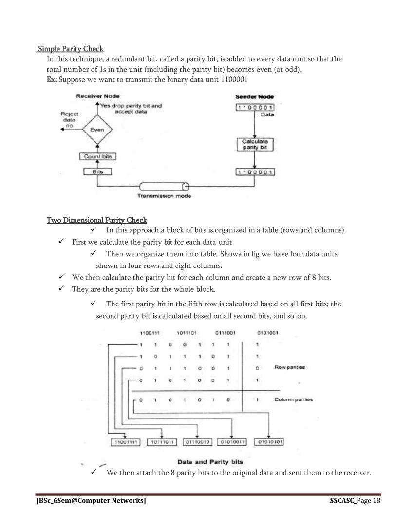
Simple Parity Check
In this technique, a redundant bit, called a parity bit, is added to every data unit so that the
total number of 1s in the unit (including the parity bit) becomes even (or odd).
Ex: Suppose we want to transmit the binary data unit 1100001
Two Dimensional Parity Check
In this approach a block of bits is organized in a table (rows and columns).
First we calculate the parity bit for each data unit.
Then we organize them into table. Shows in fig we have four data units
shown in four rows and eight columns.
We then calculate the parity hit for each column and create a new row of 8 bits.
They are the parity bits for the whole block.
The first parity bit in the fifth row is calculated based on all first bits; the
second parity bit is calculated based on all second bits, and so on.
We then attach the 8 parity bits to the original data and sent them to the receiver.
[BSc_6Sem@Computer Networks] SSCASC_Page 19
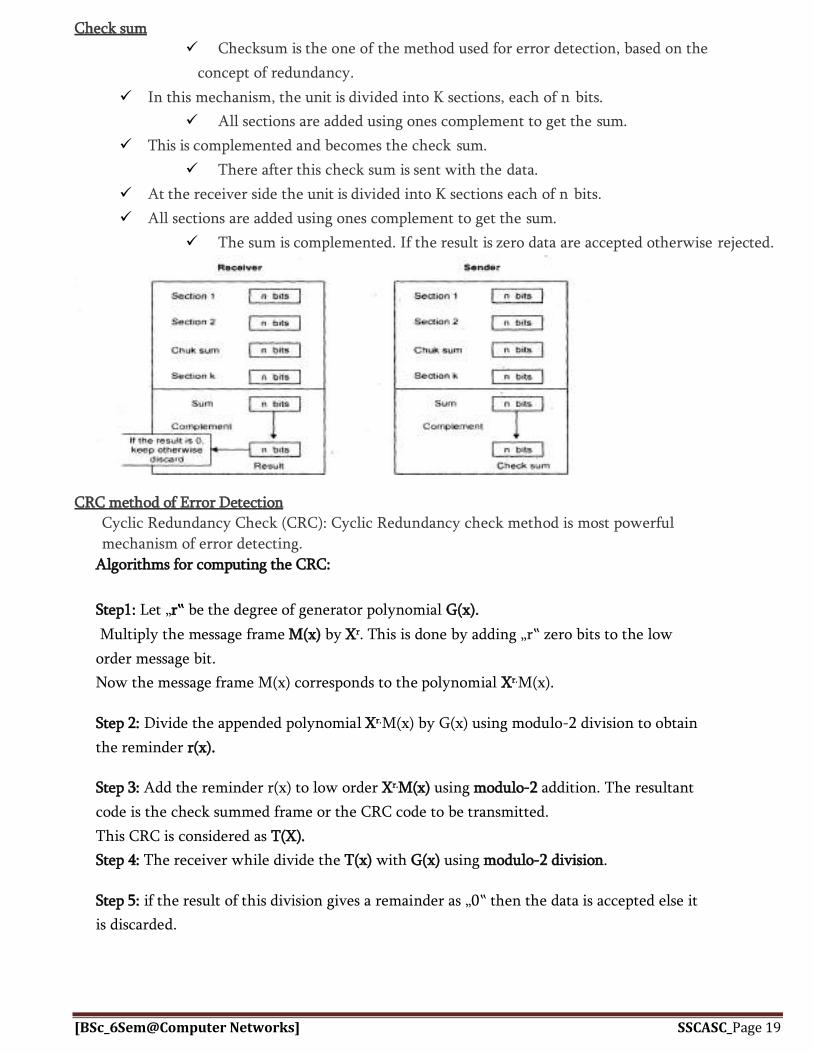
Check sum Checksum is the one of the method used for error detection, based on the
concept of redundancy.
In this mechanism, the unit is divided into K sections, each of n bits.
All sections are added using ones complement to get the sum.
This is complemented and becomes the check sum.
There after this check sum is sent with the data.
At the receiver side the unit is divided into K sections each of n bits.
All sections are added using ones complement to get the sum.
The sum is complemented. If the result is zero data are accepted otherwise rejected.
CRC method of Error Detection
Cyclic Redundancy Check (CRC): Cyclic Redundancy check method is most powerful
mechanism of error detecting.
Algorithms for computing the CRC:
Step1: Let „r‟ be the degree of generator polynomial G(x).
Multiply the message frame M(x) by Xr. This is done by adding „r‟ zero bits to the low
order message bit.
Now the message frame M(x) corresponds to the polynomial Xr.M(x).
Step 2: Divide the appended polynomial Xr.M(x) by G(x) using modulo-2 division to obtain
the reminder r(x).
Step 3: Add the reminder r(x) to low order Xr.M(x) using modulo-2 addition. The resultant
code is the check summed frame or the CRC code to be transmitted.
This CRC is considered as T(X).
Step 4: The receiver while divide the T(x) with G(x) using modulo-2 division.
Step 5: if the result of this division gives a remainder as „0‟ then the data is accepted else it
is discarded.

[BSc_6Sem@Computer Networks] SSCASC_Page 20
Modulo-2 Arithmetic
In modulo-2 arithmetic, we use only 0 and 1. Operations in this arithmetic are very simple. There is no
carry over when we add and no borrow when we subtract one digit from another in a column
Modolo-2 Addition: 0+0=0 0+1=1 1+0=1 1+1=0 Modolo-2 subtraction: 0-0=0 0-1=1 1-0=1 1-1=0
NOTE: Associate bits with coefficients of a polynomial AS FOLLOWS:
1 0 1 1 0 1 1
1x6+0x5+1x4+1x3+0x2+1x+1
= x6+x4+x3+x+1
EXAMPLE :
Sender
– M(x) = 110011 x5+x4+x+1 (6 bits)
– G(x) = 11001 x4+x3+1 (5 bits, n = 4)
4 bits of redundancy
– Form xr M(x) 110011 0000
x9+x8+x5+x4
– Divide xrM(x) by G(x) to find r(x)
11001
11001
100001
10000
11001
1001
r(x) = 1001
Send the block 110011 1001
1100110000

[BSc_6Sem@Computer Networks] SSCASC_Page 21
Receiver 100001
11001 1100111001
11001
11001
11001
00000
No remainder
Accept
HAMMING CODES Hamming codes are the error correction codes that are widely used in reliable
communication. The code is named after its inventor R.Hamming.
The code uses the number of parity bits located at certain position in the code word.
Hamming distance: “The Hamming distance between two words is the number of differences between
corresponding bits.”
Valid Code Word: 10110
Error Code Word: 10100 -----
XOR 00010
Hamming distance d=0+0+0+1+0=1.
The Hamming distance between
1011101 and 1001001 is 2.
Calculating the Hamming Code 1. All the positions in the code word that are powers of 2 (i.e., positions
1, 2, 4, 8….) Are for parity bits P1, P2, P3, P4
2. The rest of the positions (i.e., positions 3, 5, 7, 9….) are for messages bits
M1, M2, M3, and M4.
3. Construct bit location table as shown below.
Bit Designation M7 M6 M5 P4 M3 P2 P1 Bit Location 7 6 5 4 3 2 1 Binary Location Number
111 110 101 100 011 010 001

[BSc_6Sem@Computer Networks] SSCASC_Page 22
Assignment of P1: The binary location number of Parity bit P1 has a 1 for its right most digit. Therefore parity bit P1 checks bit locations 1,3,5,and 7 and assigns value 0
or 1 according to even or odd parity. Assignment of P2:
The binary location number of Parity bit P2 has a 1 for its middle bit digit. Therefore parity bit P2 checks bit locations 2, 3, 6, and 7 and assigns value 0
or 1 according to even or odd parity. Assignment of P4:
The binary location number of Parity bit P4 has a 1 for its left most digit. Therefore parity bit P4 checks bit locations 4, 5, 6,and 7 and assigns value 0
or 1 according to even or odd parity. Correcting Error:
Once hamming code is constructed for the given information bits,
it is sent to the receiver.
At the receiver side, each parity bit, along with its corresponding
group of bits is checked for proper parity.
The correct parity of individual parity check is marked as „0‟ whereas
wrong result is marked as „1‟. This word gives bit locations where error has occurred. If word has all bits „0‟ then there is no error in the hamming code.
Ex: Receiving hamming code is 1100111. Even parity is used. Locate and correct error.
Step1:
Constructing the bit location table:
Bit Designation M7 M6 M5 P4 M3 P2 P1 Bit Location 7 6 5 4 3 2 1 Binary Location Number
111 110 101 100 011 010 001
Received code 1 1 0 0 1 1 1
Step 2: Check for parity bits
P1 checks bit locations 1,3,5 and 7
There are three 1‟s in the group
Therefore parity check even parity is wrong… ............ 1(LSB)
P2 checks bit locations 2, 3, 6, and 7
There are four 1‟s in the group
Therefore parity check even parity is right… ........... 0
P4 checks bit locations 4, 5, 6, and 7
There are two 1‟s in the group Therefore parity check even parity is right… ........... 0
The resultant word is 001.
This says that bit ion the position 1 is in
error. Therefore the data is 1100110.

[BSc_6Sem@Computer Networks] SSCASC_Page 23
PEER TO PEER PROTOCOLS Peer to Peer protocol involves the interaction of two processes or entities. The purpose of a protocol is to provide service to a higher layer by executing layer-n protocol.
Service Models The service provided a protocol is described by a service model. The service model of a given layer specifies the manner in which information is transmitted.
There are 2 broad categories of service models: 1. Connection-oriented
2. Connectionless
Connection-oriented
In this connection is established between two end systems and then the data is
transmitted. This involves 3 phases:
1) Connection establishment: In this phase connection is established
between 2 end systems and during this process dedicated resources will
be allocated for connection establishment and data transfer. 2) Data Transfer: In this phase the actual data is transfer takes place.
Once the data is transmitted it will reach the destination in the proper order as it is
sent from the sender. The acknowledgement for the received data is sent to the receiver.
3) Connection termination: In this phase connection between two end systems is terminated.
The resources that are allocated for communication are released.
Ex: TCP is a connection oriented protocol.
Connectionless In this service connection setup is not done, instead individual blocks of
information are transmitted and delivered based on the destination address
provided. This service doesn‟t provide acknowledgement for transmitted information. If data is lost during transmission, no effort is made to be transmitted.
Ex: IP and UDP are connectionless protocols.
ARQ PROTOCOLs
Error detection is one of the responsibilities of data link layer.
If any error is detected in the transmission, specified frames are
retransmitted .This process is called Automatic Repeat reQuest.
The set of rules that will determine the operations for the sender and
the receiver are named the ARQ protocols.
The 3 commonly used ARQ protocols are: 1. Stop and wait ARQ 2. Go Back N ARQ 3. Selective Repeat ARQ
Stop and wait ARQ Working:
Sender sends one frame and waits for acknowledgement.

[BSc_6Sem@Computer Networks] SSCASC_Page 24
Receiver acknowledges the receiving of the frame. After receiving the acknowledgement, sender sends the next frame. In the case 1.The transmitted frame or returned acknowledgement was lost and 2.The sender‟s timer will timeout.
The sender retransmits the frame.
Use of ACK numbers.
The ACK numbers always announces the sequence number of the next
frame expected by the receiver.
Ex: If frame 0 has arrived, the receiver sends an ACK frame with ACK
1(meaning frame 1 is expected next).
For this purpose, here sender and receiver will have a variable called as Slast and Rnext initially
Slast=0 and Rnext=0
1. Sender A sends a frame 0 and starts timer and store copy
of the frame Here Slast=0 and Rnext=0
2. Receiver site Rnext=0 indicates Receiver is expecting frame with Sequence number
0. It will accept the frame and sends ACK frame with number=1 indicating
receiver is expecting next frame with sequence number=1.
3. Sender receives ACK 1 and transmission is success.
4. Now Slast =1 i.e., sender now sends frame with Seq no =1 but frame 1 lost.
5. Timeout occurs at sender site and assuming frame is lost sender retransmits frame 1.
6. Now Rnext=1 and receiver accepts frame 1 and sends ACK 0 i.e., it is expecting next frame
= frame 0.
7. Now Slast=0, sender sends frame 0.
8. Rnext=0 Receiver will accept frame 0 and sends ACK 1, but ACK 1 lost.
[BSc_6Sem@Computer Networks] SSCASC_Page 25
9. Sender side timeout occurs and assuming frame is lost, it retransmits frame 0.
10. Rnext=1 so receiver will discard the frame 0, which is a duplicate frame and
assuming previous ACK lost. It will resend ACK 1 to sender.
Disadvantages: 1) Stop and wait ARQ works well only on channels that have low propagation delay.
2) In Stop and wait after each frame sent the host must wait for an ACK. During that time it is wasting the bandwidth and becomes Inefficient.
To improve efficiency ACK should be sent after multiple frames
Alternatives: Sliding Window protocol
Go-back-N ARQ
Selective Repeat ARQ
Pipelining: “The process of beginning the next task before that previous task has ended”.
Go-Back-N ARQ and Selective Repeat ARQ implements pipelining.
GO-BACK-N ARQ: o To overcome the inefficient transmission that occurs in stop and wait ARQ,
multiple frames must be in transition to keep the channel busy while waiting for acknowledgement.
o In this protocol we can send several frames before receiving acknowledgements; we keep a copy of these frames until the acknowledgement arrives.
o ACK to one frame validates all frames ahead of this frame called accumulated ACK o If ACK for a frame is not received before timeout, all outstanding frames are
retransmitted – That is why the protocol is called GO-BACK-N ARQ.
SEQUENCE NUMBERS: Frames from a sending station are numbered sequentially. Usually sequence number of each frame is included in the frame header. If the header of the frame allows m-bits for the sequence number, the
sequence numbers range from 0 to 2m-1.
Ex: If m=2, then the only sequence numbers are 0, 1, 2, 3.
SLIDING WINDOW:
Go-Back-N uses the sliding window concept, which defines the range of sequence numbers.
It maintains 2 windows:
1) Send sliding window 2) Receiver sliding window.
Send Sliding Window:
Send window is an imaginary box covering the sequence numbers of
the frames which can be send. The maximum size of the window is 2m-1.

[BSc_6Sem@Computer Networks] SSCASC_Page 26
Sf Sn
The send window divides possible sequence numbers into 4 regions:
Fig: Send sliding window before sliding.
2 3 0 1 2 3 0 1
Fig: Send sliding window after sliding.
Receive window:
The receive window makes that the correct data frames are received
and that correct ACK are sent. The size of the receive window is always 1. The receiver expecting arrival of a specific frame. Any frame arrives out of order will be discarded and needs to be sent.
Rn-next frame expected
Fig: Receive window before sliding
Region 1 Region 2 Region 3 Region 4
Defines frames that
cannot be sent until
window slides
Defines
frames
that can
be sent
Defines frames
waiting for
ACK(0,1)
Defines frames
already ACK(2,3)
2 0 2 1 0 3 1 3
0 1 2 3 0 1 2 3
Frames received
&acknowledged
Frames that cannot be
received until window slides

[BSc_6Sem@Computer Networks] SSCASC_Page 27
Rn-next frame expected
Fig: Receive window after sliding
Fig: Flow diagram of Go-Back-N ARQ
1. Sender window size is 22-1=4-1=3 Sf =0 i.e., sent frame=0. Sn i.e., next frame can be sent
=1,2 Frame 0 sent
2. Receiver side Rn =0 i.e., Receiver expecting
frame=0, So it will accept frame 0 & sends ACK1.
3. ACK1 is lost.
4. Sender side Sf=0,1
Sn =2 Frames 1 sent
5. Rn =1 , So it will accept frame 1 and send
ACK2. ACK2 lost.
6. Frame 2 is sent , Rn=2 accepted & sent ACKs and ACK is lost.
7. Timeout occurs at sender side, and sender did not receive ACK for none of the sent frames.
8. Assuming frames are lost, frame 0 is resent but now, Rn=3.
i.e., receiver is expecting frame 3 but it receives frame 0 which is a duplicate frame so it
discards that frame.
2 1 0 3 2 1 0 3

[BSc_6Sem@Computer Networks] SSCASC_Page 28
SELECTIVE REPEAT ARQ:
In Go-Back-N ARQ we have seen that if one frame is corrupted then all
other N frames were needed to be resent. This drawback is overcome in this
protocol.
Instead of transmitting N frames, here only corrupted frame is
retransmitted. This mechanism is called Selective Repeat ARQ.
Windows:
This protocol uses two windows: Send window and Receive Window. The send window maximum size is 2m-1. Ex: if m=2, 22-1=2.\
Sequence numbers ranges from 0 to 2m-1. Ex: if m=2, 22-
1=3 0,1,2,3,0,1,2,3,0,1,2,3……… Receiver window size is also same as the sender window size 2m-1.
Fig:
Flow diagram of Selective repeat ARQ
1.Sender window size is
2m-1= 22-1=2. Receiver
window size is 2m-1= 22-
1=2.
2. Sender A transmits frame 0. Sf=0 and Sn=1.
3. Receiver side Rn=0,1.
Receiver will accept and sends ACK=1 but ACK 1 is lost.
4.Again sender transmits frame 1 . Receiver
window shows 1,2. So it will accept frame and
sends ACK2 but ACK2 is lost.

[BSc_6Sem@Computer Networks] SSCASC_Page 29
5.Timeout occurs at the sender site and sender didn‟t receive ACK for
frame 0 & frame 1. So sender will retransmit frame 0.
6. Receiver window has 2, 3.
So receiver will correctly discard that frame 0 which is duplicate frame and sends an ACK for
frame 0 and frame 1.
Piggybacking: Piggybacking is a technique used to improve the efficiency of bidirectional
protocols. When a frame is carrying data from A to B, it can also carry control
information about frames from B and vice versa.
Both the sender and receiver maintain control variable S and R. The sender sends Frame0 and ACK0 appended along with it. Similarly the receiver sends Frame0 with ACK1 appended to it. This way both Frame and Acknowledgement will concurrently
increase optimal efficiency of bandwidth utilization.
FRAMING Framing involves identifying the beginning and end of a block of information. Frames can be fixed or variable size. In fixed size framing, there is no need for defining the boundaries of
the frames. (Size itself is a delimiter).
In variable size framing, we have defined the end of the current frame
and beginning of the next frame.
There are two methods available for framing:
Byte stuffing(Character stuffing): Use special characters to identify beginning and end of the frames.
Bit stuffing: Use special bit patterns called flags to identify the beginning and end of the frames.
Byte stuffing: Also referred to as character stuffing. ASCII characters are used as framing delimiters (e.g. DLE STX and DLE ETX) The problem occurs when these character patterns occur within the “transparent” data.

[BSc_6Sem@Computer Networks] SSCASC_Page 30
Solution: sender stuffs an extra DLE into the data stream just before each
occurrence of an “accidental” DLE in the data stream.
The data link layer on the receiving end unstuffs the DLE before giving the data to
the network layer.
A DLE B ETX DLE STX E
DLE STX A DLE B ETX DLE STX E DLE ETX
DLE STX A DLE DLE B ETX DLE DLE STX E DLE ETX
DLE(Data Link Escape)
STX(Start of Text)
ETX(End of Text)
Bit stuffing:
Each frame begins and ends with a special bit pattern called a flag byte [01111110].
{Note this is 7E in hex}
Whenever sender data link layer encounters five consecutive ones in the
data stream, it automatically stuffs a 0 bit into the outgoing stream.
When the receiver sees five consecutive incoming ones followed by
a 0 bit, it automatically dyestuffs the 0 bit before sending the data to
the network layer.
Original data:
0110111111100111110111111111100000
After framing:
01111110 0110111111100111110111111111100000 01111110
After stuffing:
01111110 01101111101100111110011111011111000000 01111110
POINT –TO-POINT PROTOCOL
Point-To-Point protocol is a collection of
protocols(LCP,NCP,PAP, CHAP) Used for point-to-point
communication.
It is a byte-oriented protocol.
Original data
After framing
After Byte stuffing

[BSc_6Sem@Computer Networks] SSCASC_Page 31
Services Provides PPP are:
1. PPP defines the format of the frame that has to be exchanged between two devices.
2. It uses LCP (Link Control Protocol) to establish communication over a PPP link.
3. Provides a method for encapsulating multiple data grams.
i.e., It transfer packets that are produced by different network layer protocols using NCP (Network
Control Protocol).

[BSc_6Sem@Computer Networks] SSCASC_Page 32
The Service provided by PPP can be understood by a simple phase diagram:
Carrier
dropped
Done
Carrier detected
Options
Negotiate
d
Open
Link Dead: In this phase the link is not used. There is no active no carrier in this phase
Lank establishment: If the carrier is detected ppp enter this phase. In this phase with the help of LCP options are negotiated. If the negotiation is success, it enters into authentication phase.
Authenticate: It is an optional phase After the LCP setup the link, the password
authentication protocol (PAP) will authenticate the
sender. If authentication fails, PAP informs the LCP to
terminate the link, if successful control goes to next
phase. Network layer protocol: In this phase Negotiation over network layer protocol
occurs with the help of network control protocol (NCP). Open: In this phase actual transfer of data packets takes place. Terminate:
Once data transfer is completed connection should be terminated
NCP configuration
Terminating
Dead
Link Establishment

[BSc_6Sem@Computer Networks] SSCASC_Page 33
Primary Responses
Secondary
HDLC DEFINES Two TYPES OF DATA TRANSFER MODE:
Normal Response Mode (NRM): Here we have one primary station and multiple secondary stations. The station configuration is unbalanced. The primary station can send commands. And secondary station can only respond. This type can be used for point-to-point and multipoint links.
Commands
(a) point-to-point
Commands Responses
Secondary Secondary
(b) Multi-point
Asynchronous Balanced Mode (ABM) :
• Mainly used in point-to-point links, for communication between
combined stations.
HDLC FRAME FORMAT:
Flag Address Control Information FCS Flag
Flag field: The Flag field of an HDLC frame is and 8-bit sequence with the pattern
01111110, which indicates the beginning and end of the frame.
Address field: It contains the address of the secondary station.
If a primary station is created the frame, it contains a to
address. If a secondary station created the frame, it contains the From address. Control field: It is used for flow and error control. Information field: Contains the actual users data.
FCS: the frame check sequence number is the HDLC error detection field
Secondary Commands Responses Secondary
Primary Responses Commands Primary
Primary
Secondary

[BSc_6Sem@Computer Networks] SSCASC_Page 34
HDLC DEFINES 3 TYPES OF FRAMES:
1) Information frames: They are used to carry user data and control information related to user data. 2) Supervisory frames. They are used for error and flow control purposes and hence contains send and receive
sequence numbers. 3) Un numbered frames: They are reserved for system management.
Control field determines the type of the frame:
I-FRAME:
0 N(S) P/F N(R)
S-FRAME:
1 0 S S P/F N(R)
RAME:
1 1 M M P/F M M M
N(S) =Sender sequence number
N(R) =receiver sequence number
S=supervisory bit If SS=00 Receiver Ready (RR) frame.
SS=01 Receiver Reject (REJ) frame.
SS=10 Receiver Not Ready (RNR)
frame. SS=11
Selective Reject (SREJ) frame. P/F=poll or Final bit If P=1, then frame sent from primary to secondary
F=1, then frame is sent from secondary to
primary.
M=Un numbered frame
[BSc_6Sem@Computer Networks] SSCASC_Page 35
Local Area Networks (LANs)
Local Area Networks are privately-owned networks within a small area, usually a single
building or campus of up to a few kilometers.
LAN characteristics are determined by Topologies MAC (Medium Access Control)
Transmission media
Size of coverage
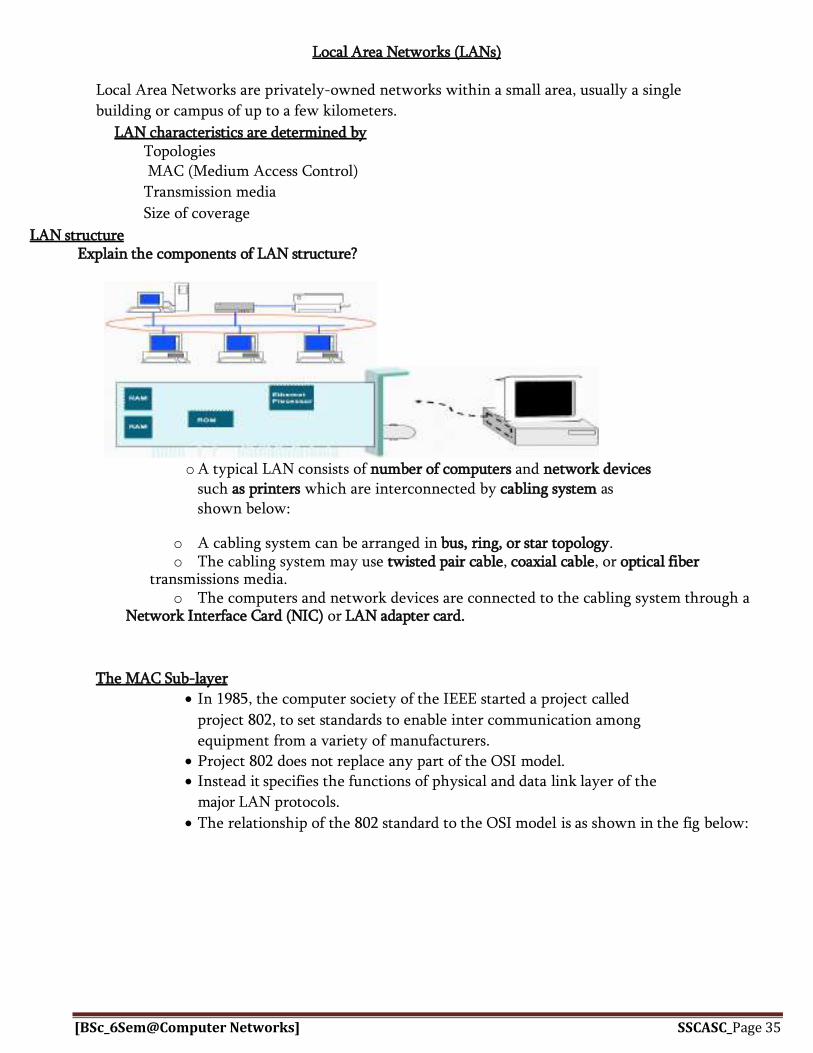
LAN structure Explain the components of LAN structure?
o A typical LAN consists of number of computers and network devices such as printers which are interconnected by cabling system as shown below:
o A cabling system can be arranged in bus, ring, or star topology. o The cabling system may use twisted pair cable, coaxial cable, or optical fiber
transmissions media. o The computers and network devices are connected to the cabling system through a
Network Interface Card (NIC) or LAN adapter card.
The MAC Sub-layer
In 1985, the computer society of the IEEE started a project called
project 802, to set standards to enable inter communication among
equipment from a variety of manufacturers.
Project 802 does not replace any part of the OSI model. Instead it specifies the functions of physical and data link layer of the
major LAN protocols.
The relationship of the 802 standard to the OSI model is as shown in the fig below:

[BSc_6Sem@Computer Networks] SSCASC_Page 36
The IEEE has subdivided the data link layer into two sub layers: LLC (Logical Link Control) and MAC (Medium Access Control)
The MAC sub layer deals with the problem of co-coordinating access
to the shared physical medium.
IEEE has defined several MAC standards namely:
IEEE 802.3 (Ethernet) IEEE
802.4(Token Bus) IEEE
802.5(Token Ring) IEEE
802.11(Wireless LAN)
The LLC sub layer is to provide flow and error control for the upper layer protocols.
Expand MAC and LLC .Name any one protocol used in MAC? MAC: Medium Access Control LLC: Logical Link Control The protocols used in MAC are: CSMA-CD, Token Ring.
IEEE 802.3 (ETHERNET)
It is a LAN protocol that is used in Bus and Star topologies and implements CSMA/CD as the
medium access method.
Ethernet Frame format

[BSc_6Sem@Computer Networks] SSCASC_Page 37
Preamble is followed by start delimiter that consists of the pattern
10101011 (11 indicates start of the frame)
It helps receivers synchronize their clocks to transmitter clock.
Receivers look for change in 10 patterns.
Destination and source addresses are 6 byte long which is used to multicast
the frames to a group of users.
Length filed indicates the number of bytes in information field i.e., the
longest allowable frame is 1518 bytes. Pad field ensures minimum frame size is 64 bytes. FCS field is is 32-bit CRC value used for error checking.
IEEE 802.5 Token Ring
Explain the working and frame format of token ring? Or with a neat frame format explain IEEE
802.5 LAN standard?
IEEE 802.5 LAN standard uses ring topology for their connection and
the information flows from one direction along the ring from source to
the destination and back to the source.
The key notion is that MAC is provided via a small frame called a token
that circulates around the ring.
Possession of the token grants the right to transmit.
IEEE 802.5/Token Ring Frame Formats

[BSc_6Sem@Computer Networks] SSCASC_Page 38
Token frame format is of 3 bytes Starting delimiter
(SD) Ending
delimiter(ED) Access
control (AC)
Data frame format:
Starting delimiter (SD): Starts with J & K symbols represents 0 & 1 respectively for their no transmission which
consumes one byte of memory. Access Control: The second byte in the frame format where
T bit is the token bit T=0 indicates token frame T=1 indicates data frame
& AC consumes one byte of memory in nature.
FC (Frame control): This field indicates whether the frame contains data or MAC information in which it is
identified by FF=01 or 00 respectively.
Source & destination address: These are 6 bytes and will have the address of source & destination in which the frames has
to be transferred.
Information: It is the actual data to be sent.
FCS (Frame Check Sequence): CCITT-32 CRC checksum.
ED field: signals the end of token / data frame.
FS (Frame Status): tells the sending device whether the destination device is on
the ring and, if it is, whether it copied the frame.
IEEE 802.11 Wireless LAN standard What is IEEE 802.11 standard? Or Write a short note on wireless LAN?
802.11 refer to a family of specifications developed by the IEEE for wireless LAN (WLAN)
technology. Wireless technology eliminates wires in the process, simplifies installation and
motion of equipment as well as provides connectivity between computers.
IEEE 802 .11 Terminology
Basic Service Set (BSS): a group of stations that coordinates the access to the medium under a
given instance of the MAC.
Basic service area (BSA): The geographical area covered by the BSS.
Adhoc network: a group of stations within range of each other.
Access point (AP): station integrated into the wireless LAN and the distribution system. ESS (Extended Service Set): An ESS is a set of two or more wireless APs connected to the same wired network that
defines a single logical network segment bounded by a router.

[BSc_6Sem@Computer Networks] SSCASC_Page 39
Page 87
DS (Distribution System): The APs of multiple BSSs are interconnected by the DS. This allows for mobility, because
STAs can move from one BSS to another BSS.
The DS is the logical component used to interconnect BSSs.
The DS provides distribution services to allow for the roaming of STAs between BSSs.
Portal: bridge to other (wired) networks.
Infrastructure network: the combination of BSSs, a DS and portals.
All STAs in a BSS communicate through the AP.
The AP provides connectivity to the wired LAN.
802.11 MAC Frame Format
IEEE 802.11 supports 3 types of frames:
1) Management frames: used for station association and disassociation with the
AP, timing and synchronization and authentication and de authentication.
2) Control frames: Used for handshaking and fro positive
acknowledgements during data exchange.
3) Data frames: Used for transmission of data.
Medium Access Control

[BSc_6Sem@Computer Networks] SSCASC_Page 40
MAC layers in IEEE 802.11 standard
IEEE 802.11 MAC protocol is specified in terms of Co-ordination functions that determine when should be station in a BSS is allowed to
transmit and when it may be able to receive PDUs over the wireless medium.
Distributed co-ordination function (DCF):
It is the basic access method used to support asynchronous data transfer
on a best-effort basis. The DCF is based on CSMA/CA protocol. DCF sits on the top of the physical layer and supports contention free services. Carrier sensing involves monitoring the channel to know whether the
medium is busy or idle.
If the medium is busy it has to wait for some amount of time and
start sensing the medium until medium becomes free.
To avoid the collision, CSMA/CA uses the method that even when the
channel is free it waits for some random amount of time called the
inerframe space (IFS) so that it can avoid the collision.
“A handshake procedure was developed to operate with CSMA/CA when there is a hidden
–station problem.”
IEEE 802.4 Token Bus
IEEE 802.3 has the following Disadvantages 1. Priority for frames is not present:
All traffic (e.g. voice, video, interactive key strokes, background email etc.) is treated the same.
2. Non-deterministic behavior: No absolute bound on delay (waiting time for a station), thus difficult to support
real time applications such as voice and video.
Therefore 802.3 was standardized by IEEE in 1985, and is called Token Bus.
Token Bus is a technique in which the stations on the bus or tree form a
logical ring as shown below:
Token Bus: physically a bus, logically a ring.

[BSc_6Sem@Computer Networks] SSCASC_Page 41
The followings are the basic ideas of Token Bus: 1. A special frame called token is passing around to all the stations.
2. Station that holds the token has the permission to transmit frames.
3. Token holding time limits the number of frames each station can
transmit at one time before releasing to next station.
4. It supports 4 classes of priority.
A station transmits its highest priority frames first, and then it‟s next highest, etc.
until it has transmitted all of its frames or until its time has expired.
5. The physical location on the bus is not important. The protocol follows a
logical ring. Since it is a bus, all stations see all frames.
6. When a new station joins the network, it has to negotiate its order on the passing
order.
7. When a station fails, a timing mechanism is used to remove the station from the
network.
8. A protocol has to follow to regenerate the token if lost; remove
duplicated tokens if generated erroneously.
9.
[BSc_6Sem@Computer Networks] SSCASC_Page 42
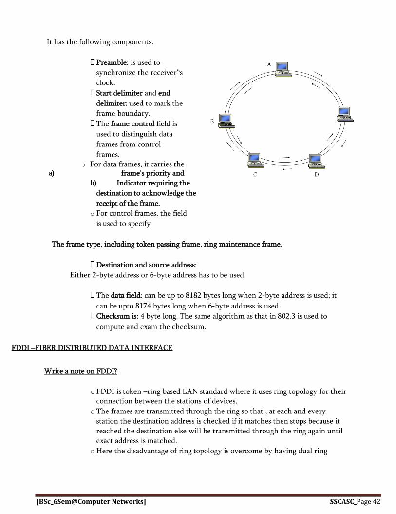
It has the following components.
Preamble: is used to
synchronize the receiver‟s
clock.
Start delimiter and end
delimiter: used to mark the
frame boundary.
The frame control field is
used to distinguish data
frames from control
frames. o For data frames, it carries the
a) frame's priority and b) Indicator requiring the
destination to acknowledge the
receipt of the frame.
o For control frames, the field
is used to specify
The frame type, including token passing frame, ring maintenance frame,
Destination and source address:
Either 2-byte address or 6-byte address has to be used.
The data field: can be up to 8182 bytes long when 2-byte address is used; it
can be upto 8174 bytes long when 6-byte address is used.
Checksum is: 4 byte long. The same algorithm as that in 802.3 is used to
compute and exam the checksum.
FDDI –FIBER DISTRIBUTED DATA INTERFACE
Write a note on FDDI?
o FDDI is token –ring based LAN standard where it uses ring topology for their
connection between the stations of devices.
o The frames are transmitted through the ring so that , at each and every station the destination address is checked if it matches then stops because it reached the destination else will be transmitted through the ring again until exact address is matched.
o Here the disadvantage of ring topology is overcome by having dual ring

[BSc_6Sem@Computer Networks] SSCASC_Page 43
arrangement as shown in figure.
o If there is any break in the ring then it takes opposite direction of flow from the last station before the break.

[BSc_6Sem@Computer Networks] SSCASC_Page 4444
FDDI frame structure:
Preamble: signals the start of the frame.
SD: start of the frame delimiter signals the start of the frame‟s contents.
FC: signals the type of the frame.
Source & destination address:
These are 6 bytes and will have the address of source & destination in which the frames has to be
transferred.
Information: It is the actual data to be sent.
FCS (Frame Check Sequence): CCITT-32 CRC checksum.
ED field: signals the end of token / data frame.
FS (Frame Status): tells the sending device whether the destination device is on the
ring and, if it is, whether it copied the frame.
[BSc_6Sem@Computer Networks] SSCASC_Page 4545
Chapter 5. Network layer-Internetworks
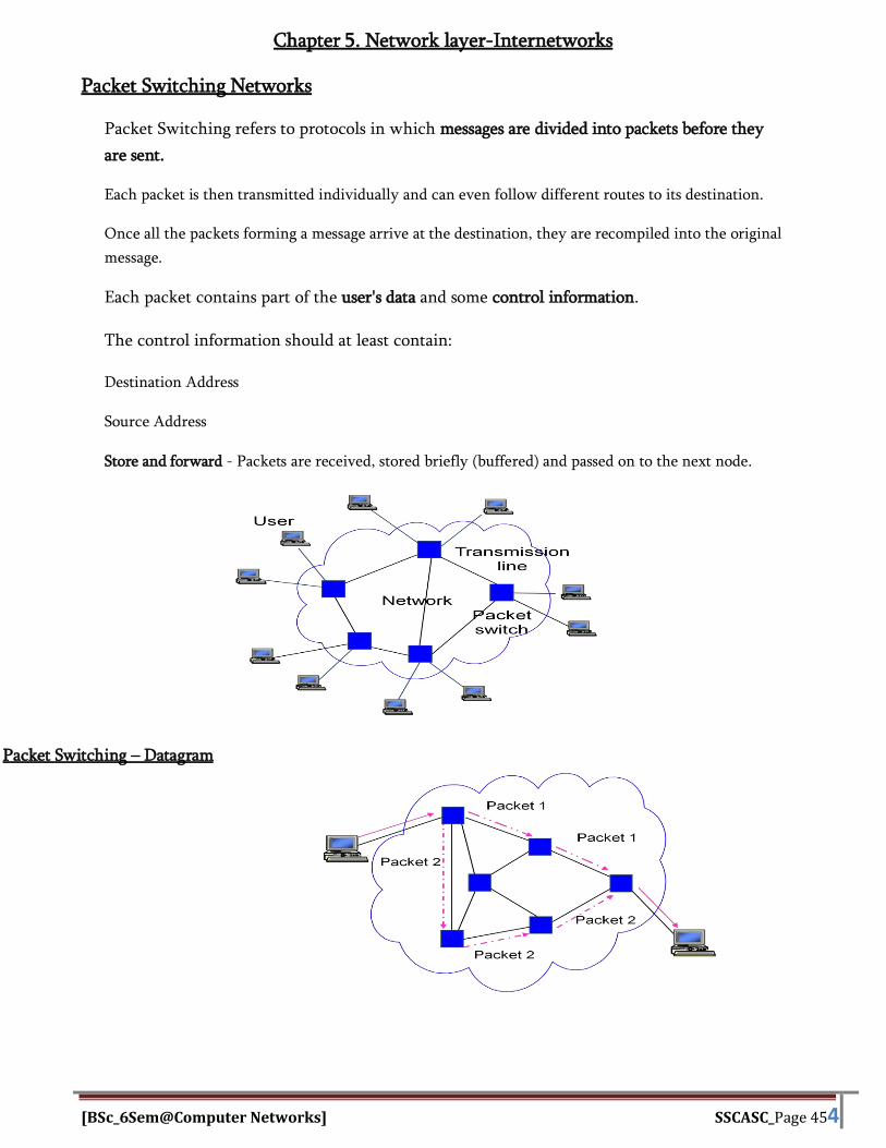
Packet Switching Networks
Packet Switching refers to protocols in which messages are divided into packets before they
are sent.
Each packet is then transmitted individually and can even follow different routes to its destination.
Once all the packets forming a message arrive at the destination, they are recompiled into the original
message.
Each packet contains part of the user's data and some control information.
The control information should at least contain:
Destination Address
Source Address
Store and forward - Packets are received, stored briefly (buffered) and passed on to the next node.
Packet Switching – Datagram
[BSc_6Sem@Computer Networks] SSCASC_Page 4646
1. This method is also referred as connection less packet switching.
2. Packets in this approach are called datagram.
3. Each packet is treated independently of all others.
4. To do this each packet must be individually addressed to determine where
its source and destination are.
5. Each node chooses the path for each packet, taking into account the
information from its neighboring node regarding traffic, line failures and so
on.
6. The packets with same destination address may or may not follow the
same path, and they may arrive out of sequence at the destination.
7. Packets may also lost or dropped because of lack of resources.
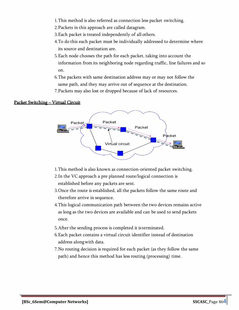
Packet Switching – Virtual Circuit
1. This method is also known as connection-oriented packet switching.
2. In the VC approach a pre planned route/logical connection is
established before any packets are sent.
3. Once the route is established, all the packets follow the same route and
therefore arrive in sequence.
4. This logical communication path between the two devices remains active
as long as the two devices are available and can be used to send packets
once.
5. After the sending process is completed it is terminated.
6. Each packet contains a virtual circuit identifier instead of destination
address along with data.
7. No routing decision is required for each packet (as they follow the same
path) and hence this method has less routing (processing) time.

[BSc_6Sem@Computer Networks] SSCASC_Page 4747
Routing Algorithms
The routing algorithm is network layer software which decides
routes and the data structures they use for an incoming packet to be
transmitted further.
The routing may be within a network or between networks depending
upon the source and destination.
Routing Algorithm Requirements
Desirable features of routing algorithms i) Correctness
ii) Responsiveness to changes iii) Optimality iv) Robustness v) Simplicity
Routing algorithms are of two types: 1) Non adaptive 2) Adaptive
Non adaptive or static routing algorithms When the information about the network topology and traffic is known, non adaptive algorithms are
used.
When the topology is static and traffic is not changing, the following algorithms are used. a) Shortest path routing
b) Flooding c) Flow based routing
Two commonly implemented shortest path routing algorithms are: 1) Dijikstra‟s algorithm 2) Bellman Ford algorithm
DIJIKSTRA‟S ALGORITHM
The principle of dijikstra‟s algorithm is “To progressively identify the shortest path from the
source node to all other nodes by developing the path in order of increasing path length”
Working: Step 1:Each node is labeled with its distance from the source node along the best known path. Step 2:Initially assume that no paths are found and all nodes can be labeled with infinity. Step
3:As the algorithm proceeds and the paths are found , the labels may change, reflecting better
paths.
Step 4:The labels are initially tentative. When it is known that label represents the shortest possible
path from the source to that node, it is made permanent and no changes are made thereafter.

[BSc_6Sem@Computer Networks] SSCASC_Page 4848
Example: Consider the following undirected graph
Step 1: Since A is the source, start making node A as permanent, indicated by a filled circle. Then examine the adjacent nodes to A. The adjacent nodes are B, C and E. Node C is with the smallest label and makes it permanent as in the figure.
Step 2: Now start at C and examine all the nodes adjacent to it. The adjacent nodes are E
and D. We have E(2,A) the total distance from A to E
through C is AC+CE i.e., 2
For node D, from A through is AC+CD i.e., 5.
So the new label on D is D (5, C) as in the figure.
Step 3:
Mark E as permanent because E has smallest label as D.
Starting from E, the adjacent nodes to E are B and D.
The distance from A to D through B and E is AE+EB+BD i.e., 6
which is not the shortest.
But the route from A to D through C and E are AC+CE+ED i. e., 3 which
is shorter than other route.
Therefore finally the shortest path from A to D
using dijikstra‟s algorithm is

[BSc_6Sem@Computer Networks] SSCASC_Page 4949
AC CE ED which is 3. Hence ACED is the shortest path.

[BSc_6Sem@Computer Networks] SSCASC_Page 5050
BELLMAN FORD ALGORITHM
The principle of d Bellman Ford algorithm is “Each neighbor of source node knows the
shortest path to the destination node.
The source node can then determine the shortest path to destination node by calculating distance to
destination node through each of its neighbors and then picking up the minimum.
Working:
1) Initially mark all the nodes except source as ∞. 2) And the distance to destination Dd=0.
3) Find the minimum distance to the destination through
neighbors: For each i≠d.
Di-minj(Cij+Dj), for all j≠i.
4) Repeat step 2 until destination is reached..
Iteration Node 1 Node 2 Node 3 Node 4 Node 5
Initial (-1, ) (-1, ) (-1, ) (-1, ) (-1, )
1 (-1, ) (-1, ) (6, 1) (-1, ) (6,2)
2 (3,3) (5,6) (6, 1) (3,3) (6,2)
3 (3,3) (4,4) (6, 1) (3,3) (6,2)

[BSc_6Sem@Computer Networks] SSCASC_Page 5151
FLOODI NG ALGORITHM
“It is an approach in which, every incoming packet at each node is sent out on
every outgoing line except the one which it arrived”.
A2
Advantages:
1. Increased reliability, since the message will be sent at least once to every host.
2. Widely used in military applications, wireless networks and
distributed database applications.
Dis Advantages: 1. It is very useful in terms of networks total bandwidth.
While a message may Only have one destination it has to be sent to every host.
2. Messages can also become duplicated in the network further increasing the load.
3. Two approaches are implemented to prevent duplication of packets.
FLOW BASED ROUTING:
1. This algorithm considers both topology and load(traffic).
2. This technology requires certain information in advance.
a) Subnet topology
b) Traffic matrix (Fij)
c) Capacity matrix (Cij) [capacity of each line in
bps] finally a routing algorithm must be chosen.
Working principle: Step1: The idea behind the analysis is that for a given line, if the capacity and average flow are known,
it is possible to compute the mean packet delay on that line from queuing theory.
Step 2: From the mean delays on all the lines, it is straightforward to calculate a flow-weighted
average to get the mean packet delay for the whole subnet.
Step 3: The routing problem then reduces to finding the routing algorithm that produces the
minimum average delay for the subnet.
Mean delay can be calculated from T(sec)=1/µ (C-λ)
Where C(in bps)=Line capacity, λ=maen flow (in pac/sec),1/µ=mean packet size
A1
R Incoming line
A3

[BSc_6Sem@Computer Networks] SSCASC_Page 8
ADAPTIVE ALGORITHM
Here the routing strategies react to the changing conditions within the network.
The following algorithms are used:
a) Distance vector routing
b) Link state routing
c) Hierarchical routing
Distance vector routing
Each node constructs a one-dimensional array containing the "distances"(costs) to all other nodes and
distributes that vector to its immediate neighbors.
1. The starting assumption for distance-vector routing is that each node
knows the cost of the link to each of its directly connected neighbors.
2. A link that is down is assigned an infinite
cost. 3.
Inform
ation
Stored at
Node
Distance to Reach Node
A B C D E F G
A 0 1 1 ? 1 1 ?
B 1 0 1 ? ? ? ?
C 1 1 0 1 ? ? ?
D ? ? 1 0 ? ? 1
E 1 ? ? ? 0 ? ?
F 1 ? ? ? ? 0 1
G ? ? ? 1 ? 1 0
Initial distances stored at each node (global view).

[BSc_6Sem@Computer Networks] SSCASC_Page 8
Final distances stored at each node (global view).
We can represent each node's knowledge about the distances to all other nodes as a table like the one
given in Table 1.
Note that each node only knows the information in one row of the table.
1. Every node sends a message to its directly connected neighbors containing its
personal list of distance. (For example, A sends its information to its
neighbors B, C, E, and F.)
2. If any of the recipients of the information from A find that A is advertising a
path shorter than the one they currently know about, they update their list to
give the new path length and note that they should send packets for that
destination through A. ( node B learns from A that node E can be reached at a
cost of 1; B also knows it can reach A at a cost of 1, so it adds these to get the
cost of reaching E by means of A. B records that it can reach E at a cost of 2 by
going through A.)
3. After every node has exchanged a few updates with its directly connected
neighbors, all nodes will know the least-cost path to all the other nodes.
4. In addition to updating their list of distances when they receive updates, the
nodes need to keep track of which node told them about the path that they
used to calculate the cost, so that they can create their forwarding table. ( for
example, B knows that it was A who said " I can reach E in one hop" and so B
puts an entry in its table that says " To reach E, use the link to A.)
Informa tion
Stored
at Nod e
Distance to Reach Node
A B C D E F G
A 0 1 1 2 1 1 2
B 1 0 1 2 2 2 3
C 1 1 0 1 2 2 2
D 2 2 1 0 3 2 1
E 1 2 2 3 0 2 3
F 1 2 2 2 2 0 1
G 2 3 2 1 3 1 0

[BSc_6Sem@Computer Networks] SSCASC_Page 8
LINK STATE ROUTING
Link state routing technique consists of 5 steps:
1.) Discover your neighbors and learn their addresses. Send “Hello” packet on each point-to-point line. Destination node replies with its address.
2.) Measure the cost (delay) to each neighbor. Send an “ECHO” packet over the line.
Destination is required to respond to “ECHO” packet immediately.
Measure the time required for this operation.
3.) Construct a packet containing all this information Each router creates a link state packet (LSP) which contains names (e.g. network
addresses) and cost to each of its neighbours
The LSP is transmitted to all other routers, who each update their own records When a router receives LSPs from all routers, it can use (collectively) that information to
make topology-level decisions.
4.) Send this packet to all other routers. Use selective flooding
Sequence numbers prevent duplicate packets from being propagated
Lower sequence numbers are rejected as obsolete
5.) Compute the shortest path to every other router. Dijkstra‟s Shortest Path algorithm is used to determine the shortest path to each destination.

BSc_6Sem@Computer Networks] SSCASC_Page 3
HIERARCHICAL ROUTING
1. As the network grows the number of routers in the network increases.
2. The size of routing tables becomes enormous and makes routing impossible.
3. We use hierarchical routing to overcome this problem.
4. In the hierarchical routing, routers are classified in groups as regions. Each
router has only the information about the routers in its own region and has
no information about routers in other regions.
5. If A wants to send packets to any router in region 2 (D, E, F, or G), it sends
them to B and so on.
6. As you can see, in this type of routing, the tables can be summarized,
so the network efficiency improves.
7. The example shows two-level hierarchical routing.
IPv4 (Internet Protocol Version 4) IPv4 is a connectionless protocol for a packet switching network that uses the Datagram
approach. IPv4 is defined and specified in IETF publication RFC 791.
Datagram is handled independently and each datagram can follow a different route to the
destination.
Datagram Frame format
Packets in the IPv4 layer called Datagram. A Datagram is a variable length packet
consisting of two parts header and Data; header is 20 to 60 bytes in length and contains
information for routing.
VERSION: Version of the IP protocol (4 bits), which is 4 for IPv4
HLEN: IP header length (4 bits), which is the number of 32 bit words in the header. The minimum value
for this field is 5 and the maximum is 15.
Destination Line Weight
A N/A N/A
B B 1
C C 1
Region 2 B 2
Region 3 C 4
Region 4 C 3
Region 5 C 2

BSc_6Sem@Computer Networks] SSCASC_Page 4
Type of service: Low Delay, High Throughput, Reliability (8 bits)
Total Length: Length of header + Data (16 bits), which has a minimum value 20 bytes and the maximum
is 65,535 bytes.
Identification: Unique Packet Id for identifying the group of fragments of a single IP datagram (16 bits)
Flags: 3 flags of 1 bit each: reserved bit (must be zero), do not fragment flag, more fragments flag (same
order)
Fragment Offset: Represents the number of Data Bytes ahead of the particular fragment in the particular
Datagram. Specified in terms of number of 8 bytes, which has the maximum value of 65,528 bytes.
Time to live: Datagram’s lifetime (8 bits), It prevents the datagram to loop through the network by
restricting the number of Hops taken by a Packet before delivering to the Destination.
Protocol: Name of the protocol to which the data is to be passed (8 bits)
Header Checksum: 16 bits header checksum for checking errors in the datagram header
Source IP address: 32 bits IP address of the sender
Destination IP address: 32 bits IP address of the receiver
Option: Optional information such as source route, record route. Used by the Network administrator to
check whether a path is working or not.

BSc_6Sem@Computer Networks] SSCASC_Page 5
Internet Protocol version 6 (IPv6) Header
Prerequisite: Introduction to Internet Protocol version 6
IP version 6 is the new version of Internet Protocol, which is way better than IP version 4 in terms of
complexity and efficiency. Let’s look at the header of IP version 6 and understand how it is different from
IPv4 header.
IP version 6 Header Format:
Version (4-bits) : Indicates version of Internet Protocol which contains bit sequence 0110.
Traffic Class (8-bits) : The Traffic Class field indicates class or priority of IPv6 packet which is similar
to Service Field in IPv4 packet. It helps routers to handle the traffic based on priority of the packet. If
congestion occurs on router then packets with least priority will be discarded.
As of now only 4-bits are being used (and remaining bits are under research), in which 0 to 7 are
assigned to Congestion controlled traffic and 8 to 15 are assigned to Uncontrolled traffic.
Priority assignment of Congestion controlled traffic:
Uncontrolled data traffic is mainly used for Audio/Video data. So we give higher priority to Uncontrolled
data traffic.
Source node is allowed to set the priorities but on the way routers can change it. Therefore, destination
should not expect same priority which was set by source node.
Flow Label (20-bits) : Flow Label field is used by source to label the packets belonging to the same flow in
order to request special handling by intermediate IPv6 routers, such as non-default quality of service or
real time service. In order to distinguish the flow, intermediate router can use source address, destination
address and flow label of the packets..
Payload Length (16-bits) : It is a 16-bit (unsigned integer) field, indicates total size of the payload which
tells routers about amount of information a particular packet contains in its payload. In case length of
payload is greater than 65,535 bytes (payload up to 65,535 bytes can be indicated with 16-bits),
Next Header (8-bits) : Next Header indicates type of extension header(if present) immediately following
the IPv6 header. Whereas In some cases it indicates the protocols contained within upper-layer packet,
such as TCP, UDP.

BSc_6Sem@Computer Networks] SSCASC_Page 6
Hop Limit (8-bits) : Hop Limit field is same as TTL in IPv4 packets. It indicates the maximum number of
intermediate nodes IPv6 packet is allowed to travel. Its value gets decremented by one, by each node that
forwards the packet and packet is discarded if value decrements to 0.
Source Address (128-bits) : Source Address is 128-bit IPv6 address of the original source of the packet.
Destination Address (128-bits) : Destination Address field indicates the IPv6 address of the final
destination(in most cases). All the intermediate nodes can use this information in order to correctly route
the packet.
Extension Headers: In order to rectify the limitations of IPv4 Option Field, Extension Headers are
introduced in IPversion 6. The extension header mechanism is very important part of the IPv6
architecture. Next Header field of IPv6 fixed header points to the first Extension Header and this first
extension header points to the second extension header and so on.
Quality of service
Quality of service (Q o S) is the description or measurement of the overall performance of a service, such
as a telephony or computer network or a cloud computing service, particularly the performance seen by
the users of the network. To quantitatively measure quality of service, several related aspects of the
network service are often considered, such as packet loss, bit rate, throughput, transmission
delay, availability, jitter, etc.
In the field of computer networking and other packet-switched telecommunication networks, quality of
service refers to traffic prioritization and resource reservation control mechanisms rather than the
achieved service quality. Quality of service is the ability to provide different priority to different
applications, users, or data flows, or to guarantee a certain level of performance to a data flow.

BSc_6Sem@Computer Networks] SSCASC_Page 7
Quality of service is particularly important for the transport of traffic with special requirements. In
particular, developers have introduced Voice over IP technology to allow computer networks to become
as useful as telephone networks for audio conversations, as well as supporting new applications with even
stricter network performance requirements.
Chapter 6.Transport Layer MULTIPLEXING
Multiplexing is the set of techniques that allows simultaneous transmission of multiple signals
across a single data link
Need for multiplexing
As data and telecommunication usage increases, the traffic increases.
To accommodate this increase, individual lines are added each time a
new channel is needed or higher capacity links are installed and are used
to carry multiple signals.
If the transmission capacity of a link is greater than the transmission needs of the
devices connected to it, the excess capacity is wasted. Hence, the transmission
capacity of a link can be shared similar to a large water pipe carrying water to
several separate houses at a time.
A technique called multiplexing is designed to reduce the number of
links by combing multiple communication paths over a single carrier.
The aim is to share an expensive resource. For example several
phone calls may be transferred using one wire.
A device that perform the multiplexing is called a multiplexing (MUX),
and a device that perform the reverse process is called a demultiplex
(DEMUX).
The four device on the left direct their transmission stream to a multiplexer (mux) which combines
them into a single stream (many to one) thus sharing the capacity of link
At the receiving end, demultiplexer (DEMUX) separates the signals stream back into its
component transmission (one to many) and directs them to their intended device
Frequency Division Multiplexing • In analog transmission, signals are commonly multiplexed using
frequency division multiplexing
• In FDM the available bandwidth of a communication channel is shared
among multiple user
• The carrier bandwidth is divided into sub channels of different frequency
width and each sub channel is allocated to the user
• Signals generated by each user are modulated into different carrier
frequencies and are then combined into a single composite signals can be
transported by the link
• Channel are separated strips of unused bandwidth called guard bands to
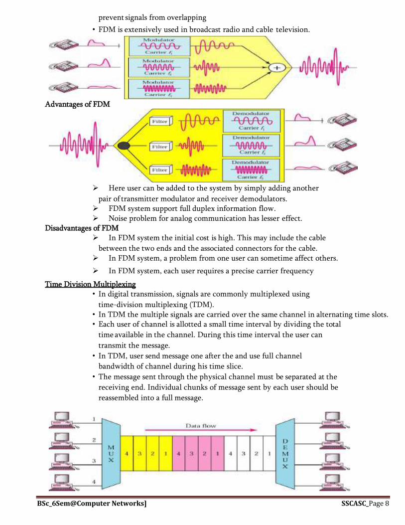
BSc_6Sem@Computer Networks] SSCASC_Page 8
prevent signals from overlapping
• FDM is extensively used in broadcast radio and cable television.
Advantages of FDM
Here user can be added to the system by simply adding another
pair of transmitter modulator and receiver demodulators. FDM system support full duplex information flow. Noise problem for analog communication has lesser effect.
Disadvantages of FDM In FDM system the initial cost is high. This may include the cable
between the two ends and the associated connectors for the cable. In FDM system, a problem from one user can sometime affect others.
In FDM system, each user requires a precise carrier frequency
Time Division Multiplexing • In digital transmission, signals are commonly multiplexed using
time-division multiplexing (TDM). • In TDM the multiple signals are carried over the same channel in alternating time slots. • Each user of channel is allotted a small time interval by dividing the total
time available in the channel. During this time interval the user can
transmit the message.
• In TDM, user send message one after the and use full channel
bandwidth of channel during his time slice.
• The message sent through the physical channel must be separated at the
receiving end. Individual chunks of message sent by each user should be
reassembled into a full message.

BSc_6Sem@Computer Networks] SSCASC_Page 9
Advantages of TDM It uses a single link. It does not require carrier matching at both end of the links. Use of capacity is high. There is no need to include identification of the traffic stream on each packet.
Disadvantages of TDM Initial cost is high. Technical complexity is more TDM can only be used for digital data multiplexing.
Wavelength Division Multiplexing (WDM) WDM is a technology that closely resembles FDM, but here several light
signals of different frequencies are combined into one single light signal at
the multiplexer and sent at the same time through the optical fiber. One of the applications of WDM is SONET.
Multiplexing and Demultiplexing in Transport Layer
Multiplexing and Demultiplexing services are provided in almost every protocol
architecture ever designed. UDP and TCP perform the demultiplexing and multiplexing
jobs by including two special fields in the segment headers: the source port number field
and the destination port number field.
Multiplexing –
Gathering data from multiple application processes of sender, enveloping that data with header and
sending them as a whole to the intended receiver is called as multiplexing.
Demultiplexing –
Delivering received segments at receiver side to the correct app layer processes is called as
demultiplexing.
Figure – Abstract view of multiplexing and demultiplexing
Multiplexing and demultiplexing are the services facilitated by the transport layer of OSI model.

BSc_6Sem@Computer Networks] SSCASC_Page 10
Figure – Transport layer- junction for multiplexing and demultiplexing
There are two types of multiplexing and Demultiplexing :
1. Connectionless Multiplexing and Demultiplexing
2. Connection-Oriented Multiplexing and Demultiplexing
How Multiplexing and Demultiplexing is done –
For sending data from an application at sender side to an application at the destination side, sender must
know the IP address of destination and port number of the application (at the destination side) to which
he want to transfer the data. Block diagram is shown below :
Figure – Transfer of packet between applications of sender and receiver
Let us consider two messaging apps that are widely used now a days viz. Hike and whatsapp.
Suppose A is the sender and B is the receiver. Both sender and receiver have these applications installed
in their system (say smartphone). Suppose A want to send messages to B in whatsapp and hike both. In
order to do so, A must mention the IP address of B and destination port number of the whatsapp while
sending the message through whatsapp application. Similarly, for the later case, A must mention the IP
address of B and destination port number of the hike while sending the message
SONET/SDH (Synchronous Optical Networking / Synchronous Digital Hierarchy) o SONET is a synchronous TDM system controlled by a master clock.
Synchronous: A single clock is used to handle the timing of transmission and equipment across the
entire network.
o It was intended to provide a specification for taking advantage of high speed digital transmission capability of optical fiber.

BSc_6Sem@Computer Networks] SSCASC_Page 11
o SONET uses 51.84 Mbps electrical signal known as the synchronous transport signal level- 1(STS-1).
o Each STS level (STS-1 to STS-192) supports a certain data rate, specified in megabits per second.
o The physical links defined to carry each level of STS are called optical carriers (OCs). o Lower rate STS s can be multiplexed to make them compatible with higher rate systems.
o Ex: Three STS-1 s can be combined into one STS-3 as shown in fig.
CONGESTION
“Congestion is a situation in a network that may occur if load on the network (the no.
of packets sent to the network) is greater than the capacity of the network (no. of
packets a network can handle).
Factors causing congestion:
1. The input traffic rate exceeds the capacity of the output lines.
2. The routers are too slow to perform book keeping tasks(queuing buffers , updating
tables
3. The router‟s buffer is too limited.
CONGESTION CONTROL
In general congestion control mechanisms are divided into 2 broad categories:
1. Open-loop congestion control(prevention)
2. Closed-loop congestion control(removal)
Open loop policies
Open loop policies are applied to prevent congestion before it happens.
Open loop control relies on 3 mechanisms: Admission control, policing, and traffic shaping.
1) Admission control:
Admission control is a network function that computes the resources(bandwidth and buffers)
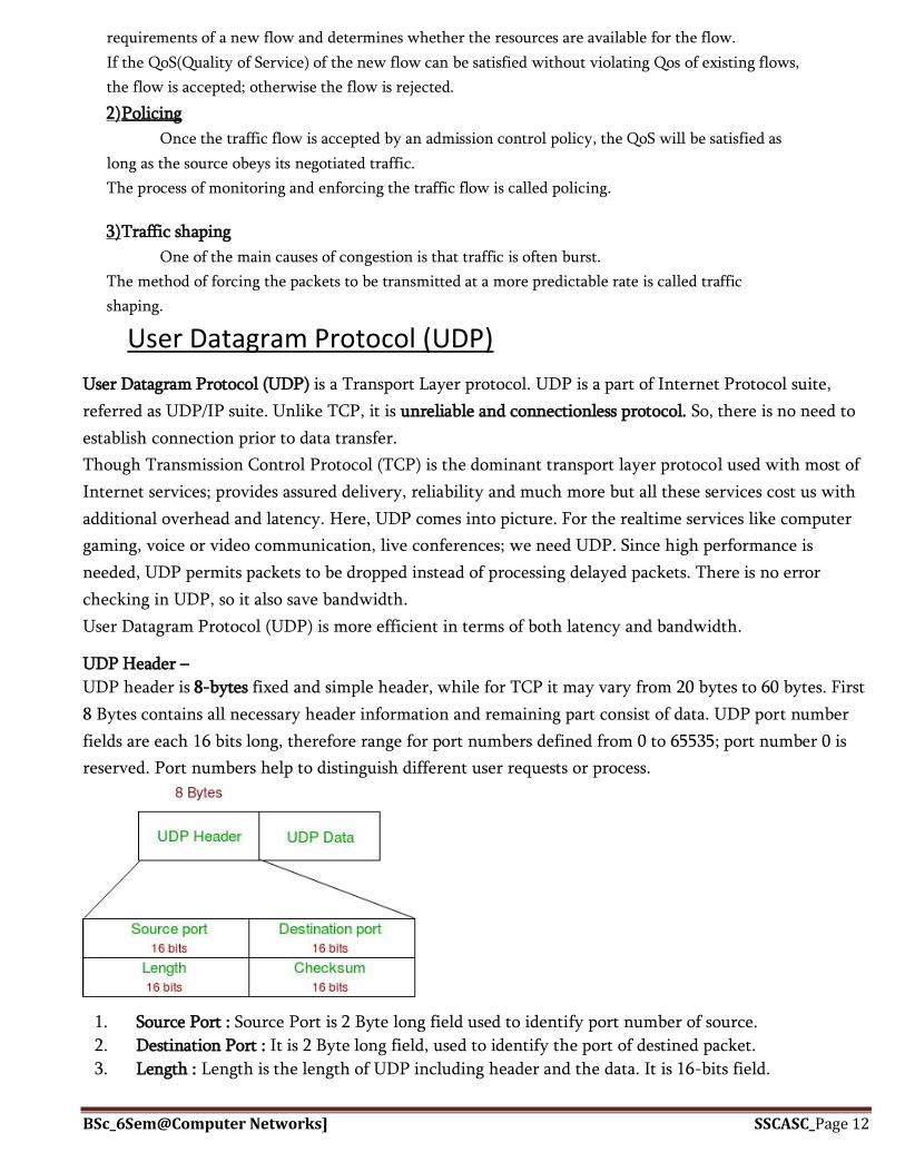
BSc_6Sem@Computer Networks] SSCASC_Page 12
requirements of a new flow and determines whether the resources are available for the flow.
If the QoS(Quality of Service) of the new flow can be satisfied without violating Qos of existing flows,
the flow is accepted; otherwise the flow is rejected.
2) Policing
Once the traffic flow is accepted by an admission control policy, the QoS will be satisfied as
long as the source obeys its negotiated traffic.
The process of monitoring and enforcing the traffic flow is called policing.
3) Traffic shaping
One of the main causes of congestion is that traffic is often burst.
The method of forcing the packets to be transmitted at a more predictable rate is called traffic
shaping.
User Datagram Protocol (UDP)
User Datagram Protocol (UDP) is a Transport Layer protocol. UDP is a part of Internet Protocol suite,
referred as UDP/IP suite. Unlike TCP, it is unreliable and connectionless protocol. So, there is no need to
establish connection prior to data transfer.
Though Transmission Control Protocol (TCP) is the dominant transport layer protocol used with most of
Internet services; provides assured delivery, reliability and much more but all these services cost us with
additional overhead and latency. Here, UDP comes into picture. For the realtime services like computer
gaming, voice or video communication, live conferences; we need UDP. Since high performance is
needed, UDP permits packets to be dropped instead of processing delayed packets. There is no error
checking in UDP, so it also save bandwidth.
User Datagram Protocol (UDP) is more efficient in terms of both latency and bandwidth.
UDP Header –
UDP header is 8-bytes fixed and simple header, while for TCP it may vary from 20 bytes to 60 bytes. First
8 Bytes contains all necessary header information and remaining part consist of data. UDP port number
fields are each 16 bits long, therefore range for port numbers defined from 0 to 65535; port number 0 is
reserved. Port numbers help to distinguish different user requests or process.
1. Source Port : Source Port is 2 Byte long field used to identify port number of source.
2. Destination Port : It is 2 Byte long field, used to identify the port of destined packet.
3. Length : Length is the length of UDP including header and the data. It is 16-bits field.

BSc_6Sem@Computer Networks] SSCASC_Page 13
4. Checksum : Checksum is 2 Bytes long field. It is the 16-bit one’s complement of the one’s
complement sum of the UDP header, pseudo header of information from the IP header and the data,
padded with zero octets at the end (if necessary) to make a multiple of two octets.
Notes – Unlike TCP, Checksum calculation is not mandatory in UDP. No Error control or flow control is
provided by UDP. Hence UDP depends on IP and ICMP for error reporting.
Applications of UDP:
Used for simple request response communication when size of data is less and hence there is lesser
concern about flow and error control.
It is suitable protocol for multicasting as UDP supports packet switching.
UDP is used for some routing update protocols like RIP(Routing Information Protocol).
Normally used for real time applications which can not tolerate uneven delays between sections of
a received message.
Following implementations uses UDP as a transport layer protocol:
NTP (Network Time Protocol)
DNS (Domain Name Service)
BOOTP, DHCP.
NNP (Network News Protocol)
Quote of the day protocol
TFTP, RTSP, RIP, OSPF.
Application layer can do some of the tasks through UDP-
Trace Route
Record Route
Time stamp
UDP takes datagram from Network Layer, attach its header and send it to the user. So, it works
fast.
Actually UDP is null protocol if you remove checksum field.

BSc_6Sem@Computer Networks] SSCASC_Page 14
Chapter 7.Modern Wireless Communications Systems
What is wireless generation?
The mobile wireless Generation (G) generally refers to a change in the nature of the system, speed,
technology, frequency, data capacity, latency etc. Each generation have some standards, different
capacities, new techniques and new features
Generations of Wireless Network: 1G, 2G, 3G & 4G -
1G, which stands for "first generation," refers to the first generation of wireless telecommunication
Technology, more popularly known as cellphones. A set of wireless standards developed in the 1980's,
1G technology replaced 0G technology .1G wireless networks used analog radio signals.
Through 1G, a voice call gets modulated to a higher frequency of about 150MHz and up as it is
Transmitted between radio towers. This is done using a technique called
Frequency-Division Multiple Access (FDMA).
Different 1G standard were used in various countries. Advanced Mobile Phone System
(AMPS) was a 1G standard used in the United States. Nordic Mobile Telephone (NMT)
was a 1G standard used in Nordic countries (Denmark, Finland, Iceland, Norway and Sweden),
as well as in its neighboring countries Switzerland and Netherlands, Eastern Europe,
and Russia. Italy used a telecommunications system called RTMI.In the United Kingdom,
Total Access Communication System (TACS) was used. France used Radiocom 2000.
Second Generation (2G) 2g Architecture-Second generation (2g) telephone technology is based
on GSM or in other words global system for mobile communication. Second generation was launched
in Finland in the year 1991.How 2G works, Uses of 2G technology/2G network allows for much
greater penetration intensity. 2G technologies enabled the various mobile phone networks to
provide the services such as text messages, picture messages and MMS (multi media messages)
GPRS is important because it helps operators, vendors, content providers, and users prepare
for 3G, as many concepts of GPRS live on in 3G, and we will need these enhancements to 2G
networks for ten years or more. At the moment, wireless network technologies are somewhere
between 2G and 2.5G. The second generation of mobile communications technology was all
about digital PCS.
What is 3G Technology/3G Technology If you want augmented bandwidth, multiple mobile
applications and clarity of digital signals, then3G (Thrid Generation Technology) is your gateway.
GSM technology was able to transfer circuit switched data over the network. The use of 3G
technology is also able to transmit packet switch data efficiently at better and increased bandwidth.
3G mobile technologies proffers more advanced services to mobile users. It can help many
multimedia services to function.
The basic feature of 3G Technology (Thrid Generation Technology) is fast data transfer rates.
However this feature is not currently working properly because, ITU 200 is still making decision
to fix the data rates.

BSc_6Sem@Computer Networks] SSCASC_Page 15
3G technology is much flexible, because it is able to support the 5 major radio technologies.
These radio technologies operate under CDMA, TDMA and FDMA.CDMA holds for IMT-DS
The aim of the 3G is to allow for more coverage and growth with minimum investment.
4G Technology/What is 4G technology
4G Technology is basically the extension in the 3G technology with more bandwidth and services
offers in the 3G. But at this time nobody exactly knows the true 4G definition.
Some people say that 4G technology is the future technologies
that are mostly in their maturity period. The expectation for the 4G technology is basically the high
quality audio/video streaming over end to end Internet Protocol. If the Internet Protocol (IP)
multimedia sub-system movement achieves what it going to do, nothing of this possibly will matter.
4G technology is likely to enable ubiquitous computing, that will simultaneously connects to
numerous high date speed networks offers faultless handoffs all over the geographical regions.
Many network operators possibly utilize technologies for example; wireless mesh networks and
cognitive radio network to guarantee secure connection & competently allocates equally network
traffic and bandwidth. Some of the companies trying 4G mobile communication at 100 Mbps for
mobile users and up to 1 Gbps over fixed stations.
They planned on publicly launching their first commercial wireless network around 2010.
Wireless Communication Protocol
Wireless communication protocols to connect computers, laptops and smartphones. The more
widespread and standardized protocols are wireless LAN (IEEE 802.11) or Bluetooth (IEEE 802.15. 1). The
implementation of these protocols in a device requires high processing capacity and big energy
consumption.

BSc_6Sem@Computer Networks] SSCASC_Page 16
Mobile technology is a form of technology that is mostly used in cellular communication and other
related aspects. It uses a form of platform where by many transmitters have the ability to send data at
the same time on a single channel. This platform is called Code-division multiple access (CDMA). This
platform allows many users to make use of single frequencies because it restricts the likelihood of
interference of frequencies from two or more sources. The mobile technology has improved from a
simple device used for phone call and messaging into a multi-tasking device used for GPS navigation,
internet browsing, gaming, instant messaging tool etc
Mobile technology was a mystery two decades ago but now, it has become something of
necessity to both the rural and the urban areas. The mobile technology started as a remarkable
achievement in the world of technology but now, it is transforming into user comfort technology due
to its present diverse functionality. The mobile has made it possible for users to transfer files and other
files through Bluetooth and wifi.
The mobile is also equipped with internet connectivity, making it easy for the user to gain
information and also to download files from the internet. Video call conferencing is another
achievement that has come to reality through mobile technology. Business men and clients now have
the channel to communicate even without seeing in person. With the use of mobile technology, it is
now easy to catch up with every form of entertainment from the comfort of your home.

BSc_6Sem@Computer Networks] SSCASC_Page 17
The diversity of mobile technology is due to the fact that that many mobile operating systems
are available for smart phones all of which have their own unique characteristics. Some of these
operating systems are: the Android, blackberry, webos, ios, symbian windows and bada mobile some of
which will be briefly discussed: The android is an operating system that is developed by google.
Since 2008 the operating system customized their platforms, allowing the user to download any
app he wishes to download like the gaming app, the utility apps, the GPS and other tools. Any user
that have the knowledge to create an app and also wishes to create one can legally do so. The WebOS
basically has the ability to support internet programming languages some of which are HTML,
Javascript&CSS.
The internet is now equipped with a 4G network. This network enables a high speed data transmission
in the channels, making surfing the internet to be easier. In the future, smart phones will be aware of
their environment,
Since the arrival of the mobile, it has helped humans in many ways; some of which are: mobile phones
are very important in case of an emergency they safe lives in cases of accidents and other related issues.
One of the most important use of smart phones is that they ensure safety. Families can easily
communicate with each other while away. To cap it up, mobile technology is here to stay and holds a
lot more features in the future to meet even the most of our basic needs and to make life a lot easier.
Transmitter and Receiver
A radio receiver is the opposite of a radio transmitter. It uses an antenna to capture radio waves,
processes those waves to extract only those waves that are vibrating at the desired frequency, extracts
the audio signals that were added to those waves, amplifies the audio signals, and finally plays them on
a speaker.
In radio communications, a radio receiver, also known as a receiver, wireless or simply radio is ...
Besides broadcast receivers, described above, radio receivers are used in a huge variety of electronic
systems in modern technology device with a local computer network (WLAN) to exchange data with
other devices