SRE 3002 SRE 4602 - ESSEGE · SRE 3002 SRE 4602 . 31 INSTRUCTION MANUAL We thank you for purchasing...
30
INSTRUCTIONS FRANCAIS ............... ENGLISH .................... NEDERLANDS .................... ESPAÑOL .................… ITALIANO …………….. 2 31 60 86 112 SRE 3002 SRE 4602
Transcript of SRE 3002 SRE 4602 - ESSEGE · SRE 3002 SRE 4602 . 31 INSTRUCTION MANUAL We thank you for purchasing...
INSTRUCTIONS FRANCAIS ............... ENGLISH .................... NEDERLANDS .................... ESPAÑOL .................… ITALIANO ……………..
2 31 60 86
112
SRE 3002 SRE 4602

31
INSTRUCTION MANUAL
We thank you for purchasing our product. Please read this owners manual carefully before using the Heater. It is important that you handle and use the Unit according to the in-structions to ensure its long life and to avoid problems and accidents. Af-ter reading this guide, keep it for fu-ture reference.
INDEX Pre-operation Instructions Special precaution for safety .......................... 34 List of parts ..................................................... 37 Preparation procedures .................................. 41 Unpacking .................................................. 41 Pre-ignition preparations and checkpoints . 41 Fuel to be used .......................................... 42 Fuel filling ................................................... 44 Elevation adjustment .................................. 44 Operating Instructions Ignition ............................................................ 45 Turning off ...................................................... 46 Room temperature adjustment ....................... 47 Time adjustment ............................................. 48 Timer operation .............................................. 49 Child safety devices ....................................... 50 Maintenance and Others Some cautions ............................................... 51 Maintenance .................................................. 52 Regular maintenance .................................... 54 Trouble-shooting ........................................... 55 Parts replacement/ Storage ........................... 58 Specifications ................................................. 59
DANGER NO GASOLINE
LIQUID COMBUSTIBLE ONLY

32
SUMMARY OF THE SAFETY PRECAUTIONS
IMPORTANT – DANGER – CAUTION • Be sure to shut off operation before you sleep or go out (p. 34)
• Never use highly volatile fuels, such as gasoline, etc (p. 35)
• Shut off operation when refuelling (p. 35)
• Check to see there is no oil leakage (p. 35)
• Do not touch the warm air outlet during operation and immediately after the shutoff (p. 35)
• Do not use the unit at the following places (p. 36)
• Only top-quality liquid combustible for mobile heater, with the aromatics removed and totally free of impurities (max 1 %
of aromatics and a flash-point above 61°) should be used (p. 42)
• Check the flame for ignition (p. 45)
• Preventing tampering (child safety lock) (p. 50)
• This heater has been designed with an Air-sensor device based on the direct measurement of the CO2 rate in the room.
Abnormal conditions of use of your heater (bad ventilation or too small a room) will automatically provoke the shut-off of
your heater and the Air-sensor light will come on. (p.51)
• Any tampering with or modification to the safety system is prohibited. Apart from invalidating the guarantee, this would
risk causing a failure of the system which is there for your safety (p. 51)
• This heater may not be used in rooms which are hermetically sealed, such as caravans, boats, passenger
compartments of vehicles etc. (p. 51)
• Use your heater in a room which is properly ventilated and free of inflammable vapours.
• Each room that the heater is used in must be adequately ventilated (the ventilator window must have min a surface area
of 50 cm2) (p. 51)
• Do not use your heater in too small a room . (p. 51)
• In case of damage to the power cord, it must only be replaced by a workshop recognised by the manufacturer (or
distributor). (p. 51)
• Always preserve a minimum clearance of 1 meter from other objects (p. 51)
• Do not use your heater in rooms situated under the floor level (p. 51)
• Whenever any of these safety systems is triggered, ventilate the room and check and eliminate the cause, and then
reignite. (p. 51)
• Never disconnect electric parts and never replace it with non standard parts. (p. 51)
• Never disconnect neither the valve of the combustion control nor the combustion system (p. 51)
• In case of damage to the power cord, it must only be replaced by a workshop approved by the manufacturer (or
distributor) because some tools are necessary. (p. 51)
• Maintenance and regular maintenance (p. 52, 53 and 54)

33
SUMMARY OF THE OPERATION IGNITION – SHUTTING OFF – FASTEN IGNITION To ignite your heater, press the switch ON, the operation lamp goes red. During ignition (+/- 2 minutes), a calculation will be done from 5 to 1 then the apparatus ignites. To shut off your heater, press the switch OFF, the operation lamp goes out, the blower fan will remain on for approximately 3 minutes to cool down your heater. ADJUSTING THE TEMPERATURE The preset temperature will be set at 20° C, to raise the temperature, press on + and to lower the temperature, press on -. You can set the temperature between 2°C and 30°C. SETTING THE TEMPERATURE – AUTO OPERATION To use the regulation of you heater, press AUTO switch, the AUTO lamp will come on. You just have to select the temperature with switch + and –. The heater will not shut off but will adjust his power in function with the room temperature. SETTING THE TEMPERATURE – ECO/SAVE OPERATION To use the thermostat of your heater, press SAVE switch, the SAVE lamp will come on. You just have to select the shutting off temperature with switch + and -. The heater will shut off 3 to 5°C above the setting temperature and will re-ignite when the setting temperature is reached. SETTING THE TEMPERATURE – MODE MIN To set the maximum power of your heater at 800 Watt (for Kero Sre 3002) and 1100 Watt (for Kero sre 4602), press MIN switch, the MIN lamp will come on. The heater will work at his minimal power whatever the selected temperature or that of the room. SET THE TIME To set the time, press MODE switch, the clock set lamp is lit, the digitally displayed time is flashing at 00:00 at time of purchase. Press on switches + and – to set the time. The time setting will be completed after you have wait for few seconds. TIMER OPERATION - MODE TIMER You have first to set the time, then press switch ON (it is not necessary if the heater is working). Press switch TIMER, the heater will turn off or is not working. The display shows automatically “6:00”, you can set the start time with switches + and – as for the setting off time. Once the start time is selected, wait for a few seconds and the setting will be completed. The timer operation works only if the TIMER switch is green. PREVENTING TAMPERING – CHILD SAFETY LOCK To set the child safety lock, press CHILD SAFETY LOCK switch for more than 3 seconds, the child safety lock lamp will come on. To cancel, press CHILD SAFETY LOCK switch for more than 3 seconds again and the operation switch will turn off.
34
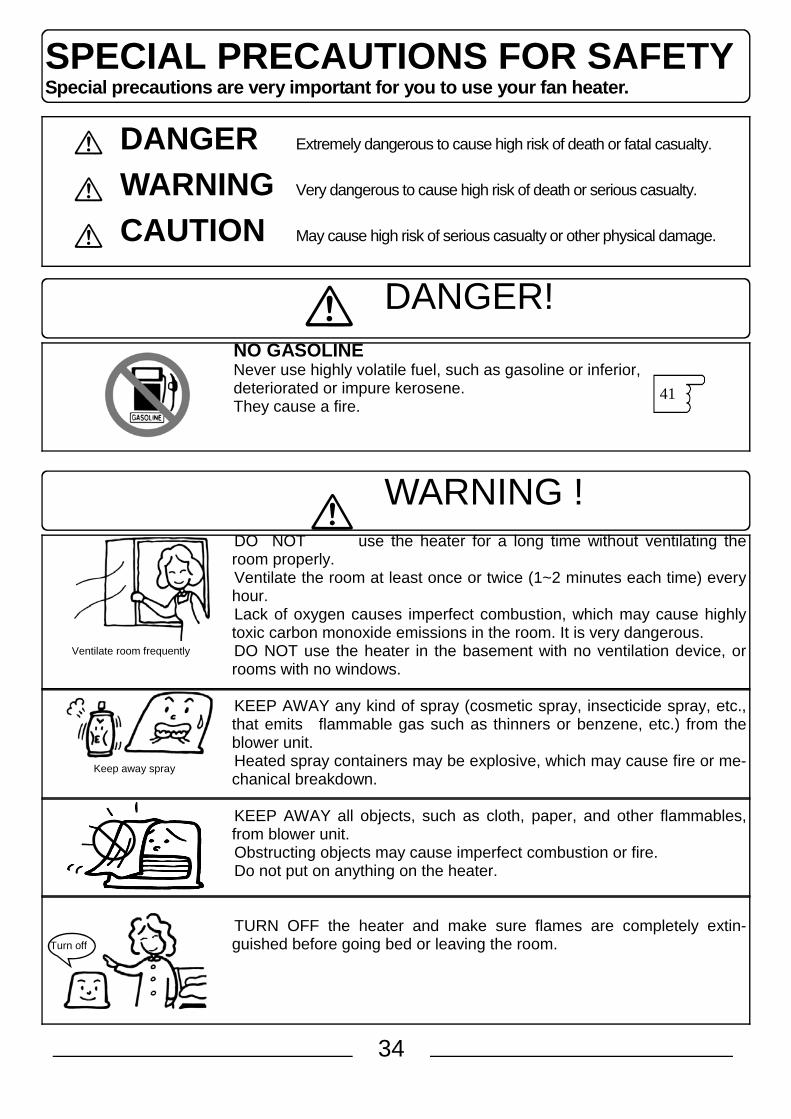
SPECIAL PRECAUTIONS FOR SAFETY Special precautions are very important for you to use your fan heater.
DANGER Extremely dangerous to cause high risk of death or fatal casualty.
WARNING Very dangerous to cause high risk of death or serious casualty.
CAUTION May cause high risk of serious casualty or other physical damage.
DANGER!
NO GASOLINE Never use highly volatile fuel, such as gasoline or inferior, deteriorated or impure kerosene. They cause a fire.
WARNING !
DO NOT use the heater for a long time without ventilating the room properly. Ventilate the room at least once or twice (1~2 minutes each time) every hour. Lack of oxygen causes imperfect combustion, which may cause highly toxic carbon monoxide emissions in the room. It is very dangerous. DO NOT use the heater in the basement with no ventilation device, or rooms with no windows. KEEP AWAY any kind of spray (cosmetic spray, insecticide spray, etc., that emits flammable gas such as thinners or benzene, etc.) from the blower unit. Heated spray containers may be explosive, which may cause fire or me-chanical breakdown. KEEP AWAY all objects, such as cloth, paper, and other flammables, from blower unit. Obstructing objects may cause imperfect combustion or fire. Do not put on anything on the heater. TURN OFF the heater and make sure flames are completely extin-guished before going bed or leaving the room.
41
Ventilate room frequently
Keep away spray
Turn off

35
CHECK the fuel leak. Fasten the fuel tank cap securely. Hold the tank with top-side down to make sure it is not leaking. Leaking fuel can easily catch fire. CLEAN air filter and intake once a week. Dirty air filter may cause imperfect combustion.
DO NOT use the heater in the case extraordi-nary flames, smells, sounds are noticed. DO NOT disassemble the heater unit for repair-ment or conversion purpose. Stop using the heater if the system does not work properly or is damaged. Inappropriate repairment may cause further se-rious problems. EMPTY fuel tank if the heater is unused for a long time, or when it is stored. It must be stored in an upright position, never in a tipped position or on its side. Failure to the instruction may cause fuel leak, and fire.
CAUTION
off
AVOID locations close to drapes of flammable ma-terial. DO NOT put laundries, sofas, too close to the blower unit. Flammable material or objects may cause fire. DO NOT touch the blower grill while heater is on or immediately after use, to avoid fatal burning. Keep children away from them. Protecting Guard is available as an option (CFK-RG12).
AVOID direct exposure to the heated air for a long time of period. Long, direct exposure to the heated air may cause hypothermic burning or dehydration, especially on children and the aged.
ALWAYS TURN OFF the heater before filling with liquid combustible for mobile heater. AVOID fire or heated area when filling with liquid combustible for mobile heater.
58
52
45
Keep away 100 cm or more Flammable material
Kep away children
Very hot part
Keep heater distant away
Heater Fuel tank
Turn off
Air Filter
Clean Air Filter
Fuel is leaking

36
SPECIAL PRECAUTIONS FOR SAFETY
CAUTION HANDLE WITH CARE the power cord.
The power cord mustn't be given stressful force or nothing must be rested on it. Also keep it away from heated blow wind.
Do not hold and pull the cord when unplugging. ENSURE that the electrical socket is properly plugged.
Do not use any damaged socket or worn out cord. It may cause unexpected fire. MAINTAIN the electrical socket clean.
Unplug the socket once a while and wipe out any dust, and check the damage. Dust clog may cause electrical insulation defect and/or unexpected fire. ENSURE when starting timer operation that no flammable material is around the heater. UNPLUG when the heater is not in use.
Also be sure to unplug when cleaning the unit or removing liquid combustible for mobile heater. DO NOT USE THE HEATER;
if the floor surface is not flat and even; in the confined area such as under a mantelpiece; either above or under an unstable shelf; at places where the flammable gases may be generated or accumulate; at the isolated areas where no one is around nearby; at places where strong wind blows, draughts, corridor or near the entrance; at places where it is dusty or damp; in vehicles such as an automobile or a boat; in direct sunlight or at the place where the temperature tends to rise quickly; in places where gas or chemicals (e.g. freon gas, chloride compounds) are used,
such as beauty salons, barber shops, chemical plants, laundries, etc.; at the high locations more than 400 meters above sea level. See adjustment Adjustment is necessary before using the heater. See ̀ Elevation Adjustment'.
Failure to follow any one of above may cause unexpected accident. KEEP all obstructions and flammable materials away from the heater unit. Keep the proper space between the heater unit and flammable walls, following the minimum distances shown on the illustration. Obstructions in front of the air blower may heat up the heater unit, which consequently may distort the plastic components in the system, or may cause the entire breakdown.
CAUTION! Use the heater only on the heat-resistant floor. Heat may cause colour change in a rug texture, or distortions or crackings on the floor surface. Remove dust on the warm air blower (louvers). Burnt dust may smell or may catch fire to cause unexpected accident. Do not use any chemical containing silicone near the heater. Hair conditioners, cosmetics, or polishing chemicals containing silicone may cause flaming disor-der. Do not dry hair with the heater because some shampoos also contain silicones.
100cm or more
15cm or more
15cm or more 100cm or more
100cm or more
52
44

37
LIST OF PARTS External Components *All cords are omitted to simplify the illustration.
FRONT:
Burner unit
I ns pec t i on window
BACK:
POWER: 230 a.c./ 50Hz household use ONLY
Fuel tank cover
Control panel Indicators
Warm air blower (Louver)
Base plate
Drain slot
Room thermo-sensor
Power cord Power plug
Air intake filter (Air intake for combustion)
Warm air intake
Fuel gauge
*Do not lose it.
Gasket (black)
Fuel feeder cap
*Upright position
Tank handle
Fuel tank
54
Fuel receiver
Fuel strainer
Fuel filter

38
LIST OF PARTS Control Panel/ Indicators for SRE 3002 *All indicators are illustrated "lit" status for descriptions.
INDICATOR SELECTOR KEY Temperature, current time, timer-programmed time can be selected to in-dicate.
ODOR-FREE LAMP The lamp is lit: Odor-free system is activating at the Ignition or at the extinction 46
CHILD SAFETY KEY On/off the safety function.
50
TEMPERATURE ADJUSTMENT KEY Use when setting the desired temperature.
higher temperature lower temperature
TIME ADJUSTMENT KEY Use when setting current time and/or the timer.
time ahead time back
47
48 49
POWER SELECTOR KEY Use MIN/AUTO/SAVE for using pur-pose respectively. 47
"ON" KEY (OPERATION LAMP) Use when starting the heater operation. The lamp is lit (red): under operation, pre-heating The lamp is flashing (red) + buzzer: flame is extin-guished and the display shows a code error or an alarm. 56 45
OFF BUTTON Stops the operation.
38
TIMER CONTROL KEY (TIMER LAMP) For time setting of TIMER, the switch TIMER is light green: timer operation is in stand-by status.
49 45
TIMING
TIMING KEY Use when setting the desired com-bustion hour after the unit operates at programmed time. At each pressing of timing key, indi-cation changes as follows: [--h] Combustion goes as follows; [10h] 10 hours of combustion [ 9h] 9 hours of combustion . . . . . . [ 1h] 1 hour of combustion
49

39
LIST OF PARTS Control Panel/ Indicators for SRE 4602 *All indicators are illustrated "lit" status for descriptions.
POWER SELECTOR KEY Use MIN/AUTO/SAVE for using purpose respectively.
ODOR-FREE LAMP The lamp is lit: Odor-free system is activating at the Ignition or at the ex-tinction
CHILD SAFETY KEY On/off the safety function.
TEMPERATURE ADJUSTMENT KEY Use when setting the desired temperature. + higher temperature - lower temperature TIME ADJUSTMENT KEY Use when setting current time and/or the timer. + time ahead - time back
INDICATOR SELECTOR KEY Temperature, current time, timer-programmed time can be selected to in-dicate.
"ON" KEY (OPERATION LAMP) Use when starting the heater operation. The lamp is lit (red): under operation, pre-heating The lamp is flashing (red) + buzzer: flame is extin-guished and the display shows a code error or an alarm.
OFF BUTTON Stops the operation.
SWITCH/TIMER LAMP For time setting, timer on/off. The switch TIMER is light green: timer operation is in stand-by status. 46
50 38
49 45
47
48 49
47
56 45
TIMING
TIMING KEY Use when setting the desired com-bustion hour after the unit operates at programmed time. At each pressing of timing key, indi-cation changes as follows: [--h] Combustion goes as follows; [10h] 10 hours of combustion [ 9h] 9 hours of combustion . . . . . . [ 1h] 1 hour of combustion
49

40
11
CHILD SAFETY LAMP The lamp is lit: the child safety mode is on. 50
DIGITAL INDICATORS Indicates pre-heating, errors, elevation, temperature, current time, and timer-programmed time.
Pre-heating
Errors
Elevation lamp is lit Elevation adjustment is done. Indications will change by pressing INDICATOR SELECTOR.
Temperature lamp is lit Indicates pre-set temperature and
current temperature under auto-matic operation mode.
(Example shows pre-set temperature at 22 and the current temperature at 16)
Time lamp is light off Indicates current time.
Timer-set time lamp is lit Indicate the pre-set time for the
timer.
56
47
48
49
HEAT POWER LAMP Indicates the heat power se-lected. (Example shows AUTO heat power at the current tempera-ture of 20 degrees.)
47
Indication on Fuel filling Flash + Buzzer...
The unit buzzers and the filling sign lights 30 minutes and 5 minutes before the heater is turned off.
Blink + Melody.… The heater is turned off because the fuel is consumed.
Indication on Ventilation Flash + Buzzer....
Ventilating the room is needed. The unit buzzers every 5 min-utes until the ventilation is com-pleted.
Blink + Buzzers....
The heater turned off because the ventilation is insufficient.
45
44

41
PREPARATION PROCEDURES
Unpacking Remove a protection sheet on the top. Open a fuel tank cover, remove the tank stopper to pull out the tank. Remove all the adhesive tapes. Keep the box for the later storage use.
Pre-ignition Preparation and Check Points Level: F Set the heater at even level. F When the heater is located at the positioned level, Auto Shut-off Device may be activated improperly. F When the heater is located at the even level, Auto Shut-off
Device will be automatically set on. Power: Use household currency AC230V-50Hz.
remaining liquid combustible for mobile heater of the previous season; liquid combustible for mobile heater directly sunlighted, or stored in the place with
high temperature. liquid combustible for mobile heater kept in a white polypropylene container, or
in an uncapped container for long time. Always use the proper liquid combustible container. Impurified liquid combustible are:
liquid combustible mixed with even a small amount of any kind of oil (gasoline, thinner, kitchen oil, lubricant, heavy oil, light oil, etc.).
liquid combustible mixed with water or dust. liquid combustible that dehydrate chemical agent or combustion improper was
added. Deteriorated/impurified liquid combustible will cause imperfect combustion and/or
entire system breakdown. CAUTION! In case of accidental use of the deteriorated/impurified liquid combustible... Replace whole content in the fuel tank, and remove all the remaining in the fuel receiver.
current temperature at 12 degrees
When a power socket is plugged, current temperature will be indicated.
42
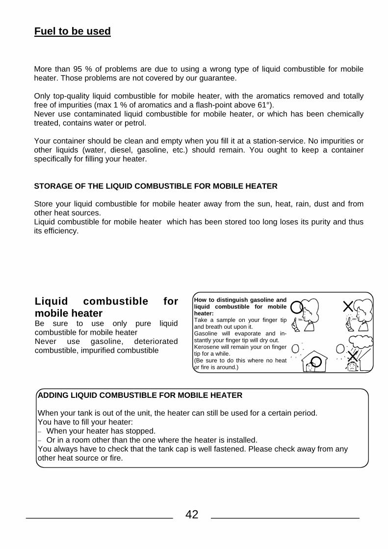
Fuel to be used
More than 95 % of problems are due to using a wrong type of liquid combustible for mobile heater. Those problems are not covered by our guarantee. Only top-quality liquid combustible for mobile heater, with the aromatics removed and totally free of impurities (max 1 % of aromatics and a flash-point above 61°). Never use contaminated liquid combustible for mobile heater, or which has been chemically treated, contains water or petrol. Your container should be clean and empty when you fill it at a station-service. No impurities or other liquids (water, diesel, gasoline, etc.) should remain. You ought to keep a container specifically for filling your heater. STORAGE OF THE LIQUID COMBUSTIBLE FOR MOBILE HEATER Store your liquid combustible for mobile heater away from the sun, heat, rain, dust and from other heat sources. Liquid combustible for mobile heater which has been stored too long loses its purity and thus its efficiency.
ADDING LIQUID COMBUSTIBLE FOR MOBILE HEATER When your tank is out of the unit, the heater can still be used for a certain period. You have to fill your heater: − When your heater has stopped. − Or in a room other than the one where the heater is installed. You always have to check that the tank cap is well fastened. Please check away from any other heat source or fire.
How to distinguish gasoline and liquid combustible for mobile heater: Take a sample on your finger tip and breath out upon it. Gasoline will evaporate and in-stantly your finger tip will dry out. Kerosene will remain your on finger tip for a while. (Be sure to do this where no heat or fire is around.)
Liquid combustible for mobile heater Be sure to use only pure liquid combustible for mobile heater Never use gasoline, deteriorated combustible, impurified combustible

43
What is liquid combustible for mobile heater of bad quality or unrefined ?
Long time
* liquid combustible for mobile heater of the last season.
* liquid combustible for mobile heater exposed to the sun or high humidity
* liquid combustible for mobile heater stored in a container not well closed or the colour of the container is not dark.
* liquid combustible for mobile heater mixed with some water or dust or an other type of fuel different from kerosene.
* liquid combustible for mobile heater of bad quality has a yellow colour and a acid smell. * Use up fuel within the season. WHAT HAPPENED IF YOU USE BAD LIQUID COMBUSTIBLE FOR MOBILE HEATER ? * Tar form in evaporator, and ignition and extinguishment become difficult. * May cause abnormal combustion and shut off during operation. WHAT YOU HAVE TO DO IF YOU INADVERTENTLY USE LIQUID COMBUSTIBLE FOR MOBILE HEATER OF BAD QUALITY? * Drain the combustible in both fuel tank and fixed tank and clean with clean liquid combustible
for mobile heater 2 or 3 times. Note : Repair service for trouble due to deteriorate / impure liquid combustible for mobile
heater should be charged to user even within warranty period.
Season
Water, dust, gazoline, oil,...

44
Fuel filling *Be sure that flames are completely extinguished before filling the liquid combustible for mobile heater. * Your heater will turn off automatically when you take out the mobil tank. The display will indicate E4. 1. Lift fuel tank cover and pull out the tank. Put the tank on the ground. Tank removed, your heater will automatically shutt off.
Place the fuel tank on a floor. Upright two tank handles and hold them together as illus-trated to pull up and remove the filler cap (for SRE 4602) or
unscrew the stopper (SRE 3002) 2. Fill the tank.
Place the tank on a flat, even floor, and use a fuel feeder. Stop filling when a colour of a half of the fuel gauge turns from silver to black.
3. Fasten the cap.
Match marks on the cap and the tank, turn the cap clock-wise as pushing it down hard, until it completely stops. Ensure that mark and mark are matched.
*Improper fastening may cause leaks and a fire. Wipe out any drops of kerosene. Hold the tank upside down to check leaks.
*When carrying the tank, always hold two handles together for the safety.
*Avoid hitting the filler cap to be distorted. Distorted filler cap may cause liquid combustible leaks.
*Be careful not to drop the tank. 4. Replace the tank.
Carefully replace the filled tank into tank compartment. Elevation Adjustment Because the low air pressure makes combustion imperfect, it is necessary to adjust the system ac-cordingly. Adjustment should be done with an electrical socket plugged but in off-operation status. Press <TIMER CONTROL>, and <CHILD SAFETY> keys all together for 3 seconds. Nothing changes even pressing longer. Indication changes at each press as illustrated: *Once adjustment is completed, the data will remain in the memory even after it is unplugged.
1. Push down hard the filler cap. 2. Turn the handles counterclockwise.
* Filling over the halfway may cause overflow when fastening the cap.
* Keep water and dust away from fuel tank.
CAUTION! Be sure to wipe out any oil drop on and around the cap and threads with cloth.
Be careful not to stick fingers into gaps to prevent from being injured.
1 2
1 2
For use at 400~750 m elevation
For use at 740~1250 m elevation
For use at 400 m and lower elevation (For ordinary use)
45
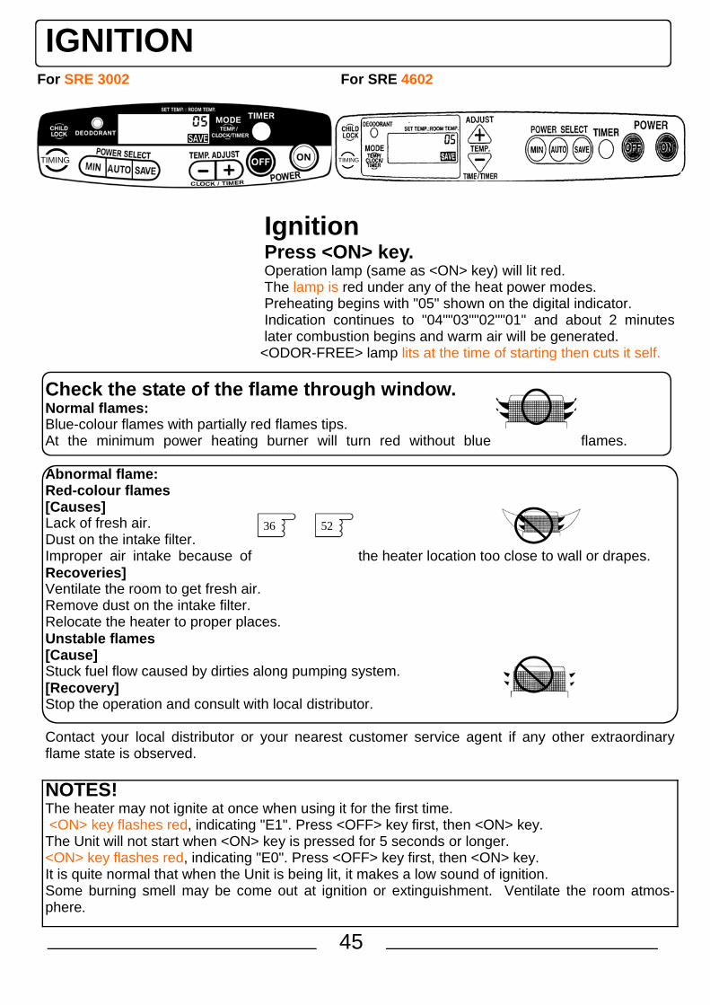
Ignition Press <ON> key. Operation lamp (same as <ON> key) will lit red. The lamp is red under any of the heat power modes. Preheating begins with "05" shown on the digital indicator. Indication continues to "04""03""02""01" and about 2 minutes later combustion begins and warm air will be generated.
<ODOR-FREE> lamp lits at the time of starting then cuts it self.
Check the state of the flame through window. Normal flames: Blue-colour flames with partially red flames tips. At the minimum power heating burner will turn red without blue flames. Abnormal flame: Red-colour flames [Causes] Lack of fresh air. Dust on the intake filter. Improper air intake because of the heater location too close to wall or drapes. Recoveries] Ventilate the room to get fresh air. Remove dust on the intake filter. Relocate the heater to proper places. Unstable flames [Cause] Stuck fuel flow caused by dirties along pumping system. [Recovery] Stop the operation and consult with local distributor. Contact your local distributor or your nearest customer service agent if any other extraordinary flame state is observed. NOTES! The heater may not ignite at once when using it for the first time. <ON> key flashes red, indicating "E1". Press <OFF> key first, then <ON> key. The Unit will not start when <ON> key is pressed for 5 seconds or longer. <ON> key flashes red, indicating "E0". Press <OFF> key first, then <ON> key. It is quite normal that when the Unit is being lit, it makes a low sound of ignition. Some burning smell may be come out at ignition or extinguishment. Ventilate the room atmos-phere.
52 36
For SRE 3002 For SRE 4602
IGNITION
TIMING TIMING

46
TURNING OFF Press <OFF> key.
Flames go out, and "ON" lamp goes off. Odor-free lamp stay lits during the cycle of extinction and then cuts off.
*Fan rotation may sound louder as the odor-free system is activated. *Digital indicators will indicate whatever the modes selected during operation.
Extinguishment will be completed when the odor-free lamp goes off and the fan continues to run for about 3 minutes to cool down the Unit.
TURNING OFF
CAUTION: NEVER try to switch off your heater by hitting, shoving or taking out the plug. NOTES: Odor-free system will not work when flames go out in false extinguishment.
After ignition, your heater will function at full power during +/- 5 minutes; the temperature will begin regulating after this 15 min period.

47
ROOM TEMPERATURE ADJUSTMENT
ROOM TEMPERATURE ADJUSTMENT The Unit is preset to bring room temperature to 20 centigrade. This is adjustable by pressing <TEMP. ADJUST SELECTOR> keys. The system will automatically adjust the heat power according to the programmed temperature. Press <-(down)> key or <+(up)> key of <TEMPERATURE> key for de-sired room temperature. MODE SELECTION Depending on your selection , you can select three modes, SAVE , AUTO and MINI. In SAVE mode The heater automatically stop the operation when the room tempera-ture goes up 2 centigrade higher than the setting temperature.
NOTES: Preset temperature may not necessarily be in accordance with the actual temperature indicated on the room thermometer, depending on the conditions. The room temperature may reach above the programmed temperature; this may happen with high outdoor temperatures or a small room.
SAVE AUTO MIN
For SRE 3002
For SRE 4602
Max Output
~
Min Output
~
Off
Max Output
~
Min Output
TIMING
TIMING
Min Output

48
Time Adjustment Time Adjustment
Time adjustment is available both on- and off-operation status. Ex. To adjust to PM. 8:35
1. Press on switch MODE one or two times for the hour appear on the electronic display. The display indicate “-:- - “
2. Press the button - or + to select the hour Press the key once and digital display will indicate «0:00», then the current time. Time figure can be changed from the second press.
3. Adjust to the correct time Minutes can be adjusted by one minute at each press. Keep the key pressed for a few seconds and the figure will continue to change. After the minute reaches 10, figure changes by every ten minutes as shown in the illustra-tion.
Time figures when < + (up) > I s pressed.
Press the key one at a time for the minute adjustment.
4. Adjustment is now completed. Wait few second without press and the selection of the hour will be memorised

49
TIMER OPERATION
TIMER OPERATION Timer operation is available only after the current time is entered. *When < TIMER CONTROL > key is pressed, buzzer sounds as the current time is displayed. EX: To program AM. 6:35
1. Press < ON > key. Operation lamp lits.
*This step is not necessary while the heater is already in operation.
2. Press < TIMER CONTROL > key. Operation stops and the operation lamp goes off. Timer operation lamp lits, and digital indicator shows restarting time 6:00.
3. Enter restarting time Time indication changes by minute at each pressing of time key. Press the key for a few seconds and the figure will continue to change. After the minutes reaches 10, figure changes by every ten minutes. Press the key one at a time for minute adjustment.
4. Press <TIMING> key, and program the working duration. [--h] indicates the combustion goes on without stop, [10h] indicates 10 hours, [9h] does 9 hours, ... and [1h] does 1 hour of combustion.
5. Timer programming is now completed. *Confirm that the timer lamp is lit. *Digital indicator shows the mode selected.
The Unit restarts at the programmed time.
NOTES: The stating hour of the TIMER can be modified when you want. You must only press on the switch MODE and adjust the hour with the button + and –.
For SRE 3002
For SRE 4602
TIMING
TIMING

50
Timer Release Press <OFF> key.
Timer lamp goes off. Once the restarting time is programmed, the heater can be operated thereafter with following procedure: 1. Press < ON > key.
Operation lamp lits. *This step is not necessary while the heater is already in operation.
2. Press < TIMER CONTROL > key.
The Unit restarts at the programmed time. To restart the Unit before the programmed time, press timer control key.
NOTES: Blackouts and earthquakes after timer programming: In case of power failure caused by blackouts, programmed data will be cancelled, and after power is back, digital indicator will show the current room temperature. In case of power failure caused by earthquakes, digital indicator will show "E4", and red operation lamp will flash. In either case, timer lamp is not on. Press <OFF> key, then follow the procedure for current time adjustment and timer programming.
CAUTION!: Be sure to clear all flammable materials around the heater.
CHILD SAFETY DEVICES CHILD SAFETY DEVICES Press <CHILD SAFETY> key for 3 seconds. "Child safety" is indicated with peep sound. Under <ON> operation: All functions except extinguishment [ off ] key are re-stricted. Under <OFF> operation: All functions except cancellation of child safety sys-tem are restricted. Cancellation of child safety system can be done by pressing <CHILD SAFETY> key for 3 seconds. "Child safety" indication goes off. CAUTION! If any error code is indicated, cancel the child safety system and then follow steps and 56 57

51
IMPORTANT − Use your heater in a room which is properly ventilated and free of inflammable vapours. − Each room that the heater is used in must be adequately ventilated (the ventilator window must
have min a surface area of 50 cm²). − Do not use your heater in too small a room : 3000 watts : min 46 M3, 4600 watts : min 71 M3. − In case of damage to the power cord, it must only be replaced by a workshop recognized by the
manufacturer (or distributor). − Whenever any of these safety systems is triggered, ventilate the room and check and eliminate
the cause, and then reignite. Never disconnect electric parts and never replace it with non ap-proved parts.
− Never disconnect neither the valve of the combustion control nor the combustion system.
Always preserve a minimum clearance of 1 meter from other objects
SECURITY ADVERTISMENT
DO NOT USE YOUR HEATER IN ROOMS SITUATED UNDER THE FLOOR LEVEL.
AIR-SENSOR DETECTOR This heater has been designed with an Air-sensor device based on the direct measurement of CO2 rate in the room. Abnormal conditions of use of your heater (bad ventilation or too small a room) will automatically pro-voke the shut-off of your heater and the Air-sensor light will come on.
IMPORTANT Any tampering with or modification to the safety system is prohibited. Apart from invalidating the guarantee, this would risk causing a failure of the system which is there for your safety.
RESTRICTION ON USE This heater may not be used in rooms which are hermetically sealed, such as caravans, boats, pas-senger compartments of vehicles etc. The utilisation of this heater in a public room must be the subject of a reglemented step. You must take information close to competent autorities.
WARNING for the replacement of the power cord
In case of damage to the power cord, it must only be replaced by a workshop approved by the manufacturer (or distributor) because some tools are necessary.
52
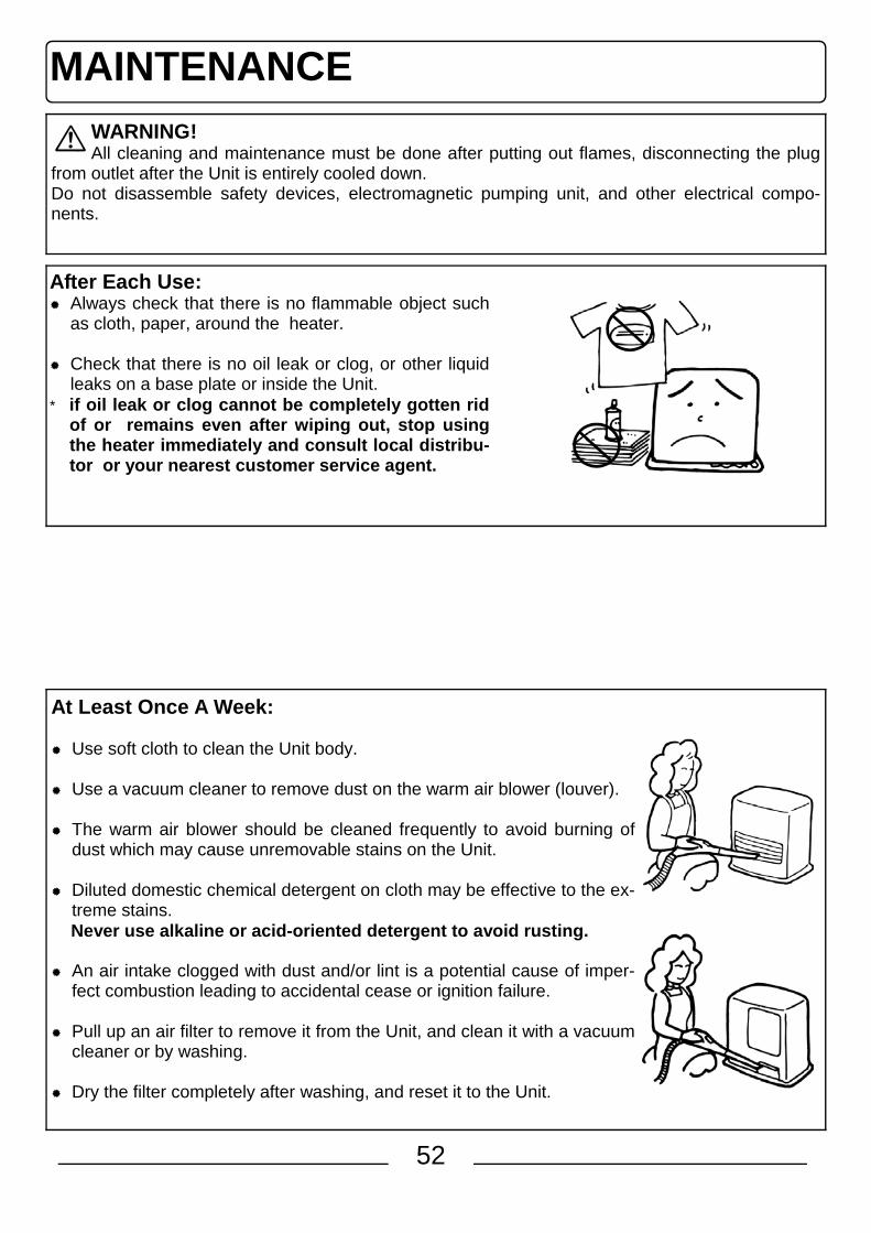
MAINTENANCE WARNING! All cleaning and maintenance must be done after putting out flames, disconnecting the plug
from outlet after the Unit is entirely cooled down. Do not disassemble safety devices, electromagnetic pumping unit, and other electrical compo-nents.
After Each Use: Always check that there is no flammable object such as cloth, paper, around the heater.
Check that there is no oil leak or clog, or other liquid leaks on a base plate or inside the Unit.
* if oil leak or clog cannot be completely gotten rid of or remains even after wiping out, stop using the heater immediately and consult local distribu-tor or your nearest customer service agent.
At Least Once A Week:
Use soft cloth to clean the Unit body.
Use a vacuum cleaner to remove dust on the warm air blower (louver).
The warm air blower should be cleaned frequently to avoid burning of dust which may cause unremovable stains on the Unit.
Diluted domestic chemical detergent on cloth may be effective to the ex-treme stains. Never use alkaline or acid-oriented detergent to avoid rusting.
An air intake clogged with dust and/or lint is a potential cause of imper-fect combustion leading to accidental cease or ignition failure.
Pull up an air filter to remove it from the Unit, and clean it with a vacuum cleaner or by washing.
Dry the filter completely after washing, and reset it to the Unit.

53
WARNING! Remove dust or metallics, if any, on the space between
blades. It may catch fire (known as "a tracking phenomenon").
At Least Once A Year: Shove the Unit while it is operating, to check that Auto Shut-off Device functions properly and flames go out. (Confirm that digital indicator displays "E4" code.) At Least Once A Month: Dust or water in a fuel filter may prevent smooth flow of kerosene, which potentially leads to ignition failure or accidental cease. 1. Unplug the Unit. Remove fuel tank out of the Unit. 2. Remove fuel strainer from fuel receiver. Be careful not to drop any dust or water onto the receiver. 3. Rinse the fuel strainer with clean, pure liquid combustible for mobile heater. Never rinse it with water. 4. Reset the fuel strainer to the Unit. Wipe out any oil remaining, if any, on the receiver before resetting the fuel strainer.
Replacement of Fuel Filter: Fuel filter is available at your local store. Replace the fuel filter with new one if usual cleaning procedure does not work. 1. Place a fuel strainer upside down. Tap the base of the strainer and remove the filter. 2. Set a new filter by fixing four clutches onto the strainer.

54
REGULAR MAINTENANCE
MAINTENANCE WARNING! When pumping fuel out of the tank, be sure to put out all flames, and unplug the Unit, other-
wise it may cause imperfect combustion.
Water Drain/Oil Drain of Fuel Receiver In such case that water is mixed into fuel, and that stops combustion, take the following steps to drain water. 1. Unplug the Unit. 2. Remove fuel strainer.
See the steps for the cleaning of fuel filter on the previous page. 3. Drain water/liquid combustible for mobile heater.
Insert a fuel feeder through a hole on the back panel, and pump out the content.
4. Replace the fuel strainer.
Wipe out dripped water/oil around the strainer. Absorb wasted water/oil into used newspapers and dispose them, If imperfect combustion remains despite of the above procedure, contact your local distributor or the nearest customer service agent.
It is recommendable to conduct the following regular maintenance at least once every two years.
Every component parts of the Unit goes inferior in quality as time passes. It is suggested that regular check-up be taken once every two years so as to maintain the Unit at
its best. For more details on regular maintenance, contact your local distributor or the nearest customer service agent.
Component parts subject to replacement: Following items are tend to wear out in the long term of use; .......Packing materials, fuel filter Following items are tend to be affected by poor quality oils; .......Electromagnetic pump, oil duct, burner body, frame rods, fuel filer, burner head (metal net)
FRONT

55
TROUBLE-SHOOTING Guide The following phenomena may arise during normal operation. You should check the potential causes before consulting your local distributor.
12
Description Cause & Solution
Ignition And E
xtinguishment P
rocesses
At the tim
e of the first use after the purchase, of the season, or after the H
eater has not been used for som
e time.
Smoke and smell come out from the Unit
Floor and wall covering and/or dust may be burning. Ventilate the room for about 10 ~ 15 minutes to let smoke and smell go out and bring your heater to SAV.
Electromagnetic pump makes jit-tering sound, or flames are not stable.
Unnecessary air bubble may arise in the pumping system. As air bubble disappears, flames will be sta-ble.
After repeating ignitions and ex-tinguishments, fuel gas over flows to accidentally put out flames, or emits smell.
Sufficient fuel may not have reached the burner unit. If error code "E1" is indicated on the digital indicator, press <OFF> key first, then <ON> key.
Sometimes small sounds comes out. Sounds are caused by metal expansion and con-traction. They are all normal.
The Unit does not reignite instantaneously once extinguished.
It requires 1 to 2 minutes of preheating.
During C
ombustion
Burner head turns red. It turns red at minimum heating power. It is normal unless there is false ignition or flames accidentally go out.
Flames glow brilliant reddish orange. They usually glow when heated and it is normal. This happens especially under the following circum-stances: The Unit is used in salty air, such as near the sea-side. The Unit is used in dusty air. The Unit is used in a humid environment. The Unit is used along with a ultrasonic humidifier.
There is a running-water-like sound or a bub-bling sound.
This happens when fuel flows from the fuel tank to the fuel receiver. It is normal.
During Tim
er-Program
med O
pera-
Timer cannot be programmed correctly. Current time may not be adjusted.
The Unit does not restart at the programmed time.
It may not work properly if there was power failure, earthquake or any other form of physical shock. Set the timer program again. Check if the entered time is correct.
Others
Fuel tank cap is loose, resulted from clogging dust or worn out packing. There may be dust and/or water clogged in the fuel filter. Clean and remove them. Child safety device may be set. Release the function.
Fuel leaks from fuel tank. Fuel indicator lamp flashes and combustion does not occur even if the fuel tank is full. No response to key operation.
37 44
53
50
48

56
TROUBLE-SHOOTING Guide Error codes along with lamp lights indicates malfunctions.
Error Codes/ Lamps Indications (Devices/systems triggered)
<ON> key has been pressed for longer than 5 seconds.
Ignition failure or state of flames is unstable. (Safety Ignition System has been triggered.) Unnecessary water in the Unit. (Safety Ignition System has been triggered.)
State of flames became unstable and flames abruptly go out. (Combustion Control System has been triggered.) Unnecessary water or scale in the drains in the Unit. (Combustion Control System has been triggered.)
Earthquakes (seismic scale 5 or larger), strong impact on the Unit (Auto shut-off Device has been triggered.) The mobil tank is not in his place.
Overheat inside the Unit. (Anti-overheat device has been triggered.)
Warm air blower (louver) is blocked, resulting overheating.
All indication lamps are glows:
Plug is not properly in place. Power failure (Safety Device has been triggered.)
<fan-mark> lamp glows / flashes :
Air intake filter is clogged with dust. (Combustion Stabilizer has been triggered.) Ventilation required. (Combustion Stabilizer has been triggered.)
<FUEL> lamp glow / flashes : No fuel. Unnecessary dust and/or water in fuel tank, fuel receiver, or fuel filter.
For SRE 3002
For SRE 4602 TIMING
TIMING

57
*Odor-free System will not be activated when flames go out because of false operation.
If recovery is unsuccessful or other error codes not listed below were shown, unplug the Unit once and then place plug properly again, and press <ON> key.
If recovery is still unsuccessful, contact your local distributor or the nearest customer service agent.
Recovery Procedures Press <OFF> key first, then <ON> key.
Press <OFF> key first, then <ON> key. Remove water from fuel receiver.
Clean air filter. Remove water from fuel receiver.
Check that the Unit is placed on flat and even ground surface and that its surrounding is safe.
Wait till the Unit cools down and clean the warm air intake. Remove blocking object, if any, from the warm air blower (louver).
Remove blocking object, if any.
Plug properly in power outlet. Press <OFF> key first and then <ON> key, after power resumes.
Ventilate the room, and clean the air intake filter. Though Combustion Stabilizer is designed for the safety purpose, it is
Refill after pressing <OFF> key, and then press <ON> to restart. Clean fuel tank. Clean fuel filter. Drain water from fuel receiver, and clean it.
54
52
54
41
52
34
36
52
34
44
53
54

58
REPLACEMENT
In case you need any parts replacement, contact your nearest customer service agent. *It is user's liability to use specified parts of our product. Any damage to the product or operational failure due to the false parts replacement is subject to
the user's liability.
STORAGE 1. Unplug the Unit. 2. Empty fuel tank and fuel receiver. Remaining liquid
may cause rust or metal erosion. 3. Clean the Unit body , air intake filter and warm air
intake with dry cloth. 4. Check every part of the Unit for any dam-
age. If any, ask for repairment. 5. Put the Unit into its box and humidity-free storage
area. Keep it in an up- right position, never in a tipped position or on its side.
54
52
FRONT
Unit Fuel feeder

59
SPECIFICATIONS SPECIFICATIONS KERO
MODELE SRE 3002/ FR 32 SRE 4602 / FR 46
Type Gasification at direct injection
Ignition Coil high voltage
Fuel max Liquid combustible for mobile heater
Fuel consumption MAX 250 383
(g/h) Average 158 236
MIN 65 90
Fuel consumption MAX 0.32 l/h 0.49 l/h
(l/h Average 0.20 l/h 0.28 l/h
MIN 0.08 l/h 0.11 l/h
Nominal output MAX 3000 4600
(Watt) Average 1890 2840
MIN 775 1080
Fuel tank capacity (L) 4.0 L 7.1 L
Continuous combustion capacity
MAX 49.4 h 64.5 h
MIN 12.5 h 14.5 h
Suitable room size in m³ MAX
120 184
Unit overall dimensions (HxWxD) mm 415x400x300 455x500x310
Weight kg 10.8 kg 13.6 kg
Voltage and frequency 230V Mono phase, 50HZ
Rated power consumption(W) 30 W 35 W
Fuse Tube type 6.3 A
Safety devices Auto Shut-off Device, Anti-Overheat Device, CO2 Detector, Presence of tank detector, Power Failure Safety Device, Combustion Stabilizer, Safety Ignition System, Combustion Control System