
SR20 Series Features - La empresa | Niulira 500 (“J” dimension) Suitable for all materials and...
32
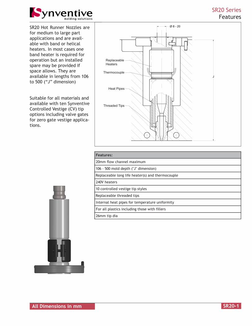
SR20 Hot Runner Nozzles are for medium to large part applications and are avail- able with band or helical heaters. In most cases one band heater is required for operation but an installed spare may be provided if space allows. They are available in lengths from 106 to 500 (“J” dimension) Suitable for all materials and available with ten Synventive Controlled Vestige (CV) tip options including valve gates for zero gate vestige applica- tions. SR20-1 SR20 Series Features J Ø 8 - 20 Threaded Tips Thermocouple Heat Pipes Replaceable Heaters : s e r u t a e F m u m i x a m l e n n a h c w o l f m m 0 2 ) n o i s n e m i d " J " ( h t p e d d l o m 0 0 5 - 6 0 1 e l p u o c o m r e h t d n a ) s ( r e t a e h e f i l g n o l e l b a e c a l p e R s r e t a e h V 0 4 2 s e l y t s p i t e g i t s e v d e l l o r t n o c 0 1 s p i t d e d a e r h t e l b a e c a l p e R y t i m r o f i n u e r u t a r e p m e t r o f s e p i p t a e h l a n r e t n I s r e l l i f h t i w e s o h t g n i d u l c n i s c i t s a l p l l a r o F a i d p i t m m 6 2 All Dimensions in mm
-
Upload
phunghuong -
Category
Documents
-
view
222 -
download
2
Transcript of SR20 Series Features - La empresa | Niulira 500 (“J” dimension) Suitable for all materials and...
SR20 Hot Runner Nozzles arefor medium to large partapplications and are avail-able with band or helicalheaters. In most cases oneband heater is required foroperation but an installedspare may be provided ifspace allows. They areavailable in lengths from 106to 500 (“J” dimension)
Suitable for all materials andavailable with ten SynventiveControlled Vestige (CV) tipoptions including valve gatesfor zero gate vestige applica-tions.
SR20-1
SR20 SeriesFeatures
J
Ø 8 - 20
Threaded Tips
Thermocouple
Heat Pipes
ReplaceableHeaters
:serutaeF
mumixamlennahcwolfmm02
)noisnemid"J"(htpeddlom005-601
elpuocomrehtdna)s(retaehefilgnolelbaecalpeR
sretaehV042
selytspitegitsevdellortnoc01
spitdedaerhtelbaecalpeR
ytimrofinuerutarepmetrofsepiptaehlanretnI
srellifhtiwesohtgnidulcniscitsalpllaroF
aidpitmm62
All Dimensions in mm

SR20-2
SR20 Series Heater Options
Ø 82
120
80 single heater145 spare heater installed
Ø 50
Ø 114H6
20 wide x 26 deepwire slot
14
53
Ø 6H6
x 12 deep
J
Ø8-20
With the exception of PA and PBTone heater required for operation.If mold thickness allows a spareband heater will be installed.When using CV11NS and CV21NStip styles the 82 diameter heaterclearance hole depth increaseseliminating the 50mm diameterclearance hole. See SR20-14 andSR20-22.
J Minimum = 106J Maximum = 380
Ø 114H6
20 wide x 26 deepwire slot
14
53
Ø 6H6
x 12 deep
J
For J 195-380 Ø70not required
For J 380-500 Ø70X J/2 deep.
Ø 70
Ø65
Ø8-20
120
Band Heater
Helical HeaterWhen J is greater than 380 twoheaters are required for opera-tion.
J Minimum = 195J Maximum = 500
SR20-3
SR20 SeriesOverview
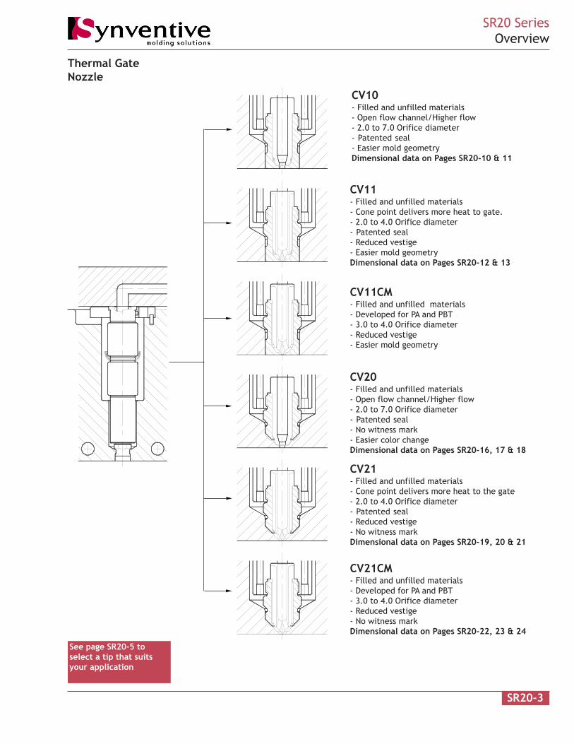
Thermal GateNozzle
See page SR20-5 toselect a tip that suitsyour application
CV10- Filled and unfilled materials- Open flow channel/Higher flow- 2.0 to 7.0 Orifice diameter- Patented seal- Easier mold geometryDimensional data on Pages SR20-10 & 11
CV11- Filled and unfilled materials- Cone point delivers more heat to gate.- 2.0 to 4.0 Orifice diameter- Patented seal- Reduced vestige- Easier mold geometryDimensional data on Pages SR20-12 & 13
CV11CM- Filled and unfilled materials- Developed for PA and PBT- 3.0 to 4.0 Orifice diameter- Reduced vestige- Easier mold geometry
CV21- Filled and unfilled materials- Cone point delivers more heat to the gate- 2.0 to 4.0 Orifice diameter- Patented seal- Reduced vestige- No witness markDimensional data on Pages SR20-19, 20 & 21
CV21CM- Filled and unfilled materials- Developed for PA and PBT- 3.0 to 4.0 Orifice diameter- Reduced vestige- No witness markDimensional data on Pages SR20-22, 23 & 24
CV20- Filled and unfilled materials- Open flow channel/Higher flow- 2.0 to 7.0 Orifice diameter- Patented seal- No witness mark- Easier color changeDimensional data on Pages SR20-16, 17 & 18
SR20-4
SR20 SeriesOverview
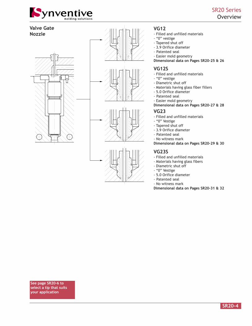
Valve GateNozzle
See page SR20-6 toselect a tip that suitsyour application
VG12- Filled and unfilled materials- “0” vestige- Tapered shut off- 3.9 Orifice diameter- Patented seal- Easier mold geometryDimensional data on Pages SR20-25 & 26
VG23- Filled and unfilled materials- “0” Vestige- Tapered shut off- 3.9 Orifice diameter- Patented seal- No witness markDimensional data on Pages SR20-29 & 30
VG12S- Filled and unfilled materials- “0” vestige- Diametric shut off- Materials having glass fiber fillers- 5.0 Orifice diameter- Patented seal- Easier mold geometryDimensional data on Pages SR20-27 & 28
VG23S- Filled and unfilled materials- Materials having glass fibers- Diametric shut off- “0” Vestige- 5.0 Orifice diameter- Patented seal- No witness markDimensional data on Pages SR20-31 & 32
SR20-5
SR20 SeriesMaterial Compatibility
PE PP PEEK
PPS
PET
PBT
PPO
/PA
PA PPA
POM
PMM
A
ABS
ASA
SAN
PS PC/A
BS
PC PES
PSU
PEI
Add
itiv
es
Semi-crystalline
A
B
C
D
Material
Tip Style
+ + - - - - - - - - + + + + + + + - - -
-++ ----- --+--- --++- -
-++ ++-+- --+-+- --++- -
-++ ----- --+--- --++- -
TPE
PPO
+ -
+ -
+
+
-
-
Amorphous
A
B
C
D
+ + - - - - - - - + - - -+ + + + + + +
------00 -++--++-+- - -
--00 - - - - -- + + + -- + + - --
------++ -++++++++- - - ++
+ +
++
+ +
A
B
C
D
- - - - + + + + - - - -- - -- ----
+++- - +-- - - - -- --- -- - -
+++- - +-- - - - -- --- -- - -
+++- - +-- - - - -- --- -- - - - -
- -
--
- -
A
B
C
D
+ + - - - - - - - 0 - - -+ + + + + + +
------++ 0 +++-+++ -- --
--+---++ 0 +++--+- -- --
+-+ + ++ + + --- +0 - -+ + + - -
+ -
+ -
-+
+ -
A
B
C
D
+ + - - - - - - - + - - -0 + + + + + +
------++ 0 00++-0 -+- --
--+ + - - - - -0- + 0 00 -+ + - -
--++ ---- 0+- 0 - +- -0 0 -- ++
+ +
++
+ +
A
B
C
D
- - - - + + + + - - - -- - -- ----
+++- - +-- - - - -- --- -- - -
+++- - +-- - - - -- --- -- - -
+++- - +-- - - - -- --- -- - - - -
- -
--
- -
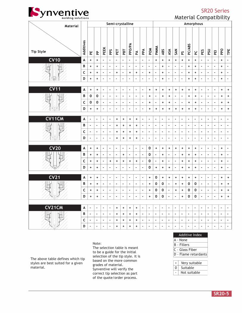
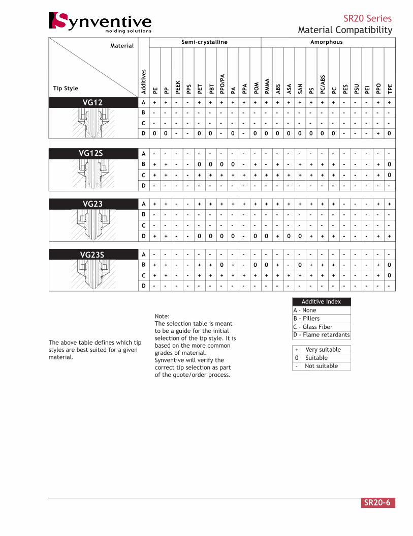
The above table defines which tipstyles are best suited for a givenmaterial.
Note:The selection table is meantto be a guide for the initialselection of the tip style. It isbased on the more commongrades of material.Synventive will verify thecorrect tip selection as partof the quote/order process.
Additive IndexA - NoneB - FillersC - Glass FiberD - Flame retardants
+ Very suitable0 Suitable- Not suitable
CV10
CV11
CV20
CV21
CV11CM
CV21CM
SR20-6
SR20 SeriesMaterial Compatibility
PE PP PEEK
PPS
PET
PBT
PPO
/PA
PA PPA
POM
PMM
A
ABS
ASA
SAN
PS PC/A
BS
PC PES
PSU
PEI
Add
itiv
es
Semi-crystalline
A
B
C
D
Material
Tip Style
+ + - - + + + + + + + + - - -
- ----- ----- --- -
-00 0-00- 00- --00 -
+++ ++
- - - --
---- - - - - - - -- - -- - - - --
00 00
TPE
PPO
--
+ 0
+
-
+
-
Amorphous
A
B
C
D
-++ 0000- -+- --++ --+ ++
+-++ + ++- + + +++ -++++ --
---- - - - - - - -- - -- - - - --
--- - ---- -- --- ---- - - -
0+
- -
-
+
-
0
A
B
C
D
+ + - - + + + + + + + + - - -
- ----- ----- --- -
-++ 0000- 00- --++ -
+++ ++
- - - --
---- - - - - - - -- - -- - - - --
0+ +0
--
+ +
+
-
+
-
A
B
C
D
-++ +0++- 00- --++ --+ +0
+-++ + ++- + + +++ -++++ --
---- - - - - - - -- - -- - - - --
--- - ---- -- --- ---- - - -
0+
- -
-
+
-
0
The above table defines which tipstyles are best suited for a givenmaterial.
Note:The selection table is meantto be a guide for the initialselection of the tip style. It isbased on the more commongrades of material.Synventive will verify thecorrect tip selection as partof the quote/order process.
Additive IndexA - NoneB - FillersC - Glass FiberD - Flame retardants
+ Very suitable0 Suitable- Not suitable
VG12
VG12S
VG23S
VG23
SR20-7
SR20 SeriesFlow Rate
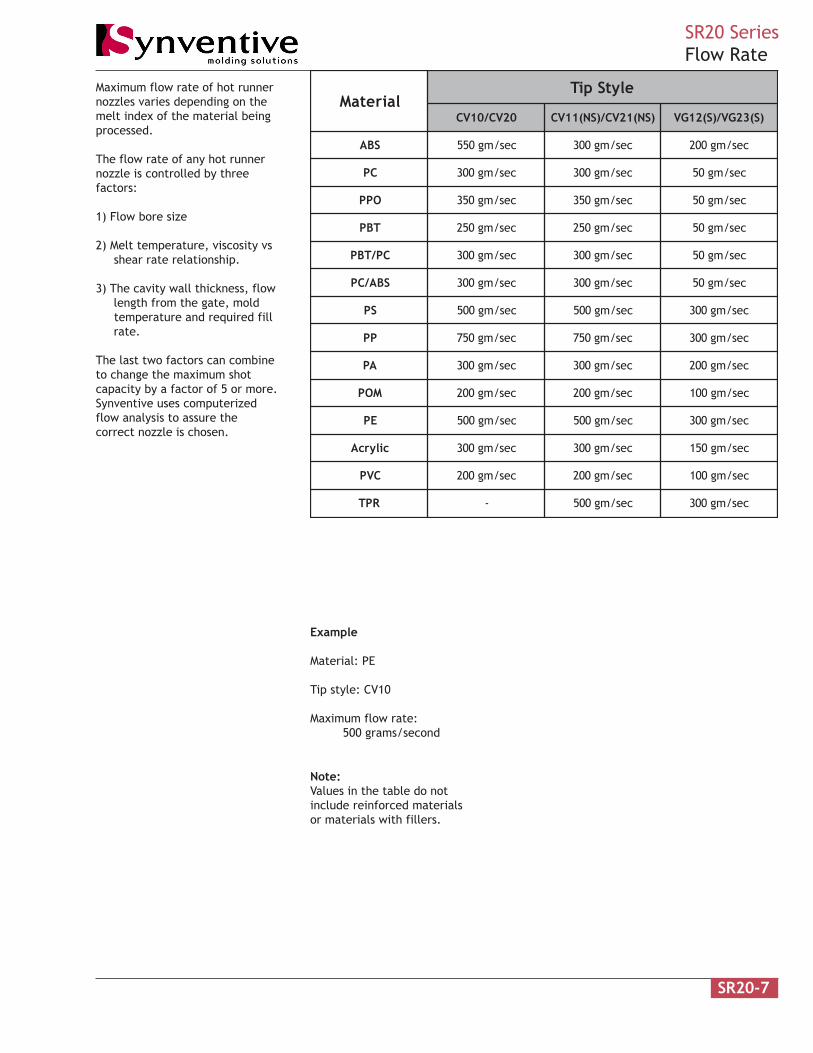
Maximum flow rate of hot runnernozzles varies depending on themelt index of the material beingprocessed.
The flow rate of any hot runnernozzle is controlled by threefactors:
1) Flow bore size
2) Melt temperature, viscosity vs shear rate relationship.
3) The cavity wall thickness, flow length from the gate, mold temperature and required fill rate.
The last two factors can combineto change the maximum shotcapacity by a factor of 5 or more.Synventive uses computerizedflow analysis to assure thecorrect nozzle is chosen.
Example
Material: PE
Tip style: CV10
Maximum flow rate: 500 grams/second
Note:Values in the table do notinclude reinforced materialsor materials with fillers.
lairetaMelytSpiT
02VC/01VC )SN(12VC/)SN(11VC )S(32GV/)S(21GV
SBA ces/mg055 ces/mg003 ces/mg002
CP ces/mg003 ces/mg003 ces/mg05
OPP ces/mg053 ces/mg053 ces/mg05
TBP ces/mg052 ces/mg052 ces/mg05
CP/TBP ces/mg003 ces/mg003 ces/mg05
SBA/CP ces/mg003 ces/mg003 ces/mg05
SP ces/mg005 ces/mg005 ces/mg003
PP ces/mg057 ces/mg057 ces/mg003
AP ces/mg003 ces/mg003 ces/mg002
MOP ces/mg002 ces/mg002 ces/mg001
EP ces/mg005 ces/mg005 ces/mg003
cilyrcA ces/mg003 ces/mg003 ces/mg051
CVP ces/mg002 ces/mg002 ces/mg001
RPT - ces/mg005 ces/mg003

SR20-8
SR20 SeriesOrifice Guidelines
This table lists the normal gateorifice required to fill an averagecavity of the listed wall thicknessand surface area.
The orifice diameter is based onthe flow and freeze characteris-tics of each type of plastic at itsnormal processing conditions. It isnot dependent on whether thecavity is fed by a hot or coldrunner.
Some of the listed wall thicknessand surface area combinations arenot applicable to all plasticsbecause of the flow length to wallratios of each material. Consultplastic supplier’s processingrecommendations.
Due to the gate limitations of eachhot runner nozzle, the actual gatemay be slightly smaller or largerthan the tabulated orifice.
Material FactorsUse tabulated orifice for PE, PP, PS,SAN and PUR.
Use tabulated orifice x 1.15 for POM,PC, PPO and ABS.
Use tabulated orifice x 1.30 for Acrylic,PA, PET, and PBT
Use tabulated orifice x 1.50 for PVC.
)hcni(mmenilediuGretemaiDecifirOaerAtraP )hcni(/mmssenkcihtllaW
mmqs hcniqs57.0)30.0(
00.1)40.0(
52.1)50.0(
05.1)60.0(
57.1)70.0(
00.2)80.0(
52.2)90.0(
05.2)01.0(
00.3)31.0(
00.4)61.0(
006 09.0 09.0 09.0 09.0 09.0 09.0 59.0 00.1 21.1 72.1
0.1 530.0 530.0 530.0 530.0 530.0 530.0 730.0 930.0 440.0 050.0
0021 09.0 09.0 09.0 29.0 00.1 50.1 21.1 71.1 23.1 05.1
0.2 530.0 530.0 530.0 630.0 930.0 140.0 440.0 640.0 250.0 950.0
0081 09.0 09.0 59.0 20.1 01.1 71.1 52.1 03.1 74.1 86.1
0.3 530.0 530.0 730.0 040.0 340.0 640.0 940.0 150.0 850.0 660.0
0042 09.0 09.0 20.1 01.1 02.1 52.1 53.1 04.1 85.1 87.1
0.4 530.0 530.0 040.0 340.0 740.0 940.0 350.0 550.0 260.0 070.0
0003 09.0 59.0 70.1 71.1 52.1 23.1 24.1 74.1 56.1 88.1
0.5 530.0 730.0 240.0 640.0 940.0 250.0 650.0 850.0 560.0 470.0
0006 00.1 21.1 72.1 73.1 05.1 85.1 86.1 67.1 89.1 62.2
0.01 830.0 440.0 050.0 450.0 950.0 260.0 660.0 960.0 870.0 980.0
000,21 71.1 23.1 35.1 56.1 87.1 88.1 )00.2 80.2 63.2 76.2
0.02 640.0 250.0 060.0 560.0 070.0 470.0 970.0 280.0 390.0 501.0
000,81 03.1 74.1 86.1 38.1 69.1 60.2 12.2 13.2 26.2 79.2
0.03 150.0 850.0 660.0 270.0 770.0 180.0 780.0 190.0 301.0 711.0
000,42 73.1 85.1 08.1 69.1 01.2 42.2 93.2 94.2 08.2 81.3
0.04 450.0 260.0 170.0 770.0 380.0 880.0 490.0 890.0 011.0 521.0
000,03 54.1 56.1 09.1 60.2 42.2 63.2 15.2 46.2 59.2 53.3
0.05 750.0 560.0 570.0 180.0 880.0 390.0 990.0 401.0 611.0 231.0
000,63 35.1 37.1 89.1 61.2 43.2 64.2 46.2 77.2 01.3 35.3
0.06 060.0 860.0 870.0 580.0 290.0 790.0 401.0 901.0 221.0 931.0
000,24 85.1 08.1 80.2 62.2 14.2 75.2 57.2 78.2 32.3 66.3
0.07 260.0 170.0 280.0 980.0 590.0 101.0 801.0 311.0 721.0 441.0
000,84 56.1 88.1 31.2 43.2 15.2 46.2 28.2 79.2 33.3 97.3
0.08 560.0 470.0 480.0 290.0 990.0 401.0 111.0 711.0 131.0 941.0
000,45 07.1 39.1 12.2 93.2 06.2 27.2 29.2 50.3 34.3 98.3
0.09 760.0 670.0 780.0 490.0 201.0 701.0 511.0 021.0 531.0 351.0
000,06 37.1 89.1 62.2 64.2 46.2 08.2 00.3 21.3 35.3 99.3
0.001 860.0 870.0 980.0 790.0 401.0 011.0 811.0 321.0 931.0 751.0
000,09 39.1 81.2 15.2 27.2 29.2 01.3 03.3 54.3 98.3 24.4
0.021 670.0 680.0 990.0 701.0 511.0 221.0 031.0 631.0 351.0 471.0
000,021 - 63.2 07.2 29.2 01.3 33.3 65.3 37.3 02.4 57.4
0.002 - 390.0 601.0 511.0 421.0 131.0 551.0 741.0 561.0 781.
000,081 - - 79.2 32.3 84.3 86.3 49.3 51.4 26.4 62.5
0.003 - - 711.0 721.0 731.0 541.0 551.0 261.0 281.0 702.0
000,042 - - - 84.3 67.3 89.3 22.4 24.4 89.4 45.5
0.004 - - - 731.0 841. 651.0 661.0 471.0 691.0 812.0
For non-reinforced PA, PET and PBT theminimum orifice diameter should be3.0. For reinforced PA, PET and PBTthe minimum orifice diameter shouldbe 4.0.
Part Area is total outside area and notthe projected area of the part.

SR20-9
SR20 SeriesManifold Integration
TCP
T
J
Preload cold Center LocatorThrust Pad
Metal O-ring
Ø16H6
6
heightRail
65
SR20 hot runner systems aredesigned with a preload betweenthe thrust pads and the mold platesin the cold condition. As themanifold heats an additional sealingforce is created.
The thrust pads are made of a lowconductivity material and shouldonly be replaced with an equivalentSynventive part.
Excessive contact with the mold willcause heat sinks and affect thesystem performance. Contact withthe mold must be limited tospecified areas.
T = Rail height - 6 - 65 (manifold)
Minimum T = 10 (thermal gates)
Minimum rail height = 81 (thermalgates).
Support ring nozzles do not line upwith the sub-runners in the manifoldin the cold condition. As themanifold heats up the manifold sub-runner locations expand to thecorrect location.
elbairaV noitpircseD
T pagriapoT
J htpeddloM
PCT etalppmalcpoT

SR20-10
SR20 SeriesManifold Nozzle
26 Band heater (shown)30.3 Helical heater
H6
6 Contact
2.2 Ø26
19.4Ref
Ø2-7
120J30
6
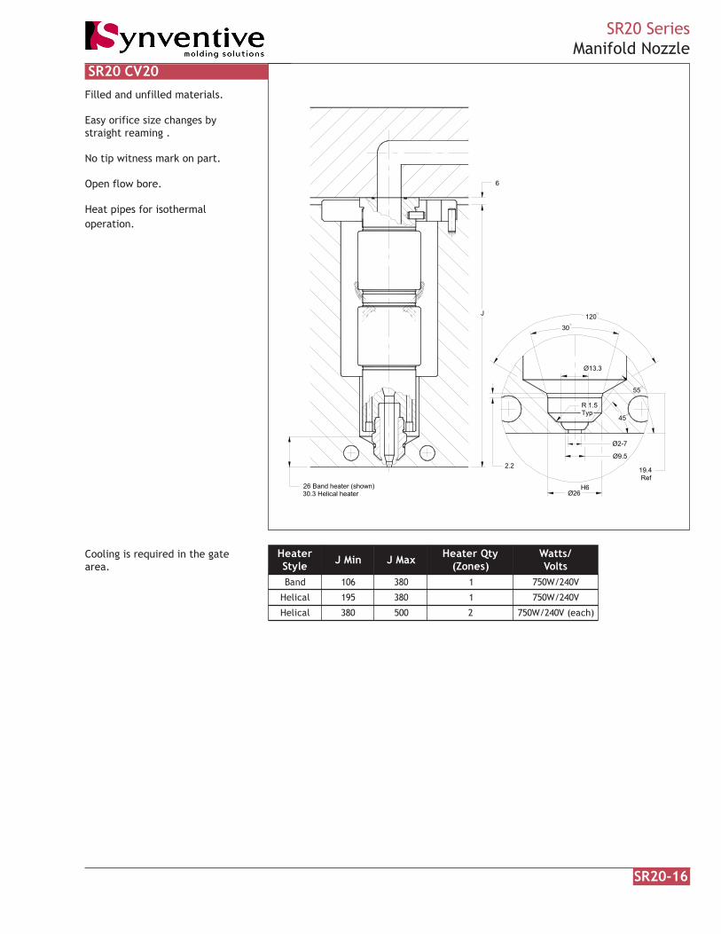
Filled and unfilled materials.
Easy orifice size changes bystraight reaming
Open flow bore
Heat pipes for isothermaloperation.
The front face of the tip must bein contact with plastic.
Cooling is required in the gatearea.
SR20 CV10
retaeHelytS niMJ xaMJ ytQretaeH
)senoZ(/sttaW
stloVdnaB 601 083 1 V042/W057
lacileH 591 083 1 V042/W057
lacileH 083 005 2 )hcae(V042/W057
SR20-11
SR20 SeriesCV10 Angled Mold Contour & Recess
Extension
Angled Mold Contour
K
L
2 Land
1.3 Min
3 Mincontact
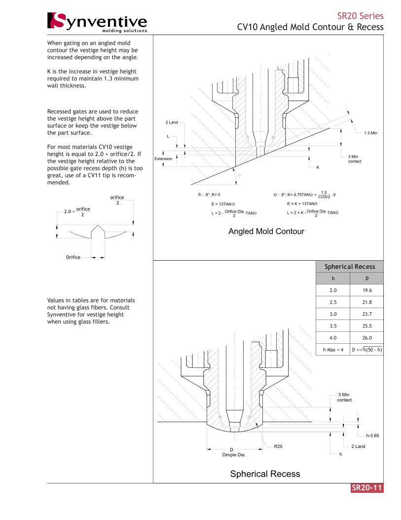
8°; K= 0
E = 13TAN
L = 2 - TANOrifice Dia.2
E = K + 13TAN
L = 2 + K - TANOrifice Dia.2
8°; K= 4.75TAN + -21.3COS
When gating on an angled moldcontour the vestige height may beincreased depending on the angle.
K is the increase in vestige heightrequired to maintain 1.3 minimumwall thickness.
orifice2
2.0 + orifice2
Orifice
Recessed gates are used to reducethe vestige height above the partsurface or keep the vestige belowthe part surface.
For most materials CV10 vestigeheight is equal to 2.0 + orifice/2. Ifthe vestige height relative to thepossible gate recess depth (h) is toogreat, use of a CV11 tip is recom-mended.
Values in tables are for materialsnot having glass fibers. ConsultSynventive for vestige heightwhen using glass fillers.
DDimple Dia. h
2 Land
h-3.65
R25
3 Mincontact
Spherical Recess
sseceRlacirehpS
h D
0.2 6.91
5.2 8.12
0.3 7.32
5.3 5.52
0.4 0.62
4=xaMh )h-05(h=D

SR20-12
SR20 SeriesManifold Nozzle
30.3 Helical heater26 Band heater (shown)
120
2.2 Ø26
6 Contact
H6
30
Ref19.4
Ø2-4
J
6
Land0.130.08
45
2
Filled and unfilled materials.
More heat in the gate area forsemi-crystalline materials
Heat pipes for isothermaloperation.
The front face of the tip must bein contact with plastic.
Cooling is required in the gatearea.
SR20 CV11
retaeHelytS niMJ xaMJ ytQretaeH
)senoZ(/sttaW
stloVdnaB 601 083 1 V042/W057
lacileH 591 083 1 V042/W057
lacileH 083 005 2 )hcae(V042/W057

SR20 SeriesCV11 Angled Mold Contour & Recess
Angled Mold Contour
2
Extension
L
K
1.3 Min
0.080.13
3 Mincontact
Land
E = TAN
L = 0.13 + K - TAN
E = K + 13TAN
L = 0.13 2Orifice Dia.
COS1.39°; K= TANOrifice Dia.
226 + Orifice Dia.
2
Orifice Dia. - 22
Orifice Dia.L = 0.13 + K - TAN
13°; K= 4.75TAN + - 2
E = K + 13TAN
COS
2
1.39 13°; K= 4.75TAN + + TAN - 2
When gating on an angled moldcontour the vestige height may beincreased depending on the angle.
K is the increase in vestige heightrequired to maintain 0.13 land and/or 1.3 minimum wall thickness.
Recessed gates are used to reducethe vestige height above the partsurface or keep the vestige belowthe part surface.
SR20-13
Values in tables are for materialsnot having glass fibers. ConsultSynventive for vestige heightwhen using glass fillers.
d (flat)Orifice
0.080.13
D
Spherical RecessDimple Dia.
R25
Recessh
2
3 Mincontact
d
Land
45 sseceRlacirehpS.aiDecifirO h d D
02.2-00.2 00.1 54.2 02.41
04.2-02.2 60.1 56.2 46.41
06.2-04.2 21.1 58.2 60.51
08.2-06.2 81.1 50.3 74.51
00.3-08.2 62.1 52.3 99.51
02.3-00.3 23.1 54.3 83.61
04.3-02.3 04.1 56.3 78.61
06.3-04.3 64.1 58.3 52.71
08.3-06.3 25.1 50.4 16.71
00.4-08.3 06.1 52.4 70.81h Max = 4.0

SR20-14
SR20 SeriesManifold Nozzle
120
30
30.3 Helical heater26 Band heater (shown)
2.2 Ø26H6
0.080.13 Land
Ø3-4
19.4Ref
2
6 Contact
J
6
45
Filled and unfilled materials.
Developed for PA and PBT.
Heat pipes for isothermaloperation.
The front face of the tip must bein contact with plastic.
Cooling is required in the gatearea.
SR20 CV11CM
retaeHelytS niMJ xaMJ ytQretaeH /sttaW
stloVdnaB 601 083 1 V042/W057
)pit(dnaB 002 083 1 V042/W054
lacileH 591 083 1 V042/W057
lacileH 083 005 2 )hcae(V042/W057
SR20-15
SR20 SeriesCV11CM Angled Mold Contour & Recess
Angled Mold Contour
2
Extension
L
K
1.3 Min
0.080.13
3 Mincontact
Land
Orifice Dia.
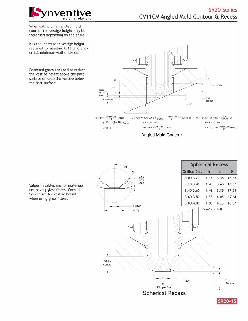
13°; K= 4.75TAN + + TAN - 2
L = 0.13 + K - TAN
2 COS26 + Orifice Dia.E = TAN
L = 0.13
2E = K + 13TAN
2
9°; K= TANOrifice Dia. 1.3COS2
E = K + 13TAN
L = 0.13 + K - TANOrifice Dia.2
13°; K= 4.75TAN + - 2Orifice Dia. - 2 1.3
When gating on an angled moldcontour the vestige height may beincreased depending on the angle.
K is the increase in vestige heightrequired to maintain 0.13 land and/or 1.3 minimum wall thickness.
Recessed gates are used to reducethe vestige height above the partsurface or keep the vestige belowthe part surface.
Values in tables are for materialsnot having glass fibers. ConsultSynventive for vestige heightwhen using glass fillers.
DDimple Dia.
R25Recessh
2
3 Mincontact
d
Spherical Recess
45
Land0.130.08
Orificed (flat)
sseceRlacirehpS.aiDecifirO h d D
02.3-00.3 23.1 54.3 83.61
04.3-02.3 04.1 56.3 78.61
06.3-04.3 64.1 58.3 52.71
08.3-06.3 25.1 50.4 16.71
00.4-08.3 06.1 52.4 70.81
h Max = 4.0
SR20-16
SR20 SeriesManifold Nozzle
Ø2-7
30
120
26 Band heater (shown)30.3 Helical heater
2.2
H6Ø26
45
Ø13.3
R 1.5Typ
Ø9.5
55
6
J
19.4Ref
Filled and unfilled materials.
Easy orifice size changes bystraight reaming .
No tip witness mark on part.
Open flow bore.
Heat pipes for isothermaloperation.
Cooling is required in the gatearea.
SR20 CV20
retaeHelytS niMJ xaMJ ytQretaeH
)senoZ(/sttaW
stloVdnaB 601 083 1 V042/W057
lacileH 591 083 1 V042/W057
lacileH 083 005 2 )hcae(V042/W057
SR20-17
SR20 SeriesCV20 Recess
Conical RecessDimple Dia.
D2 Land
Recessh
30
Ø14
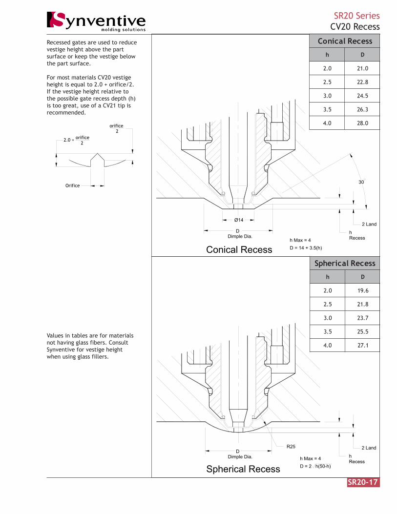
D = 14 + 3.5(h)h Max = 4
Recessed gates are used to reducevestige height above the partsurface or keep the vestige belowthe part surface.
For most materials CV20 vestigeheight is equal to 2.0 + orifice/2.If the vestige height relative tothe possible gate recess depth (h)is too great, use of a CV21 tip isrecommended.
orifice2
2.0 + orifice2
Orifice
Values in tables are for materialsnot having glass fibers. ConsultSynventive for vestige heightwhen using glass fillers.
DDimple Dia.
Recessh
2 Land
Spherical Recess
R25
D = 2 h(50-h)h Max = 4
sseceRlacinoC
h D
0.2 0.12
5.2 8.22
0.3 5.42
5.3 3.62
0.4 0.82
sseceRlacirehpS
h D
0.2 6.91
5.2 8.12
0.3 7.32
5.3 5.52
0.4 1.72
SR20-18
SR20 SeriesCV20 Angled Mold Contour
L
2
K
Land
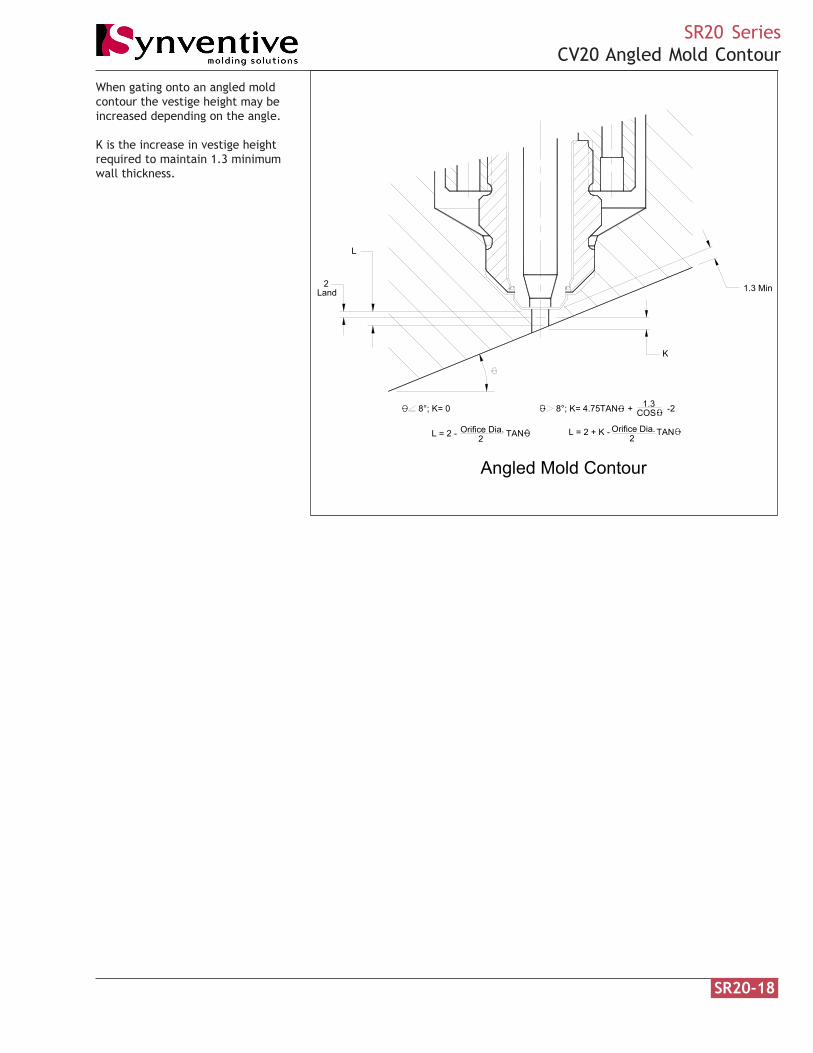
8°; K= 0 8°; K= 4.75TAN + -2COS1.3
Angled Mold Contour
2Orifice Dia.L = 2 - TAN L = 2 + K - TANOrifice Dia.
2
1.3 Min
When gating onto an angled moldcontour the vestige height may beincreased depending on the angle.
K is the increase in vestige heightrequired to maintain 1.3 minimumwall thickness.
SR20-19
SR20 SeriesManifold Nozzle
26 Band heater (shown)30.3 Helical heater
19.4 Ref
120
R 1.5
2.2
Ø26H6
J
Typ
30
Ø13.310
55
45
Ø9.55.6
Ø2-4
6
Land0.130.08
45
2
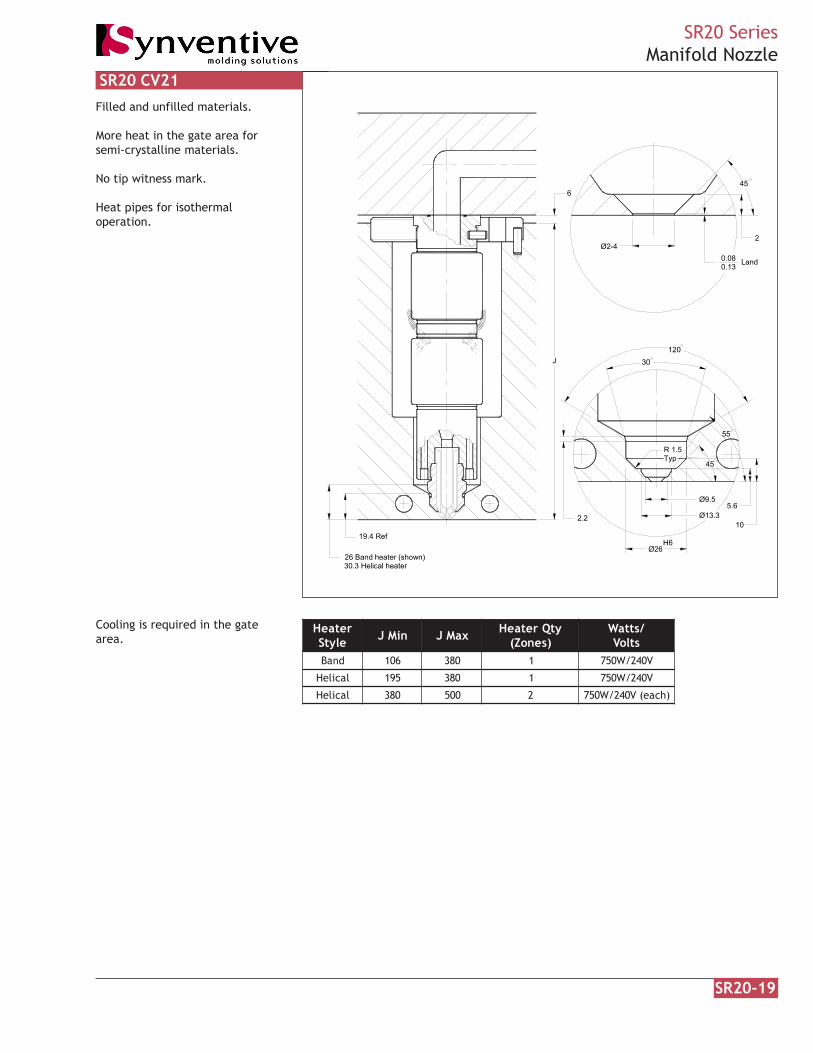
Filled and unfilled materials.
More heat in the gate area forsemi-crystalline materials.
No tip witness mark.
Heat pipes for isothermaloperation.
Cooling is required in the gatearea.
SR20 CV21
retaeHelytS niMJ xaMJ ytQretaeH
)senoZ(/sttaW
stloVdnaB 601 083 1 V042/W057
lacileH 591 083 1 V042/W057
lacileH 083 005 2 )hcae(V042/W057

SR20-20
SR20 SeriesCV21 Recess
Conical RecessDimple Dia.
D2
Recessh
30
Ø14
OrificeØ14
0.130.08
Land
h Max = 4D = 14 + 3.5(h)
Recessed gates are used to reducethe vestige height above the partsurface or keep the vestige belowthe part surface.
Maintain 0.13 land when machininggate orifice.
Values in tables are for materialsnot having glass fibers. ConsultSynventive for vestige heightwhen using glass fillers.
DDimple Dia. Recess
h
2
Spherical Recess
R25d
0.13
d (flat)Orifice
0.08 Land
h Max = 4
sseceRlacinoC
ecifirO h D
0.2 39.0 3.71
5.2 90.1 8.71
0.3 62.1 4.81
5.3 34.1 0.91
0.4 95.1 6.91
sseceRlacirehpS.aiDecifirO h d D
02.2-00.2 00.1 54.2 02.41
04.2-02.2 60.1 56.2 46.41
06.2-04.2 21.1 58.2 60.51
08.2-06.2 81.1 50.3 74.51
00.3-08.2 62.1 52.3 99.51
02.3-00.3 23.1 54.3 83.61
04.3-02.3 04.1 56.3 78.61
06.3-04.3 64.1 58.3 52.71
08.3-06.3 25.1 50.4 16.71
00.4-08.3 06.1 52.4 70.81

SR20-21
SR20 SeriesCV21 Angled Mold Contour
L
2 1.3 Min
K
Angled Mold Contour 0.080.13Land
2L
Orifice Dia.L = 0.13 + K - TAN
2 COS
L = 0.132
9°; K= TANOrifice Dia. 1.3COS2
L = 0.13 + K - TANOrifice Dia.2
13°; K= 4.75TAN + - 2Orifice Dia. - 2 1.39 13°; K= 4.75TAN + + TAN - 2
When gating onto an angled moldcontour the vestige height may beincreased depending on the angle.
K is the increase in vestige heightrequired to maintain 1.3 minimumwall thickness.
SR20-22
SR20 SeriesManifold Nozzle
J
6
26 Band heater (shown)30.3 Helical heater
19.4 Ref
120
H6
2.2
Ø26
30
Ø13.310
55
Ø9.5
TypR 1.5
5.6
45
45
Land0.130.08
2Ø3-4
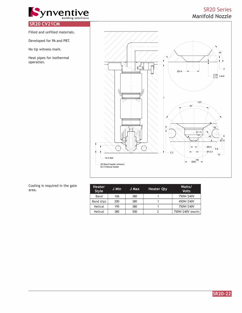
Filled and unfilled materials.
Developed for PA and PBT.
No tip witness mark.
Heat pipes for isothermaloperation.
Cooling is required in the gatearea.
SR20 CV21CM
retaeHelytS niMJ xaMJ ytQretaeH /sttaW
stloVdnaB 601 083 1 V042/W057
)pit(dnaB 002 083 1 V042/W054
lacileH 591 083 1 V042/W057
lacileH 083 005 2 )hcae(V042/W057
SR20-23
SR20 SeriesCV21CM Recess
Conical RecessDimple Dia.
D2
Recessh
30
Ø14
OrificeØ14
0.130.08
Land
h Max = 4D = 14 + 3.5(h)
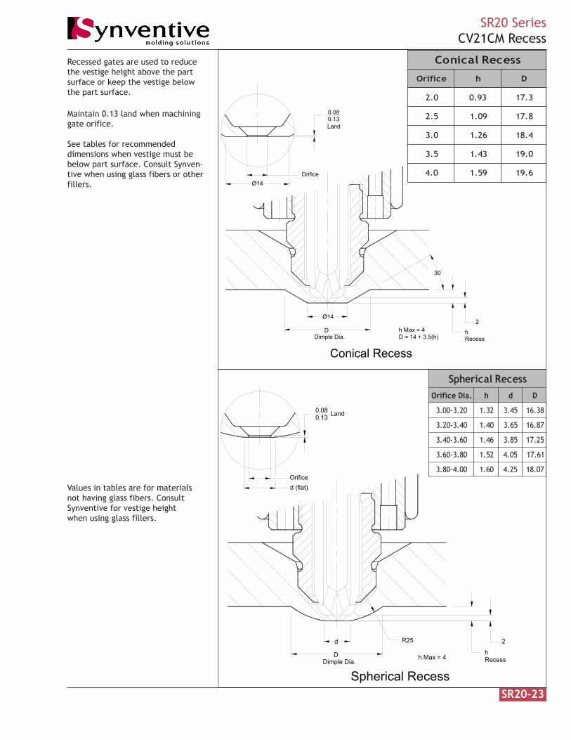
Maintain 0.13 land when machininggate orifice.
See tables for recommendeddimensions when vestige must bebelow part surface. Consult Synven-tive when using glass fibers or otherfillers.
Recessed gates are used to reducethe vestige height above the partsurface or keep the vestige belowthe part surface.
Values in tables are for materialsnot having glass fibers. ConsultSynventive for vestige heightwhen using glass fillers.
DDimple Dia. Recess
h
2
Spherical Recess
R25d
0.13
d (flat)Orifice
0.08 Land
h Max = 4
sseceRlacinoC
ecifirO h D
0.2 39.0 3.71
5.2 90.1 8.71
0.3 62.1 4.81
5.3 34.1 0.91
0.4 95.1 6.91
sseceRlacirehpS.aiDecifirO h d D
02.3-00.3 23.1 54.3 83.61
04.3-02.3 04.1 56.3 78.61
06.3-04.3 64.1 58.3 52.71
08.3-06.3 25.1 50.4 16.71
00.4-08.3 06.1 52.4 70.81
SR20-24
SR20 SeriesCV21CM Angled Mold Contour
L
2
K
LandL 2
0.130.08
1.3 Min
2 COS9°; K= TANOrifice Dia. 1.3COS2 13°; K= 4.75TAN + - 2Orifice Dia. - 2 1.3
L = 0.13 + K - TANL = 0.13 Orifice Dia.2
Orifice Dia.L = 0.13 + K - TAN2
Angled Mold Contour
9 13°; K= 4.75TAN + + TAN - 2
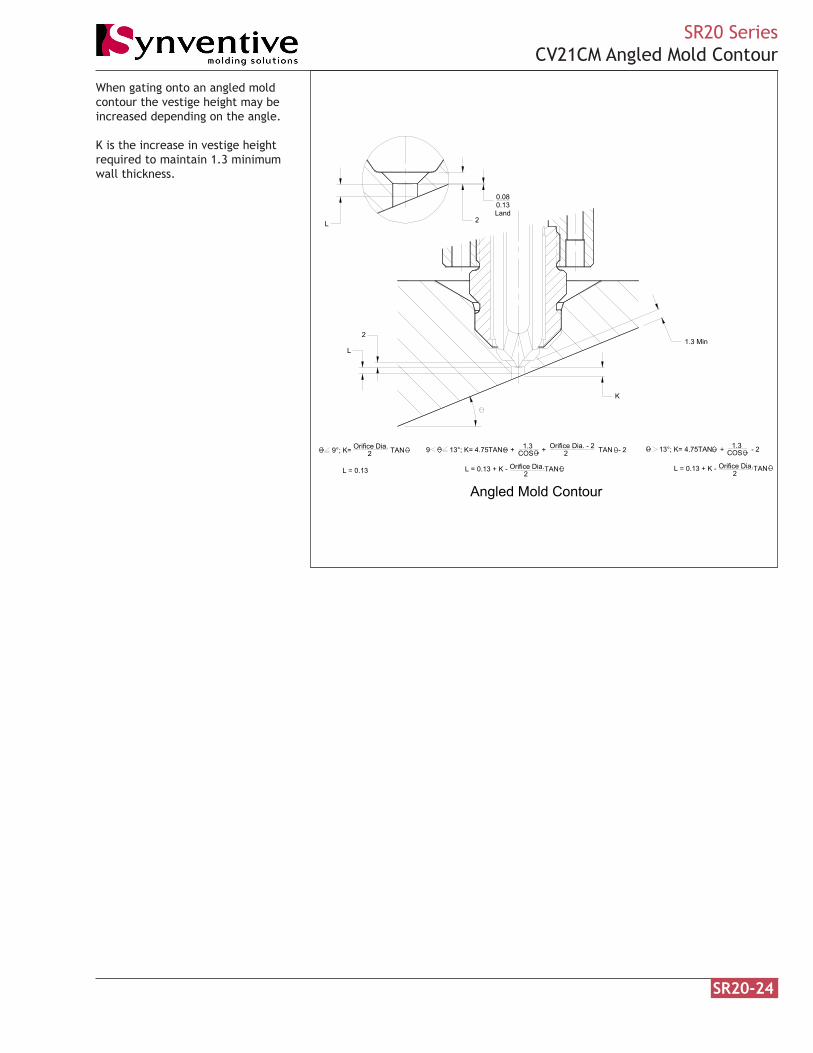
When gating onto an angled moldcontour the vestige height may beincreased depending on the angle.
K is the increase in vestige heightrequired to maintain 1.3 minimumwall thickness.
SR20-25
SR20 SeriesManifold Nozzle
120
Ø26H6
30
26 Band heater (shown)30.3 Helical heater
2.2
0.13Pin protrusion
15
Ø 3.9
6 Contact
Ø5
R0.132 Land
19.4 Ref
6
J
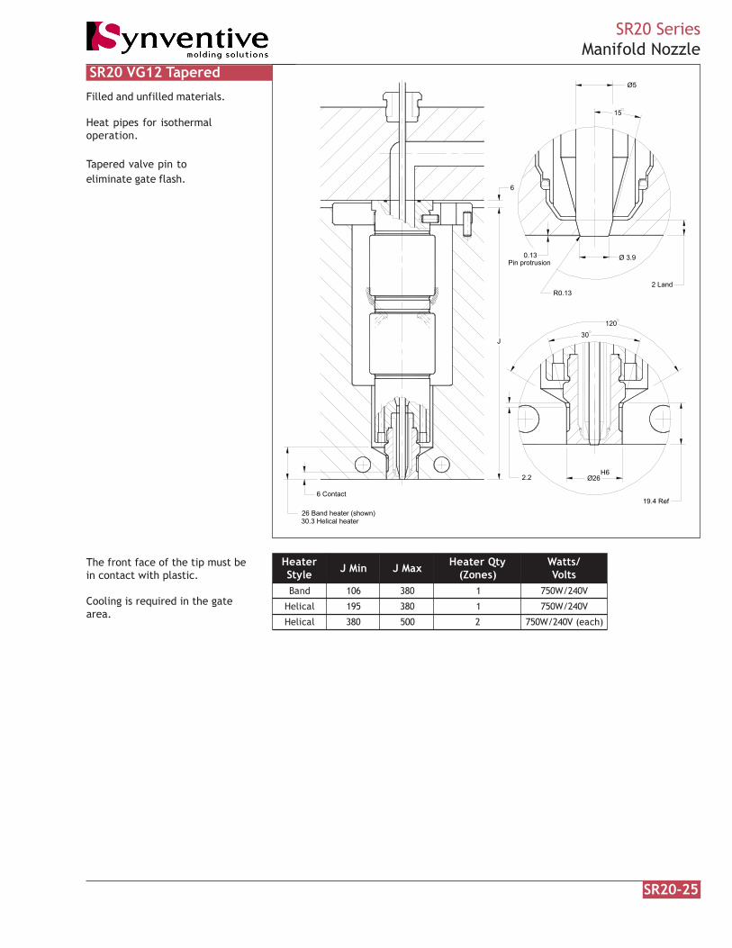
Filled and unfilled materials.
Heat pipes for isothermaloperation.
Tapered valve pin toeliminate gate flash.
The front face of the tip must bein contact with plastic.
Cooling is required in the gatearea.
SR20 VG12 Tapered
retaeHelytS niMJ xaMJ ytQretaeH
)senoZ(/sttaW
stloVdnaB 601 083 1 V042/W057
lacileH 591 083 1 V042/W057
lacileH 083 005 2 )hcae(V042/W057

SR20-26
SR20 SeriesVG12 Angled Mold Contour
Extension
K
2 1.3 Min
3 Mincontact
Land
R0.13 Ø3.9
15
Pin protrusion0.13
E = 13TAN
8°; K= 0
E = K + 13TAN
8°; K= 4.75TAN + -2COS1.3
Angled Mold Contour
When gating on an angled moldcontour the vestige height may beincreased depending on the angle.
K is the increase in land required tomaintain 1.3 minimum wall thick-ness.

SR20-27
SR20 SeriesManifold Nozzle
120
Ø26H6
30
26 Band heater (shown)30.3 Helical heater
2.2
0.13Pin protrusion
Ø 4.999
6 Contact
R0.13
2 Land
19.4 Ref
L
J
Ø 5.009
0.25 X 45
Filled and unfilled materials.
Heat pipes for isothermaloperation.
Straight valve pin in gate for non-adjustable actuators and glassfilled materials.
The front face of the tip must bein contact with plastic.
Cooling is required in the gatearea.
SR20 VG12S Straight
retaeHelytS niMJ xaMJ ytQretaeH
)senoZ(/sttaW
stloVdnaB 601 083 1 V042/W057
lacileH 591 083 1 V042/W057
lacileH 083 005 2 )hcae(V042/W057

SR20-28
SR20 SeriesVG12S Angled Mold Contour
Extension
K
2 1.3 Min
3 Mincontact
Land
R0.13 Ø5.009Ø4.999
Pin protrusion0.13
0.25 x 45
8°; K= 4.75TAN + -2
E = K + 13TAN
8°; K= 0
E = 13TAN
COS1.3
Angled Mold Contour
When gating on an angled moldcontour the vestige height may beincreased depending on the angle.
K is the increase in land required tomaintain 1.3 minimum wall thick-ness.

SR20-29
SR20 SeriesManifold Nozzle
120
Ø26H6
30
26 Band heater (shown)30.3 Helical heater
2.2
0.13Pin protrusion
15
Ø 3.9
90
35R1.5Typ
Ø13.3
Ø9.5
10
19.4 Ref
2 Land
5.6
Ø5
J
6
R0.13
Filled and unfilled materials.
No tip witness mark on part.
Heat pipes for isothermaloperation.
Tapered valve pin to eliminategate flash.
Cooling is required in the gatearea.
SR20 VG23 Tapered
retaeHelytS niMJ xaMJ ytQretaeH
)senoZ(/sttaW
stloVdnaB 601 083 1 V042/W057
lacileH 591 083 1 V042/W057
lacileH 083 005 2 )hcae(V042/W057
SR20-30
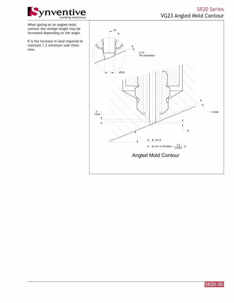
SR20 SeriesVG23 Angled Mold Contour
K
2 1.3 MinLand
Ø3.9
15
Pin protrusion0.13
8°; K= 4.75TAN + -2COS1.3
8°; K= 0
Angled Mold Contour
When gating on an angled moldcontour the vestige height may beincreased depending on the angle.
K is the increase in land required tomaintain 1.3 minimum wall thick-ness.
SR20-31
SR20 SeriesManifold Nozzle
120
Ø26H6
30
26 Band heater (shown)30.3 Helical heater
2.2
0.13Pin protrusion
Ø 5.009
90
35R1.5Typ
Ø13.3
Ø9.5
10
19.4 Ref
2 Land
5.6
Ø 4.999
R0.13
6
J
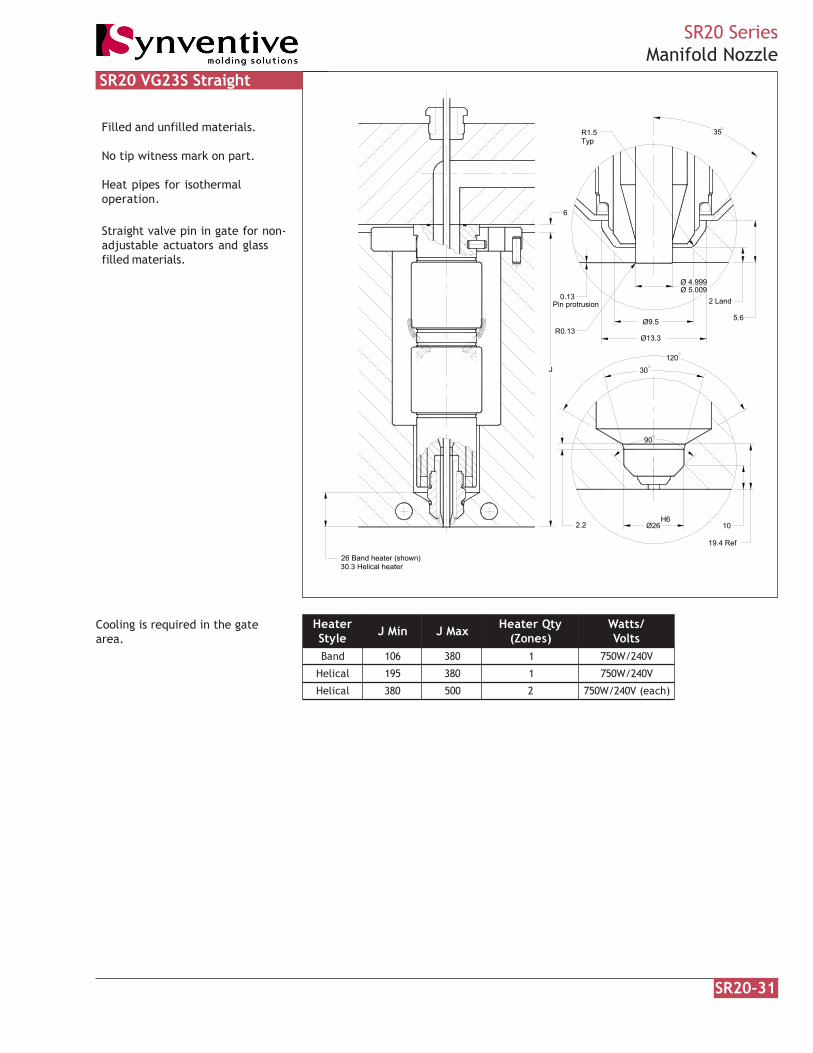
Filled and unfilled materials.
No tip witness mark on part.
Heat pipes for isothermaloperation.
Straight valve pin in gate for non-adjustable actuators and glassfilled materials.
Cooling is required in the gatearea.
SR20 VG23S Straight
retaeHelytS niMJ xaMJ ytQretaeH
)senoZ(/sttaW
stloVdnaB 601 083 1 V042/W057
lacileH 591 083 1 V042/W057
lacileH 083 005 2 )hcae(V042/W057
SR20-32
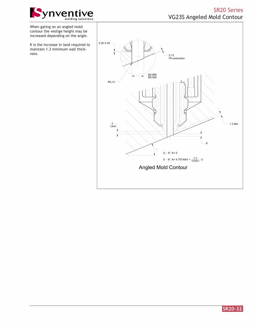
SR20 SeriesVG23S Angeled Mold Contour
K
2 1.3 MinLand
0.25 X 45
R0.13
Ø4.999Ø5.009
Pin protrusion0.13
8°; K= 0
8°; K= 4.75TAN + -2COS1.3
Angled Mold Contour
When gating on an angled moldcontour the vestige height may beincreased depending on the angle.
K is the increase in land required tomaintain 1.3 minimum wall thick-ness.


![Untitled-1 [] · GOLD PATCHES VESTIGE detox footpatches . Detox & Rejuvenation dietary . Plus Vestige Hoodia Plus Fitness + Diet VESTIGE slimming capsules Fitness + Diet VESTIGE protein](https://static.fdocuments.us/doc/165x107/5f4881605320ff26161a56ca/untitled-1-gold-patches-vestige-detox-footpatches-detox-rejuvenation.jpg)