SR Series Programmable Logic Controller - …maxthermo.com/ENG/upload/file/Catalog_SRPLC.pdf ·...
17
Copyright 2010-2011 © MAXTHERMO-GITTA GROUP CORPORATION SR Series Programmable Logic Controller Features 1. Real-time clock function 2. Password protection function 3. Removable panel and cost-saving 4. 30 kinds of function blocks, the total amount of function blocks reaches128 5. More compact, more powerful, flexible connection /EHC 6. Provide 64 Human-Machine Interfaces, and the parameters can be displayed and modified directly 7. I/O can be extended freely. The optimum configuration can be 50DI, 32DO, 8AI 8. UL/CE Approval 9. Support analog input 10. Support MODBUS RTU 11. Wireless remote control function 12. Furnished with simulation software 13. Provide one 1KHZ high-speed input port (this type needs to be customized) 14. Telephone remote control, automatic dialing alarm and voice broadcasting function 15. Retain the current data after a power failure and resume operation at the break point (this type needs to be customized
Transcript of SR Series Programmable Logic Controller - …maxthermo.com/ENG/upload/file/Catalog_SRPLC.pdf ·...

Copyright 2010-2011 © MAXTHERMO-GITTA GROUP CORPORATION
SR Series Programmable Logic Controller
Features
1. Real-time clock function
2. Password protection function
3. Removable panel and cost-saving
4. 30 kinds of function blocks, the total
amount of function blocks
reaches128
5. More compact, more powerful,
flexible connection /EHC
6. Provide 64 Human-Machine
Interfaces, and the parameters can
be displayed and modified directly
7. I/O can be extended freely. The
optimum configuration can be 50DI,
32DO, 8AI
8. UL/CE Approval
9. Support analog input
10. Support MODBUS RTU
11. Wireless remote control function
12. Furnished with simulation software
13. Provide one 1KHZ high-speed
input port (this type needs to be
customized)
14. Telephone remote control,
automatic dialing alarm and voice
broadcasting function
15. Retain the current data after a
power failure and resume operation
at the break point (this type needs
to be customized
Copyright 2010-2011 © MAXTHERMO-GITTA GROUP CORPORATION
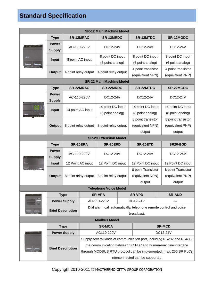
Standard Specification
SR-12 Main Machine Model
Type SR-12MRAC SR-12MRDC SR-12MTDC SR-12MGDC
Power
Supply AC-110-220V DC12-24V DC12-24V DC12-24V
Input 8 point AC input 8 point DC input
(6 point analog)
8 point DC input
(6 point analog)
8 point DC input
(6 point analog)
Output 4 point relay output 4 point relay output 4 point transistor
(equivalent NPN)
4 point transistor
(equivalent PNP)
SR-22 Main Machine Model
Type SR-22MRAC SR-22MRDC SR-22MTDC SR-22MGDC
Power
Supply AC-110-220V DC12-24V DC12-24V DC12-24V
Input 14 point AC input 14 point DC input
(8 point analog)
14 point DC input
(8 point analog)
14 point DC input
(8 point analog)
Output 8 point relay output 8 point relay output
8 point transistor
(equivalent NPN)
output
8 point transistor
(equivalent PNP)
output
SR-20 Extension Model
Type SR-20ERA SR-20ERD SR-20ETD SR20-EGD
Power
Supply AC-110-220V DC12-24V DC12-24V DC12-24V
Input 12 Point AC input 12 Point DC input 12 Point DC input 12 Point DC input
Output 8 point relay output 8 point relay output
8 point Transistor
(equivalent NPN)
output
8 point Transistor
(equivalent PNP)
output
Telephone Voice Model
Type SR-VPA SR-VPD SR-AUD
Power Supply AC-110-220V DC12-24V ---
Brief Description Dial alarm call automatically, telephone remote control and voice
broadcast.
Modbus Model
Type SR-MCA SR-MCD
Power Supply AC110-220V DC12-24V
Brief Description
Supply several kinds of communication port, including RS232 and RS485;
the communication between SR PLC and human-machine interface
through MODBUS RTU protocol can be implemented; max. 256 SR PLCs
interconnected can be supported.

Copyright 2010-2011 © MAXTHERMO-GITTA GROUP CORPORATION
Switching Power Supply
Type Output Voltage Output Current
MTP-0506AS DC5V 6A
MTP-1203AS DC12V 3A
MTP-2401AS DC24V 1.5A
MTP-0510AL DC12V 10A
MTP-1206AL DC12V 6A
MTP-2403AL DC12V 3A
MTP-48AS DC48V 0.75A
MTP-48AL DC48V 1.5A
Remote Control Model
Type SR-RCA SR-RCD
Power Supply AC110V-220V DC12-24V
Brief Description Remote receiving module provides 6 remote control input points.
SR-TC
Power Supply The transmitter uses two units of "AA" battery
Brief Description Remote receiver module provides 6 remote control input points.
SR-EANT
Power Supply ---
Brief Description SR-RCA/RCD lengthened connecting antenna.
SH-EHC SR-CP side-plug type /SR-DCP direct-plug type
Connection set of SR-HMI Remotely
connect SR main machine with
SR-HMI
The communication cable between
SR and PC, realizes the program,
analogue and slow monitor function
of the PC over SR.
SR-HMI/SR-WRT SR-DUSB/SR-DUSB
SR-HMI: Monitoring panel
SR-WRT: Programming Panel
The communication cable between
SR and PC USB

Copyright 2010-2011 © MAXTHERMO-GITTA GROUP CORPORATION
Common Specification
Type
Item
SR-12MRAC
SR-22MRAC
SR-20ERA
SR-12MRDC
SR-22MRDC
SR-20ERD
SR-12MTDC
SR-22MTDC
SR-20ETD
SR-12MGDC
SR-22MGDC
SR-20EGD
Power Supply
Rated Voltage AC100-240V DC12-24V DC12-24V DC12-24V
Allowable
Range AC85-260V DC10-28V DC10-28V DC10-28V
Input Section
Digital Input
8(A0~A5,B4~B5)/
14(A0~A7,B0~B5)/
12(X0~X7,Y0~Y3)
8(A0~A5,B4~B5)/
14(A0~A7,B0~B5)/
12(X0~X7,Y0~Y3)
8(A0~A5,B4~B5)/
14(A0~A7,B0~B5)/
12(X0~X7,Y0~Y3)
8(A0~A5,B4~B5)/
14(A0~A7,B0~B5)/
12(X0~X7,Y0~Y3)
Analog Input No 6(A0~A5)/
8(A0~A7)/No
6(A0~A5)/
8(A0~A7)/No
6(A0~A5)/
8(A0~A7)/No
Voltage for
Signal 0 AC0-40V DC0-5V DC0-5V DC0-5V
Voltage for
Signal 1 AC85-240V DC10-24V DC10-24V DC10-24V
Analog Voltage No DC0-10V/
DC0-10V/No
DC0-10V/
DC0-10V/No
DC0-10V/
DC0-10V/No
Delay Time for
0 to 1 50ms 50ms 50ms 50ms
Delay Time for
1 to 0 50ms 50ms 50ms 50ms
Output Section
Output Type Relay Relay Transistor (NPN) Transistor (PNP)
Output Current Resistor 10A
Induction 2A
Resistor 10A
Induction 2A ≤2A ≤2A
Switch Frequency
Mechanism 10Hz Resistance Load 2Hz Sensitive Load 0.5Hz
Environment Data
Operating
Temperature 0℃~55℃ Protection Type IP20 25℃ Clock Buffer 80h
Storage
Temperature -40℃~70℃
Interference
Regulation
EN55011
(B Class) RTC Accuracy Max ±5s/day
Transportation
Temperature -40℃~70℃
Insulation
Intensity IEC1131
Others
Clock buffer
memory at 25℃ 80h Emission on line EN55011(B) Function block No 128
RTC accuracy Max±5s/day The main
frequency range 47-63Hz
Program storage
capacity 64K
Protection IP20 Installation Use standard 35mm DIN rail or screw for installation

Copyright 2010-2011 © MAXTHERMO-GITTA GROUP CORPORATION
Telephone Voice Module
Index Standard
Automatically Receive CCITT-DTMF
Automatically Dial CCITT-DTMF
Broadcast Totally 100 messages
(Each message is limited to 15 seconds and the total time is about 8 minutes.)
Remote Receiving Module
Item Parameter
Power Consumption 1.5W
Operation Frequency VHF(310~340MHz) UHF(415~460MHz)
Remote control distance ≦70M
Remote Transmitter
Item Parameter
Power Consumption 40mW
Operation Frequency VHF(310~340MHz) UHF(415~460MHz)
Operation Voltage DC 3V (two units of AA)
Transmitting Power 3dbm

Copyright 2010-2011 © MAXTHERMO-GITTA GROUP CORPORATION
System Construct
SR System construct
MODBUS
(max. 256 SR PLCs interconnected can be supported.)
PC or HMI
HMI SR-HMI
Programming Panel SR-WRT
PC
or
PLC SR-22MRAC
Communication Cable
SR-CP
SR-CBA SR-CBA
Extension Model SR-22EMR
Voice Warning Telephone
Remote Control
Telephone Voice Model SR-VPA
Modbus Model SR-VPA
SR-CBA SR-CBA
Remote Control Model SR-RCA
Remote Controller SR-TC
Lengthened Connecting Antenna
SR-REANT
Copyright 2010-2011 © MAXTHERMO-GITTA GROUP CORPORATION
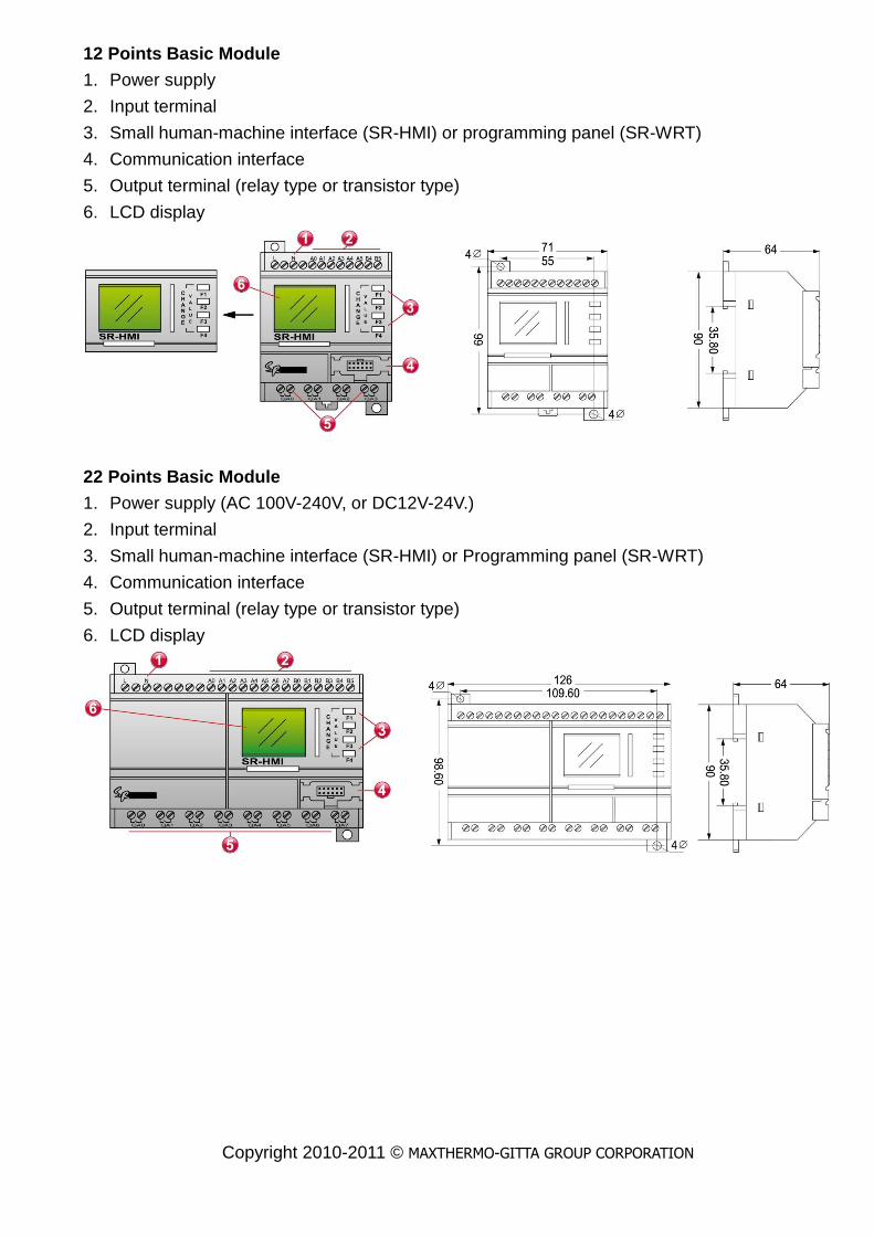
12 Points Basic Module
1. Power supply
2. Input terminal
3. Small human-machine interface (SR-HMI) or programming panel (SR-WRT)
4. Communication interface
5. Output terminal (relay type or transistor type)
6. LCD display
6.LCD 顯示幕
22 Points Basic Module
1. Power supply (AC 100V-240V, or DC12V-24V.)
2. Input terminal
3. Small human-machine interface (SR-HMI) or Programming panel (SR-WRT)
4. Communication interface
5. Output terminal (relay type or transistor type)
6. LCD display
Copyright 2010-2011 © MAXTHERMO-GITTA GROUP CORPORATION
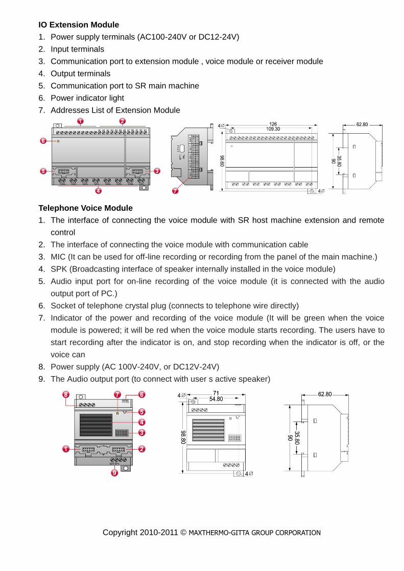
IO Extension Module
1. Power supply terminals (AC100-240V or DC12-24V)
2. Input terminals
3. Communication port to extension module , voice module or receiver module
4. Output terminals
5. Communication port to SR main machine
6. Power indicator light
7. Addresses List of Extension Module
Telephone Voice Module
1. The interface of connecting the voice module with SR host machine extension and remote
control
2. The interface of connecting the voice module with communication cable
3. MIC (It can be used for off-line recording or recording from the panel of the main machine.)
4. SPK (Broadcasting interface of speaker internally installed in the voice module)
5. Audio input port for on-line recording of the voice module (it is connected with the audio
output port of PC.)
6. Socket of telephone crystal plug (connects to telephone wire directly)
7. Indicator of the power and recording of the voice module (It will be green when the voice
module is powered; it will be red when the voice module starts recording. The users have to
start recording after the indicator is on, and stop recording when the indicator is off, or the
voice can
8. Power supply (AC 100V-240V, or DC12V-24V)
9. The Audio output port (to connect with user s active speaker)

Copyright 2010-2011 © MAXTHERMO-GITTA GROUP CORPORATION
Remote Control Module
1. The interface of connecting with host machine (main machine/voice/extension)
2. The interface of communicating with PC or next subordinate machine
3. The antenna of remote receiver
4. Power supply of remote control module (AC 110V/AC 220V, or DC12V-24V)
5. Power indicator
6. SR-TC transmitter
In different situations,
SR-TC indicator turns red
and green respectively

Copyright 2010-2011 © MAXTHERMO-GITTA GROUP CORPORATION
Installation Method
SR Software and Function
The simple Super CAD software provides a user-friendly operation interface. It can easily edit
function diagram through choosing and pulling relevant function and connection, and can
transform and examine the program on PC through the off-line simulation function. There are
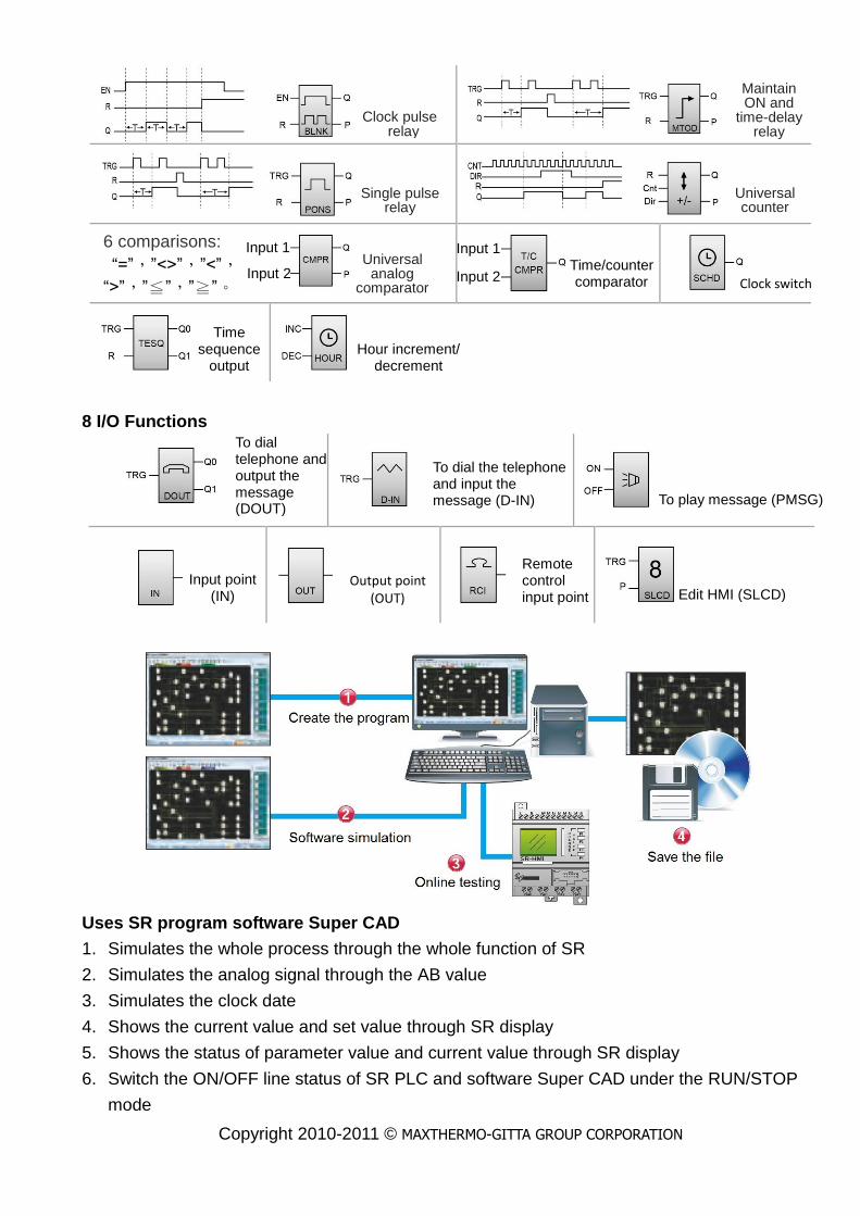
8 basic function blocks, 14 special function blocks, 8 I/O points and voice function blocks.
Every function block can implements the specific control function independently. When
several function blocks are linked together in a specific way, the complicated program can be
created quickly and easily.
8 Basic Functions
14 Special Functions
AND OR
NAND AND
AND NOR
XOR NOT
Time-delay ON
Time-delay OFF
Pulse relay RS relay
Copyright 2010-2011 © MAXTHERMO-GITTA GROUP CORPORATION
8 I/O Functions
Uses SR program software Super CAD
1. Simulates the whole process through the whole function of SR
2. Simulates the analog signal through the AB value
3. Simulates the clock date
4. Shows the current value and set value through SR display
5. Shows the status of parameter value and current value through SR display
6. Switch the ON/OFF line status of SR PLC and software Super CAD under the RUN/STOP
mode
Clock pulse relay
Maintain ON and
time-delay relay
Single pulse relay
Universal counter
6 comparisons:
“=”,”<>”,”<”,
“>”,”≦”,”≧”。
Universal analog
comparator
Input 1 Time/counter comparator Clock switch
Time sequence
output Hour increment/
decrement
To dial telephone and output the message (DOUT)
Input point (IN)
Output point (OUT)
Remote control input point
To dial the telephone and input the message (D-IN) To play message (PMSG)
Edit HMI (SLCD)
Input 2 Input 2
Input 1

Copyright 2010-2011 © MAXTHERMO-GITTA GROUP CORPORATION
Hardware Connections
Connect to the power supply
Input Connections
Digital input connections (AC type)
AC Type
DC Type
Wiring diagram Wiring diagram
Equivalent diagram
Wiring diagram
Equivalent diagram
AC Power Supply DC Type
Wiring diagram
Copyright 2010-2011 © MAXTHERMO-GITTA GROUP CORPORATION
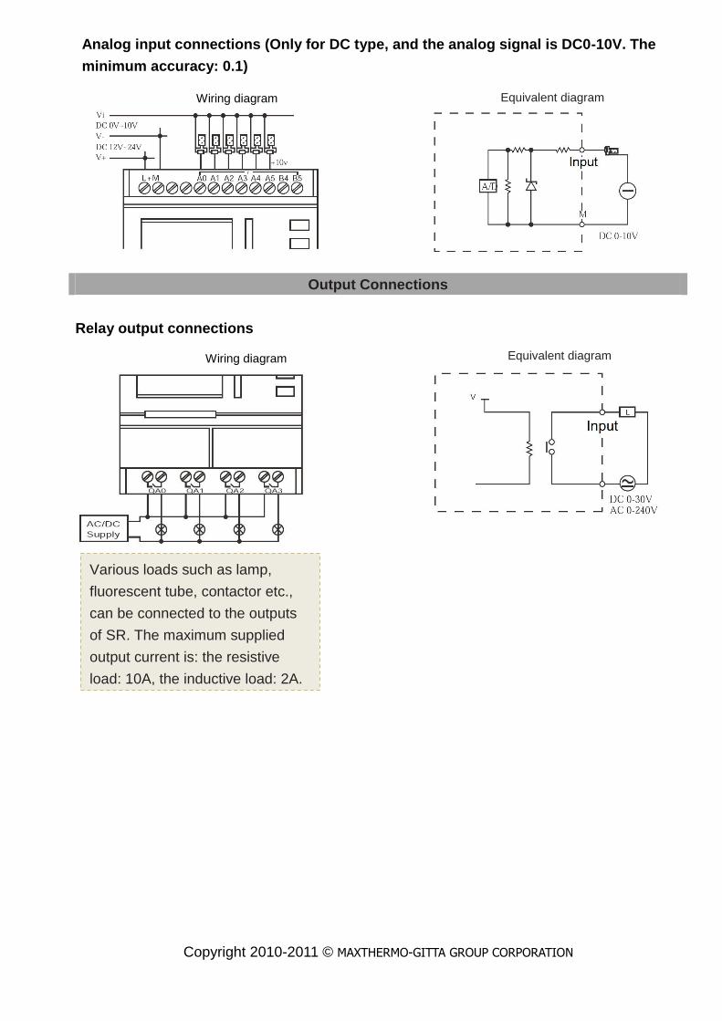
Analog input connections (Only for DC type, and the analog signal is DC0-10V. The
minimum accuracy: 0.1)
Output Connections
Relay output connections
Wiring diagram
Various loads such as lamp,
fluorescent tube, contactor etc.,
can be connected to the outputs
of SR. The maximum supplied
output current is: the resistive
load: 10A, the inductive load: 2A.
Equivalent diagram
Equivalent diagram
Wiring diagram

Copyright 2010-2011 © MAXTHERMO-GITTA GROUP CORPORATION
Transistor output connections
The transistor load connected with SR must have the following property: The maximum
switching current should not exceed 2A; The transistor load includes two types: NPN
and PNP.
NPN type transistor output
PNP type transistor output
Equivalent diagram
※The DC negative pole “-” of the load
should be connected to “M” of SR
power supply, and the load must be
connected to the positive pole“+”of DC
power supply
※The voltage of the load should not be
more than DC80V
Equivalent diagram
※The DC positive pole “+”of the load
should be connected to “L+” of SR
power supply, and the load must be
connected to the negative pole“-”of DC
power supply.
※The voltage of the load should not be
more than DC80V

Copyright 2010-2011 © MAXTHERMO-GITTA GROUP CORPORATION
Application Examples
Auto-door control Kinds of auto illumination
Alarming and signal bell system control Fountain system
Guard against theft and alarm system Plant watering
Bent-machine control Monitor system control
Selection the speed by the intelligent pin
button Packing system
Displaying window Control of the parking lots
Automation lighting control of the tunnel Machine tool automation
Water disposal automation Boiler automation
Street lamp control Warming & ventilation system control
Neon light control Electronic bell control in factories and schools
Persian blinds device control Puddles control system
Dip-dye, heat and transmission control of
textile Lift control
Order control over the cable soling machine Dynamo electric automation control
Agriculture irrigation automation control Step walking switch control
Automation control of the washing machine Refrigeration control of the refrigerator
Measure control of the liquid level Air conditioner system control
Application program examples:
Irrigation of Greenhouse Plants
Watering for plant 1
The water level is always kept in the set range via the float
switches for maximum and minimum value (IA0 and IA1);
Watering for plant 2
Via the time switch, the watering system is switched on for
4 minutes fromAM5:30 to AM5:34 and from PM8:30 to
PM8:34.
Watering for plant 3
Via the function of Current Impulse Relay, this plant is
watered for 2 minutes every other evening when the
photosensitive switch (IA2) responds.
Advantages and Specialties
The watering time can be
changed in the morning and
evening by your
desired.
The lighting and ventilation in
the greenhouse can also be
controlled by using of SR in
addition to watering plants.

Copyright 2010-2011 © MAXTHERMO-GITTA GROUP CORPORATION
Control system of shutter
The shutter can be manually controlled via the switches IA1
and IA2,in case that the selector switch (IA5) is not set at
automatic position.
Automatic operation:
The selector switch (IA5) must be set at automatic position
for automatic operation. If the photosensitive switch (IA0) is
activated, the shutter is closed in the period time from 6:00
in the evening to 7:00 in the next morning, and opened in
the period time from 7:00 in the morning to 6:00in the
evening.
Advantages and Specialties
The times can easily be
adjusted by any case, e.g.
different times on workdays,
weekend and holidays.
Energy saving by using of time
switch and photosensitive
switch.

Copyright 2010-2011 © MAXTHERMO-GITTA GROUP CORPORATION
Contact
Add: 3C25, Taipei World Trade Center, No. 5, Sec. 5, Hsin Yi Rd. Taipei Taiwan, R.O.C.
Tel: 886-2-27206601 (Rep.)
Fax: 886-2-23455120
E-mail: [email protected]
http://www.maxthermo.com
Add: 11F., No.168, Jiankang Rd., Zhonghe Dist, New Taipei City 235, Taiwan (R.O.C.)
Tel: 886-2-22287950 (Rep.)
Fax: 886-2-22286140
Add: 86/132-133 m.7 Samaedum Bangkoontien Bangkok 10150 Thailand.
Tel: +662-415-8318 , +662-417-2548-49
Fax: +662-415-8798
http://www.thaimaximum.com