SpW-10X SpaceWire Router User Manualaerosupport.atmel.com/Atmel/uod_spw_10x_usermanual_3_4.pdf ·...
157
SpW-10X SpaceWire Router User Manual Ref.: UoD_SpW-10X_ UserManual Issue: 3.5 Date: 7 th January 2015 1 SpW-10X SpaceWire Router User Manual Ref: UoD_SpW-10X_UserManual Atmel Part No.: AT7910E Document Revision: Issue 3.5 Date: 7 th January 2015 Prepared by - Chris McClements, University of Dundee Steve Parkes, University of Dundee Gerald Kempf, Austrian Aerospace Checked by - Steve Parkes, University of Dundee ESA Manager - Pierre Fabry, ESTEC
Transcript of SpW-10X SpaceWire Router User Manualaerosupport.atmel.com/Atmel/uod_spw_10x_usermanual_3_4.pdf ·...
SpW-10X
SpaceWire Router
User Manual
Ref.: UoD_SpW-10X_
UserManual
Issue: 3.5
Date: 7th January 2015
1
SpW-10X SpaceWire Router
User Manual
Ref: UoD_SpW-10X_UserManual
Atmel Part No.: AT7910E
Document Revision: Issue 3.5
Date: 7th January 2015
Prepared by - Chris McClements, University of Dundee
Steve Parkes, University of Dundee
Gerald Kempf, Austrian Aerospace
Checked by - Steve Parkes, University of Dundee
ESA Manager - Pierre Fabry, ESTEC
SpW-10X
SpaceWire Router
User Manual
Ref.: UoD_SpW-10X_
UserManual
Issue: 3.5
Date: 7th January 2015
2
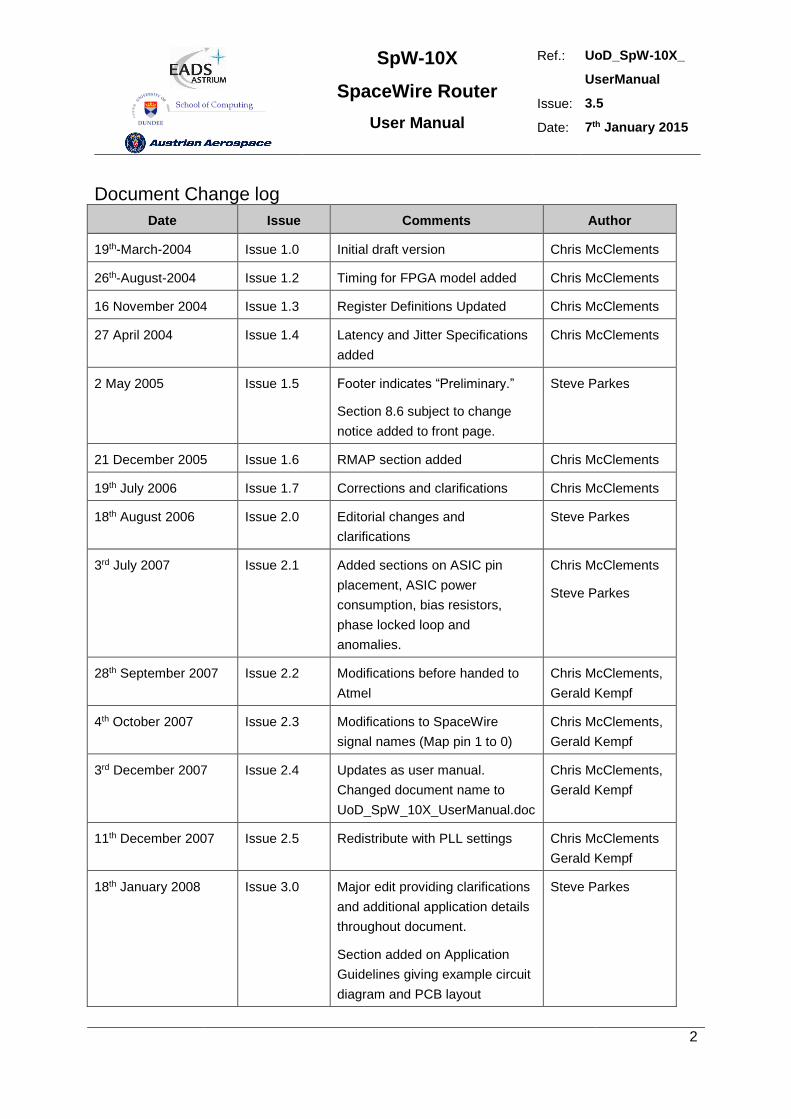
Document Change log
Date Issue Comments Author
19th-March-2004 Issue 1.0 Initial draft version Chris McClements
26th-August-2004 Issue 1.2 Timing for FPGA model added Chris McClements
16 November 2004 Issue 1.3 Register Definitions Updated Chris McClements
27 April 2004 Issue 1.4 Latency and Jitter Specifications
added
Chris McClements
2 May 2005 Issue 1.5 Footer indicates “Preliminary.”
Section 8.6 subject to change
notice added to front page.
Steve Parkes
21 December 2005 Issue 1.6 RMAP section added Chris McClements
19th July 2006 Issue 1.7 Corrections and clarifications Chris McClements
18th August 2006 Issue 2.0 Editorial changes and
clarifications
Steve Parkes
3rd July 2007 Issue 2.1 Added sections on ASIC pin
placement, ASIC power
consumption, bias resistors,
phase locked loop and
anomalies.
Chris McClements
Steve Parkes
28th September 2007 Issue 2.2 Modifications before handed to
Atmel
Chris McClements,
Gerald Kempf
4th October 2007 Issue 2.3 Modifications to SpaceWire
signal names (Map pin 1 to 0)
Chris McClements,
Gerald Kempf
3rd December 2007 Issue 2.4 Updates as user manual.
Changed document name to
UoD_SpW_10X_UserManual.doc
Chris McClements,
Gerald Kempf
11th December 2007 Issue 2.5 Redistribute with PLL settings Chris McClements
Gerald Kempf
18th January 2008 Issue 3.0 Major edit providing clarifications
and additional application details
throughout document.
Section added on Application
Guidelines giving example circuit
diagram and PCB layout
Steve Parkes
SpW-10X
SpaceWire Router
User Manual
Ref.: UoD_SpW-10X_
UserManual
Issue: 3.5
Date: 7th January 2015
3
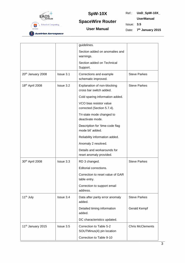
guidelines.
Section added on anomalies and
warnings.
Section added on Technical
Support.
20th January 2008 Issue 3.1 Corrections and example
schematic improved.
Steve Parkes
18th April 2008 Issue 3.2 Explanation of non-blocking
cross bar switch added.
Cold sparing information added.
VCO bias resistor value
corrected (Section 5.7.4).
Tri-state mode changed to
deactivate mode.
Description for ‘time-code flag
mode bit’ added.
Reliability information added.
Anomaly 2 resolved.
Details and workarounds for
reset anomaly provided.
Steve Parkes
30th April 2008 Issue 3.3 RD 3 changed.
Editorial corrections.
Correction to reset value of GAR
table entry.
Correction to support email
address.
Steve Parkes
11th July Issue 3.4 Data after parity error anomaly
added.
Steve Parkes
Detailed timing information
added.
DC characteristics updated.
Gerald Kempf
11th January 2015 Issue 3.5 Correction to Table 5-2
SOUTMinus(4) pin location
Correction to Table 9-10
Chris McClements
SpW-10X
SpaceWire Router
User Manual
Ref.: UoD_SpW-10X_
UserManual
Issue: 3.5
Date: 7th January 2015
4
POR_SEL_TIMEOUT_N reset
value polarity.
Correction to Table 10-1, TBC
removed.
SpW-10X
SpaceWire Router
User Manual
Ref.: UoD_SpW-10X_
UserManual
Issue: 3.5
Date: 7th January 2015
5
CONTENTS
CONTENTS ........................................................................................................................................ 5
I LIST OF FIGURES ...................................................................................................................... 11
II LIST OF TABLES ....................................................................................................................... 13
1. INTRODUCTION ........................................................................................................................ 15
1.1 TERMS, ACRONYMS AND ABBREVIATIONS ......................................................................... 15
1.2 DOCUMENTS .......................................................................................................................... 16
2. USER APPLICATIONS .............................................................................................................. 18
2.1 STAND-ALONE ROUTER ........................................................................................................ 18
2.2 NODE INTERFACE .................................................................................................................. 19
2.3 EMBEDDED ROUTER ............................................................................................................. 19
2.4 EXPANDING THE NUMBER OF ROUTER PORTS .................................................................. 20
3. FUNCTIONAL OVERVIEW ........................................................................................................ 23
3.1 SPACEWIRE PORTS............................................................................................................... 24
3.2 EXTERNAL PORTS ................................................................................................................. 24
3.3 CONFIGURATION PORT......................................................................................................... 25
3.4 ROUTING TABLE .................................................................................................................... 25
3.5 ROUTING CONTROL LOGIC AND CROSSBAR ...................................................................... 25
3.6 TIME-CODE PROCESSING ..................................................................................................... 26
3.7 CONTROL/STATUS REGISTERS ............................................................................................ 26
4. PIN LOCATIONS ....................................................................................................................... 27
5. DEVICE INTERFACE ................................................................................................................ 33
5.1 GLOBAL SIGNALS .................................................................................................................. 33
5.2 SPACEWIRE SIGNALS ........................................................................................................... 34
5.2.1 SpW-10X SpaceWire Signals ................................................................................................ 34
5.2.2 SpaceWire Input Fail Safe Resistors ...................................................................................... 37
5.2.3 Operation with 5V Powered LVDS Devices ............................................................................ 39
SpW-10X
SpaceWire Router
User Manual
Ref.: UoD_SpW-10X_
UserManual
Issue: 3.5
Date: 7th January 2015
6
5.3 EXTERNAL PORT DATA SIGNALS ......................................................................................... 39
5.4 TIME-CODE SIGNALS ............................................................................................................. 41
5.5 STATUS INTERFACE SIGNALS .............................................................................................. 43
5.6 RESET CONFIGURATION SIGNALS ....................................................................................... 44
5.7 POWER, GROUND, PLL AND LVDS SIGNALS ....................................................................... 47
5.7.1 General ................................................................................................................................. 47
5.7.2 Decoupling ............................................................................................................................ 47
5.7.3 LVDS Reference ................................................................................................................... 47
5.7.4 PLL External Components ..................................................................................................... 47
6. INTERFACE OPERATIONS ...................................................................................................... 49
6.1 EXTERNAL PORT INTERFACE OPERATION ......................................................................... 49
6.2 TIME-CODE INTERFACE OPERATION ................................................................................... 50
6.3 STATUS INTERFACE OPERATION......................................................................................... 51
6.4 RESET CONFIGURATION INTERFACE OPERATION ............................................................. 53
7. SPACEWIRE ROUTER PACKET TYPES .................................................................................. 54
7.1 PACKET ADDRESSES ............................................................................................................ 54
7.2 PACKET PRIORITY ................................................................................................................. 55
7.3 PACKET HEADER DELETION ................................................................................................. 55
7.4 INVALID ADDRESSES ............................................................................................................ 56
7.5 DATA PACKETS ...................................................................................................................... 57
7.6 COMMAND PACKETS ............................................................................................................. 57
7.6.1 Supported Commands ........................................................................................................... 57
7.6.2 Read Command .................................................................................................................... 58
7.6.3 Read Incrementing Command ............................................................................................... 62
7.6.4 Read Modify Write Command ................................................................................................ 67
7.6.5 Write Command .................................................................................................................... 72
7.6.6 Command Error Response .................................................................................................... 76
7.6.7 Command Packet Cyclic Redundancy Check ........................................................................ 78
7.6.8 Local Source Path Address ................................................................................................... 78
7.6.9 Source Path Address Field .................................................................................................... 78
7.6.10 Command Packet Fill Bytes ................................................................................................. 80
8. CONTROL LOGIC AND OPERATIONAL MODES ..................................................................... 81
8.1 SPACEWIRE LINK CONTROL ................................................................................................. 81
8.1.1 Default operating mode ......................................................................................................... 81
SpW-10X
SpaceWire Router
User Manual
Ref.: UoD_SpW-10X_
UserManual
Issue: 3.5
Date: 7th January 2015
7
8.1.2 Auto-Start .............................................................................................................................. 81
8.1.3 Link-Start .............................................................................................................................. 81
8.1.4 Link-Disable .......................................................................................................................... 82
8.1.5 Automatic deactivate driver mode .......................................................................................... 82
8.1.6 Setting the SpaceWire port transmit data rate ........................................................................ 84
8.2 GLOBAL SPACEWIRE LINK CONTROL .................................................................................. 87
8.2.1 Start on request mode ........................................................................................................... 87
8.2.2 Disable on Silence mode ....................................................................................................... 87
8.3 CONTROL LOGIC AND ROUTING .......................................................................................... 88
8.3.1 Packet address error ............................................................................................................. 88
8.3.2 Arbitration.............................................................................................................................. 88
8.3.2.1 Arbitration of packets with matching priority (1) ................................................................... 89
8.3.2.2 Arbitration of packets with matching priority (2) ................................................................... 90
8.3.2.3 Arbitration of packets with different priority (1) ..................................................................... 91
8.3.2.4 Arbitration of packets with different priority (2) ..................................................................... 92
8.3.3 Group Adaptive Routing ........................................................................................................ 94
8.3.3.1 Normal Group adaptive routing ........................................................................................... 94
8.3.3.2 Group adaptive routing when busy...................................................................................... 94
8.3.3.3 Group adaptive routing when ports not ready ...................................................................... 95
8.3.4 Loop-back with Self-Addressing............................................................................................. 95
8.3.5 Packet Blocking ..................................................................................................................... 97
8.3.5.1 Blocked destination ............................................................................................................ 97
8.3.5.2 Stalled source .................................................................................................................. 100
8.3.5.3 Waiting for an output port ................................................................................................. 103
9. REGISTER DEFINITIONS ....................................................................................................... 105
9.1 INTERNAL MEMORY MAP .................................................................................................... 105
9.2 REGISTER ADDRESSES SUMMARY ................................................................................... 106
9.3 GROUP ADAPTIVE ROUTING TABLE REGISTERS ............................................................. 107
9.4 PORT CONTROL/STATUS REGISTERS ............................................................................... 110
9.4.1 Generic port control/status register fields. ............................................................................ 110
9.4.2 Configuration port control/status register fields..................................................................... 111
9.4.3 SpaceWire port control/status register bits. .......................................................................... 114
9.4.4 External port control/status register bits. .............................................................................. 117
9.5 ROUTER CONTROL/STATUS REGISTERS .......................................................................... 117
9.5.1 Network Discovery Register................................................................................................. 117
9.5.2 Router Identity Register ....................................................................................................... 118
9.5.3 Router Control Register ....................................................................................................... 119
9.5.4 Error active Register ............................................................................................................ 122
SpW-10X
SpaceWire Router
User Manual
Ref.: UoD_SpW-10X_
UserManual
Issue: 3.5
Date: 7th January 2015
8
9.5.5 Time-Code Register ............................................................................................................ 123
9.5.6 Device Manufacturer and Chip ID Register .......................................................................... 124
9.5.7 General Purpose Register ................................................................................................... 125
9.5.8 Time-Code Enable Register ................................................................................................ 125
9.5.9 Transmit Clock Control Register .......................................................................................... 126
9.5.10 Destination Key Register ................................................................................................... 129
9.5.11 Unused Registers and Register Bits .................................................................................. 129
9.5.12 Empty packets ................................................................................................................... 129
9.6 WRITING TO A READ-ONLY REGISTER .............................................................................. 129
10. SWITCHING CHARACTERISTICS ........................................................................................ 130
10.1 CLOCK AND RESET TIMING PARAMETERS...................................................................... 130
10.2 SERIAL SIGNALS TIMING PARAMETERS .......................................................................... 130
10.3 EXTERNAL PORT TIMING PARAMETERS ......................................................................... 131
10.4 TIME-CODE INTERFACE TIMING PARAMETERS .............................................................. 132
10.5 ERROR/STATUS INTERFACE TIMING PARAMETERS ...................................................... 134
10.6 LATENCY AND JITTER ....................................................................................................... 135
10.6.1 Clock Periods .................................................................................................................... 135
10.6.2 Switching Latency ............................................................................................................. 135
10.6.3 Router Latency .................................................................................................................. 135
10.6.4 Time-code Latency ............................................................................................................ 136
10.6.5 Time-code Jitter ................................................................................................................. 137
10.6.6 200M bits/s Input and Output Bit Rate Example ................................................................. 137
11. ELECTRICAL CHARACTERISTICS ...................................................................................... 138
11.1 DC CHARACTERISTICS...................................................................................................... 138
11.2 ABSOLUTE MAXIMUM RATINGS ........................................................................................ 139
11.3 RELIABILITY INFORMATION .............................................................................................. 139
12. APPLICATION GUIDELINES ................................................................................................. 140
12.1 EXAMPLE CIRCUIT DIAGRAM ............................................................................................ 140
12.2 PCB DESIGN AND LAYOUT GUIDELINES .......................................................................... 142
12.2.1 CLK ................................................................................................................................... 142
12.2.2 RST_N .............................................................................................................................. 142
12.2.3 Chip Test Signals .............................................................................................................. 142
12.2.4 Power and Decoupling ...................................................................................................... 142
12.2.5 Ground .............................................................................................................................. 142
12.2.6 SpaceWire ........................................................................................................................ 142
SpW-10X
SpaceWire Router
User Manual
Ref.: UoD_SpW-10X_
UserManual
Issue: 3.5
Date: 7th January 2015
9
12.2.7 External Ports .................................................................................................................... 143
12.2.8 Time-code Interface ........................................................................................................... 143
12.2.9 Status / Power On Configuration Interface ......................................................................... 143
12.2.10 PLL ................................................................................................................................. 144
13. ANOMALIES AND WARNINGS ............................................................................................. 145
13.1 ANOMALIES ........................................................................................................................ 145
13.2 WARNINGS ......................................................................................................................... 145
13.3 RESET ANOMALY ............................................................................................................... 147
13.3.1 Data Strobe Reset Waveform ............................................................................................ 147
13.3.2 Data Strobe Disable Waveform .......................................................................................... 149
13.3.3 Reset Anomaly Workarounds ............................................................................................ 149
13.4 PARITY ERROR ANOMALY ................................................................................................ 150
13.4.1 Parity Error Action ............................................................................................................. 150
13.4.2 Parity Error Anomaly ......................................................................................................... 150
13.4.3 Parity Error Workaround .................................................................................................... 151
14. TECHNICAL SUPPORT ........................................................................................................ 152
15. DOCUMENT CHANGES ........................................................................................................ 153
15.1 ISSUE 3.4 TO ISSUE 3.5 ..................................................................................................... 153
15.2 ISSUE 3.3 TO ISSUE 3.4 ..................................................................................................... 153
15.3 ISSUE 3.2 TO ISSUE 3.3 ..................................................................................................... 153
15.4 ISSUE 3.1 TO ISSUE 3.2 ..................................................................................................... 154
15.5 ISSUE 3.0 TO ISSUE 3.1 ..................................................................................................... 154
15.6 ISSUE 2.5 TO ISSUE 3.0 ..................................................................................................... 155
15.7 ISSUE 2.4 TO ISSUE 2.5 ..................................................................................................... 155
15.8 ISSUE 2.3 TO ISSUE 2.4 ..................................................................................................... 155
15.9 ISSUE 2.2 TO ISSUE 2.3 ..................................................................................................... 156
15.10 ISSUE 2.1 TO ISSUE 2.2 ................................................................................................... 156
15.11 ISSUE 2.0 TO ISSUE 2.1 ................................................................................................... 156
15.12 ISSUE 1.7 TO ISSUE 2.0 ................................................................................................... 156
15.13 ISSUE 1.6 TO ISSUE 1.7 ................................................................................................... 156
15.14 ISSUE 1.5 TO ISSUE 1.6 ................................................................................................... 156
15.15 ISSUE 1.4 TO ISSUE 1.5 ................................................................................................... 156
SpW-10X
SpaceWire Router
User Manual
Ref.: UoD_SpW-10X_
UserManual
Issue: 3.5
Date: 7th January 2015
10
15.16 ISSUE 1.3 TO ISSUE 1.4 ................................................................................................... 157
15.17 ISSUE 1.2 TO ISSUE 1.3 ................................................................................................... 157
15.18 ISSUE 1.1 TO ISSUE 1.2 ................................................................................................... 157
15.19 ISSUE 1.0 TO ISSUE 1.1 ................................................................................................... 157
SpW-10X
SpaceWire Router
User Manual
Ref.: UoD_SpW-10X_
UserManual
Issue: 3.5
Date: 7th January 2015
11
I LIST OF FIGURES
FIGURE 2-1 STAND-ALONE ROUTER ...................................................................................................................... 18
FIGURE 2-2 NODE INTERFACE ................................................................................................................................ 19
FIGURE 2-3 EMBEDDED ROUTER ........................................................................................................................... 20
FIGURE 2-4 EXPANDING THE NUMBER OF SPACEWIRE PORTS (1) .......................................................................... 21
FIGURE 2-5 EXPANDING THE NUMBER OF SPACEWIRE PORTS (2) .......................................................................... 22
FIGURE 3-1 SPACEWIRE ROUTER BLOCK DIAGRAM ............................................................................................... 24
FIGURE 5-1 LVDS RECEIVER FAIL-SAFE RESISTORS............................................................................................. 37
FIGURE 5-2 CONFIGURATION INTERFACE TIMING SPECIFICATION .......................................................................... 44
FIGURE 5-3 PLL WITH EXTERNAL COMPONENTS .................................................................................................... 48
FIGURE 6-1 EXTERNAL PORT WRITE TIMING SPECIFICATION .................................................................................. 49
FIGURE 6-2 EXTERNAL PORT READ TIMING SPECIFICATION ................................................................................... 50
FIGURE 6-3 TIME-CODE INPUT INTERFACE ............................................................................................................ 50
FIGURE 6-4 TIME-CODE OUTPUT INTERFACE ........................................................................................................ 51
FIGURE 6-5 TIME-CODE RESET INTERFACE ............................................................................................................. 51
FIGURE 6-6 STATUS MULTIPLEXER OUTPUT INTERFACE ........................................................................................ 51
FIGURE 6-7 RESET CONFIGURATION INTERFACE TIMING SPECIFICATION ................................................................ 53
FIGURE 7-1 NORMAL ROUTER DATA PACKETS ....................................................................................................... 57
FIGURE 7-2 COMMAND PACKET FORMAT .............................................................................................................. 57
FIGURE 7-3 READ SINGLE ADDRESS COMMAND FORMAT ..................................................................................... 59
FIGURE 7-4 READ SINGLE ADDRESS REPLY PACKET FORMAT ............................................................................... 61
FIGURE 7-5 READ INCREMENTING ADDRESS COMMAND FORMAT ......................................................................... 64
FIGURE 7-6 READ INCREMENTING ADDRESS REPLY PACKET FORMAT .................................................................. 66
FIGURE 7-7 READ-MODIFY-WRITE COMMAND PACKET FORMAT ......................................................................... 68
FIGURE 7-8 READ-MODIFY-WRITE EXAMPLE OPERATION ..................................................................................... 70
FIGURE 7-9 READ-MODIFY-WRITE REPLY PACKET FORMAT ................................................................................ 71
FIGURE 7-10 WRITE SINGLE ADDRESS COMMAND PACKET ................................................................................... 73
FIGURE 7-11 WRITE SINGLE ADDRESS REPLY PACKET ......................................................................................... 75
FIGURE 7-12 SOURCE PATH ADDRESS FIELD DECODING ........................................................................................ 80
FIGURE 7-13 SOURCE PATH ADDRESSES IN REPLY PACKET .................................................................................. 80
FIGURE 7-14 NORMAL CONFIGURATION PACKET HEADER STRUCTURE ................................................................ 80
FIGURE 7-15 FILL BYTES CONFIGURATION HEADER STRUCTURE .......................................................................... 80
FIGURE 8-1 DEACTIVATE DRIVER OPERATING MODE ............................................................................................. 83
FIGURE 8-2 DEACTIVATED LDVS DRIVER OUTPUT................................................................................................ 83
FIGURE 8-3 DEACTIVATED LDVS DRIVER OUTPUT CONNECTED TO EXTERNAL BIAS NETWORK ON LVDS INPUT .. 84
FIGURE 8-4 START ON REQUEST MODE .................................................................................................................. 87
FIGURE 8-5 DISABLE ON SILENCE MODE ................................................................................................................ 88
FIGURE 8-6 ARBITRATION OF TWO PACKETS WITH MATCHING PRIORITY. .............................................................. 89
FIGURE 8-7 ARBITRATION OF THREE PACKETS WITH MATCHING PRIORITY ............................................................ 90
SpW-10X
SpaceWire Router
User Manual
Ref.: UoD_SpW-10X_
UserManual
Issue: 3.5
Date: 7th January 2015
12
FIGURE 8-8 ARBITRATION OF TWO PACKETS WITH DIFFERENT PRIORITY (1) .......................................................... 91
FIGURE 8-9 ARBITRATION OF TWO PACKETS WITH DIFFERENT PRIORITY (2) .......................................................... 93
FIGURE 8-10 NORMAL GROUP ADAPTIVE ROUTING ................................................................................................ 94
FIGURE 8-11 GROUP ADAPTIVE ROUTING WHEN OTHER PORTS BUSY ..................................................................... 95
FIGURE 8-12 GROUP ADAPTIVE ROUTING WHEN PORTS NOT READY....................................................................... 95
FIGURE 8-13 PACKET SELF-ADDRESSING MODE .................................................................................................... 96
FIGURE 8-14 DESTINATION NODE BLOCKED (A) .................................................................................................... 98
FIGURE 8-15 DESTINATION NODE BLOCKED (B) .................................................................................................... 98
FIGURE 8-16 DESTINATION NODE BLOCKED (C) .................................................................................................... 99
FIGURE 8-17 DESTINATION NODE BLOCKED: WATCHDOG MODE (A) .................................................................... 99
FIGURE 8-18 DESTINATION NODE BLOCKED: WATCHDOG MODE (B) .................................................................... 99
FIGURE 8-19 DESTINATION NODE BLOCKED: WATCHDOG MODE (C) .................................................................. 100
FIGURE 8-20 DESTINATION NODE BLOCKED: WATCHDOG MODE (D) .................................................................. 100
FIGURE 8-21 SOURCE NODE STALLED (A) ........................................................................................................... 101
FIGURE 8-22 SOURCE NODE STALLED (B) ............................................................................................................ 101
FIGURE 8-23 SOURCE NODE STALLED (C) ............................................................................................................ 101
FIGURE 8-24 SOURCE NODE STALLED (D) ........................................................................................................... 101
FIGURE 8-25 SOURCE NODE STALLED: WATCHDOG MODE (A) ........................................................................... 102
FIGURE 8-26 SOURCE NODE STALLED: WATCHDOG MODE (B) ............................................................................ 102
FIGURE 8-27 SOURCE NODE STALLED: WATCHDOG MODE (C) ............................................................................ 102
FIGURE 8-28 SOURCE NODE STALLED: WATCHDOG MODE (D) ........................................................................... 102
FIGURE 9-1 ROUTER INTERNAL MEMORY MAP ................................................................................................... 105
FIGURE 9-2 GAR REGISTER FIELDS ..................................................................................................................... 107
FIGURE 9-3 SPACEWIRE PORT CONTROL/STATUS REGISTER FIELDS ................................................................... 114
FIGURE 9-4 NETWORK DISCOVERY REGISTER FIELDS ......................................................................................... 118
FIGURE 9-5 ROUTER CONTROL REGISTER FIELDS ................................................................................................ 119
FIGURE 9-6 ERROR ACTIVE REGISTER FIELDS ..................................................................................................... 122
FIGURE 9-7 TIME-CODE REGISTER FIELDS .......................................................................................................... 123
FIGURE 9-8 DEVICE MANUFACTURER AND CHIP ID REGISTER FIELDS ................................................................ 124
FIGURE 9-9 TIME-CODE ENABLE REGISTER FIELDS ............................................................................................. 125
FIGURE 9-10 TRANSMIT CLOCK CONTROL REGISTER ........................................................................................... 127
FIGURE 10-1 DS MINIMUM CONSECUTIVE EDGE SEPARATION .............................................................................. 130
FIGURE 10-2 EXTERNAL PORT INPUT FIFO TIMING PARAMETERS ........................................................................ 131
FIGURE 10-3 EXTERNAL PORT OUTPUT FIFO TIMING PARAMETERS ..................................................................... 131
FIGURE 10-4 TIME-CODE INPUT INTERFACE ........................................................................................................ 132
FIGURE 10-5 TIME-CODE OUTPUT INTERFACE .................................................................................................... 133
FIGURE 10-6 TIME-CODE TIME_CTR_RST INTERFACE ...................................................................................... 133
FIGURE 12-1 PLL LAYOUT RECOMMENDATIONS ................................................................................................. 144
FIGURE 13-1 RESET WAVEFORM ......................................................................................................................... 148
FIGURE 13-2 RESET WAVEFORM WITH DATA AND STROBE BOTH HIGH .............................................................. 148
FIGURE 13-3 GLITCHES ON DATA OR STROBE DURING RESET ............................................................................. 148
FIGURE 13-4 SIMULTANEOUS TRANSITION OF DATA AND STROBE DURING RESET .............................................. 148
SpW-10X
SpaceWire Router
User Manual
Ref.: UoD_SpW-10X_
UserManual
Issue: 3.5
Date: 7th January 2015
13
FIGURE 13-5 LINK DISCONNECT WAVEFORMS .................................................................................................... 149
FIGURE 13-6 DATA AFTER PARITY ERROR ANOMALY ........................................................................................... 150
FIGURE 13-7 NO ERROR END OF PACKET INSERTED AFTER PARITY ERROR ........................................................... 151
II LIST OF TABLES
TABLE 1-1 APPLICABLE DOCUMENTS .................................................................................................................... 16
TABLE 1-2 REFERENCE DOCUMENTS ..................................................................................................................... 17
TABLE 5-1 GLOBAL SIGNALS ................................................................................................................................. 34
TABLE 5-2 DATA AND STROBE SPACEWIRE SIGNALS ............................................................................................ 35
TABLE 5-3 EXTERNAL PORT INTERFACE SIGNALS ................................................................................................. 39
TABLE 5-4 TIME-CODE SIGNALS ........................................................................................................................... 41
TABLE 5-5 LINK ERROR INDICATION SIGNALS ....................................................................................................... 43
TABLE 5-6 RESET CONFIGURATION SIGNALS ........................................................................................................ 45
TABLE 5-7 POWER, GROUND AND SPECIAL SIGNALS ............................................................................................. 47
TABLE 6-1 MULTIPLEXED STATUS PINS BIT ASSIGNMENT .................................................................................... 52
TABLE 7-1 PACKET ADDRESS MAPPING ................................................................................................................ 54
TABLE 7-2 PACKET PRIORITY MAPPING ................................................................................................................ 55
TABLE 7-3 PACKET HEADER DELETION MAPPING ................................................................................................. 56
TABLE 7-4 SUPPORTED RMAP COMMAND CODES ................................................................................................ 58
TABLE 7-5 READ SINGLE ADDRESS CHARACTERISTICS ......................................................................................... 59
TABLE 7-6 READ SINGLE ADDRESS COMMAND PACKET FIELDS ........................................................................... 60
TABLE 7-7 READ SINGLE ADDRESS REPLY PACKET FIELDS .................................................................................. 61
TABLE 7-8 READ INCREMENTING ADDRESS CHARACTERISTICS ............................................................................ 63
TABLE 7-9 READ INCREMENTING ADDRESS COMMAND PACKET FIELDS ............................................................... 64
TABLE 7-10 READ INCREMENTING ADDRESS REPLY PACKET FIELDS .................................................................... 66
TABLE 7-11 READ-MODIFY-WRITE COMMAND CHARACTERISTICS ...................................................................... 67
TABLE 7-12 READ-MODIFY-WRITE COMMAND PACKET FIELDS ........................................................................... 69
TABLE 7-13 READ-MODIFY-WRITE REPLY PACKET FIELDS .................................................................................. 71
TABLE 7-14 WRITE COMMAND CHARACTERISTICS................................................................................................ 72
TABLE 7-15 WRITE SINGLE ADDRESS COMMAND PACKET FIELDS ........................................................................ 73
TABLE 7-16 WRITE SINGLE ADDRESS REPLY PACKET FIELDS ............................................................................... 75
TABLE 7-17 CONFIGURATION PORT ERRORS SUMMARY ........................................................................................ 76
TABLE 7-18 SOURCE PATH ADDRESS REFERENCE TABLE...................................................................................... 79
TABLE 8-1 SETTING SPACEWIRE TRANSMIT DATA RATE ...................................................................................... 85
TABLE 9-1 TYPES OF REGISTER WITHIN CONFIGURATION PORT .......................................................................... 106
TABLE 9-2 CONFIGURATION REGISTER ADDRESSES ............................................................................................ 107
TABLE 9-3 GAR TABLE REGISTER DESCRIPTION ................................................................................................ 109
TABLE 9-4 CONFIGURATION PORT CONTROL/STATUS REGISTER FIELDS ............................................................ 110
TABLE 9-5 CONFIGURATION PORT CONTROL/STATUS REGISTER FIELDS ............................................................ 112
SpW-10X
SpaceWire Router
User Manual
Ref.: UoD_SpW-10X_
UserManual
Issue: 3.5
Date: 7th January 2015
14
TABLE 9-6 SPACEWIRE PORT CONTROL/STATUS REGISTER FIELDS. ................................................................... 115
TABLE 9-7 EXTERNAL PORT CONTROL/STATUS FIELDS ...................................................................................... 117
TABLE 9-8 NETWORK DISCOVERY REGISTER FIELDS .......................................................................................... 118
TABLE 9-9 ROUTER IDENTITY REGISTER FIELD ................................................................................................... 119
TABLE 9-10 ROUTER CONTROL REGISTER FIELDS ............................................................................................... 120
TABLE 9-11 ERROR ACTIVE REGISTER FIELDS .................................................................................................... 123
TABLE 9-12 TIME-CODE REGISTER FIELDS .......................................................................................................... 124
TABLE 9-13 DEVICE MANUFACTURER AND CHIP ID REGISTER FIELDS ............................................................... 124
TABLE 9-14 TIME-CODE ENABLE REGISTER FIELDS ............................................................................................ 126
TABLE 9-15 TRANSMIT CLOCK CONTROL REGISTER BITS ................................................................................... 128
TABLE 9-16 DESTINATION KEY REGISTER ........................................................................................................... 129
TABLE 10-1 CLOCK AND RESET TIMING PARAMETERS ......................................................................................... 130
TABLE 10-2 SERIAL SIGNAL TIMING PARAMETERS ............................................................................................... 131
TABLE 10-3 EXTERNAL PORT TIMING PARAMETERS ............................................................................................. 132
TABLE 10-4 TIME-CODE INTERFACE TIMING PARAMETERS .................................................................................. 133
TABLE 10-5 STATUS MULTIPLEXER TIMING PARAMETERS ................................................................................... 134
TABLE 10-6 SPACEWIRE ROUTER LATENCY AND JITTER MEASUREMENTS (BIT RATE = 200MBITS/S ................. 137
TABLE 11-1 OPERATING CONDITIONS ................................................................................................................. 138
TABLE 11-2 ABSOLUTE MAXIMUM RATINGS ....................................................................................................... 139
TABLE 11-3 RELIABILTY INFORMATION .............................................................................................................. 139
SpW-10X
SpaceWire Router
User Manual
Ref.: UoD_SpW-10X_
UserManual
Issue: 3.5
Date: 7th January 2015
15
1. INTRODUCTION
This document is a technical reference for the implementation and operation of the SpW-10X
SpaceWire Router device (Atmel part number AT7910E).
Note: Detailed timing information for the ASIC implementation will be available in 1Q08.
1.1 TERMS, ACRONYMS AND ABBREVIATIONS
3V3 3.3 volt interface levels.
AAe Austrian Aerospace GmbH
ACK Acknowledge
AD Applicable Document
CLK Clock (Input clock to the SpaceWire router)
CRC Cyclic Redundancy Check
DC Direct Current
ECSS European Cooperation for Space Standarization
EEP Error end of packet, used to denote an error occurred during packet transfer
EOP End of packet used to denote a normal end of packet in SpaceWire
FIFO First in - First out buffer used to transfer data between logic
FPGA Field Programmable Gate Array
GND Ground
LVDS Low voltage differential signalling
NACK Negative acknowledge (error acknowledge)
PLL Phase Locked Loop
RD Read
RMAP Remote Memory Access Protocol
RST Asynchronous reset to the SpaceWire router
SpW SpaceWire
TBA To be advised
TBC To be confirmed
UoD University of Dundee
SpW-10X
SpaceWire Router
User Manual
Ref.: UoD_SpW-10X_
UserManual
Issue: 3.5
Date: 7th January 2015
16
VCO Voltage Controlled Oscillator
VDD Drain Voltage (power pin of SpW-10X device)
VSS Source Voltage (ground pin of SpW-10X device)
WR Write
1.2 DOCUMENTS
In this section the documents referenced in this document are listed.
Table 1-1 Applicable Documents
REF Document Number Document Title
AD1 ECSS-E-ST-50-12C SpaceWire - links, nodes, routers and networks.
AD2 ECSS-E-ST-50-52C SpaceWire Remote Memory Access Protocol
AD3 Atmel SMD 5962-09A03 SpW_10X Standard Microcircuit Drawing
(http://www.atmel.com/Images/smd_5962_09A03.pdf)
SpW-10X
SpaceWire Router
User Manual
Ref.: UoD_SpW-10X_
UserManual
Issue: 3.5
Date: 7th January 2015
17
Table 1-2 Reference Documents
REF Document Number Document Title
RD1 LVDS Owner’s Manual, National Semiconductor.
Downloadable from:
http://www.national.com/appinfo/lvds/files/National_
LVDS_Owners_Manual_4th_Edition_2008.pdf
RD2 AN-1194 Application Note AN-1194, Failsafe Biasing of
LVDS Interfaces,
Downloadable from:
http://www.national.com/an/AN/AN-
1194.pdf#page=1
RD3 MH1RT Rad Hard 1.6M Used Gates 0.35 Micron
CMOS Sea of Gates / Embedded Gates ASIC
families.
Downloadable from:
http://www.atmel.com/dyn/resources/prod_documen
ts/doc4110.pdf
SpW-10X
SpaceWire Router
User Manual
Ref.: UoD_SpW-10X_
UserManual
Issue: 3.5
Date: 7th January 2015
18
2. USER APPLICATIONS
The SpW-10X SpaceWire router device may be used in several different ways as described in the
following sub-sections.
Note: SpW-10X is pronounced “SpaceWire Ten X”. This name derives from the abbreviation for
SpaceWire (SpW), the fact that the router has eight SpaceWire ports and two external ports giving ten
ports in total, and the used of “X” to represent a cross-bar switch.
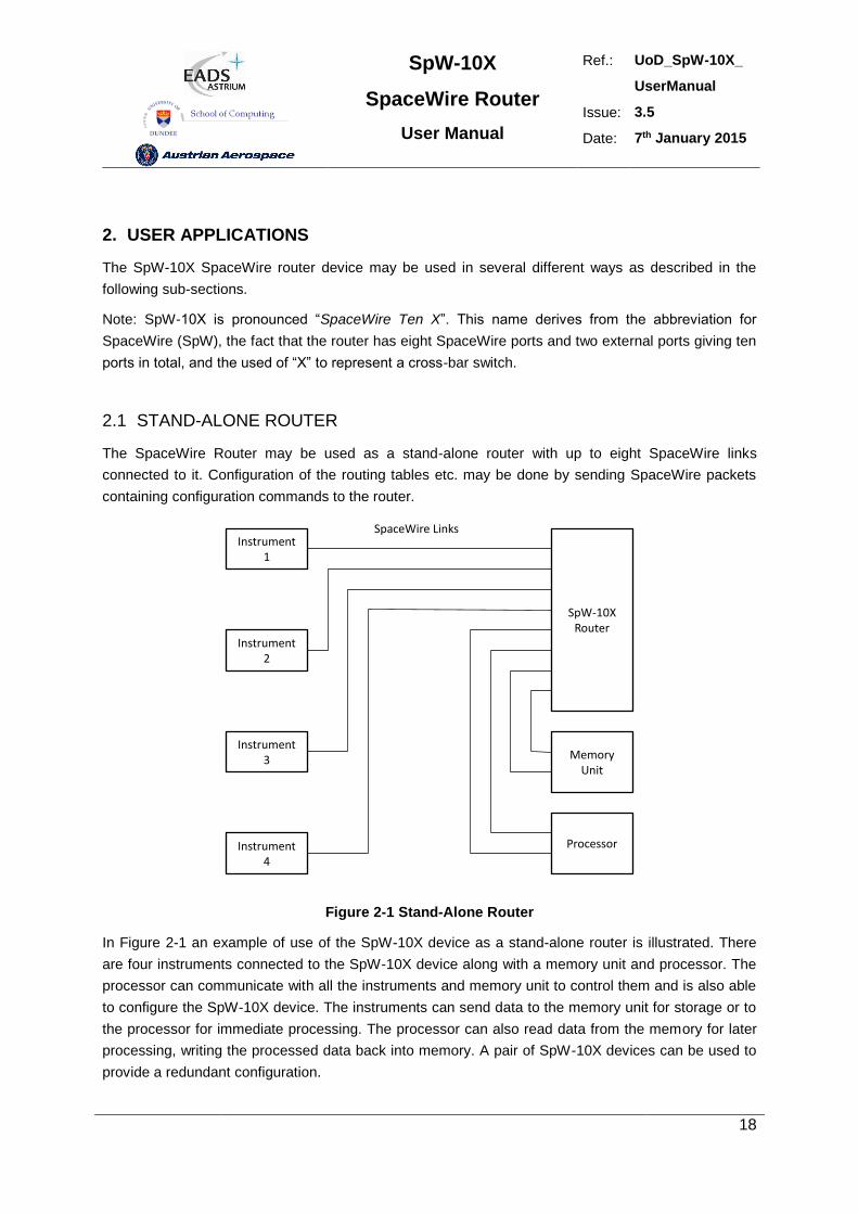
2.1 STAND-ALONE ROUTER
The SpaceWire Router may be used as a stand-alone router with up to eight SpaceWire links
connected to it. Configuration of the routing tables etc. may be done by sending SpaceWire packets
containing configuration commands to the router.
Instrument1
Instrument2
Instrument3
Instrument4
MemoryUnit
Processor
SpW-10XRouter
SpaceWire Links
Figure 2-1 Stand-Alone Router
In Figure 2-1 an example of use of the SpW-10X device as a stand-alone router is illustrated. There
are four instruments connected to the SpW-10X device along with a memory unit and processor. The
processor can communicate with all the instruments and memory unit to control them and is also able
to configure the SpW-10X device. The instruments can send data to the memory unit for storage or to
the processor for immediate processing. The processor can also read data from the memory for later
processing, writing the processed data back into memory. A pair of SpW-10X devices can be used to
provide a redundant configuration.
SpW-10X
SpaceWire Router
User Manual
Ref.: UoD_SpW-10X_
UserManual
Issue: 3.5
Date: 7th January 2015
19
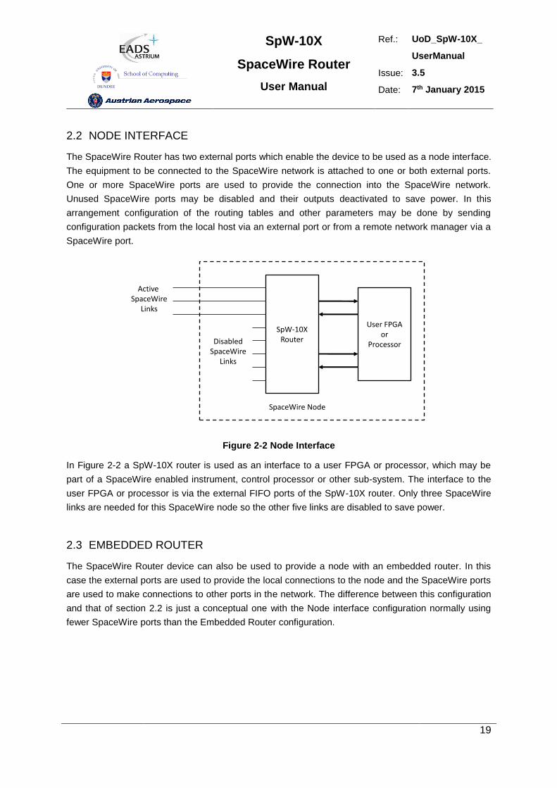
2.2 NODE INTERFACE
The SpaceWire Router has two external ports which enable the device to be used as a node interface.
The equipment to be connected to the SpaceWire network is attached to one or both external ports.
One or more SpaceWire ports are used to provide the connection into the SpaceWire network.
Unused SpaceWire ports may be disabled and their outputs deactivated to save power. In this
arrangement configuration of the routing tables and other parameters may be done by sending
configuration packets from the local host via an external port or from a remote network manager via a
SpaceWire port.
User FPGAor
Processor
SpW-10XRouter
Active SpaceWire
Links
DisabledSpaceWire
Links
SpaceWire Node
Figure 2-2 Node Interface
In Figure 2-2 a SpW-10X router is used as an interface to a user FPGA or processor, which may be
part of a SpaceWire enabled instrument, control processor or other sub-system. The interface to the
user FPGA or processor is via the external FIFO ports of the SpW-10X router. Only three SpaceWire
links are needed for this SpaceWire node so the other five links are disabled to save power.
2.3 EMBEDDED ROUTER
The SpaceWire Router device can also be used to provide a node with an embedded router. In this
case the external ports are used to provide the local connections to the node and the SpaceWire ports
are used to make connections to other ports in the network. The difference between this configuration
and that of section 2.2 is just a conceptual one with the Node interface configuration normally using
fewer SpaceWire ports than the Embedded Router configuration.
SpW-10X
SpaceWire Router
User Manual
Ref.: UoD_SpW-10X_
UserManual
Issue: 3.5
Date: 7th January 2015
20
Instrument1
Instrument2
Instrument3
Instrument4
MemoryUnit
ProcessorSpW-10X
Router
Instrument5
Instrument6
SpaceWire Node with Embedded Router
SpaceWire Links
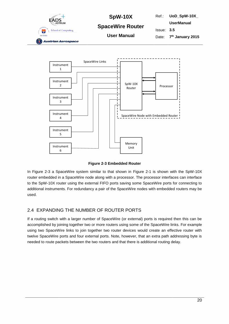
Figure 2-3 Embedded Router
In Figure 2-3 a SpaceWire system similar to that shown in Figure 2-1 is shown with the SpW-10X
router embedded in a SpaceWire node along with a processor. The processor interfaces can interface
to the SpW-10X router using the external FIFO ports saving some SpaceWire ports for connecting to
additional instruments. For redundancy a pair of the SpaceWire nodes with embedded routers may be
used.
2.4 EXPANDING THE NUMBER OF ROUTER PORTS
If a routing switch with a larger number of SpaceWire (or external) ports is required then this can be
accomplished by joining together two or more routers using some of the SpaceWire links. For example
using two SpaceWire links to join together two router devices would create an effective router with
twelve SpaceWire ports and four external ports. Note, however, that an extra path addressing byte is
needed to route packets between the two routers and that there is additional routing delay.
SpW-10X
SpaceWire Router
User Manual
Ref.: UoD_SpW-10X_
UserManual
Issue: 3.5
Date: 7th January 2015
21
SpW-10XRouter
SpW-10XRouter
SpaceWirePorts
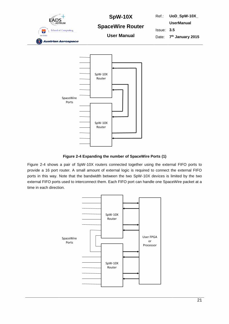
Figure 2-4 Expanding the number of SpaceWire Ports (1)
Figure 2-4 shows a pair of SpW-10X routers connected together using the external FIFO ports to
provide a 16 port router. A small amount of external logic is required to connect the external FIFO
ports in this way. Note that the bandwidth between the two SpW-10X devices is limited by the two
external FIFO ports used to interconnect them. Each FIFO port can handle one SpaceWire packet at a
time in each direction.
SpW-10XRouter
SpW-10XRouter
SpaceWirePorts
User FPGAor
Processor
SpW-10X
SpaceWire Router
User Manual
Ref.: UoD_SpW-10X_
UserManual
Issue: 3.5
Date: 7th January 2015
22
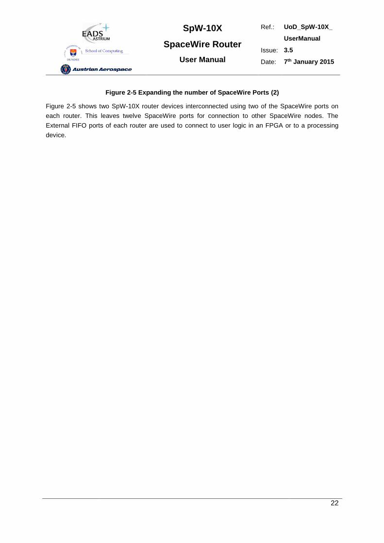
Figure 2-5 Expanding the number of SpaceWire Ports (2)
Figure 2-5 shows two SpW-10X router devices interconnected using two of the SpaceWire ports on
each router. This leaves twelve SpaceWire ports for connection to other SpaceWire nodes. The
External FIFO ports of each router are used to connect to user logic in an FPGA or to a processing
device.
SpW-10X
SpaceWire Router
User Manual
Ref.: UoD_SpW-10X_
UserManual
Issue: 3.5
Date: 7th January 2015
23
3. FUNCTIONAL OVERVIEW
A SpaceWire routing switch comprises a number of SpaceWire ports and a routing matrix. The routing
matrix enables packets arriving at one SpaceWire port to be transferred to and sent out of another port
on the routing switch. A SpaceWire routing switch is thus able to connect together many SpaceWire
nodes, providing a means of routing packets between the nodes connected to it.
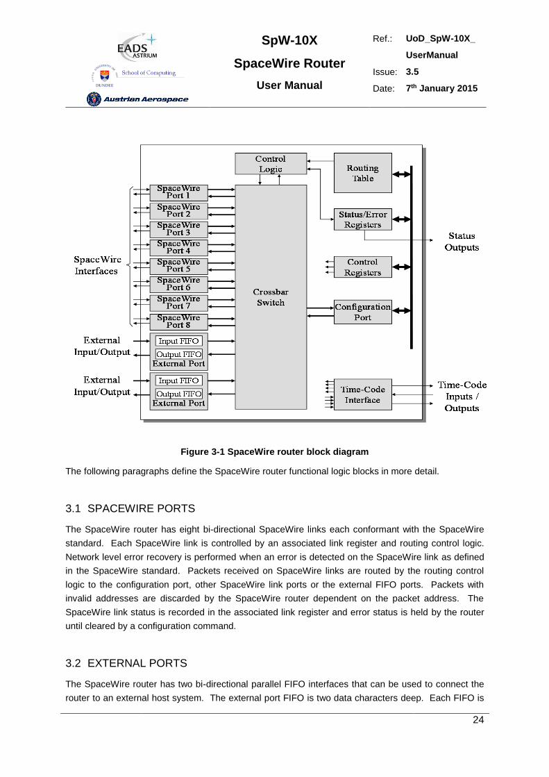
The SpW-10X SpaceWire router comprises the following functional logic blocks:
Eight SpaceWire bi-directional serial ports.
Two external parallel input/output ports each comprising an input FIFO and an output FIFO.
A crossbar switch connecting any input port to any output port.
An internal configuration port accessible via the crossbar switch from the external parallel
input/output port or the SpaceWire input/output ports.
A routing table accessible via the configuration port which holds the logical address to output
port mapping.
Control logic to control the operation of the switch, performing arbitration and group adaptive
routing.
Control registers than can be written and read by the configuration port and which hold control
information e.g. link operating speed.
An external time-code interface comprising tick_in, tick_out and current tick count value.
Internal status/error registers accessible via the configuration port.
Watchdog timers on all ports.
Internal status/error registers accessible via the configuration port using the RMAP protocol [2].
External status/error signals.
A block diagram of the routing switch is given in Figure 3-1.
SpW-10X
SpaceWire Router
User Manual
Ref.: UoD_SpW-10X_
UserManual
Issue: 3.5
Date: 7th January 2015
24
Figure 3-1 SpaceWire router block diagram
The following paragraphs define the SpaceWire router functional logic blocks in more detail.
3.1 SPACEWIRE PORTS
The SpaceWire router has eight bi-directional SpaceWire links each conformant with the SpaceWire
standard. Each SpaceWire link is controlled by an associated link register and routing control logic.
Network level error recovery is performed when an error is detected on the SpaceWire link as defined
in the SpaceWire standard. Packets received on SpaceWire links are routed by the routing control
logic to the configuration port, other SpaceWire link ports or the external FIFO ports. Packets with
invalid addresses are discarded by the SpaceWire router dependent on the packet address. The
SpaceWire link status is recorded in the associated link register and error status is held by the router
until cleared by a configuration command.
3.2 EXTERNAL PORTS
The SpaceWire router has two bi-directional parallel FIFO interfaces that can be used to connect the
router to an external host system. The external port FIFO is two data characters deep. Each FIFO is
SpW-10X
SpaceWire Router
User Manual
Ref.: UoD_SpW-10X_
UserManual
Issue: 3.5
Date: 7th January 2015
25
written to or read from synchronously with the 30MHz system clock. An eight-bit data interface and an
extra control bit for end of packet markers are provided by each external port FIFO. Packets received
by the external port are routed by the routing control logic to the configuration port, SpaceWire link
ports or the other external port dependent on the packet address. Packets with invalid addresses are
discarded by the SpaceWire router.
3.3 CONFIGURATION PORT
The SpaceWire router has one configuration port which performs read and write operations to internal
router registers. Packets are routed to the configuration port when a packet with a leading address
byte of zero is received. The Remote Memory Access Protocol (RMAP) [AD2] to access the
configuration port. A detailed description of the RMAP command packet format is provided in section
7.6. If an invalid command packet is received then the error is flagged to an associated status register
and the packet is discarded. The internal router registers are described in section 9.
3.4 ROUTING TABLE
The SpaceWire router routing table is set by the router command packets to assign logical addresses
to physical destination ports on the router. A group of destination ports can be set, in each routing
table location, to enable group adaptive routing. In group adaptive routing a packet can be routed to
its destination through one of a set of output ports dependent on which ports in the set are free to use.
When a packet is received with a logical address the routing table is checked by the routing control
logic and the packet is routed to the destination port when the port is ready.
Routing table locations are set to invalid at power on or at reset. An invalid routing address will cause
the packet to be spilled by the control logic. The routing table logical addresses can also be set to
support high priority and header deletion. High priority packets are routed before low priority packets
and header deletion of logical addresses can be used to support regional logical addressing (see
AD1).
3.5 ROUTING CONTROL LOGIC AND CROSSBAR
The routing control logic is responsible for arbitration of output ports, group adaptive routing and the
crossbar switching. Arbitration is performed when two or more source ports are requesting to use the
same destination port. A priority based arbitration scheme with two priority levels, high and low, is
used where high priority packets are routed before low priority packets. Fair arbitration is performed
on packets which have the same priority levels to ensure each packet gets equal access to the output
port.
Group adaptive routing control selects one of a number of output ports for sending out the source
packet.
SpW-10X
SpaceWire Router
User Manual
Ref.: UoD_SpW-10X_
UserManual
Issue: 3.5
Date: 7th January 2015
26
The crossbar switch connects an input port to an output port allowing data to flow from the input port
to the output port. Several input ports may be connected simultaneously to several output ports all
passing data. Two or more input ports may not be connected to a single output port. The crossbar
switch is a “non-blocking” type because the connection of one input port to an output port does not
prevent another input port being connected to another output port at the same time. It is possible for
all eight input ports to be each connected to an output port so that all input ports and output ports are
being used.
3.6 TIME-CODE PROCESSING
An internal time-code register is used in the router to allow the router to be a time-code master or a
time-code slave.
In master mode the time-code interface is used to provide a tick-in to the SpaceWire routing causing
time-codes to be propagated through the network. Two modes of time master operation are
supported, an automatic mode where a time-code is propagated on each external tick-in and a normal
mode where the time-code is propagated dependent on the external time-in signal.
In time-code slave mode a valid received time-code, one plus the value of the router time-code
register, causes a tick-out to be sent to the SpaceWire links and the external time-code interface. The
time-code is propagated to all time-code ports except the port on which the time-code was received. If
the time-code received is not one plus the value of the time-code register then the time-code register
is updated but the tick-out is not performed. In this way circular network paths do not cause a
constant stream of time-codes to be sent in a loop.
3.7 CONTROL/STATUS REGISTERS
The control and status registers in the SpaceWire router provide the means to control the operation of
the router, set the router configuration and parameters or monitor the status of the device. The
registers are accessed using RMAP [AD2] command packets received by the configuration port.
SpW-10X
SpaceWire Router
User Manual
Ref.: UoD_SpW-10X_
UserManual
Issue: 3.5
Date: 7th January 2015
27
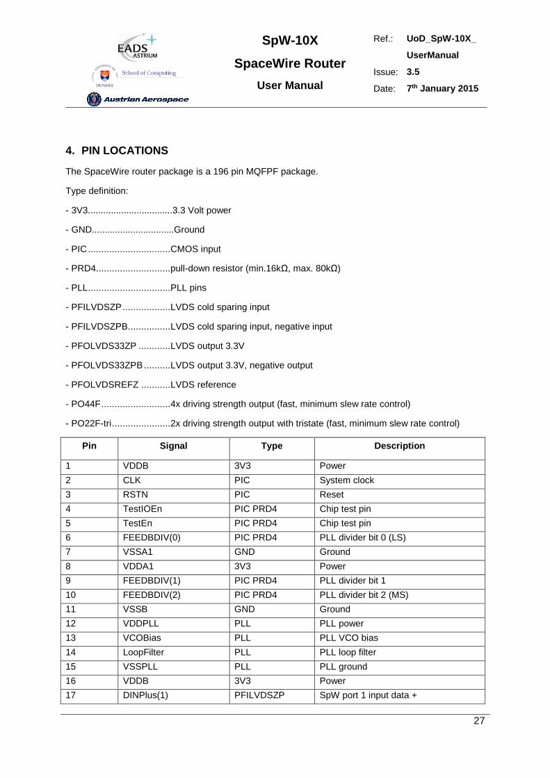
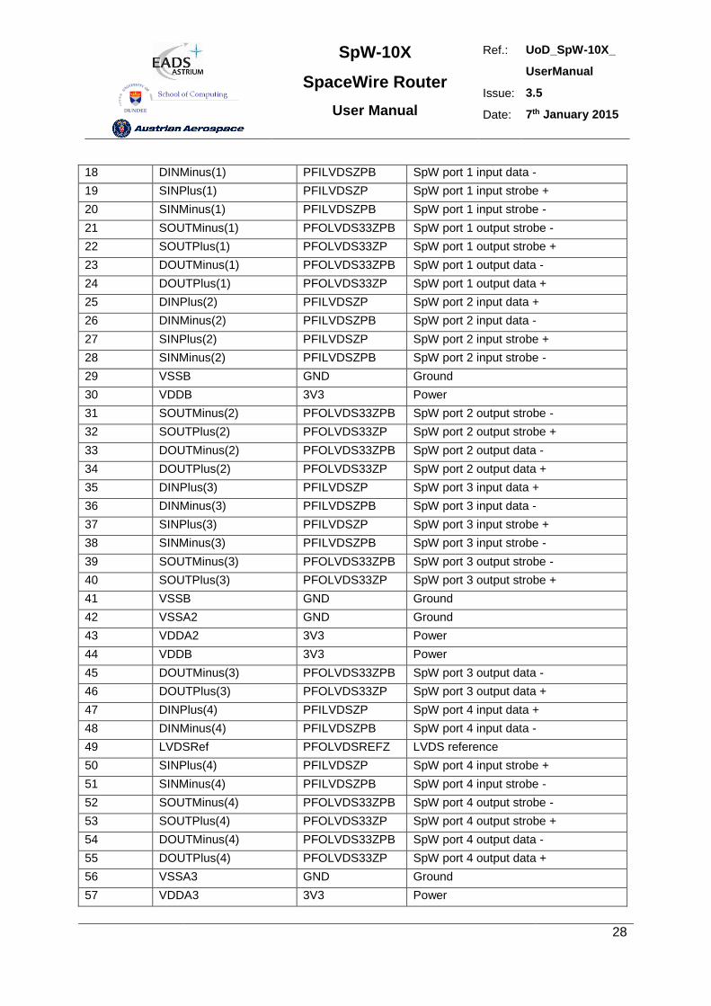
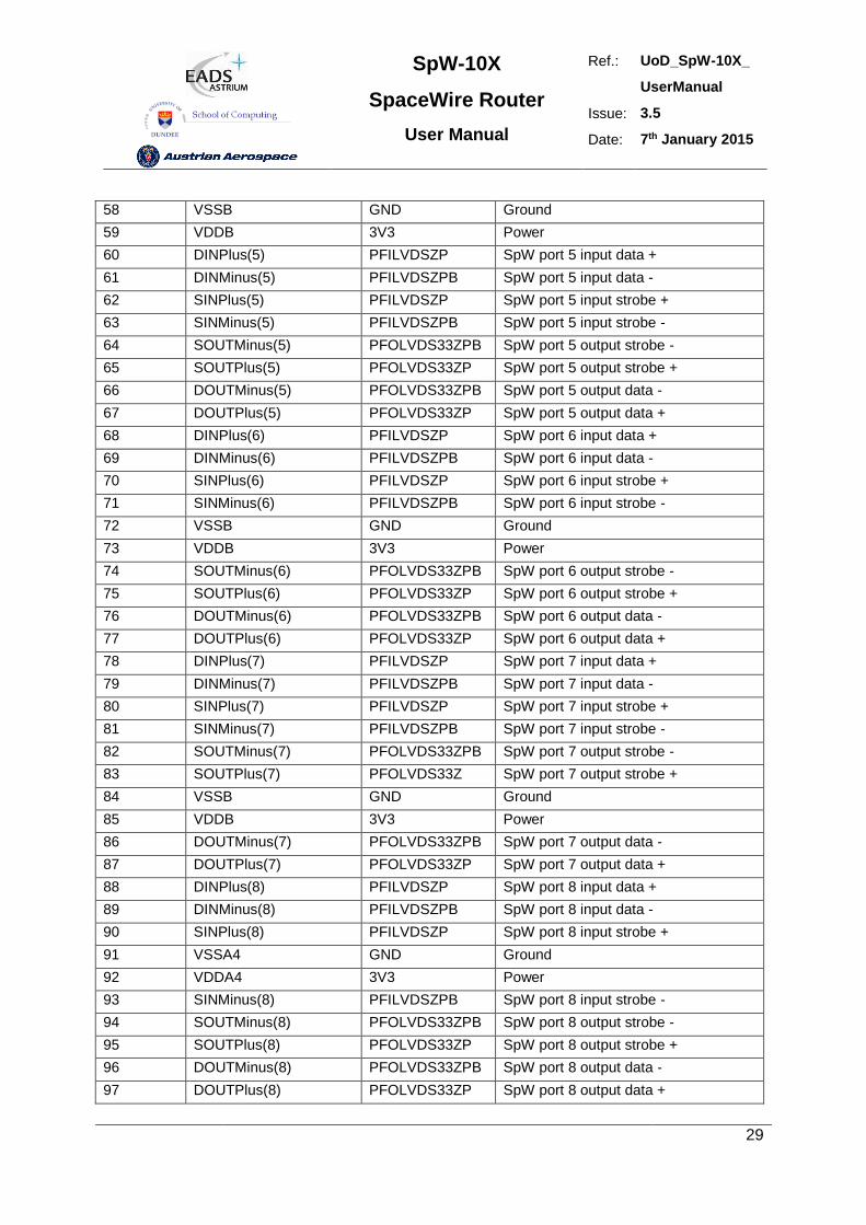
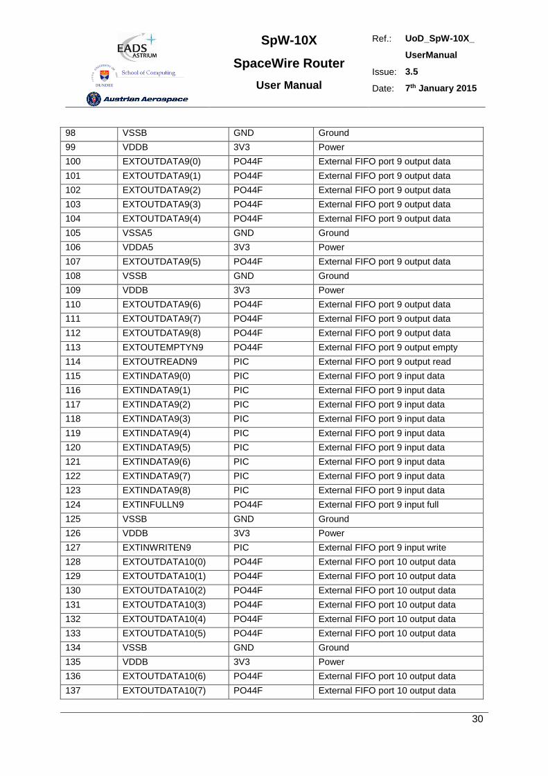
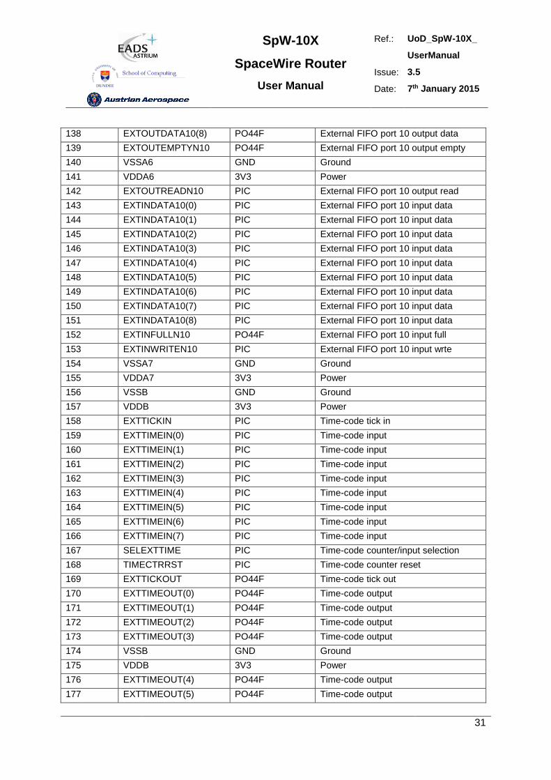
4. PIN LOCATIONS
The SpaceWire router package is a 196 pin MQFPF package.
Type definition:
- 3V3.................................3.3 Volt power
- GND................................Ground
- PIC ...............................CMOS input
- PRD4............................pull-down resistor (min.16kΩ, max. 80kΩ)
- PLL ...............................PLL pins
- PFILVDSZP ..................LVDS cold sparing input
- PFILVDSZPB ................LVDS cold sparing input, negative input
- PFOLVDS33ZP ............LVDS output 3.3V
- PFOLVDS33ZPB ..........LVDS output 3.3V, negative output
- PFOLVDSREFZ ...........LVDS reference
- PO44F ..........................4x driving strength output (fast, minimum slew rate control)
- PO22F-tri ......................2x driving strength output with tristate (fast, minimum slew rate control)
Pin Signal Type Description
1 VDDB 3V3 Power
2 CLK PIC System clock
3 RSTN PIC Reset
4 TestIOEn PIC PRD4 Chip test pin
5 TestEn PIC PRD4 Chip test pin
6 FEEDBDIV(0) PIC PRD4 PLL divider bit 0 (LS)
7 VSSA1 GND Ground
8 VDDA1 3V3 Power
9 FEEDBDIV(1) PIC PRD4 PLL divider bit 1
10 FEEDBDIV(2) PIC PRD4 PLL divider bit 2 (MS)
11 VSSB GND Ground
12 VDDPLL PLL PLL power
13 VCOBias PLL PLL VCO bias
14 LoopFilter PLL PLL loop filter
15 VSSPLL PLL PLL ground
16 VDDB 3V3 Power
17 DINPlus(1) PFILVDSZP SpW port 1 input data +
SpW-10X
SpaceWire Router
User Manual
Ref.: UoD_SpW-10X_
UserManual
Issue: 3.5
Date: 7th January 2015
28
18 DINMinus(1) PFILVDSZPB SpW port 1 input data -
19 SINPlus(1) PFILVDSZP SpW port 1 input strobe +
20 SINMinus(1) PFILVDSZPB SpW port 1 input strobe -
21 SOUTMinus(1) PFOLVDS33ZPB SpW port 1 output strobe -
22 SOUTPlus(1) PFOLVDS33ZP SpW port 1 output strobe +
23 DOUTMinus(1) PFOLVDS33ZPB SpW port 1 output data -
24 DOUTPlus(1) PFOLVDS33ZP SpW port 1 output data +
25 DINPlus(2) PFILVDSZP SpW port 2 input data +
26 DINMinus(2) PFILVDSZPB SpW port 2 input data -
27 SINPlus(2) PFILVDSZP SpW port 2 input strobe +
28 SINMinus(2) PFILVDSZPB SpW port 2 input strobe -
29 VSSB GND Ground
30 VDDB 3V3 Power
31 SOUTMinus(2) PFOLVDS33ZPB SpW port 2 output strobe -
32 SOUTPlus(2) PFOLVDS33ZP SpW port 2 output strobe +
33 DOUTMinus(2) PFOLVDS33ZPB SpW port 2 output data -
34 DOUTPlus(2) PFOLVDS33ZP SpW port 2 output data +
35 DINPlus(3) PFILVDSZP SpW port 3 input data +
36 DINMinus(3) PFILVDSZPB SpW port 3 input data -
37 SINPlus(3) PFILVDSZP SpW port 3 input strobe +
38 SINMinus(3) PFILVDSZPB SpW port 3 input strobe -
39 SOUTMinus(3) PFOLVDS33ZPB SpW port 3 output strobe -
40 SOUTPlus(3) PFOLVDS33ZP SpW port 3 output strobe +
41 VSSB GND Ground
42 VSSA2 GND Ground
43 VDDA2 3V3 Power
44 VDDB 3V3 Power
45 DOUTMinus(3) PFOLVDS33ZPB SpW port 3 output data -
46 DOUTPlus(3) PFOLVDS33ZP SpW port 3 output data +
47 DINPlus(4) PFILVDSZP SpW port 4 input data +
48 DINMinus(4) PFILVDSZPB SpW port 4 input data -
49 LVDSRef PFOLVDSREFZ LVDS reference
50 SINPlus(4) PFILVDSZP SpW port 4 input strobe +
51 SINMinus(4) PFILVDSZPB SpW port 4 input strobe -
52 SOUTMinus(4) PFOLVDS33ZPB SpW port 4 output strobe -
53 SOUTPlus(4) PFOLVDS33ZP SpW port 4 output strobe +
54 DOUTMinus(4) PFOLVDS33ZPB SpW port 4 output data -
55 DOUTPlus(4) PFOLVDS33ZP SpW port 4 output data +
56 VSSA3 GND Ground
57 VDDA3 3V3 Power
SpW-10X
SpaceWire Router
User Manual
Ref.: UoD_SpW-10X_
UserManual
Issue: 3.5
Date: 7th January 2015
29
58 VSSB GND Ground
59 VDDB 3V3 Power
60 DINPlus(5) PFILVDSZP SpW port 5 input data +
61 DINMinus(5) PFILVDSZPB SpW port 5 input data -
62 SINPlus(5) PFILVDSZP SpW port 5 input strobe +
63 SINMinus(5) PFILVDSZPB SpW port 5 input strobe -
64 SOUTMinus(5) PFOLVDS33ZPB SpW port 5 output strobe -
65 SOUTPlus(5) PFOLVDS33ZP SpW port 5 output strobe +
66 DOUTMinus(5) PFOLVDS33ZPB SpW port 5 output data -
67 DOUTPlus(5) PFOLVDS33ZP SpW port 5 output data +
68 DINPlus(6) PFILVDSZP SpW port 6 input data +
69 DINMinus(6) PFILVDSZPB SpW port 6 input data -
70 SINPlus(6) PFILVDSZP SpW port 6 input strobe +
71 SINMinus(6) PFILVDSZPB SpW port 6 input strobe -
72 VSSB GND Ground
73 VDDB 3V3 Power
74 SOUTMinus(6) PFOLVDS33ZPB SpW port 6 output strobe -
75 SOUTPlus(6) PFOLVDS33ZP SpW port 6 output strobe +
76 DOUTMinus(6) PFOLVDS33ZPB SpW port 6 output data -
77 DOUTPlus(6) PFOLVDS33ZP SpW port 6 output data +
78 DINPlus(7) PFILVDSZP SpW port 7 input data +
79 DINMinus(7) PFILVDSZPB SpW port 7 input data -
80 SINPlus(7) PFILVDSZP SpW port 7 input strobe +
81 SINMinus(7) PFILVDSZPB SpW port 7 input strobe -
82 SOUTMinus(7) PFOLVDS33ZPB SpW port 7 output strobe -
83 SOUTPlus(7) PFOLVDS33Z SpW port 7 output strobe +
84 VSSB GND Ground
85 VDDB 3V3 Power
86 DOUTMinus(7) PFOLVDS33ZPB SpW port 7 output data -
87 DOUTPlus(7) PFOLVDS33ZP SpW port 7 output data +
88 DINPlus(8) PFILVDSZP SpW port 8 input data +
89 DINMinus(8) PFILVDSZPB SpW port 8 input data -
90 SINPlus(8) PFILVDSZP SpW port 8 input strobe +
91 VSSA4 GND Ground
92 VDDA4 3V3 Power
93 SINMinus(8) PFILVDSZPB SpW port 8 input strobe -
94 SOUTMinus(8) PFOLVDS33ZPB SpW port 8 output strobe -
95 SOUTPlus(8) PFOLVDS33ZP SpW port 8 output strobe +
96 DOUTMinus(8) PFOLVDS33ZPB SpW port 8 output data -
97 DOUTPlus(8) PFOLVDS33ZP SpW port 8 output data +
SpW-10X
SpaceWire Router
User Manual
Ref.: UoD_SpW-10X_
UserManual
Issue: 3.5
Date: 7th January 2015
30
98 VSSB GND Ground
99 VDDB 3V3 Power
100 EXTOUTDATA9(0) PO44F External FIFO port 9 output data
101 EXTOUTDATA9(1) PO44F External FIFO port 9 output data
102 EXTOUTDATA9(2) PO44F External FIFO port 9 output data
103 EXTOUTDATA9(3) PO44F External FIFO port 9 output data
104 EXTOUTDATA9(4) PO44F External FIFO port 9 output data
105 VSSA5 GND Ground
106 VDDA5 3V3 Power
107 EXTOUTDATA9(5) PO44F External FIFO port 9 output data
108 VSSB GND Ground
109 VDDB 3V3 Power
110 EXTOUTDATA9(6) PO44F External FIFO port 9 output data
111 EXTOUTDATA9(7) PO44F External FIFO port 9 output data
112 EXTOUTDATA9(8) PO44F External FIFO port 9 output data
113 EXTOUTEMPTYN9 PO44F External FIFO port 9 output empty
114 EXTOUTREADN9 PIC External FIFO port 9 output read
115 EXTINDATA9(0) PIC External FIFO port 9 input data
116 EXTINDATA9(1) PIC External FIFO port 9 input data
117 EXTINDATA9(2) PIC External FIFO port 9 input data
118 EXTINDATA9(3) PIC External FIFO port 9 input data
119 EXTINDATA9(4) PIC External FIFO port 9 input data
120 EXTINDATA9(5) PIC External FIFO port 9 input data
121 EXTINDATA9(6) PIC External FIFO port 9 input data
122 EXTINDATA9(7) PIC External FIFO port 9 input data
123 EXTINDATA9(8) PIC External FIFO port 9 input data
124 EXTINFULLN9 PO44F External FIFO port 9 input full
125 VSSB GND Ground
126 VDDB 3V3 Power
127 EXTINWRITEN9 PIC External FIFO port 9 input write
128 EXTOUTDATA10(0) PO44F External FIFO port 10 output data
129 EXTOUTDATA10(1) PO44F External FIFO port 10 output data
130 EXTOUTDATA10(2) PO44F External FIFO port 10 output data
131 EXTOUTDATA10(3) PO44F External FIFO port 10 output data
132 EXTOUTDATA10(4) PO44F External FIFO port 10 output data
133 EXTOUTDATA10(5) PO44F External FIFO port 10 output data
134 VSSB GND Ground
135 VDDB 3V3 Power
136 EXTOUTDATA10(6) PO44F External FIFO port 10 output data
137 EXTOUTDATA10(7) PO44F External FIFO port 10 output data
SpW-10X
SpaceWire Router
User Manual
Ref.: UoD_SpW-10X_
UserManual
Issue: 3.5
Date: 7th January 2015
31
138 EXTOUTDATA10(8) PO44F External FIFO port 10 output data
139 EXTOUTEMPTYN10 PO44F External FIFO port 10 output empty
140 VSSA6 GND Ground
141 VDDA6 3V3 Power
142 EXTOUTREADN10 PIC External FIFO port 10 output read
143 EXTINDATA10(0) PIC External FIFO port 10 input data
144 EXTINDATA10(1) PIC External FIFO port 10 input data
145 EXTINDATA10(2) PIC External FIFO port 10 input data
146 EXTINDATA10(3) PIC External FIFO port 10 input data
147 EXTINDATA10(4) PIC External FIFO port 10 input data
148 EXTINDATA10(5) PIC External FIFO port 10 input data
149 EXTINDATA10(6) PIC External FIFO port 10 input data
150 EXTINDATA10(7) PIC External FIFO port 10 input data
151 EXTINDATA10(8) PIC External FIFO port 10 input data
152 EXTINFULLN10 PO44F External FIFO port 10 input full
153 EXTINWRITEN10 PIC External FIFO port 10 input wrte
154 VSSA7 GND Ground
155 VDDA7 3V3 Power
156 VSSB GND Ground
157 VDDB 3V3 Power
158 EXTTICKIN PIC Time-code tick in
159 EXTTIMEIN(0) PIC Time-code input
160 EXTTIMEIN(1) PIC Time-code input
161 EXTTIMEIN(2) PIC Time-code input
162 EXTTIMEIN(3) PIC Time-code input
163 EXTTIMEIN(4) PIC Time-code input
164 EXTTIMEIN(5) PIC Time-code input
165 EXTTIMEIN(6) PIC Time-code input
166 EXTTIMEIN(7) PIC Time-code input
167 SELEXTTIME PIC Time-code counter/input selection
168 TIMECTRRST PIC Time-code counter reset
169 EXTTICKOUT PO44F Time-code tick out
170 EXTTIMEOUT(0) PO44F Time-code output
171 EXTTIMEOUT(1) PO44F Time-code output
172 EXTTIMEOUT(2) PO44F Time-code output
173 EXTTIMEOUT(3) PO44F Time-code output
174 VSSB GND Ground
175 VDDB 3V3 Power
176 EXTTIMEOUT(4) PO44F Time-code output
177 EXTTIMEOUT(5) PO44F Time-code output
SpW-10X
SpaceWire Router
User Manual
Ref.: UoD_SpW-10X_
UserManual
Issue: 3.5
Date: 7th January 2015
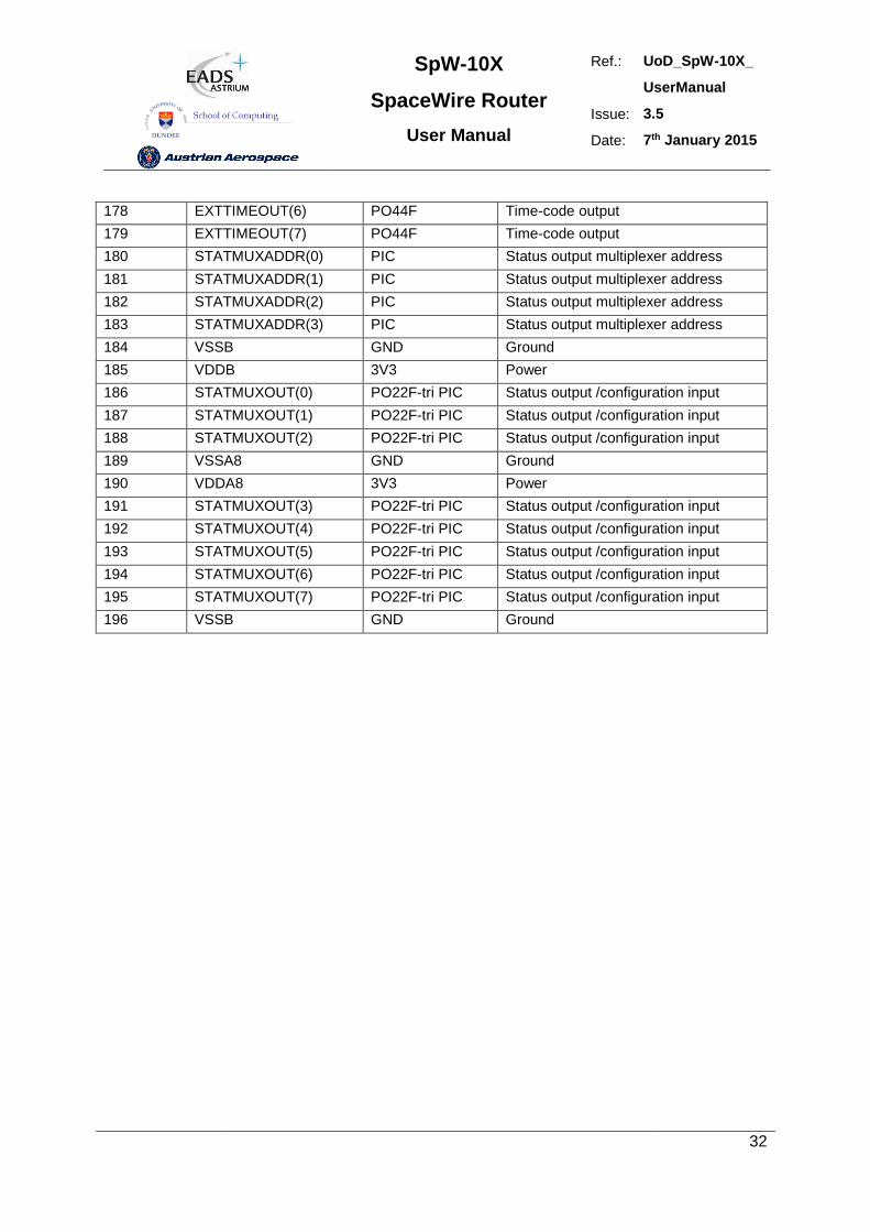
32
178 EXTTIMEOUT(6) PO44F Time-code output
179 EXTTIMEOUT(7) PO44F Time-code output
180 STATMUXADDR(0) PIC Status output multiplexer address
181 STATMUXADDR(1) PIC Status output multiplexer address
182 STATMUXADDR(2) PIC Status output multiplexer address
183 STATMUXADDR(3) PIC Status output multiplexer address
184 VSSB GND Ground
185 VDDB 3V3 Power
186 STATMUXOUT(0) PO22F-tri PIC Status output /configuration input
187 STATMUXOUT(1) PO22F-tri PIC Status output /configuration input
188 STATMUXOUT(2) PO22F-tri PIC Status output /configuration input
189 VSSA8 GND Ground
190 VDDA8 3V3 Power
191 STATMUXOUT(3) PO22F-tri PIC Status output /configuration input
192 STATMUXOUT(4) PO22F-tri PIC Status output /configuration input
193 STATMUXOUT(5) PO22F-tri PIC Status output /configuration input
194 STATMUXOUT(6) PO22F-tri PIC Status output /configuration input
195 STATMUXOUT(7) PO22F-tri PIC Status output /configuration input
196 VSSB GND Ground
SpW-10X
SpaceWire Router
User Manual
Ref.: UoD_SpW-10X_
UserManual
Issue: 3.5
Date: 7th January 2015
33
5. DEVICE INTERFACE
The device pins used by each interface are described in this section. There is a table for each type of
interface listing the signals in that interface. These tables have the following fields:
Pin No: The device pin number
Signal: The name of the signal
Dir: The direction of the signal; in, out or in/out
Description: An explanation of what the signal does.
Type: The type of signal
The sections below define the pin out of the SpaceWire router. Its interfaces are split into several
types, separated by headings for clarity:
5.1 Global signals: clock and reset
5.2 SpaceWire interface signals
5.3 External port signals
5.4 Time-code interface signals
5.5 Configuration signals
5.6 Reset configuration signals
5.7 Power and Ground
The following signal types are used in the SpaceWire Router:
CMOS3V3 3.3 Volt CMOS logic
LVDS Low Voltage Differential Signal
3V3 3.3 Volt power
GND Ground
5.1 GLOBAL SIGNALS
The global system clock and reset signals are listed in Table 5-1.
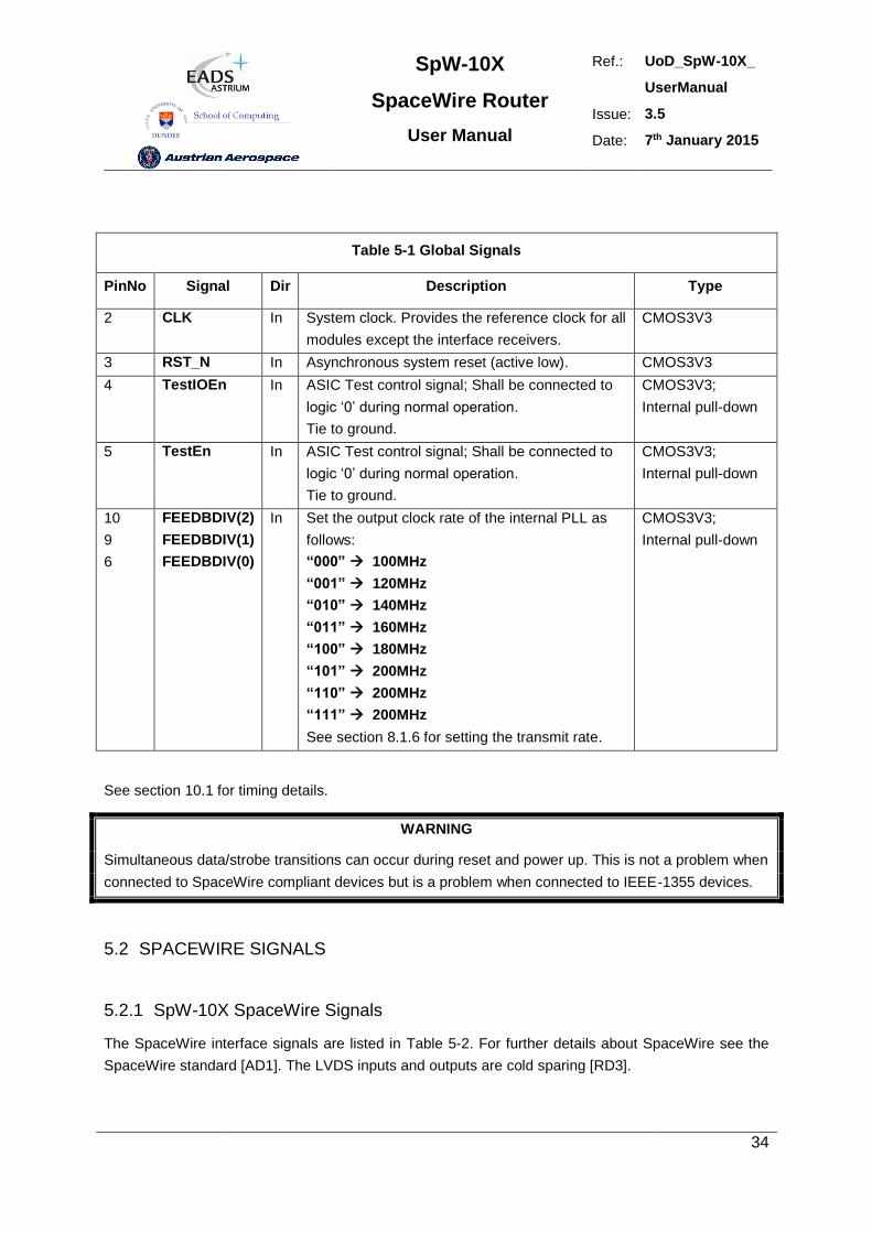
SpW-10X
SpaceWire Router
User Manual
Ref.: UoD_SpW-10X_
UserManual
Issue: 3.5
Date: 7th January 2015
34
Table 5-1 Global Signals
PinNo Signal Dir Description Type
2 CLK In System clock. Provides the reference clock for all
modules except the interface receivers.
CMOS3V3
3 RST_N In Asynchronous system reset (active low). CMOS3V3
4 TestIOEn In ASIC Test control signal; Shall be connected to
logic ‘0’ during normal operation.
Tie to ground.
CMOS3V3;
Internal pull-down
5 TestEn In ASIC Test control signal; Shall be connected to
logic ‘0’ during normal operation.
Tie to ground.
CMOS3V3;
Internal pull-down
10
9
6
FEEDBDIV(2)
FEEDBDIV(1)
FEEDBDIV(0)
In Set the output clock rate of the internal PLL as
follows:
“000” 100MHz
“001” 120MHz
“010” 140MHz
“011” 160MHz
“100” 180MHz
“101” 200MHz
“110” 200MHz
“111” 200MHz
See section 8.1.6 for setting the transmit rate.
CMOS3V3;
Internal pull-down
See section 10.1 for timing details.
WARNING
Simultaneous data/strobe transitions can occur during reset and power up. This is not a problem when
connected to SpaceWire compliant devices but is a problem when connected to IEEE-1355 devices.
5.2 SPACEWIRE SIGNALS
5.2.1 SpW-10X SpaceWire Signals
The SpaceWire interface signals are listed in Table 5-2. For further details about SpaceWire see the
SpaceWire standard [AD1]. The LVDS inputs and outputs are cold sparing [RD3].
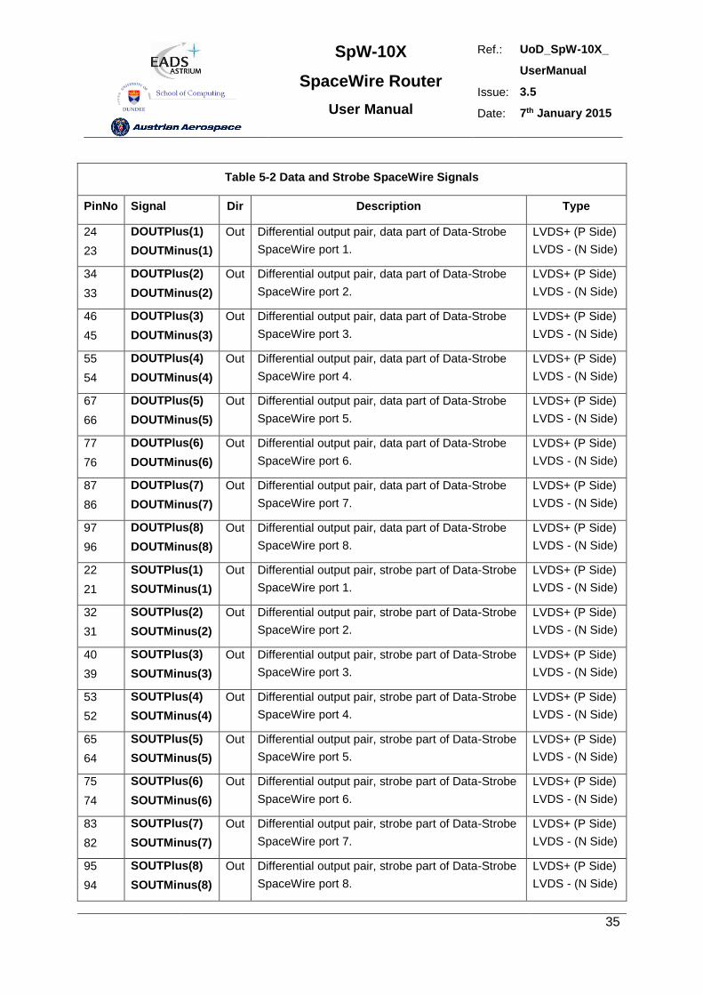
SpW-10X
SpaceWire Router
User Manual
Ref.: UoD_SpW-10X_
UserManual
Issue: 3.5
Date: 7th January 2015
35
Table 5-2 Data and Strobe SpaceWire Signals
PinNo Signal Dir Description Type
24
23
DOUTPlus(1)
DOUTMinus(1)
Out Differential output pair, data part of Data-Strobe
SpaceWire port 1.
LVDS+ (P Side)
LVDS - (N Side)
34
33
DOUTPlus(2)
DOUTMinus(2)
Out Differential output pair, data part of Data-Strobe
SpaceWire port 2.
LVDS+ (P Side)
LVDS - (N Side)
46
45
DOUTPlus(3)
DOUTMinus(3)
Out Differential output pair, data part of Data-Strobe
SpaceWire port 3.
LVDS+ (P Side)
LVDS - (N Side)
55
54
DOUTPlus(4)
DOUTMinus(4)
Out Differential output pair, data part of Data-Strobe
SpaceWire port 4.
LVDS+ (P Side)
LVDS - (N Side)
67
66
DOUTPlus(5)
DOUTMinus(5)
Out Differential output pair, data part of Data-Strobe
SpaceWire port 5.
LVDS+ (P Side)
LVDS - (N Side)
77
76
DOUTPlus(6)
DOUTMinus(6)
Out Differential output pair, data part of Data-Strobe
SpaceWire port 6.
LVDS+ (P Side)
LVDS - (N Side)
87
86
DOUTPlus(7)
DOUTMinus(7)
Out Differential output pair, data part of Data-Strobe
SpaceWire port 7.
LVDS+ (P Side)
LVDS - (N Side)
97
96
DOUTPlus(8)
DOUTMinus(8)
Out Differential output pair, data part of Data-Strobe
SpaceWire port 8.
LVDS+ (P Side)
LVDS - (N Side)
22
21
SOUTPlus(1)
SOUTMinus(1)
Out Differential output pair, strobe part of Data-Strobe
SpaceWire port 1.
LVDS+ (P Side)
LVDS - (N Side)
32
31
SOUTPlus(2)
SOUTMinus(2)
Out Differential output pair, strobe part of Data-Strobe
SpaceWire port 2.
LVDS+ (P Side)
LVDS - (N Side)
40
39
SOUTPlus(3)
SOUTMinus(3)
Out Differential output pair, strobe part of Data-Strobe
SpaceWire port 3.
LVDS+ (P Side)
LVDS - (N Side)
53
52
SOUTPlus(4)
SOUTMinus(4)
Out Differential output pair, strobe part of Data-Strobe
SpaceWire port 4.
LVDS+ (P Side)
LVDS - (N Side)
65
64
SOUTPlus(5)
SOUTMinus(5)
Out Differential output pair, strobe part of Data-Strobe
SpaceWire port 5.
LVDS+ (P Side)
LVDS - (N Side)
75
74
SOUTPlus(6)
SOUTMinus(6)
Out Differential output pair, strobe part of Data-Strobe
SpaceWire port 6.
LVDS+ (P Side)
LVDS - (N Side)
83
82
SOUTPlus(7)
SOUTMinus(7)
Out Differential output pair, strobe part of Data-Strobe
SpaceWire port 7.
LVDS+ (P Side)
LVDS - (N Side)
95
94
SOUTPlus(8)
SOUTMinus(8)
Out Differential output pair, strobe part of Data-Strobe
SpaceWire port 8.
LVDS+ (P Side)
LVDS - (N Side)
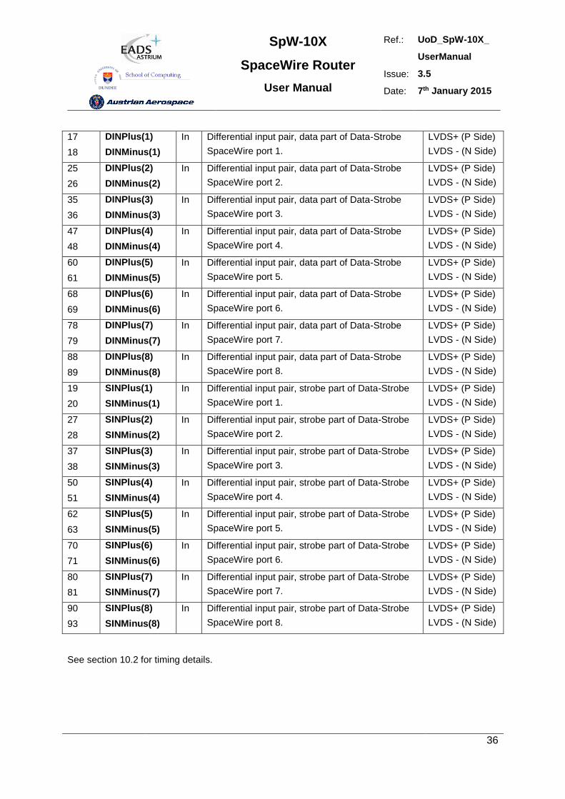
SpW-10X
SpaceWire Router
User Manual
Ref.: UoD_SpW-10X_
UserManual
Issue: 3.5
Date: 7th January 2015
36
17
18
DINPlus(1)
DINMinus(1)
In Differential input pair, data part of Data-Strobe
SpaceWire port 1.
LVDS+ (P Side)
LVDS - (N Side)
25
26
DINPlus(2)
DINMinus(2)
In Differential input pair, data part of Data-Strobe
SpaceWire port 2.
LVDS+ (P Side)
LVDS - (N Side)
35
36
DINPlus(3)
DINMinus(3)
In Differential input pair, data part of Data-Strobe
SpaceWire port 3.
LVDS+ (P Side)
LVDS - (N Side)
47
48
DINPlus(4)
DINMinus(4)
In Differential input pair, data part of Data-Strobe
SpaceWire port 4.
LVDS+ (P Side)
LVDS - (N Side)
60
61
DINPlus(5)
DINMinus(5)
In Differential input pair, data part of Data-Strobe
SpaceWire port 5.
LVDS+ (P Side)
LVDS - (N Side)
68
69
DINPlus(6)
DINMinus(6)
In Differential input pair, data part of Data-Strobe
SpaceWire port 6.
LVDS+ (P Side)
LVDS - (N Side)
78
79
DINPlus(7)
DINMinus(7)
In Differential input pair, data part of Data-Strobe
SpaceWire port 7.
LVDS+ (P Side)
LVDS - (N Side)
88
89
DINPlus(8)
DINMinus(8)
In Differential input pair, data part of Data-Strobe
SpaceWire port 8.
LVDS+ (P Side)
LVDS - (N Side)
19
20
SINPlus(1)
SINMinus(1)
In Differential input pair, strobe part of Data-Strobe
SpaceWire port 1.
LVDS+ (P Side)
LVDS - (N Side)
27
28
SINPlus(2)
SINMinus(2)
In Differential input pair, strobe part of Data-Strobe
SpaceWire port 2.
LVDS+ (P Side)
LVDS - (N Side)
37
38
SINPlus(3)
SINMinus(3)
In Differential input pair, strobe part of Data-Strobe
SpaceWire port 3.
LVDS+ (P Side)
LVDS - (N Side)
50
51
SINPlus(4)
SINMinus(4)
In Differential input pair, strobe part of Data-Strobe
SpaceWire port 4.
LVDS+ (P Side)
LVDS - (N Side)
62
63
SINPlus(5)
SINMinus(5)
In Differential input pair, strobe part of Data-Strobe
SpaceWire port 5.
LVDS+ (P Side)
LVDS - (N Side)
70
71
SINPlus(6)
SINMinus(6)
In Differential input pair, strobe part of Data-Strobe
SpaceWire port 6.
LVDS+ (P Side)
LVDS - (N Side)
80
81
SINPlus(7)
SINMinus(7)
In Differential input pair, strobe part of Data-Strobe
SpaceWire port 7.
LVDS+ (P Side)
LVDS - (N Side)
90
93
SINPlus(8)
SINMinus(8)
In Differential input pair, strobe part of Data-Strobe
SpaceWire port 8.
LVDS+ (P Side)
LVDS - (N Side)
See section 10.2 for timing details.
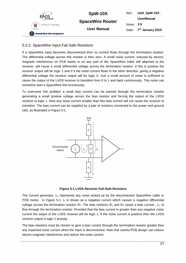
SpW-10X
SpaceWire Router
User Manual
Ref.: UoD_SpW-10X_
UserManual
Issue: 3.5
Date: 7th January 2015
37
5.2.2 SpaceWire Input Fail Safe Resistors
If a SpaceWire input becomes disconnected then no current flows through the termination resistor.
The differential voltage across this resistor is then zero. A small noise current, induced by electro-
magnetic interference on PCB tracks or on any part of the SpaceWire cable still attached to the
receiver, will cause a small differential voltage across the termination resistor. If this is positive the
receiver output will be logic 1 and if it the noise current flows in the other direction, giving a negative
differential voltage the receiver output will be logic 0. Just a small amount of noise is sufficient to
cause the output of the LVDS receiver to transition from 0 to 1 and back continuously. This noise can
sometime start a SpaceWire link erroneously.
To overcome this problem a small bias current can be passed through the termination resistor
generating a small positive voltage across the bias resistor and forcing the output of the LVDS
receiver to logic 1. Now any noise current smaller than this bias current will not cause the receiver to
transition. The bias current can be supplied by a pair of resistors connected to the power and ground
rails, as illustrated in Figure 5-1.
R1
RT
R2
In In Ib
DisconnectedInputs
+
-
3V3
Figure 5-1 LVDS Receiver Fail-Safe Resistors
The current generator, In, represents any noise picked up by the disconnected SpaceWire cable or
PCB tracks. In Figure 5-1, In is shown as a negative current which causes a negative differential
voltage across the termination resistor RT. The bias resistors R1 and R2 cause a bias current , In, to
flow through the termination resistor. Provided that the bias current is greater than any negative noise
current the output of the LVDS receiver will be logic 1. If the noise current is positive then the LVDS
receiver output is logic 1 anyway.
The bias resistors must be chosen to give a bias current through the termination resistor greater than
any expected noise current when the input is disconnected. Note that careful PCB design can reduce
electro-magnetic interference and reduce the noise current.
SpW-10X
SpaceWire Router
User Manual
Ref.: UoD_SpW-10X_
UserManual
Issue: 3.5
Date: 7th January 2015
38
The bias resistor values are determined as follows:
1. Determine the amount of noise protection required.
E.g. if the maximum noise voltage expected is less than 10 mV then the bias current required is Ib =10
mV/100= 0.1 mA. Note: the bias current should be at least an order of magnitude lower than the 3
mA current loop used for normal LVDS operation.
2. Determine the total resistance, RB, from bias supply VDD to ground, RB = VDD / Ib.
E.g. RB = 3.3 V/0.1 mA = 33 k. Since RT is much smaller than this value it can be ignored.
3. Determine the ratio of R2 to the total resistance, RB.
The line common mode voltage, Vcm, should be 1.25 V so the ratio of R2 to RB is R2/RB = 1.25 V/3.3 V
= 0.379.
4. Calculate the value of R2 and round down to a standard value.
E.g. R2 = 0.379 x 33 k = 12.5 kso the nearest standard value is 12 k (E24 series).
5. Now recalculate the value of RB to give the required line common mode voltage
E.g. RB = 12k / 0.379 V = 31.6 k.
6. Calculate the value of R1, R1 = RB - R2, and round to a standard value.
E.g. R1 = 31.6 k – 12 k = 19.6 k, so the nearest standard value is 20 k (E24 series) or 19.6 k
(E48 series).
7. Check the maximum noise voltage and common mode voltage.
E.g. Vn = 3.3 V x 100 / 32 k = 10.3 mV and Vcm = 3.3 V x 12 k32 k = 1.24 V
If the noise on the disconnected inputs is likely to be higher than 10 mV then other resistor values
need to be calculated.
For further details see RD1 and RD2.
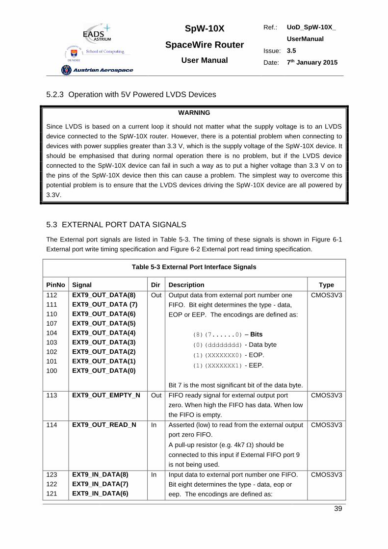
SpW-10X
SpaceWire Router
User Manual
Ref.: UoD_SpW-10X_
UserManual
Issue: 3.5
Date: 7th January 2015
39
5.2.3 Operation with 5V Powered LVDS Devices
WARNING
Since LVDS is based on a current loop it should not matter what the supply voltage is to an LVDS
device connected to the SpW-10X router. However, there is a potential problem when connecting to
devices with power supplies greater than 3.3 V, which is the supply voltage of the SpW-10X device. It
should be emphasised that during normal operation there is no problem, but if the LVDS device
connected to the SpW-10X device can fail in such a way as to put a higher voltage than 3.3 V on to
the pins of the SpW-10X device then this can cause a problem. The simplest way to overcome this
potential problem is to ensure that the LVDS devices driving the SpW-10X device are all powered by
3.3V.
5.3 EXTERNAL PORT DATA SIGNALS
The External port signals are listed in Table 5-3. The timing of these signals is shown in Figure 6-1
External port write timing specification and Figure 6-2 External port read timing specification.
Table 5-3 External Port Interface Signals
PinNo Signal Dir Description Type
112
111
110
107
104
103
102
101
100
EXT9_OUT_DATA(8)
EXT9_OUT_DATA (7)
EXT9_OUT_DATA(6)
EXT9_OUT_DATA(5)
EXT9_OUT_DATA(4)
EXT9_OUT_DATA(3)
EXT9_OUT_DATA(2)
EXT9_OUT_DATA(1)
EXT9_OUT_DATA(0)
Out Output data from external port number one
FIFO. Bit eight determines the type - data,
EOP or EEP. The encodings are defined as:
(8)(7......0) – Bits
(0)(dddddddd) - Data byte
(1)(XXXXXXX0) - EOP.
(1)(XXXXXXX1) - EEP.
Bit 7 is the most significant bit of the data byte.
CMOS3V3
113 EXT9_OUT_EMPTY_N Out FIFO ready signal for external output port
zero. When high the FIFO has data. When low
the FIFO is empty.
CMOS3V3
114 EXT9_OUT_READ_N In Asserted (low) to read from the external output
port zero FIFO.
A pull-up resistor (e.g. 4k7 ) should be
connected to this input if External FIFO port 9
is not being used.
CMOS3V3
123
122
121
EXT9_IN_DATA(8)
EXT9_IN_DATA(7)
EXT9_IN_DATA(6)
In Input data to external port number one FIFO.
Bit eight determines the type - data, eop or
eep. The encodings are defined as:
CMOS3V3
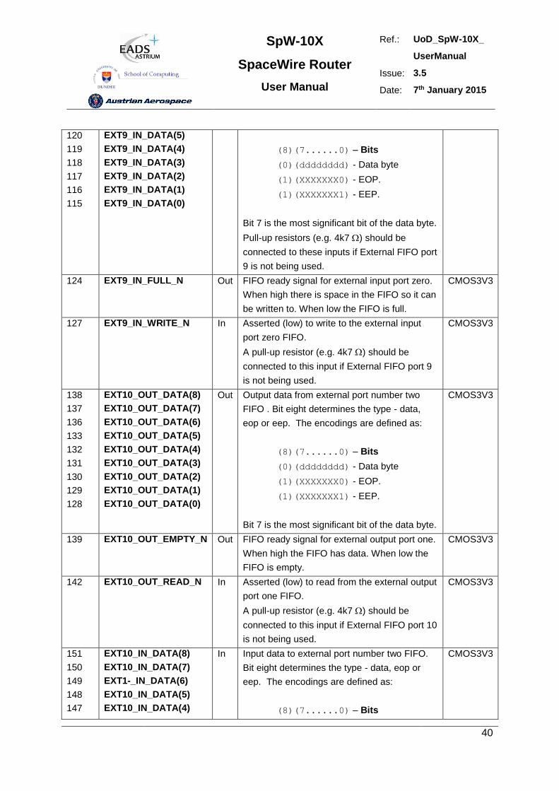
SpW-10X
SpaceWire Router
User Manual
Ref.: UoD_SpW-10X_
UserManual
Issue: 3.5
Date: 7th January 2015
40
120
119
118
117
116
115
EXT9_IN_DATA(5)
EXT9_IN_DATA(4)
EXT9_IN_DATA(3)
EXT9_IN_DATA(2)
EXT9_IN_DATA(1)
EXT9_IN_DATA(0)
(8)(7......0) – Bits
(0)(dddddddd) - Data byte
(1)(XXXXXXX0) - EOP.
(1)(XXXXXXX1) - EEP.
Bit 7 is the most significant bit of the data byte.
Pull-up resistors (e.g. 4k7 ) should be
connected to these inputs if External FIFO port
9 is not being used.
124 EXT9_IN_FULL_N Out FIFO ready signal for external input port zero.
When high there is space in the FIFO so it can
be written to. When low the FIFO is full.
CMOS3V3
127 EXT9_IN_WRITE_N In Asserted (low) to write to the external input
port zero FIFO.
A pull-up resistor (e.g. 4k7 ) should be
connected to this input if External FIFO port 9
is not being used.
CMOS3V3
138
137
136
133
132
131
130
129
128
EXT10_OUT_DATA(8)
EXT10_OUT_DATA(7)
EXT10_OUT_DATA(6)
EXT10_OUT_DATA(5)
EXT10_OUT_DATA(4)
EXT10_OUT_DATA(3)
EXT10_OUT_DATA(2)
EXT10_OUT_DATA(1)
EXT10_OUT_DATA(0)
Out Output data from external port number two
FIFO . Bit eight determines the type - data,
eop or eep. The encodings are defined as:
(8)(7......0) – Bits
(0)(dddddddd) - Data byte
(1)(XXXXXXX0) - EOP.
(1)(XXXXXXX1) - EEP.
Bit 7 is the most significant bit of the data byte.
CMOS3V3
139 EXT10_OUT_EMPTY_N Out FIFO ready signal for external output port one.
When high the FIFO has data. When low the
FIFO is empty.
CMOS3V3
142 EXT10_OUT_READ_N In Asserted (low) to read from the external output
port one FIFO.
A pull-up resistor (e.g. 4k7 ) should be
connected to this input if External FIFO port 10
is not being used.
CMOS3V3
151
150
149
148
147
EXT10_IN_DATA(8)
EXT10_IN_DATA(7)
EXT1-_IN_DATA(6)
EXT10_IN_DATA(5)
EXT10_IN_DATA(4)
In Input data to external port number two FIFO.
Bit eight determines the type - data, eop or
eep. The encodings are defined as:
(8)(7......0) – Bits
CMOS3V3
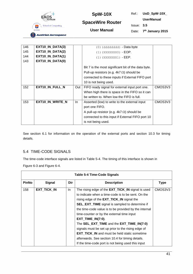
SpW-10X
SpaceWire Router
User Manual
Ref.: UoD_SpW-10X_
UserManual
Issue: 3.5
Date: 7th January 2015
41
146
145
144
143
EXT10_IN_DATA(3)
EXT10_IN_DATA(2)
EXT10_IN_DATA(1)
EXT10_IN_DATA(0)
(0)(dddddddd) - Data byte
(1)(XXXXXXX0) - EOP.
(1)(XXXXXXX1) - EEP.
Bit 7 is the most significant bit of the data byte.
Pull-up resistors (e.g. 4k7 ) should be
connected to these inputs if External FIFO port
10 is not being used.
152 EXT10_IN_FULL_N Out FIFO ready signal for external input port one.
When high there is space in the FIFO so it can
be written to. When low the FIFO is full.
CMOS3V3
153 EXT10_IN_WRITE_N In Asserted (low) to write to the external input
port one FIFO.
A pull-up resistor (e.g. 4k7 ) should be
connected to this input if External FIFO port 10
is not being used.
CMOS3V3
See section 6.1 for information on the operation of the external ports and section 10.3 for timing
details.
5.4 TIME-CODE SIGNALS
The time-code interface signals are listed in Table 5-4. The timing of this interface is shown in
Figure 6-3 and Figure 6-4.
Table 5-4 Time-Code Signals
PinNo Signal Dir Description Type
158 EXT_TICK_IN In The rising edge of the EXT_TICK_IN signal is used
to indicate when a time-code is to be sent. On the
rising edge of the EXT_TICK_IN signal the
SEL_EXT_TIME signal is sampled to determine if
the time-code value is to be provided by the internal
time-counter or by the external time input
EXT_TIME_IN(7:0).
The SEL_EXT_TIME and the EXT_TIME_IN(7:0)
signals must be set up prior to the rising edge of
EXT_TICK_IN and must be held static sometime
afterwards. See section 10.4 for timing details.
If the time-code port is not being used this input
CMOS3V3
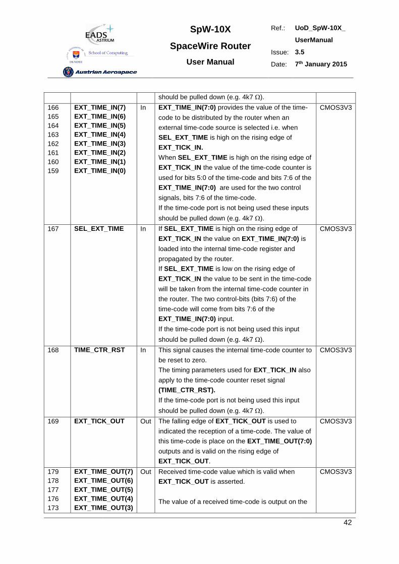
SpW-10X
SpaceWire Router
User Manual
Ref.: UoD_SpW-10X_
UserManual
Issue: 3.5
Date: 7th January 2015
42
should be pulled down (e.g. 4k7 ).
166
165
164
163
162
161
160
159
EXT_TIME_IN(7)
EXT_TIME_IN(6)
EXT_TIME_IN(5)
EXT_TIME_IN(4)
EXT_TIME_IN(3)
EXT_TIME_IN(2)
EXT_TIME_IN(1)
EXT_TIME_IN(0)
In EXT_TIME_IN(7:0) provides the value of the time-
code to be distributed by the router when an
external time-code source is selected i.e. when
SEL_EXT_TIME is high on the rising edge of
EXT_TICK_IN.
When SEL_EXT_TIME is high on the rising edge of
EXT_TICK_IN the value of the time-code counter is
used for bits 5:0 of the time-code and bits 7:6 of the
EXT_TIME_IN(7:0) are used for the two control
signals, bits 7:6 of the time-code.
If the time-code port is not being used these inputs
should be pulled down (e.g. 4k7 ).
CMOS3V3
167 SEL_EXT_TIME In If SEL_EXT_TIME is high on the rising edge of
EXT_TICK_IN the value on EXT_TIME_IN(7:0) is
loaded into the internal time-code register and
propagated by the router.
If SEL_EXT_TIME is low on the rising edge of
EXT_TICK_IN the value to be sent in the time-code
will be taken from the internal time-code counter in
the router. The two control-bits (bits 7:6) of the
time-code will come from bits 7:6 of the
EXT_TIME_IN(7:0) input.
If the time-code port is not being used this input
should be pulled down (e.g. 4k7 ).
CMOS3V3
168 TIME_CTR_RST In This signal causes the internal time-code counter to
be reset to zero.
The timing parameters used for EXT_TICK_IN also
apply to the time-code counter reset signal
(TIME_CTR_RST).
If the time-code port is not being used this input
should be pulled down (e.g. 4k7 ).
CMOS3V3
169 EXT_TICK_OUT Out The falling edge of EXT_TICK_OUT is used to
indicated the reception of a time-code. The value of
this time-code is place on the EXT_TIME_OUT(7:0)
outputs and is valid on the rising edge of
EXT_TICK_OUT.
CMOS3V3
179
178
177
176
173
EXT_TIME_OUT(7)
EXT_TIME_OUT(6)
EXT_TIME_OUT(5)
EXT_TIME_OUT(4)
EXT_TIME_OUT(3)
Out Received time-code value which is valid when
EXT_TICK_OUT is asserted.
The value of a received time-code is output on the
CMOS3V3
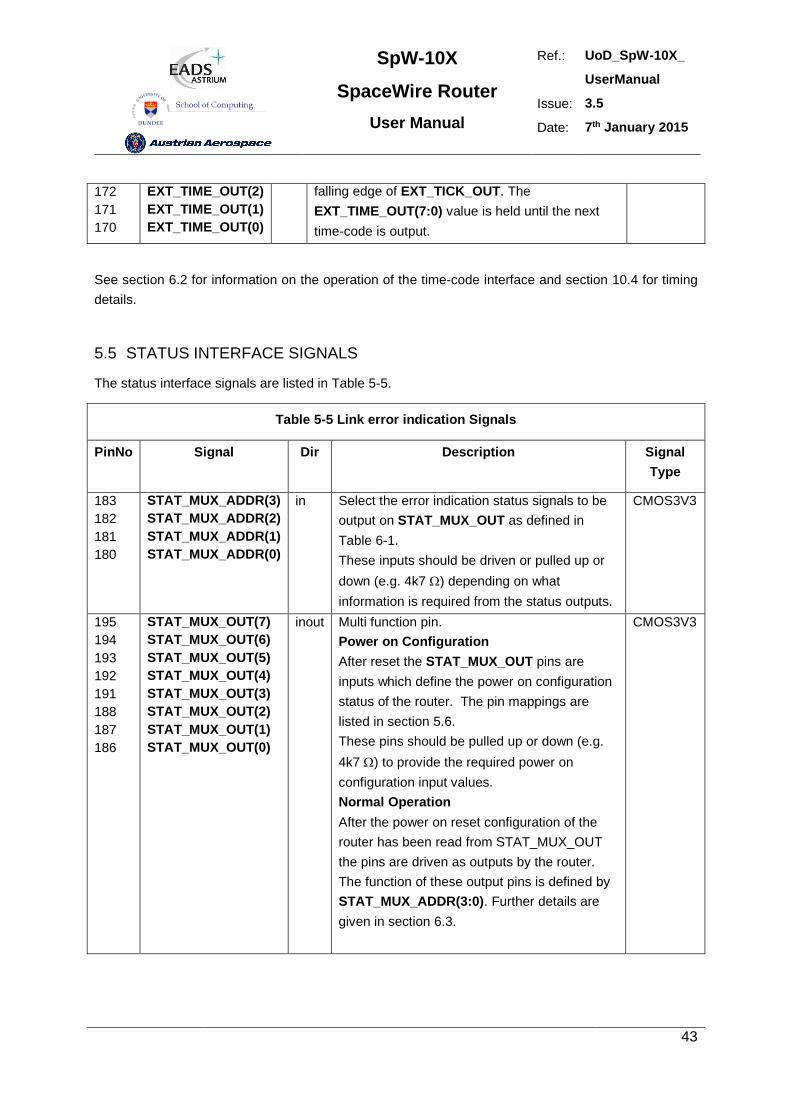
SpW-10X
SpaceWire Router
User Manual
Ref.: UoD_SpW-10X_
UserManual
Issue: 3.5
Date: 7th January 2015
43
172
171
170
EXT_TIME_OUT(2)
EXT_TIME_OUT(1)
EXT_TIME_OUT(0)
falling edge of EXT_TICK_OUT. The
EXT_TIME_OUT(7:0) value is held until the next
time-code is output.
See section 6.2 for information on the operation of the time-code interface and section 10.4 for timing
details.
5.5 STATUS INTERFACE SIGNALS
The status interface signals are listed in Table 5-5.
Table 5-5 Link error indication Signals
PinNo Signal Dir Description Signal
Type
183
182
181
180
STAT_MUX_ADDR(3)
STAT_MUX_ADDR(2)
STAT_MUX_ADDR(1)
STAT_MUX_ADDR(0)
in Select the error indication status signals to be
output on STAT_MUX_OUT as defined in
Table 6-1.
These inputs should be driven or pulled up or
down (e.g. 4k7 ) depending on what
information is required from the status outputs.
CMOS3V3
195
194
193
192
191
188
187
186
STAT_MUX_OUT(7)
STAT_MUX_OUT(6)
STAT_MUX_OUT(5)
STAT_MUX_OUT(4)
STAT_MUX_OUT(3)
STAT_MUX_OUT(2)
STAT_MUX_OUT(1)
STAT_MUX_OUT(0)
inout Multi function pin.
Power on Configuration
After reset the STAT_MUX_OUT pins are
inputs which define the power on configuration
status of the router. The pin mappings are
listed in section 5.6.
These pins should be pulled up or down (e.g.
4k7 ) to provide the required power on
configuration input values.
Normal Operation
After the power on reset configuration of the
router has been read from STAT_MUX_OUT
the pins are driven as outputs by the router.
The function of these output pins is defined by
STAT_MUX_ADDR(3:0). Further details are
given in section 6.3.
CMOS3V3
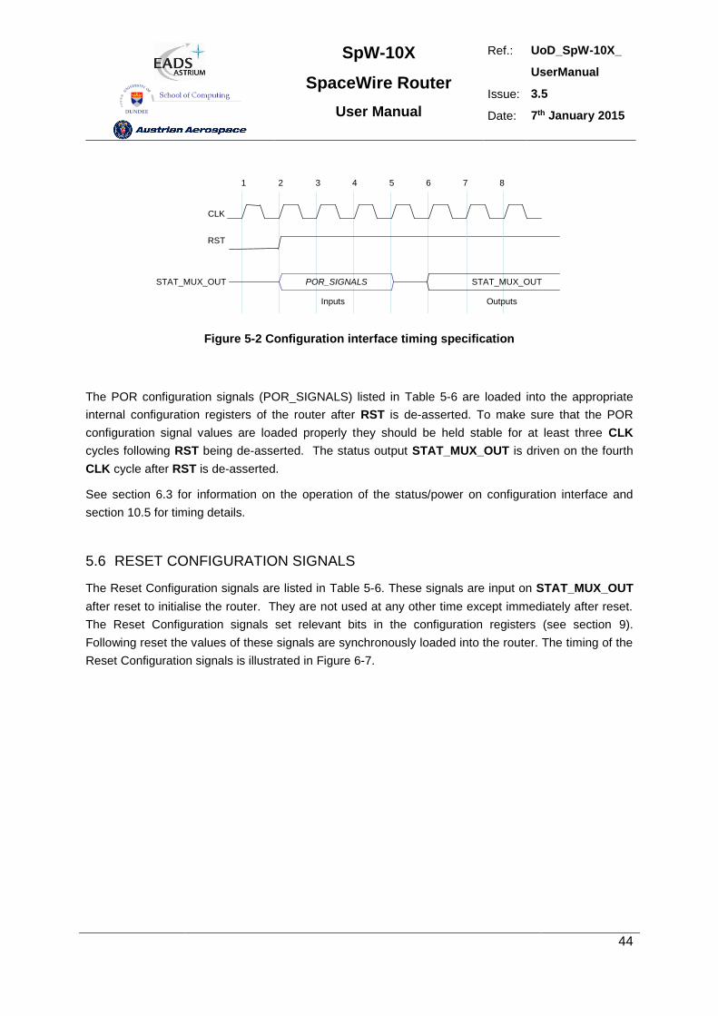
SpW-10X
SpaceWire Router
User Manual
Ref.: UoD_SpW-10X_
UserManual
Issue: 3.5
Date: 7th January 2015
44
CLK
RST
STAT_MUX_OUT POR_SIGNALS
1 2 3 4 5 6 7 8
STAT_MUX_OUT
Inputs Outputs
Figure 5-2 Configuration interface timing specification
The POR configuration signals (POR_SIGNALS) listed in Table 5-6 are loaded into the appropriate
internal configuration registers of the router after RST is de-asserted. To make sure that the POR
configuration signal values are loaded properly they should be held stable for at least three CLK
cycles following RST being de-asserted. The status output STAT_MUX_OUT is driven on the fourth
CLK cycle after RST is de-asserted.
See section 6.3 for information on the operation of the status/power on configuration interface and
section 10.5 for timing details.
5.6 RESET CONFIGURATION SIGNALS
The Reset Configuration signals are listed in Table 5-6. These signals are input on STAT_MUX_OUT
after reset to initialise the router. They are not used at any other time except immediately after reset.
The Reset Configuration signals set relevant bits in the configuration registers (see section 9).
Following reset the values of these signals are synchronously loaded into the router. The timing of the
Reset Configuration signals is illustrated in Figure 6-7.
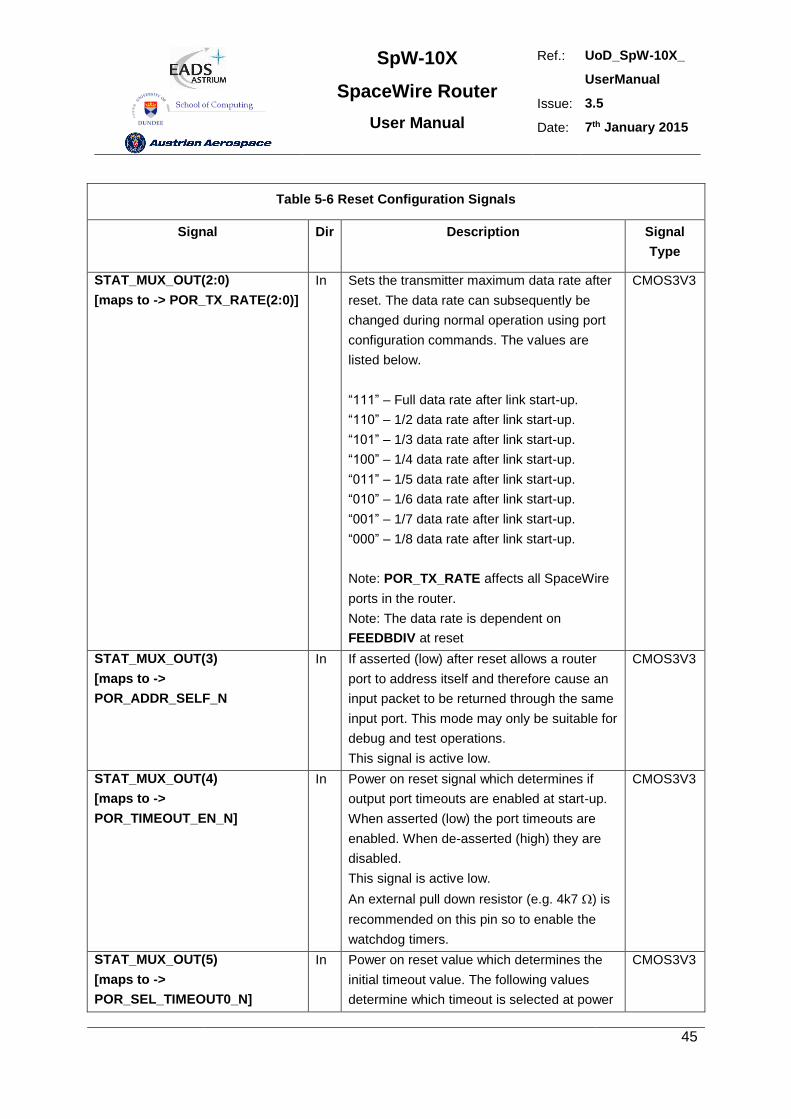
SpW-10X
SpaceWire Router
User Manual
Ref.: UoD_SpW-10X_
UserManual
Issue: 3.5
Date: 7th January 2015
45
Table 5-6 Reset Configuration Signals
Signal Dir Description Signal
Type
STAT_MUX_OUT(2:0)
[maps to -> POR_TX_RATE(2:0)]
In Sets the transmitter maximum data rate after
reset. The data rate can subsequently be
changed during normal operation using port
configuration commands. The values are
listed below.
“111” – Full data rate after link start-up.
“110” – 1/2 data rate after link start-up.
“101” – 1/3 data rate after link start-up.
“100” – 1/4 data rate after link start-up.
“011” – 1/5 data rate after link start-up.
“010” – 1/6 data rate after link start-up.
“001” – 1/7 data rate after link start-up.
“000” – 1/8 data rate after link start-up.
Note: POR_TX_RATE affects all SpaceWire
ports in the router.
Note: The data rate is dependent on
FEEDBDIV at reset
CMOS3V3
STAT_MUX_OUT(3)
[maps to ->
POR_ADDR_SELF_N
In If asserted (low) after reset allows a router
port to address itself and therefore cause an
input packet to be returned through the same
input port. This mode may only be suitable for
debug and test operations.
This signal is active low.
CMOS3V3
STAT_MUX_OUT(4)
[maps to ->
POR_TIMEOUT_EN_N]
In Power on reset signal which determines if
output port timeouts are enabled at start-up.
When asserted (low) the port timeouts are
enabled. When de-asserted (high) they are
disabled.
This signal is active low.
An external pull down resistor (e.g. 4k7 ) is
recommended on this pin so to enable the
watchdog timers.
CMOS3V3
STAT_MUX_OUT(5)
[maps to ->
POR_SEL_TIMEOUT0_N]
In Power on reset value which determines the
initial timeout value. The following values
determine which timeout is selected at power
CMOS3V3
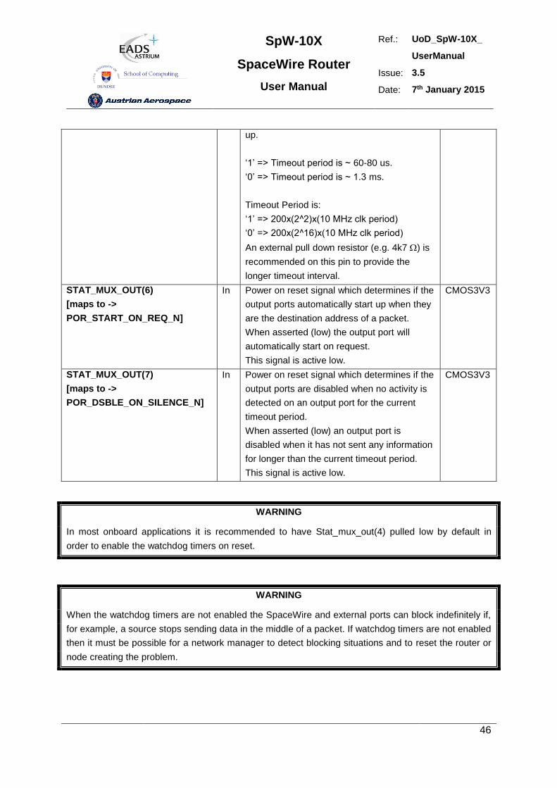
SpW-10X
SpaceWire Router
User Manual
Ref.: UoD_SpW-10X_
UserManual
Issue: 3.5
Date: 7th January 2015
46
up.
‘1’ => Timeout period is ~ 60-80 us.
‘0’ => Timeout period is ~ 1.3 ms.
Timeout Period is:
‘1’ => 200x(2^2)x(10 MHz clk period)
‘0’ => 200x(2^16)x(10 MHz clk period)
An external pull down resistor (e.g. 4k7 ) is
recommended on this pin to provide the
longer timeout interval.
STAT_MUX_OUT(6)
[maps to ->
POR_START_ON_REQ_N]
In Power on reset signal which determines if the
output ports automatically start up when they
are the destination address of a packet.
When asserted (low) the output port will
automatically start on request.
This signal is active low.
CMOS3V3
STAT_MUX_OUT(7)
[maps to ->
POR_DSBLE_ON_SILENCE_N]
In Power on reset signal which determines if the
output ports are disabled when no activity is
detected on an output port for the current
timeout period.
When asserted (low) an output port is
disabled when it has not sent any information
for longer than the current timeout period.
This signal is active low.
CMOS3V3
WARNING
In most onboard applications it is recommended to have Stat_mux_out(4) pulled low by default in
order to enable the watchdog timers on reset.
WARNING
When the watchdog timers are not enabled the SpaceWire and external ports can block indefinitely if,
for example, a source stops sending data in the middle of a packet. If watchdog timers are not enabled
then it must be possible for a network manager to detect blocking situations and to reset the router or
node creating the problem.
SpW-10X
SpaceWire Router
User Manual
Ref.: UoD_SpW-10X_
UserManual
Issue: 3.5
Date: 7th January 2015
47
Note: The recommended method for setting the POR signals is to use external pull up/down resistors
(e.g. 4k7 ) in which case the timing of the POR signals is not critical.
See section 6.3 and 6.4 for further information on the operation of the status/ power on configuration
interface and section 10.5 for timing details.
5.7 POWER, GROUND, PLL AND LVDS SIGNALS
5.7.1 General
The Power, Ground and special signal connections are listed in Table 5-7.
Table 5-7 Power, Ground and Special Signals
Signal Dir Description Signal
Type
Power - 3.3 V power for the device 3V3
Ground - Ground connection for the device GND
VCOBias PLL VCO Bias analogue
VSSPLL PLL Supply 3V3
VDDPLL PLL Supply GND
LoopFilter PLL Loop Filter analogue
LVDSref LVDS Buffer reference analogue
5.7.2 Decoupling
The power pins should be decoupled to the ground plane. One 100 nF decoupling capacitor should be
used for each power pin.
5.7.3 LVDS Reference
An external resistor is required to provide a reference for the LVDS buffers. A resistor with a value
between 16.3 k and 16.7 k must be connected between LVDSref and ground.
5.7.4 PLL External Components
An internal PLL is used to provide the base transmit clock signal for the SpaceWire interfaces from the
CLK input. External components are required to implement the PLL loop filter and to provide a bias for
the PLL VCO. These components are illustrated in Figure 5-3. Note that RVCO, C and C0 are all
connected to a quiet common ground track.
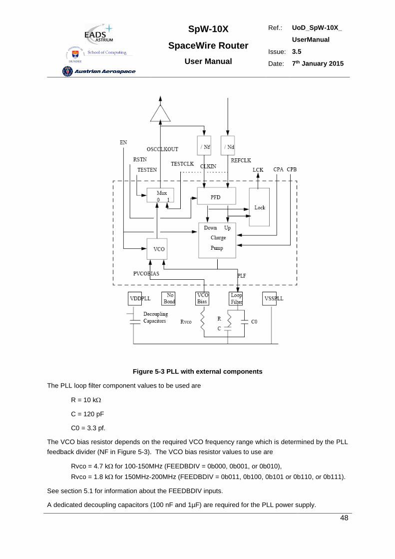
SpW-10X
SpaceWire Router
User Manual
Ref.: UoD_SpW-10X_
UserManual
Issue: 3.5
Date: 7th January 2015
48
Figure 5-3 PLL with external components
The PLL loop filter component values to be used are
R = 10 k
C = 120 pF
C0 = 3.3 pf.
The VCO bias resistor depends on the required VCO frequency range which is determined by the PLL
feedback divider (NF in Figure 5-3). The VCO bias resistor values to use are
Rvco = 4.7 kfor 100-150MHz (FEEDBDIV = 0b000, 0b001, or 0b010),
Rvco = 1.8 kfor 150MHz-200MHz (FEEDBDIV = 0b011, 0b100, 0b101 or 0b110, or 0b111).
See section 5.1 for information about the FEEDBDIV inputs.
A dedicated decoupling capacitors (100 nF and 1µF) are required for the PLL power supply.
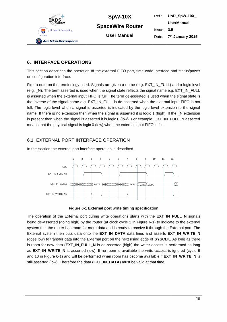
SpW-10X
SpaceWire Router
User Manual
Ref.: UoD_SpW-10X_
UserManual
Issue: 3.5
Date: 7th January 2015
49
6. INTERFACE OPERATIONS
This section describes the operation of the external FIFO port, time-code interface and status/power
on configuration interface.
First a note on the terminology used: Signals are given a name (e.g. EXT_IN_FULL) and a logic level
(e.g. _N). The term asserted is used when the signal state reflects the signal name e.g. EXT_IN_FULL
is asserted when the external input FIFO is full. The term de-asserted is used when the signal state is
the inverse of the signal name e.g. EXT_IN_FULL is de-asserted when the external input FIFO is not
full. The logic level when a signal is asserted is indicated by the logic level extension to the signal
name. If there is no extension then when the signal is asserted it is logic 1 (high). If the _N extension
is present then when the signal is asserted it is logic 0 (low). For example, EXT_IN_FULL_N asserted
means that the physical signal is logic 0 (low) when the external input FIFO is full.
6.1 EXTERNAL PORT INTERFACE OPERATION
In this section the external port interface operation is described.
CLK
1 2 3 4 5 6 7 8 9 10 11 12
EXT_IN_FULL_Nx
EXT_IN_DATAx
EXT_IN_WRITE_Nx
DATA EOP DATA DATA
writewrite write write
Figure 6-1 External port write timing specification
The operation of the External port during write operations starts with the EXT_IN_FULL_N signals
being de-asserted (going high) by the router (at clock cycle 2 in Figure 6-1) to indicate to the external
system that the router has room for more data and is ready to receive it through the External port. The
External system then puts data onto the EXT_IN_DATA data lines and asserts EXT_IN_WRITE_N
(goes low) to transfer data into the External port on the next rising edge of SYSCLK. As long as there
is room for new data (EXT_IN_FULL_N is de-asserted (high) the writer access is performed as long
as EXT_IN_WRITE_N is asserted (low). If no room is available the write access is ignored (cycle 9
and 10 in Figure 6-1) and will be performed when room has become available if EXT_IN_WRITE_N is
still asserted (low). Therefore the data (EXT_IN_DATA) must be valid at that time.
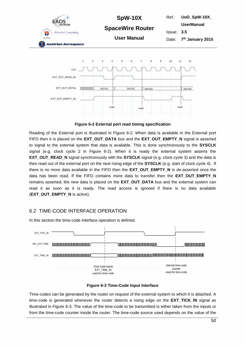
SpW-10X
SpaceWire Router
User Manual
Ref.: UoD_SpW-10X_
UserManual
Issue: 3.5
Date: 7th January 2015
50
CLK
1 2 3 4 5 6 7 8 9 10 11 12
EXT_OUT_READ_Nx
EXT_OUT_DATAx
EXT_OUT_EMPTY_Nx
DATA1 DATA2 DATA4DATA3
readread
read
Figure 6-2 External port read timing specification
Reading of the External port is illustrated in Figure 6-2. When data is available in the External port
FIFO then it is placed on the EXT_OUT_DATA bus and the EXT_OUT_EMPTY_N signal is asserted
to signal to the external system that data is available. This is done synchronously to the SYSCLK
signal (e.g. clock cycle 2 in Figure 6-2). When it is ready the external system asserts the
EXT_OUT_READ_N signal synchronously with the SYSCLK signal (e.g. clock cycle 3) and the data is
then read out of the external port on the next rising edge of the SYSCLK (e.g. start of clock cycle 4). If
there is no more data available in the FIFO then the EXT_OUT_EMPTY_N is de-asserted once the
data has been read. If the FIFO contains more data to transfer then the EXT_OUT_EMPTY_N
remains asserted, the new data is placed on the EXT_OUT_DATA bus and the external system can
read it as soon as it is ready. The read access is ignored if there is no data available
(EXT_OUT_EMPTY_N is active).
6.2 TIME-CODE INTERFACE OPERATION
In this section the time-code interface operation is defined.
EXT_TICK_IN
SEL_EXT_TIME
EXT_TIME_IN
Time-code inputs
EXT_TIME_IN
used for time-code
Internal time-code
counter
used for time-code
Figure 6-3 Time-Code Input Interface
Time-codes can be generated by the router on request of the external system to which it is attached. A
time-code is generated whenever the router detects a rising edge on the EXT_TICK_IN signal as
illustrated in Figure 6-3. The value of the time-code to be transmitted is either taken from the inputs or
from the time-code counter inside the router. The time-code source used depends on the value of the
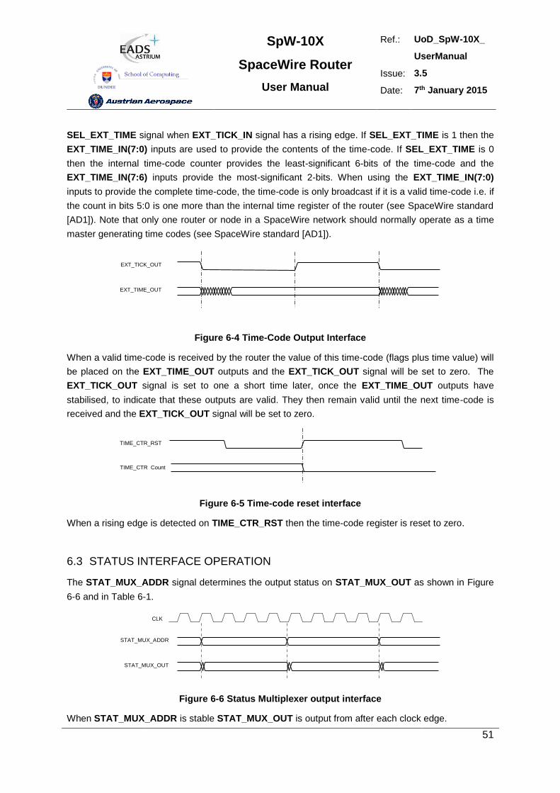
SpW-10X
SpaceWire Router
User Manual
Ref.: UoD_SpW-10X_
UserManual
Issue: 3.5
Date: 7th January 2015
51
SEL_EXT_TIME signal when EXT_TICK_IN signal has a rising edge. If SEL_EXT_TIME is 1 then the
EXT_TIME_IN(7:0) inputs are used to provide the contents of the time-code. If SEL_EXT_TIME is 0
then the internal time-code counter provides the least-significant 6-bits of the time-code and the
EXT_TIME_IN(7:6) inputs provide the most-significant 2-bits. When using the EXT_TIME_IN(7:0)
inputs to provide the complete time-code, the time-code is only broadcast if it is a valid time-code i.e. if
the count in bits 5:0 is one more than the internal time register of the router (see SpaceWire standard
[AD1]). Note that only one router or node in a SpaceWire network should normally operate as a time
master generating time codes (see SpaceWire standard [AD1]).
EXT_TICK_OUT
EXT_TIME_OUT
Figure 6-4 Time-Code Output Interface
When a valid time-code is received by the router the value of this time-code (flags plus time value) will
be placed on the EXT_TIME_OUT outputs and the EXT_TICK_OUT signal will be set to zero. The
EXT_TICK_OUT signal is set to one a short time later, once the EXT_TIME_OUT outputs have
stabilised, to indicate that these outputs are valid. They then remain valid until the next time-code is
received and the EXT_TICK_OUT signal will be set to zero.
TIME_CTR_RST
TIME_CTR Count
Figure 6-5 Time-code reset interface
When a rising edge is detected on TIME_CTR_RST then the time-code register is reset to zero.
6.3 STATUS INTERFACE OPERATION
The STAT_MUX_ADDR signal determines the output status on STAT_MUX_OUT as shown in Figure
6-6 and in Table 6-1.
STAT_MUX_ADDR
STAT_MUX_OUT
CLK
1 2 3 4 5 6 7 8 9 10 11 12
Figure 6-6 Status Multiplexer output interface
When STAT_MUX_ADDR is stable STAT_MUX_OUT is output from after each clock edge.
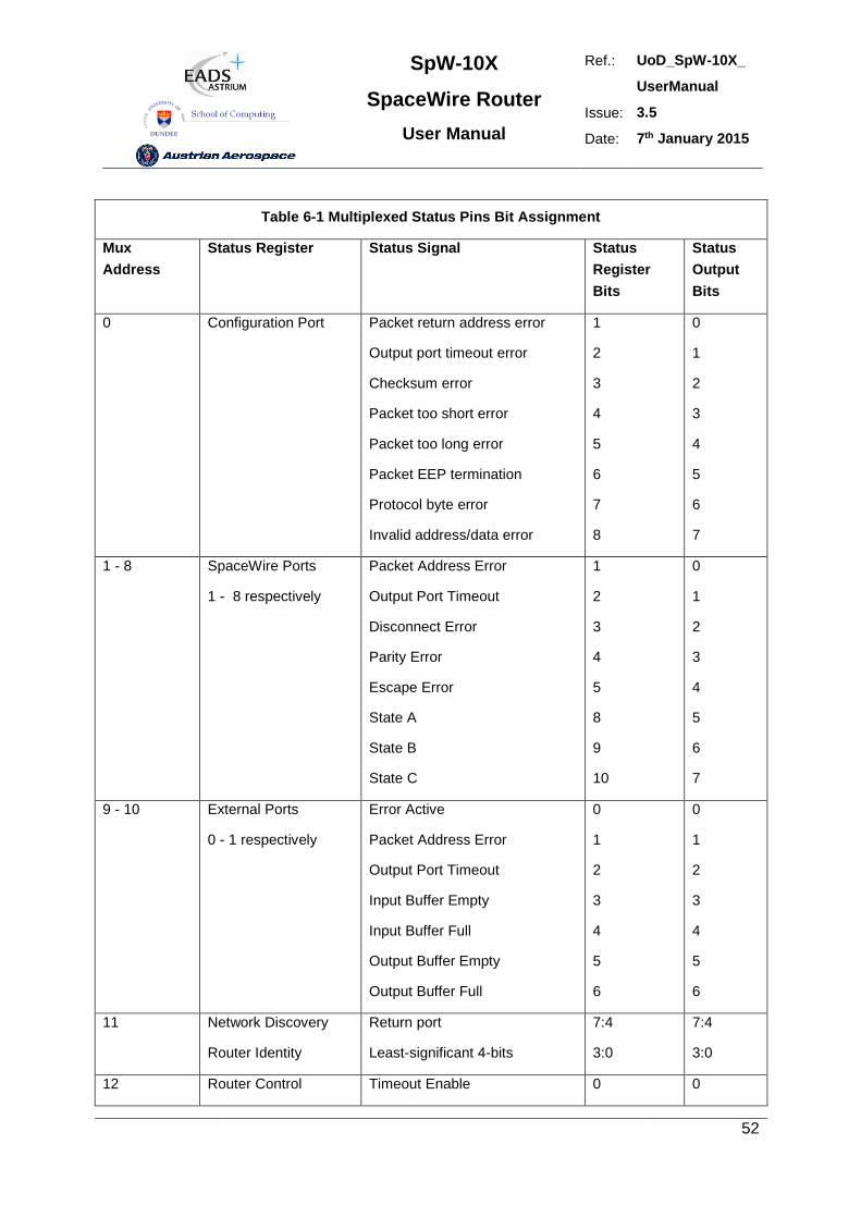
SpW-10X
SpaceWire Router
User Manual
Ref.: UoD_SpW-10X_
UserManual
Issue: 3.5
Date: 7th January 2015
52
Table 6-1 Multiplexed Status Pins Bit Assignment
Mux
Address
Status Register Status Signal Status
Register
Bits
Status
Output
Bits
0 Configuration Port Packet return address error
Output port timeout error
Checksum error
Packet too short error
Packet too long error
Packet EEP termination
Protocol byte error
Invalid address/data error
1
2
3
4
5
6
7
8
0
1
2
3
4
5
6
7
1 - 8 SpaceWire Ports
1 - 8 respectively
Packet Address Error
Output Port Timeout
Disconnect Error
Parity Error
Escape Error
State A
State B
State C
1
2
3
4
5
8
9
10
0
1
2
3
4
5
6
7
9 - 10 External Ports
0 - 1 respectively
Error Active
Packet Address Error
Output Port Timeout
Input Buffer Empty
Input Buffer Full
Output Buffer Empty
Output Buffer Full
0
1
2
3
4
5
6
0
1
2
3
4
5
6
11 Network Discovery
Router Identity
Return port
Least-significant 4-bits
7:4
3:0
7:4
3:0
12 Router Control Timeout Enable 0 0
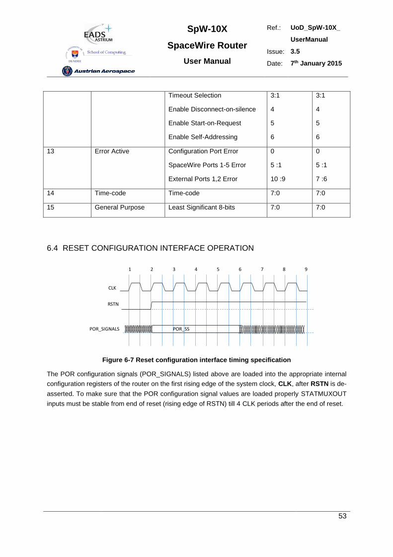
SpW-10X
SpaceWire Router
User Manual
Ref.: UoD_SpW-10X_
UserManual
Issue: 3.5
Date: 7th January 2015
53
Timeout Selection
Enable Disconnect-on-silence
Enable Start-on-Request
Enable Self-Addressing
3:1
4
5
6
3:1
4
5
6
13 Error Active Configuration Port Error
SpaceWire Ports 1-5 Error
External Ports 1,2 Error
0
5 :1
10 :9
0
5 :1
7 :6
14 Time-code Time-code 7:0 7:0
15 General Purpose Least Significant 8-bits 7:0 7:0
6.4 RESET CONFIGURATION INTERFACE OPERATION
CLK
RSTN
POR_SIGNALS POR_SS
1 2 3 4 5 6 7 8 9
Figure 6-7 Reset configuration interface timing specification
The POR configuration signals (POR_SIGNALS) listed above are loaded into the appropriate internal
configuration registers of the router on the first rising edge of the system clock, CLK, after RSTN is de-
asserted. To make sure that the POR configuration signal values are loaded properly STATMUXOUT
inputs must be stable from end of reset (rising edge of RSTN) till 4 CLK periods after the end of reset.
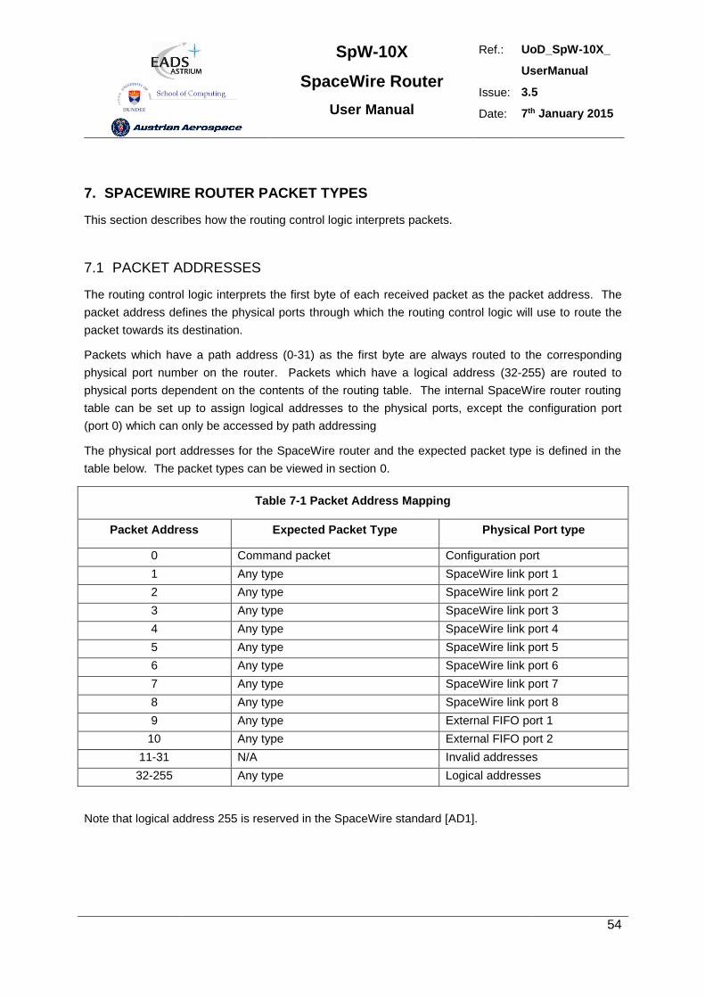
SpW-10X
SpaceWire Router
User Manual
Ref.: UoD_SpW-10X_
UserManual
Issue: 3.5
Date: 7th January 2015
54
7. SPACEWIRE ROUTER PACKET TYPES
This section describes how the routing control logic interprets packets.
7.1 PACKET ADDRESSES
The routing control logic interprets the first byte of each received packet as the packet address. The
packet address defines the physical ports through which the routing control logic will use to route the
packet towards its destination.
Packets which have a path address (0-31) as the first byte are always routed to the corresponding
physical port number on the router. Packets which have a logical address (32-255) are routed to
physical ports dependent on the contents of the routing table. The internal SpaceWire router routing
table can be set up to assign logical addresses to the physical ports, except the configuration port
(port 0) which can only be accessed by path addressing
The physical port addresses for the SpaceWire router and the expected packet type is defined in the
table below. The packet types can be viewed in section 0.
Table 7-1 Packet Address Mapping
Packet Address Expected Packet Type Physical Port type
0 Command packet Configuration port
1 Any type SpaceWire link port 1
2 Any type SpaceWire link port 2
3 Any type SpaceWire link port 3
4 Any type SpaceWire link port 4
5 Any type SpaceWire link port 5
6 Any type SpaceWire link port 6
7 Any type SpaceWire link port 7
8 Any type SpaceWire link port 8
9 Any type External FIFO port 1
10 Any type External FIFO port 2
11-31 N/A Invalid addresses
32-255 Any type Logical addresses
Note that logical address 255 is reserved in the SpaceWire standard [AD1].
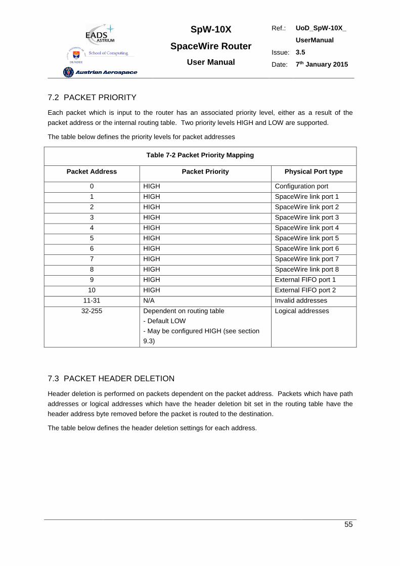
SpW-10X
SpaceWire Router
User Manual
Ref.: UoD_SpW-10X_
UserManual
Issue: 3.5
Date: 7th January 2015
55
7.2 PACKET PRIORITY
Each packet which is input to the router has an associated priority level, either as a result of the
packet address or the internal routing table. Two priority levels HIGH and LOW are supported.
The table below defines the priority levels for packet addresses
Table 7-2 Packet Priority Mapping
Packet Address Packet Priority Physical Port type
0 HIGH Configuration port
1 HIGH SpaceWire link port 1
2 HIGH SpaceWire link port 2
3 HIGH SpaceWire link port 3
4 HIGH SpaceWire link port 4
5 HIGH SpaceWire link port 5
6 HIGH SpaceWire link port 6
7 HIGH SpaceWire link port 7
8 HIGH SpaceWire link port 8
9 HIGH External FIFO port 1
10 HIGH External FIFO port 2
11-31 N/A Invalid addresses
32-255 Dependent on routing table
- Default LOW
- May be configured HIGH (see section
9.3)
Logical addresses
7.3 PACKET HEADER DELETION
Header deletion is performed on packets dependent on the packet address. Packets which have path
addresses or logical addresses which have the header deletion bit set in the routing table have the
header address byte removed before the packet is routed to the destination.
The table below defines the header deletion settings for each address.
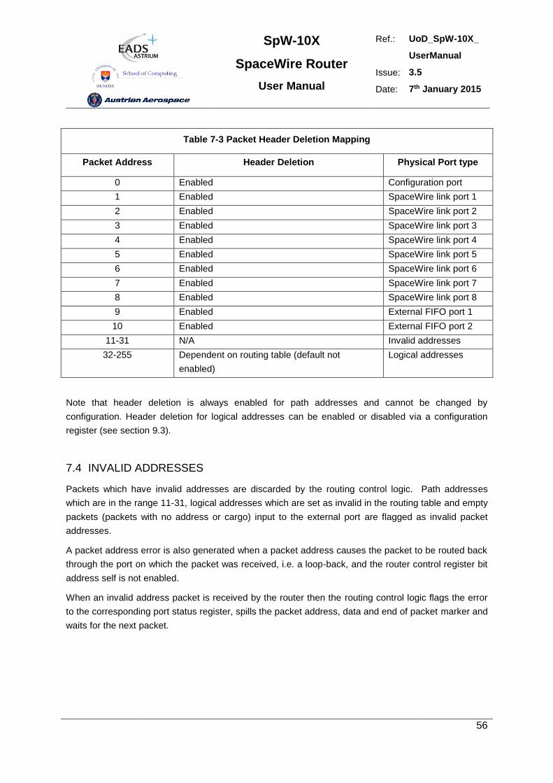
SpW-10X
SpaceWire Router
User Manual
Ref.: UoD_SpW-10X_
UserManual
Issue: 3.5
Date: 7th January 2015
56
Table 7-3 Packet Header Deletion Mapping
Packet Address Header Deletion Physical Port type
0 Enabled Configuration port
1 Enabled SpaceWire link port 1
2 Enabled SpaceWire link port 2
3 Enabled SpaceWire link port 3
4 Enabled SpaceWire link port 4
5 Enabled SpaceWire link port 5
6 Enabled SpaceWire link port 6
7 Enabled SpaceWire link port 7
8 Enabled SpaceWire link port 8
9 Enabled External FIFO port 1
10 Enabled External FIFO port 2
11-31 N/A Invalid addresses
32-255 Dependent on routing table (default not
enabled)
Logical addresses
Note that header deletion is always enabled for path addresses and cannot be changed by
configuration. Header deletion for logical addresses can be enabled or disabled via a configuration
register (see section 9.3).
7.4 INVALID ADDRESSES
Packets which have invalid addresses are discarded by the routing control logic. Path addresses
which are in the range 11-31, logical addresses which are set as invalid in the routing table and empty
packets (packets with no address or cargo) input to the external port are flagged as invalid packet
addresses.
A packet address error is also generated when a packet address causes the packet to be routed back
through the port on which the packet was received, i.e. a loop-back, and the router control register bit
address self is not enabled.
When an invalid address packet is received by the router then the routing control logic flags the error
to the corresponding port status register, spills the packet address, data and end of packet marker and
waits for the next packet.
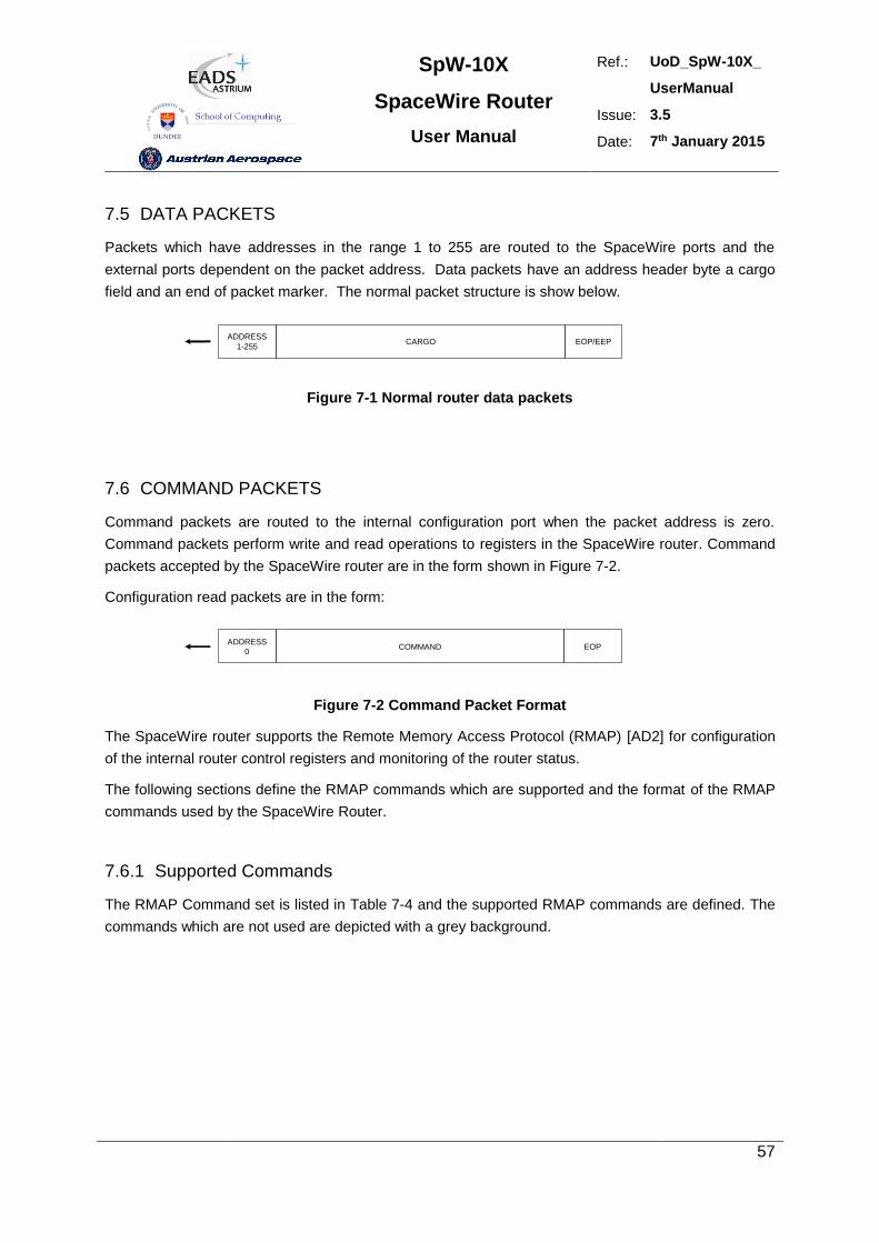
SpW-10X
SpaceWire Router
User Manual
Ref.: UoD_SpW-10X_
UserManual
Issue: 3.5
Date: 7th January 2015
57
7.5 DATA PACKETS
Packets which have addresses in the range 1 to 255 are routed to the SpaceWire ports and the
external ports dependent on the packet address. Data packets have an address header byte a cargo
field and an end of packet marker. The normal packet structure is show below.
ADDRESS
1-255CARGO EOP/EEP
Figure 7-1 Normal router data packets
7.6 COMMAND PACKETS
Command packets are routed to the internal configuration port when the packet address is zero.
Command packets perform write and read operations to registers in the SpaceWire router. Command
packets accepted by the SpaceWire router are in the form shown in Figure 7-2.
Configuration read packets are in the form:
ADDRESS
0COMMAND EOP
Figure 7-2 Command Packet Format
The SpaceWire router supports the Remote Memory Access Protocol (RMAP) [AD2] for configuration
of the internal router control registers and monitoring of the router status.
The following sections define the RMAP commands which are supported and the format of the RMAP
commands used by the SpaceWire Router.
7.6.1 Supported Commands
The RMAP Command set is listed in Table 7-4 and the supported RMAP commands are defined. The
commands which are not used are depicted with a grey background.
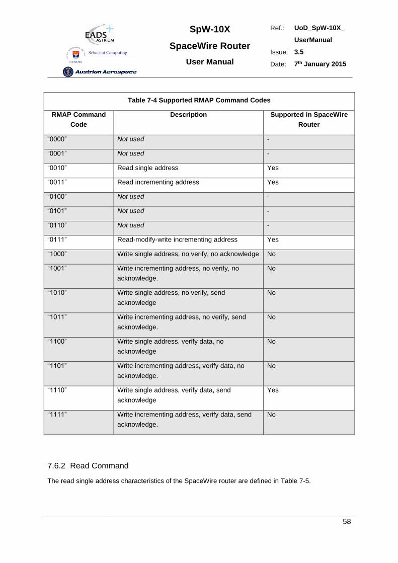
SpW-10X
SpaceWire Router
User Manual
Ref.: UoD_SpW-10X_
UserManual
Issue: 3.5
Date: 7th January 2015
58
Table 7-4 Supported RMAP Command Codes
RMAP Command
Code
Description Supported in SpaceWire
Router
“0000” Not used -
“0001” Not used -
“0010” Read single address Yes
“0011” Read incrementing address Yes
“0100” Not used -
“0101” Not used -
“0110” Not used -
“0111” Read-modify-write incrementing address Yes
“1000” Write single address, no verify, no acknowledge No
“1001” Write incrementing address, no verify, no
acknowledge.
No
“1010” Write single address, no verify, send
acknowledge
No
“1011” Write incrementing address, no verify, send
acknowledge.
No
“1100” Write single address, verify data, no
acknowledge
No
“1101” Write incrementing address, verify data, no
acknowledge.
No
“1110” Write single address, verify data, send
acknowledge
Yes
“1111” Write incrementing address, verify data, send
acknowledge.
No
7.6.2 Read Command
The read single address characteristics of the SpaceWire router are defined in Table 7-5.
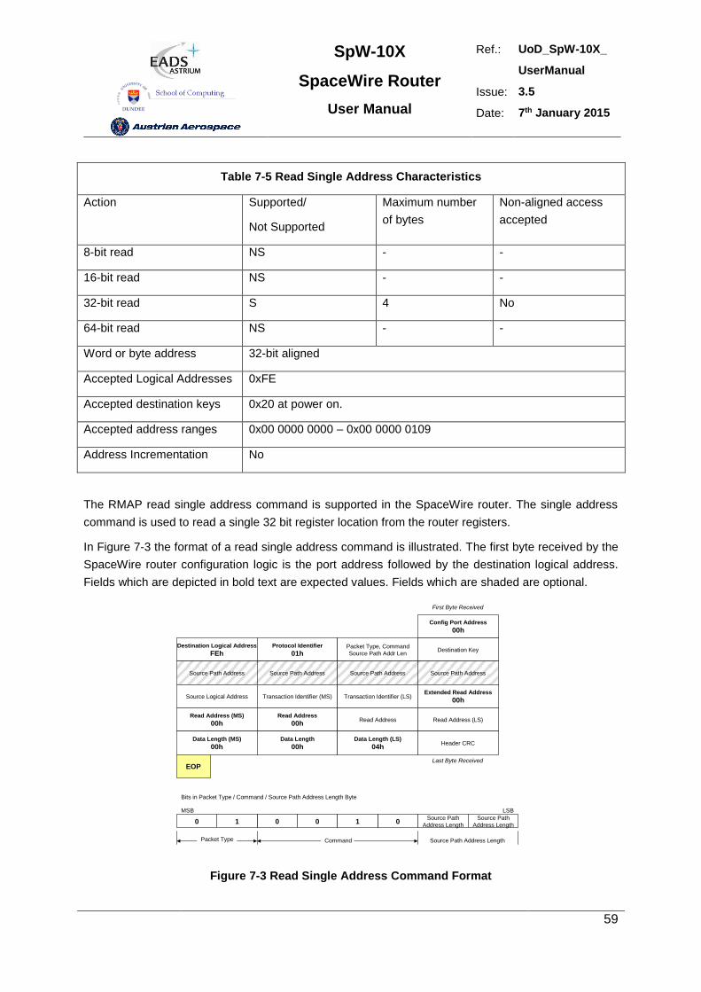
SpW-10X
SpaceWire Router
User Manual
Ref.: UoD_SpW-10X_
UserManual
Issue: 3.5
Date: 7th January 2015
59
Table 7-5 Read Single Address Characteristics
Action Supported/
Not Supported
Maximum number
of bytes
Non-aligned access
accepted
8-bit read NS - -
16-bit read NS - -
32-bit read S 4 No
64-bit read NS - -
Word or byte address 32-bit aligned
Accepted Logical Addresses 0xFE
Accepted destination keys 0x20 at power on.
Accepted address ranges 0x00 0000 0000 – 0x00 0000 0109
Address Incrementation No
The RMAP read single address command is supported in the SpaceWire router. The single address
command is used to read a single 32 bit register location from the router registers.
In Figure 7-3 the format of a read single address command is illustrated. The first byte received by the
SpaceWire router configuration logic is the port address followed by the destination logical address.
Fields which are depicted in bold text are expected values. Fields which are shaded are optional.
Read Address (MS)
00hRead Address
00hRead Address Read Address (LS)
Data Length (MS)
00hData Length
00hData Length (LS)
04hHeader CRC
Config Port Address
00h
EOPLast Byte Received
Destination Logical Address
FEhProtocol Identifier
01hPacket Type, Command
Source Path Addr LenDestination Key
Source Path Address Source Path Address Source Path Address Source Path Address
Source Logical Address Transaction Identifier (MS) Transaction Identifier (LS)Extended Read Address
00h
0 01 010
Bits in Packet Type / Command / Source Path Address Length Byte
MSB
Packet Type Command
Source Path
Address Length
Source Path
Address Length
LSB
Source Path Address Length
First Byte Received
Figure 7-3 Read Single Address Command Format
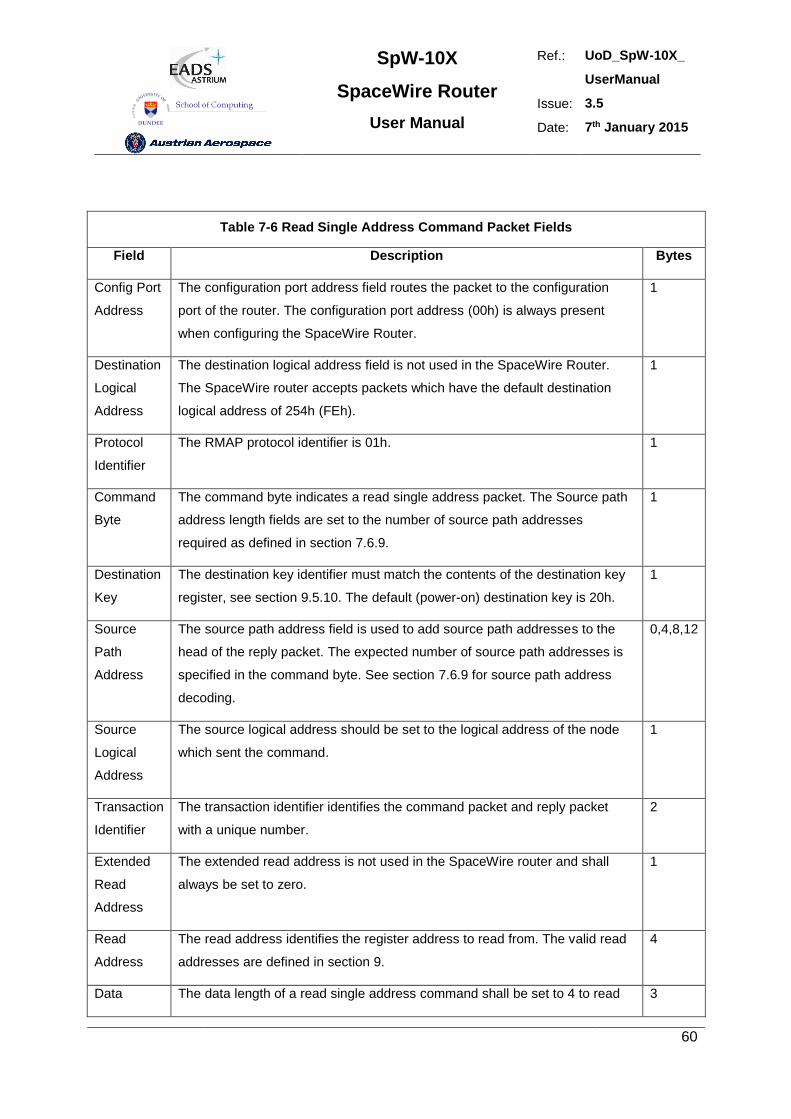
SpW-10X
SpaceWire Router
User Manual
Ref.: UoD_SpW-10X_
UserManual
Issue: 3.5
Date: 7th January 2015
60
Table 7-6 Read Single Address Command Packet Fields
Field Description Bytes
Config Port
Address
The configuration port address field routes the packet to the configuration
port of the router. The configuration port address (00h) is always present
when configuring the SpaceWire Router.
1
Destination
Logical
Address
The destination logical address field is not used in the SpaceWire Router.
The SpaceWire router accepts packets which have the default destination
logical address of 254h (FEh).
1
Protocol
Identifier
The RMAP protocol identifier is 01h. 1
Command
Byte
The command byte indicates a read single address packet. The Source path
address length fields are set to the number of source path addresses
required as defined in section 7.6.9.
1
Destination
Key
The destination key identifier must match the contents of the destination key
register, see section 9.5.10. The default (power-on) destination key is 20h.
1
Source
Path
Address
The source path address field is used to add source path addresses to the
head of the reply packet. The expected number of source path addresses is
specified in the command byte. See section 7.6.9 for source path address
decoding.
0,4,8,12
Source
Logical
Address
The source logical address should be set to the logical address of the node
which sent the command.
1
Transaction
Identifier
The transaction identifier identifies the command packet and reply packet
with a unique number.
2
Extended
Read
Address
The extended read address is not used in the SpaceWire router and shall
always be set to zero.
1
Read
Address
The read address identifies the register address to read from. The valid read
addresses are defined in section 9.
4
Data The data length of a read single address command shall be set to 4 to read 3
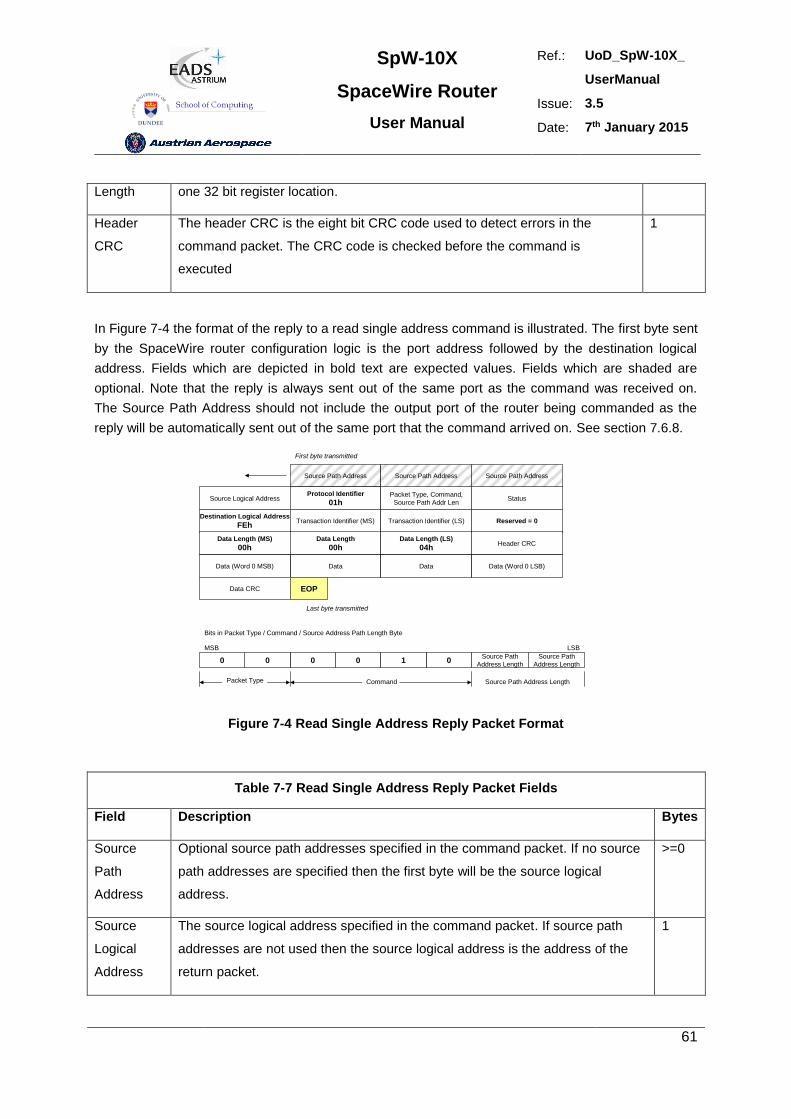
SpW-10X
SpaceWire Router
User Manual
Ref.: UoD_SpW-10X_
UserManual
Issue: 3.5
Date: 7th January 2015
61
Length one 32 bit register location.
Header
CRC
The header CRC is the eight bit CRC code used to detect errors in the
command packet. The CRC code is checked before the command is
executed
1
In Figure 7-4 the format of the reply to a read single address command is illustrated. The first byte sent
by the SpaceWire router configuration logic is the port address followed by the destination logical
address. Fields which are depicted in bold text are expected values. Fields which are shaded are
optional. Note that the reply is always sent out of the same port as the command was received on.
The Source Path Address should not include the output port of the router being commanded as the
reply will be automatically sent out of the same port that the command arrived on. See section 7.6.8.
Source Path Address
Source Logical AddressProtocol Identifier
01hPacket Type, Command,
Source Path Addr LenStatus
Destination Logical Address
FEhTransaction Identifier (MS) Transaction Identifier (LS) Reserved = 0
Data Length (MS)
00hData Length
00hData Length (LS)
04hHeader CRC
Data (Word 0 MSB) Data Data Data (Word 0 LSB)
Source Path Address Source Path Address
Data CRC EOP
First byte transmitted
Last byte transmitted
0 00 010
Bits in Packet Type / Command / Source Address Path Length Byte
MSB
Packet Type Command
Source Path
Address Length
Source Path
Address Length
LSB
Source Path Address Length
Figure 7-4 Read Single Address Reply Packet Format
Table 7-7 Read Single Address Reply Packet Fields
Field Description Bytes
Source
Path
Address
Optional source path addresses specified in the command packet. If no source
path addresses are specified then the first byte will be the source logical
address.
>=0
Source
Logical
Address
The source logical address specified in the command packet. If source path
addresses are not used then the source logical address is the address of the
return packet.
1
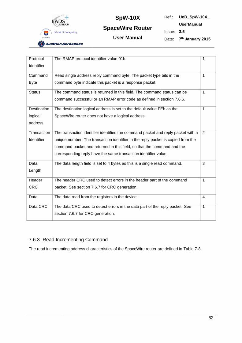
SpW-10X
SpaceWire Router
User Manual
Ref.: UoD_SpW-10X_
UserManual
Issue: 3.5
Date: 7th January 2015
62
Protocol
Identifier
The RMAP protocol identifier value 01h. 1
Command
Byte
Read single address reply command byte. The packet type bits in the
command byte indicate this packet is a response packet.
1
Status The command status is returned in this field. The command status can be
command successful or an RMAP error code as defined in section 7.6.6.
1
Destination
logical
address
The destination logical address is set to the default value FEh as the
SpaceWire router does not have a logical address.
1
Transaction
Identifier
The transaction identifier identifies the command packet and reply packet with a
unique number. The transaction identifier in the reply packet is copied from the
command packet and returned in this field, so that the command and the
corresponding reply have the same transaction identifier value.
2
Data
Length
The data length field is set to 4 bytes as this is a single read command. 3
Header
CRC
The header CRC used to detect errors in the header part of the command
packet. See section 7.6.7 for CRC generation.
1
Data The data read from the registers in the device. 4
Data CRC The data CRC used to detect errors in the data part of the reply packet. See
section 7.6.7 for CRC generation.
1
7.6.3 Read Incrementing Command
The read incrementing address characteristics of the SpaceWire router are defined in Table 7-8.
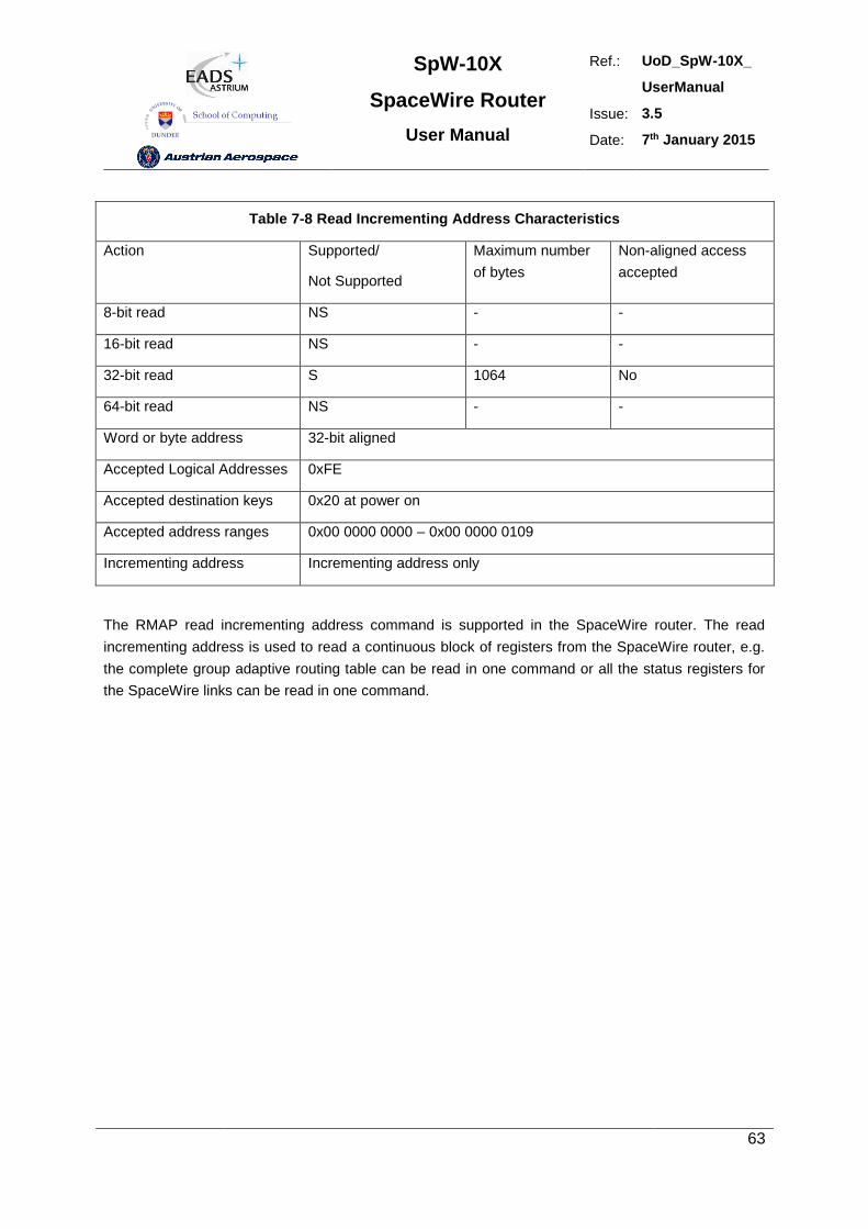
SpW-10X
SpaceWire Router
User Manual
Ref.: UoD_SpW-10X_
UserManual
Issue: 3.5
Date: 7th January 2015
63
Table 7-8 Read Incrementing Address Characteristics
Action Supported/
Not Supported
Maximum number
of bytes
Non-aligned access
accepted
8-bit read NS - -
16-bit read NS - -
32-bit read S 1064 No
64-bit read NS - -
Word or byte address 32-bit aligned
Accepted Logical Addresses 0xFE
Accepted destination keys 0x20 at power on
Accepted address ranges 0x00 0000 0000 – 0x00 0000 0109
Incrementing address Incrementing address only
The RMAP read incrementing address command is supported in the SpaceWire router. The read
incrementing address is used to read a continuous block of registers from the SpaceWire router, e.g.
the complete group adaptive routing table can be read in one command or all the status registers for
the SpaceWire links can be read in one command.
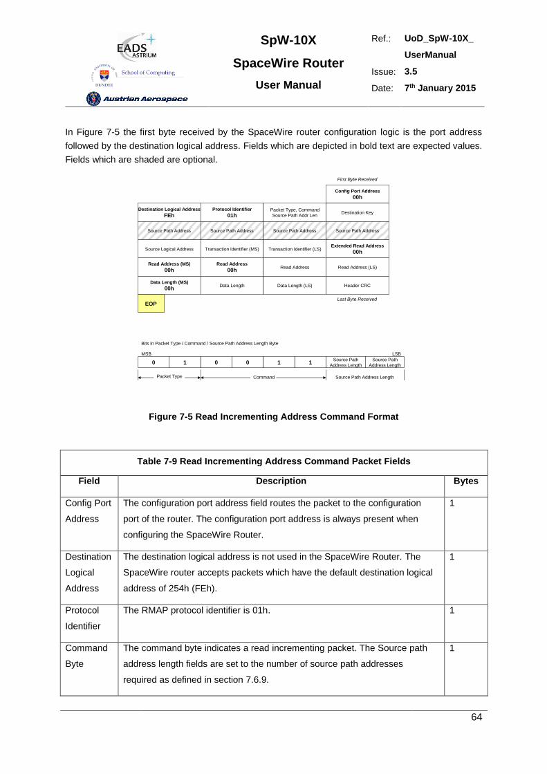
SpW-10X
SpaceWire Router
User Manual
Ref.: UoD_SpW-10X_
UserManual
Issue: 3.5
Date: 7th January 2015
64
In Figure 7-5 the first byte received by the SpaceWire router configuration logic is the port address
followed by the destination logical address. Fields which are depicted in bold text are expected values.
Fields which are shaded are optional.
Read Address (MS)
00hRead Address
00hRead Address Read Address (LS)
Data Length (MS)
00hData Length Data Length (LS) Header CRC
Config Port Address
00h
EOPLast Byte Received
Destination Logical Address
FEhProtocol Identifier
01hPacket Type, Command
Source Path Addr LenDestination Key
Source Path Address Source Path Address Source Path Address Source Path Address
Source Logical Address Transaction Identifier (MS) Transaction Identifier (LS)Extended Read Address
00h
0 01 110
Bits in Packet Type / Command / Source Path Address Length Byte
MSB
Packet Type Command
Source Path
Address Length
Source Path
Address Length
LSB
Source Path Address Length
First Byte Received
Figure 7-5 Read Incrementing Address Command Format
Table 7-9 Read Incrementing Address Command Packet Fields
Field Description Bytes
Config Port
Address
The configuration port address field routes the packet to the configuration
port of the router. The configuration port address is always present when
configuring the SpaceWire Router.
1
Destination
Logical
Address
The destination logical address is not used in the SpaceWire Router. The
SpaceWire router accepts packets which have the default destination logical
address of 254h (FEh).
1
Protocol
Identifier
The RMAP protocol identifier is 01h. 1
Command
Byte
The command byte indicates a read incrementing packet. The Source path
address length fields are set to the number of source path addresses
required as defined in section 7.6.9.
1
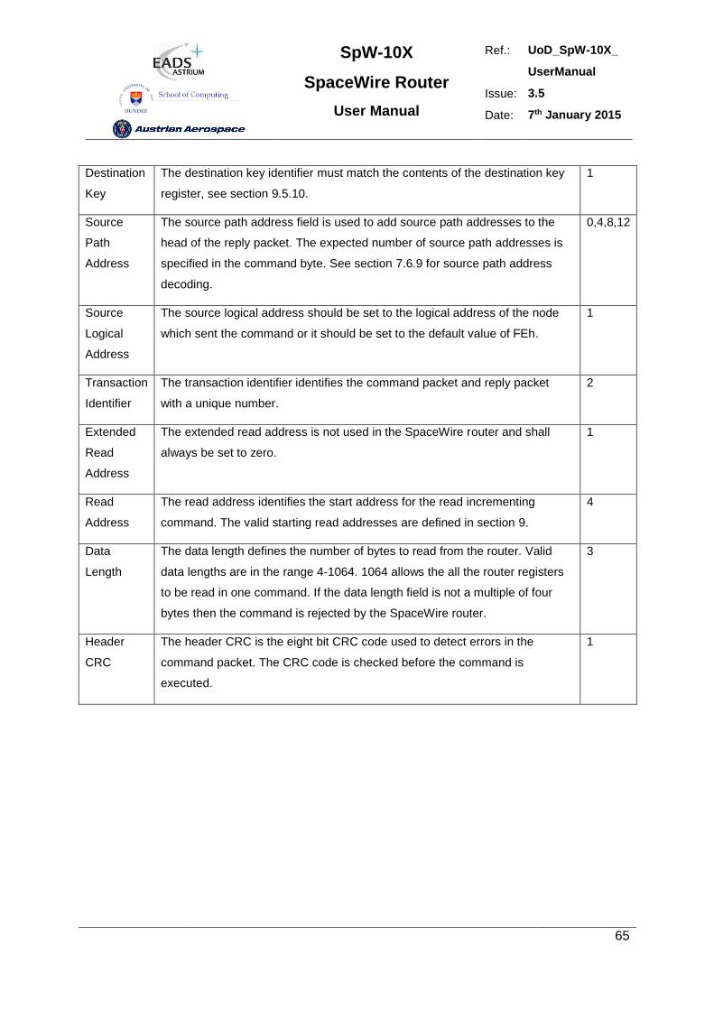
SpW-10X
SpaceWire Router
User Manual
Ref.: UoD_SpW-10X_
UserManual
Issue: 3.5
Date: 7th January 2015
65
Destination
Key
The destination key identifier must match the contents of the destination key
register, see section 9.5.10.
1
Source
Path
Address
The source path address field is used to add source path addresses to the
head of the reply packet. The expected number of source path addresses is
specified in the command byte. See section 7.6.9 for source path address
decoding.
0,4,8,12
Source
Logical
Address
The source logical address should be set to the logical address of the node
which sent the command or it should be set to the default value of FEh.
1
Transaction
Identifier
The transaction identifier identifies the command packet and reply packet
with a unique number.
2
Extended
Read
Address
The extended read address is not used in the SpaceWire router and shall
always be set to zero.
1
Read
Address
The read address identifies the start address for the read incrementing
command. The valid starting read addresses are defined in section 9.
4
Data
Length
The data length defines the number of bytes to read from the router. Valid
data lengths are in the range 4-1064. 1064 allows the all the router registers
to be read in one command. If the data length field is not a multiple of four
bytes then the command is rejected by the SpaceWire router.
3
Header
CRC
The header CRC is the eight bit CRC code used to detect errors in the
command packet. The CRC code is checked before the command is
executed.
1
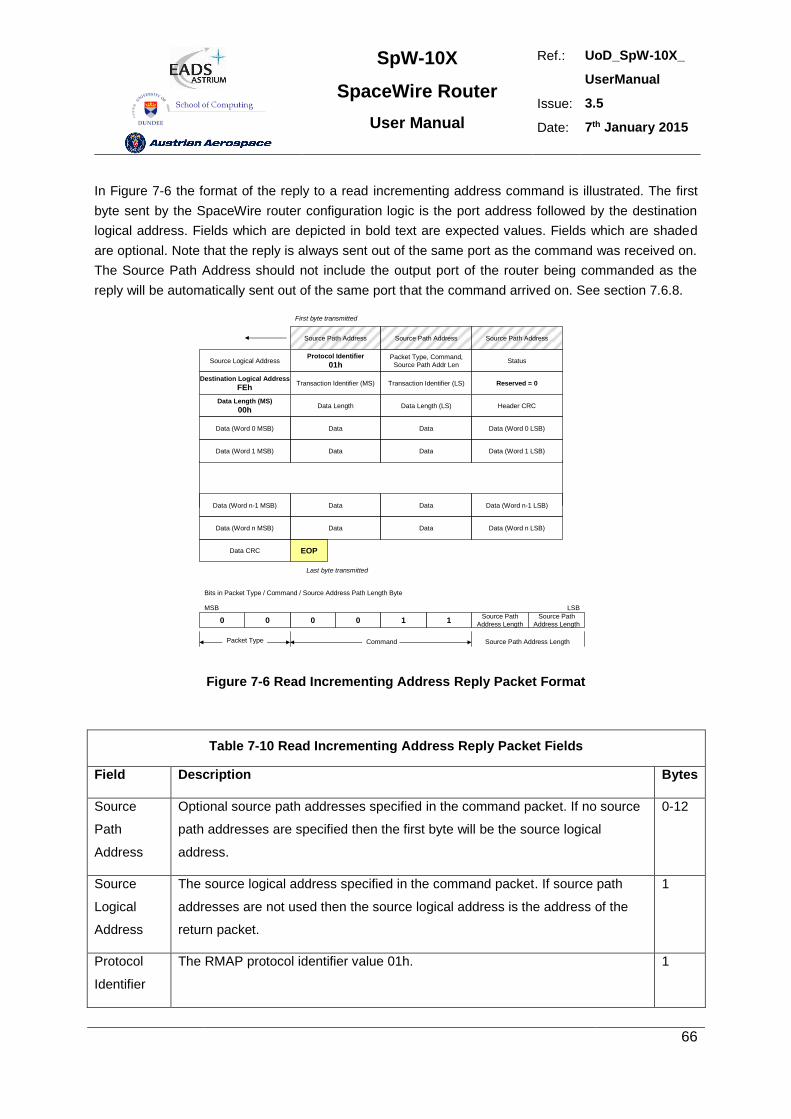
SpW-10X
SpaceWire Router
User Manual
Ref.: UoD_SpW-10X_
UserManual
Issue: 3.5
Date: 7th January 2015
66
In Figure 7-6 the format of the reply to a read incrementing address command is illustrated. The first
byte sent by the SpaceWire router configuration logic is the port address followed by the destination
logical address. Fields which are depicted in bold text are expected values. Fields which are shaded
are optional. Note that the reply is always sent out of the same port as the command was received on.
The Source Path Address should not include the output port of the router being commanded as the
reply will be automatically sent out of the same port that the command arrived on. See section 7.6.8.
Source Path Address
Source Logical AddressProtocol Identifier
01hPacket Type, Command,
Source Path Addr LenStatus
Destination Logical Address
FEhTransaction Identifier (MS) Transaction Identifier (LS) Reserved = 0
Data Length (MS)
00hData Length Data Length (LS) Header CRC
Data (Word 0 MSB) Data Data Data (Word 0 LSB)
Source Path Address Source Path Address
Data (Word 1 MSB) Data Data Data (Word 1 LSB)
Data CRC EOP
First byte transmitted
Last byte transmitted
0 00 110
Bits in Packet Type / Command / Source Address Path Length Byte
MSB
Packet Type Command
Source Path
Address Length
Source Path
Address Length
LSB
Source Path Address Length
Data (Word n MSB) Data Data Data (Word n LSB)
Data (Word n-1 MSB) Data Data Data (Word n-1 LSB)
Figure 7-6 Read Incrementing Address Reply Packet Format
Table 7-10 Read Incrementing Address Reply Packet Fields
Field Description Bytes
Source
Path
Address
Optional source path addresses specified in the command packet. If no source
path addresses are specified then the first byte will be the source logical
address.
0-12
Source
Logical
Address
The source logical address specified in the command packet. If source path
addresses are not used then the source logical address is the address of the
return packet.
1
Protocol
Identifier
The RMAP protocol identifier value 01h. 1
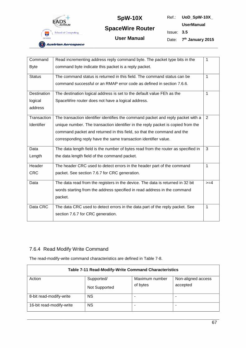
SpW-10X
SpaceWire Router
User Manual
Ref.: UoD_SpW-10X_
UserManual
Issue: 3.5
Date: 7th January 2015
67
Command
Byte
Read incrementing address reply command byte. The packet type bits in the
command byte indicate this packet is a reply packet.
1
Status The command status is returned in this field. The command status can be
command successful or an RMAP error code as defined in section 7.6.6.
1
Destination
logical
address
The destination logical address is set to the default value FEh as the
SpaceWire router does not have a logical address.
1
Transaction
Identifier
The transaction identifier identifies the command packet and reply packet with a
unique number. The transaction identifier in the reply packet is copied from the
command packet and returned in this field, so that the command and the
corresponding reply have the same transaction identifier value.
2
Data
Length
The data length field is the number of bytes read from the router as specified in
the data length field of the command packet.
3
Header
CRC
The header CRC used to detect errors in the header part of the command
packet. See section 7.6.7 for CRC generation.
1
Data The data read from the registers in the device. The data is returned in 32 bit
words starting from the address specified in read address in the command
packet.
>=4
Data CRC The data CRC used to detect errors in the data part of the reply packet. See
section 7.6.7 for CRC generation.
1
7.6.4 Read Modify Write Command
The read-modify-write command characteristics are defined in Table 7-8.
Table 7-11 Read-Modify-Write Command Characteristics
Action Supported/
Not Supported
Maximum number
of bytes
Non-aligned access
accepted
8-bit read-modify-write NS - -
16-bit read-modify-write NS - -
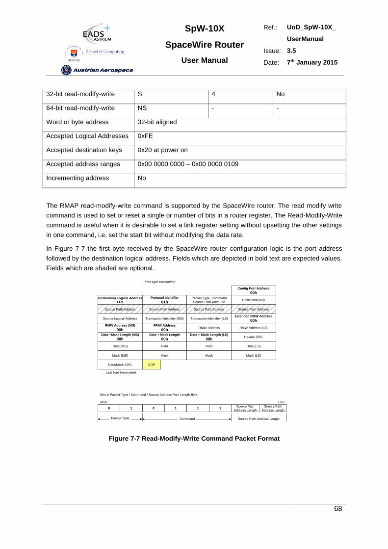
SpW-10X
SpaceWire Router
User Manual
Ref.: UoD_SpW-10X_
UserManual
Issue: 3.5
Date: 7th January 2015
68
32-bit read-modify-write S 4 No
64-bit read-modify-write NS - -
Word or byte address 32-bit aligned
Accepted Logical Addresses 0xFE
Accepted destination keys 0x20 at power on
Accepted address ranges 0x00 0000 0000 – 0x00 0000 0109
Incrementing address No
The RMAP read-modify-write command is supported by the SpaceWire router. The read modify write
command is used to set or reset a single or number of bits in a router register. The Read-Modify-Write
command is useful when it is desirable to set a link register setting without upsetting the other settings
in one command, i.e. set the start bit without modifying the data rate.
In Figure 7-7 the first byte received by the SpaceWire router configuration logic is the port address
followed by the destination logical address. Fields which are depicted in bold text are expected values.
Fields which are shaded are optional.
Destination Logical Address
FEh
Protocol Identifier
01hPacket Type, Command
Source Path Addr LenDestination Key
Source Path Address Source Path Address Source Path Address Source Path Address
Source Logical Address Transaction Identifier (MS) Transaction Identifier (LS)Extended RMW Address
00h
RMW Address (MS)
00hRMW Address
00hRMW Address RMW Address (LS)
Data +Mask Length (MS)
00hData + Mask Length
00hData + Mask Length (LS)
08hHeader CRC
Data (MS) Data Data Data (LS)
Config Port Address
00h
Data/Mask CRC EOP
First byte transmitted
Last byte transmitted
0 11 110
Bits in Packet Type / Command / Source Address Path Length Byte
MSB
Packet Type Command
Mask (MS) Mask Mask Mask (LS)
Source Path
Address Length
Source Path
Address Length
LSB
Source Path Address Length
Figure 7-7 Read-Modify-Write Command Packet Format
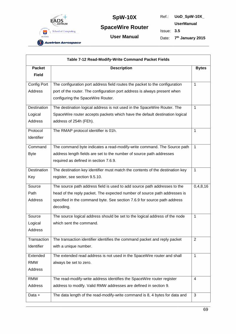
SpW-10X
SpaceWire Router
User Manual
Ref.: UoD_SpW-10X_
UserManual
Issue: 3.5
Date: 7th January 2015
69
Table 7-12 Read-Modify-Write Command Packet Fields
Packet
Field
Description Bytes
Config Port
Address
The configuration port address field routes the packet to the configuration
port of the router. The configuration port address is always present when
configuring the SpaceWire Router.
1
Destination
Logical
Address
The destination logical address is not used in the SpaceWire Router. The
SpaceWire router accepts packets which have the default destination logical
address of 254h (FEh).
1
Protocol
Identifier
The RMAP protocol identifier is 01h. 1
Command
Byte
The command byte indicates a read-modify-write command. The Source path
address length fields are set to the number of source path addresses
required as defined in section 7.6.9.
1
Destination
Key
The destination key identifier must match the contents of the destination key
register, see section 9.5.10.
1
Source
Path
Address
The source path address field is used to add source path addresses to the
head of the reply packet. The expected number of source path addresses is
specified in the command byte. See section 7.6.9 for source path address
decoding.
0,4,8,16
Source
Logical
Address
The source logical address should be set to the logical address of the node
which sent the command.
1
Transaction
Identifier
The transaction identifier identifies the command packet and reply packet
with a unique number.
2
Extended
RMW
Address
The extended read address is not used in the SpaceWire router and shall
always be set to zero.
1
RMW
Address
The read-modify-write address identifies the SpaceWire router register
address to modify. Valid RMW addresses are defined in section 9.
4
Data + The data length of the read-modify-write command is 8, 4 bytes for data and 3
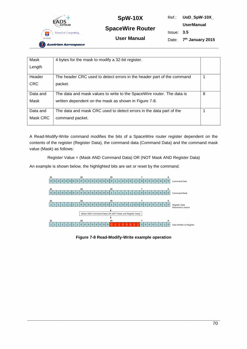
SpW-10X
SpaceWire Router
User Manual
Ref.: UoD_SpW-10X_
UserManual
Issue: 3.5
Date: 7th January 2015
70
Mask
Length
4 bytes for the mask to modify a 32-bit register.
Header
CRC
The header CRC used to detect errors in the header part of the command
packet.
1
Data and
Mask
The data and mask values to write to the SpaceWire router. The data is
written dependent on the mask as shown in Figure 7-8.
8
Data and
Mask CRC
The data and mask CRC used to detect errors in the data part of the
command packet.
1
A Read-Modify-Write command modifies the bits of a SpaceWire router register dependent on the
contents of the register (Register Data), the command data (Command Data) and the command mask
value (Mask) as follows:
Register Value = (Mask AND Command Data) OR (NOT Mask AND Register Data)
An example is shown below, the highlighted bits are set or reset by the command.
0 0 0 0 0 0 0 0 0 0 0 0 0 0 0 0
31 23
0 1 1 0 0 0 1 1 0 0 0 0 0 0 0 0
15 07
Command Data
0 0 0 0 0 0 0 0 0 0 0 0 0 0 0 0
31 23
1 1 1 1 1 1 1 1 0 0 0 0 0 0 0 0
15 07
Command Mask
1 1 1 1 1 1 1 1 0 0 0 0 0 0 0 0
31 23
1 0 1 0 0 1 0 0 0 0 0 0 1 0 1 0
15 07
Register Data
Returned to source
1 1 1 1 1 1 1 1 0 0 0 0 0 0 0 0
31 23
0 1 1 0 0 0 1 1 0 0 0 0 1 0 1 0
15 07
Data Written to Register
(Mask AND Command Data) OR (NOT Mask and Register Data)
Figure 7-8 Read-Modify-Write example operation
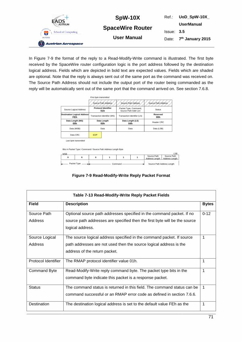
SpW-10X
SpaceWire Router
User Manual
Ref.: UoD_SpW-10X_
UserManual
Issue: 3.5
Date: 7th January 2015
71
In Figure 7-9 the format of the reply to a Read-Modify-Write command is illustrated. The first byte
received by the SpaceWire router configuration logic is the port address followed by the destination
logical address. Fields which are depicted in bold text are expected values. Fields which are shaded
are optional. Note that the reply is always sent out of the same port as the command was received on.
The Source Path Address should not include the output port of the router being commanded as the
reply will be automatically sent out of the same port that the command arrived on. See section 7.6.8.
Source Path Address
Source Logical AddressProtocol Identifier
01hPacket Type, Command,
Source Path Addr LenStatus
Destination Logical Address
FEhTransaction Identifier (MS) Transaction Identifier (LS)
Reserved
00h
Data Length (MS)
00hData Length
00hData Length (LS)
04hHeader CRC
Data (MSB) Data Data Data (LSB)
Source Path Address Source Path Address
Data CRC EOP
First byte transmitted
Last byte transmitted
0 10 110
Bits in Packet Type / Command / Source Path Address Length Byte
MSB
Packet Type Command
Source Path
Address Length
Source Path
Address Length
LSB
Source Path Address Length
Figure 7-9 Read-Modify-Write Reply Packet Format
Table 7-13 Read-Modify-Write Reply Packet Fields
Field Description Bytes
Source Path
Address
Optional source path addresses specified in the command packet. If no
source path addresses are specified then the first byte will be the source
logical address.
0-12
Source Logical
Address
The source logical address specified in the command packet. If source
path addresses are not used then the source logical address is the
address of the return packet.
1
Protocol Identifier The RMAP protocol identifier value 01h. 1
Command Byte Read-Modify-Write reply command byte. The packet type bits in the
command byte indicate this packet is a response packet.
1
Status The command status is returned in this field. The command status can be
command successful or an RMAP error code as defined in section 7.6.6.
1
Destination The destination logical address is set to the default value FEh as the 1
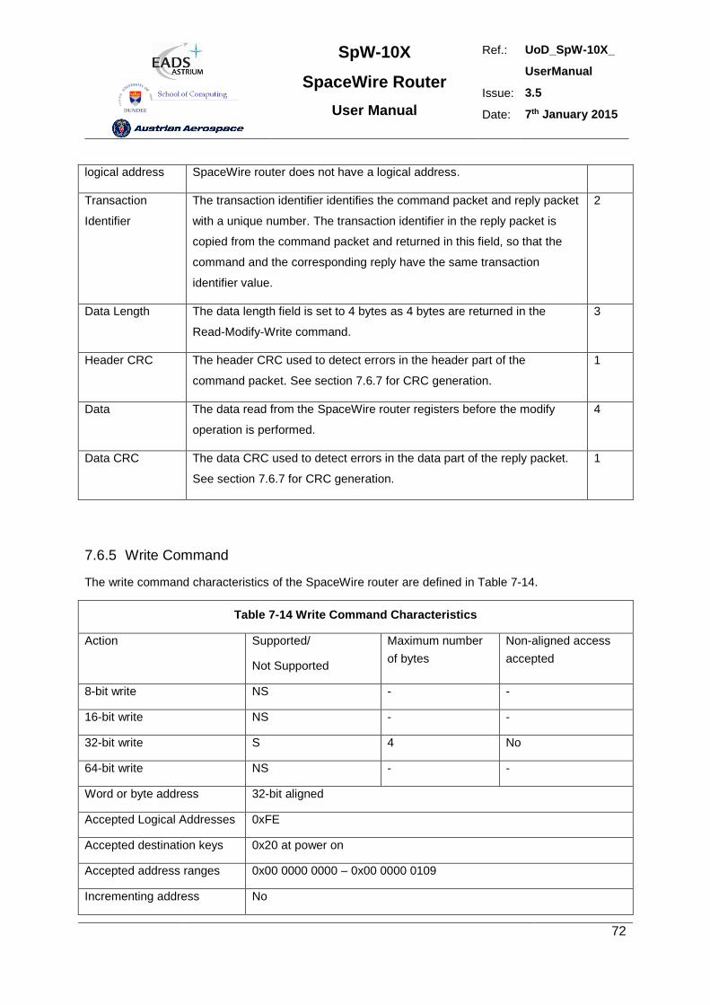
SpW-10X
SpaceWire Router
User Manual
Ref.: UoD_SpW-10X_
UserManual
Issue: 3.5
Date: 7th January 2015
72
logical address SpaceWire router does not have a logical address.
Transaction
Identifier
The transaction identifier identifies the command packet and reply packet
with a unique number. The transaction identifier in the reply packet is
copied from the command packet and returned in this field, so that the
command and the corresponding reply have the same transaction
identifier value.
2
Data Length The data length field is set to 4 bytes as 4 bytes are returned in the
Read-Modify-Write command.
3
Header CRC The header CRC used to detect errors in the header part of the
command packet. See section 7.6.7 for CRC generation.
1
Data The data read from the SpaceWire router registers before the modify
operation is performed.
4
Data CRC The data CRC used to detect errors in the data part of the reply packet.
See section 7.6.7 for CRC generation.
1
7.6.5 Write Command
The write command characteristics of the SpaceWire router are defined in Table 7-14.
Table 7-14 Write Command Characteristics
Action Supported/
Not Supported
Maximum number
of bytes
Non-aligned access
accepted
8-bit write NS - -
16-bit write NS - -
32-bit write S 4 No
64-bit write NS - -
Word or byte address 32-bit aligned
Accepted Logical Addresses 0xFE
Accepted destination keys 0x20 at power on
Accepted address ranges 0x00 0000 0000 – 0x00 0000 0109
Incrementing address No
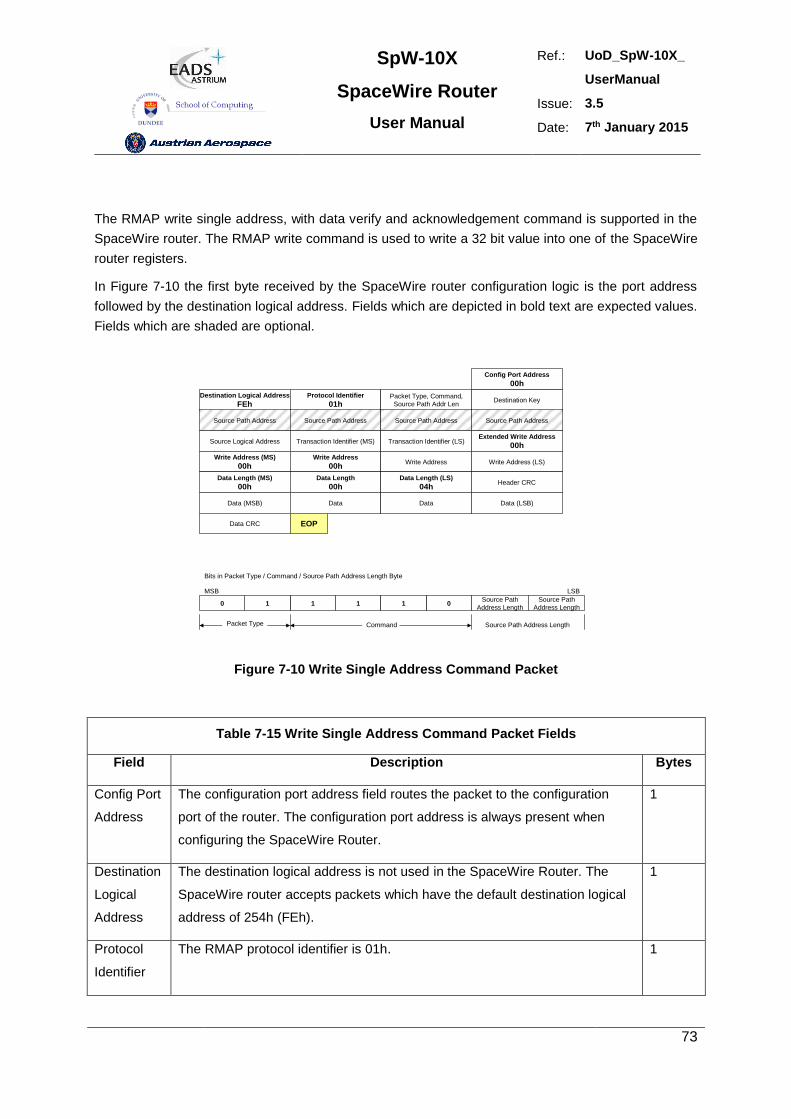
SpW-10X
SpaceWire Router
User Manual
Ref.: UoD_SpW-10X_
UserManual
Issue: 3.5
Date: 7th January 2015
73
The RMAP write single address, with data verify and acknowledgement command is supported in the
SpaceWire router. The RMAP write command is used to write a 32 bit value into one of the SpaceWire
router registers.
In Figure 7-10 the first byte received by the SpaceWire router configuration logic is the port address
followed by the destination logical address. Fields which are depicted in bold text are expected values.
Fields which are shaded are optional.
Destination Logical Address
FEhProtocol Identifier
01hPacket Type, Command,
Source Path Addr LenDestination Key
Source Path Address Source Path Address Source Path Address Source Path Address
Source Logical Address Transaction Identifier (MS) Transaction Identifier (LS)Extended Write Address
00h
Write Address (MS)
00hWrite Address
00hWrite Address Write Address (LS)
Data Length (MS)
00hData Length
00hData Length (LS)
04hHeader CRC
Data (MSB) Data Data Data (LSB)
Config Port Address
00h
Data CRC EOP
1 11 010Source Path
Address Length
Source Path
Address Length
Bits in Packet Type / Command / Source Path Address Length Byte
MSB LSB
Packet Type Command Source Path Address Length
Figure 7-10 Write Single Address Command Packet
Table 7-15 Write Single Address Command Packet Fields
Field Description Bytes
Config Port
Address
The configuration port address field routes the packet to the configuration
port of the router. The configuration port address is always present when
configuring the SpaceWire Router.
1
Destination
Logical
Address
The destination logical address is not used in the SpaceWire Router. The
SpaceWire router accepts packets which have the default destination logical
address of 254h (FEh).
1
Protocol
Identifier
The RMAP protocol identifier is 01h. 1
SpW-10X
SpaceWire Router
User Manual
Ref.: UoD_SpW-10X_
UserManual
Issue: 3.5
Date: 7th January 2015
74
Command
Byte
The command byte indicates a write single address, with verification and
acknowledgement packet. The Source path address length fields are set to
the number of source path addresses required as defined in section 7.6.9.
1
Destination
Key
The destination key identifier must match the contents of the destination key
register, see section 9.5.10.
1
Source
Path
Address
The source path address field is used to add source path addresses to the
head of the reply packet. The expected number of source path addresses is
specified in the command byte. See section 7.6.9 for source path address
decoding.
0,4,8,12
Source
Logical
Address
The source logical address should be set to the logical address of the node
which sent the command.
1
Transaction
Identifier
The transaction identifier identifies the command packet and reply packet
with a unique number.
2
Extended
Write
Address
The extended write address is not used in the SpaceWire router and is
always expected to be zero.
1
Write
Address
The write address identifies the register to write the RMAP data. The valid
write addresses are defined in section 9.
4
Data
Length
The data length of a write single address command is expected to be 4 bytes,
to write to a 32 bit register location
3
Header
CRC
The header CRC is the eight bit CRC code used to detect errors in the
command packet. The CRC code is checked before the command is
executed
1
Data The 32 bit data value to write to the SpaceWire router register. 4
Data CRC The data CRC used to detect errors in the data part of the command packet. 1
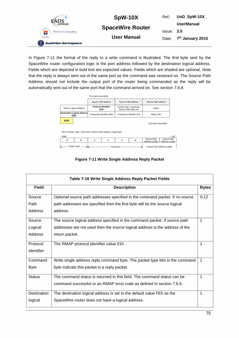
SpW-10X
SpaceWire Router
User Manual
Ref.: UoD_SpW-10X_
UserManual
Issue: 3.5
Date: 7th January 2015
75
In Figure 7-11 the format of the reply to a write command is illustrated. The first byte sent by the
SpaceWire router configuration logic is the port address followed by the destination logical address.
Fields which are depicted in bold text are expected values. Fields which are shaded are optional. Note
that the reply is always sent out of the same port as the command was received on. The Source Path
Address should not include the output port of the router being commanded as the reply will be
automatically sent out of the same port that the command arrived on. See section 7.6.8.
Source Path Address
Source Logical AddressProtocol Identifier
01hPacket Type, Command,
Source Path Addr LenStatus
Destination Logical Address
FEhTransaction Identifier (MS) Transaction Identifier (LS) Reply CRC
Source Path Address Source Path Address
EOP
First byte transmitted
Last byte transmitted
1 10 010
Bits in Packet Type / Command / Source Path Address Length Byte
MSB
Packet Type Command
Source Path
Address Length
Source Path
Address Length
LSB
Source Path Address Length
Figure 7-11 Write Single Address Reply Packet
Table 7-16 Write Single Address Reply Packet Fields
Field Description Bytes
Source
Path
Address
Optional source path addresses specified in the command packet. If no source
path addresses are specified then the first byte will be the source logical
address.
0-12
Source
Logical
Address
The source logical address specified in the command packet. If source path
addresses are not used then the source logical address is the address of the
return packet.
1
Protocol
Identifier
The RMAP protocol identifier value 01h. 1
Command
Byte
Write single address reply command byte. The packet type bits in the command
byte indicate this packet is a reply packet.
1
Status The command status is returned in this field. The command status can be
command successful or an RMAP error code as defined in section 7.6.6.
1
Destination
logical
The destination logical address is set to the default value FEh as the
SpaceWire router does not have a logical address.
1
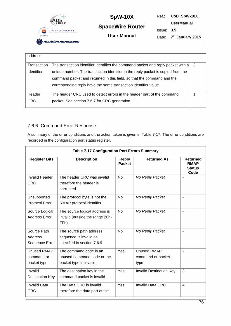
SpW-10X
SpaceWire Router
User Manual
Ref.: UoD_SpW-10X_
UserManual
Issue: 3.5
Date: 7th January 2015
76
address
Transaction
Identifier
The transaction identifier identifies the command packet and reply packet with a
unique number. The transaction identifier in the reply packet is copied from the
command packet and returned in this field, so that the command and the
corresponding reply have the same transaction identifier value.
2
Header
CRC
The header CRC used to detect errors in the header part of the command
packet. See section 7.6.7 for CRC generation.
1
7.6.6 Command Error Response
A summary of the error conditions and the action taken is given in Table 7-17. The error conditions are
recorded in the configuration port status register.
Table 7-17 Configuration Port Errors Summary
Register Bits Description Reply Packet
Returned As Returned RMAP Status Code
Invalid Header
CRC
The header CRC was invalid
therefore the header is
corrupted
No No Reply Packet. -
Unsupported
Protocol Error
The protocol byte is not the
RMAP protocol identifier
No No Reply Packet. -
Source Logical
Address Error
The source logical address is
invalid (outside the range 20h-
FFh)
No No Reply Packet. -
Source Path
Address
Sequence Error
The source path address
sequence is invalid as
specified in section 7.6.9
No No Reply Packet. -
Unused RMAP
command or
packet type
The command code is an
unused command code or the
packet type is invalid.
Yes Unused RMAP
command or packet
type
2
Invalid
Destination Key
The destination key in the
command packet is invalid.
Yes Invalid Destination Key 3
Invalid Data
CRC
The Data CRC is invalid
therefore the data part of the
Yes Invalid Data CRC 4
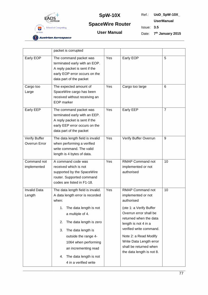
SpW-10X
SpaceWire Router
User Manual
Ref.: UoD_SpW-10X_
UserManual
Issue: 3.5
Date: 7th January 2015
77
packet is corrupted
Early EOP The command packet was
terminated early with an EOP.
A reply packet is sent if the
early EOP error occurs on the
data part of the packet
Yes Early EOP 5
Cargo too
Large
The expected amount of
SpaceWire cargo has been
received without receiving an
EOP marker
Yes Cargo too large 6
Early EEP The command packet was
terminated early with an EEP.
A reply packet is sent if the
early EEP error occurs on the
data part of the packet
Yes Early EEP 7
Verify Buffer
Overrun Error
The data length field is invalid
when performing a verified
write command. The valid
length is 4 bytes of data.
Yes Verify Buffer Overrun 9
Command not
implemented
A command code was
received which is not
supported by the SpaceWire
router. Supported command
codes are listed in F1-18.
Yes RMAP Command not
implemented or not
authorised
10
Invalid Data
Length
The data length field is invalid.
A data length error is recorded
when:
1. The data length is not
a multiple of 4.
2. The data length is zero
3. The data length is
outside the range 4-
1064 when performing
an incrementing read
4. The data length is not
4 in a verified write
Yes RMAP Command not
implemented or not
authorised
(ote 1: a Verify Buffer
Overrun error shall be
returned when the data
length is not 4 in a
verified write command.
Note 2: a Read Modify
Write Data Length error
shall be returned when
the data length is not 8.
10
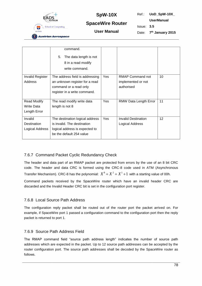
SpW-10X
SpaceWire Router
User Manual
Ref.: UoD_SpW-10X_
UserManual
Issue: 3.5
Date: 7th January 2015
78
command.
5. The data length is not
8 in a read modify
write command.
Invalid Register
Address
The address field is addressing
an unknown register for a read
command or a read only
register in a write command.
Yes RMAP Command not
implemented or not
authorised
10
Read Modify
Write Data
Length Error
The read modify write data
length is not 8
Yes RMW Data Length Error 11
Invalid
Destination
Logical Address
The destination logical address
is invalid. The destination
logical address is expected to
be the default 254 value
Yes Invalid Destination
Logical Address
12
7.6.7 Command Packet Cyclic Redundancy Check
The header and data part of an RMAP packet are protected from errors by the use of an 8 bit CRC
code. The header and data CRC is formed using the CRC-8 code used in ATM (Asynchronous
Transfer Mechanism). CRC-8 has the polynomial: 1128 XXX with a starting value of 00h.
Command packets received by the SpaceWire router which have an invalid header CRC are
discarded and the Invalid Header CRC bit is set in the configuration port register.
7.6.8 Local Source Path Address
The configuration reply packet shall be routed out of the router port the packet arrived on. For
example, if SpaceWire port 1 passed a configuration command to the configuration port then the reply
packet is returned to port 1.
7.6.9 Source Path Address Field
The RMAP command field “source path address length” indicates the number of source path
addresses which are expected in the packet. Up to 12 source path addresses can be accepted by the
router configuration port. The source path addresses shall be decoded by the SpaceWire router as
follows.
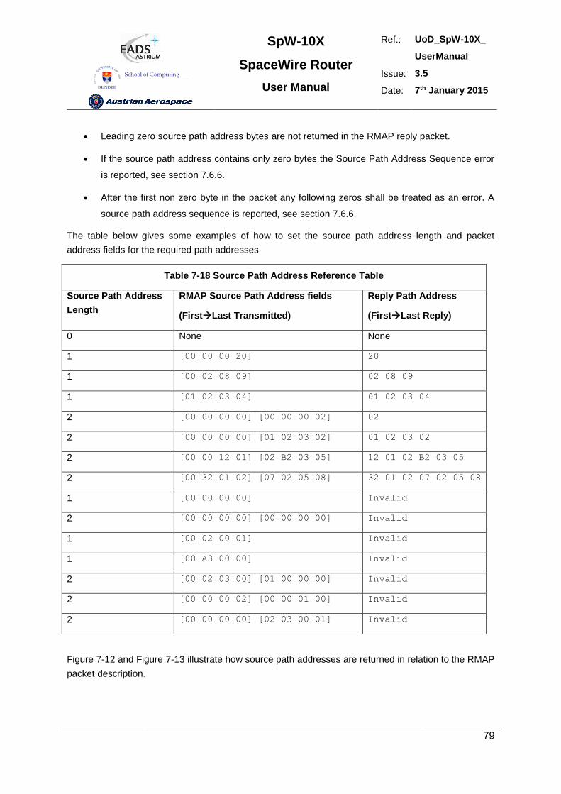
SpW-10X
SpaceWire Router
User Manual
Ref.: UoD_SpW-10X_
UserManual
Issue: 3.5
Date: 7th January 2015
79
Leading zero source path address bytes are not returned in the RMAP reply packet.
If the source path address contains only zero bytes the Source Path Address Sequence error
is reported, see section 7.6.6.
After the first non zero byte in the packet any following zeros shall be treated as an error. A
source path address sequence is reported, see section 7.6.6.
The table below gives some examples of how to set the source path address length and packet
address fields for the required path addresses
Table 7-18 Source Path Address Reference Table
Source Path Address
Length
RMAP Source Path Address fields
(FirstLast Transmitted)
Reply Path Address
(FirstLast Reply)
0 None None
1 [00 00 00 20] 20
1 [00 02 08 09] 02 08 09
1 [01 02 03 04] 01 02 03 04
2 [00 00 00 00] [00 00 00 02] 02
2 [00 00 00 00] [01 02 03 02] 01 02 03 02
2 [00 00 12 01] [02 B2 03 05] 12 01 02 B2 03 05
2 [00 32 01 02] [07 02 05 08] 32 01 02 07 02 05 08
1 [00 00 00 00] Invalid
2 [00 00 00 00] [00 00 00 00] Invalid
1 [00 02 00 01] Invalid
1 [00 A3 00 00] Invalid
2 [00 02 03 00] [01 00 00 00] Invalid
2 [00 00 00 02] [00 00 01 00] Invalid
2 [00 00 00 00] [02 03 00 01] Invalid
Figure 7-12 and Figure 7-13 illustrate how source path addresses are returned in relation to the RMAP
packet description.
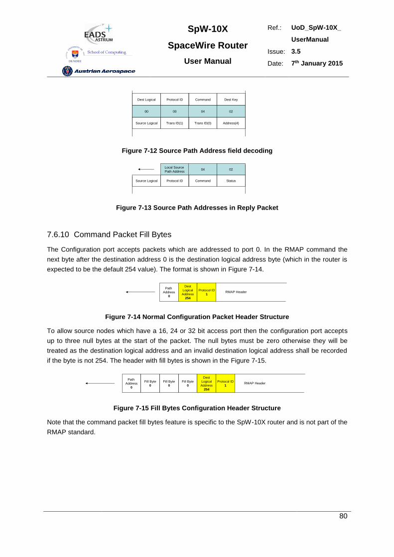
SpW-10X
SpaceWire Router
User Manual
Ref.: UoD_SpW-10X_
UserManual
Issue: 3.5
Date: 7th January 2015
80
00 00 04 02
Dest Logical Protocol ID Command Dest Key
Source Logical Trans ID(1) Trans ID(0) Address(4)
Figure 7-12 Source Path Address field decoding
Source Logical Protocol ID Command Status
0204Local Source
Path Address
Figure 7-13 Source Path Addresses in Reply Packet
7.6.10 Command Packet Fill Bytes
The Configuration port accepts packets which are addressed to port 0. In the RMAP command the
next byte after the destination address 0 is the destination logical address byte (which in the router is
expected to be the default 254 value). The format is shown in Figure 7-14.
Path
Address
0
Dest
Logical
Address
254
Protocol ID
1RMAP Header
Figure 7-14 Normal Configuration Packet Header Structure
To allow source nodes which have a 16, 24 or 32 bit access port then the configuration port accepts
up to three null bytes at the start of the packet. The null bytes must be zero otherwise they will be
treated as the destination logical address and an invalid destination logical address shall be recorded
if the byte is not 254. The header with fill bytes is shown in the Figure 7-15.
Fill Byte
0
Dest
Logical
Address
254
Protocol ID
1RMAP Header
Fill Byte
0
Fill Byte
0
Path
Address
0
Figure 7-15 Fill Bytes Configuration Header Structure
Note that the command packet fill bytes feature is specific to the SpW-10X router and is not part of the
RMAP standard.
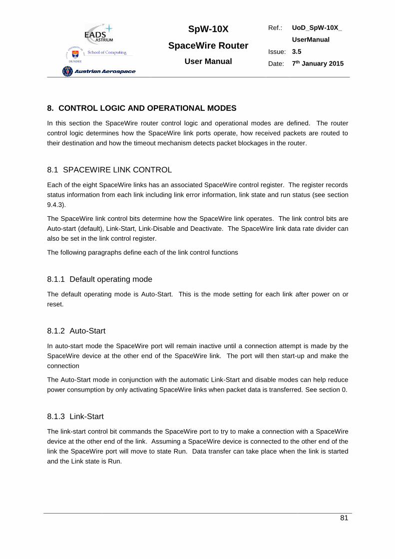
SpW-10X
SpaceWire Router
User Manual
Ref.: UoD_SpW-10X_
UserManual
Issue: 3.5
Date: 7th January 2015
81
8. CONTROL LOGIC AND OPERATIONAL MODES
In this section the SpaceWire router control logic and operational modes are defined. The router
control logic determines how the SpaceWire link ports operate, how received packets are routed to
their destination and how the timeout mechanism detects packet blockages in the router.
8.1 SPACEWIRE LINK CONTROL
Each of the eight SpaceWire links has an associated SpaceWire control register. The register records
status information from each link including link error information, link state and run status (see section
9.4.3).
The SpaceWire link control bits determine how the SpaceWire link operates. The link control bits are
Auto-start (default), Link-Start, Link-Disable and Deactivate. The SpaceWire link data rate divider can
also be set in the link control register.
The following paragraphs define each of the link control functions
8.1.1 Default operating mode
The default operating mode is Auto-Start. This is the mode setting for each link after power on or
reset.
8.1.2 Auto-Start
In auto-start mode the SpaceWire port will remain inactive until a connection attempt is made by the
SpaceWire device at the other end of the SpaceWire link. The port will then start-up and make the
connection
The Auto-Start mode in conjunction with the automatic Link-Start and disable modes can help reduce
power consumption by only activating SpaceWire links when packet data is transferred. See section 0.
8.1.3 Link-Start
The link-start control bit commands the SpaceWire port to try to make a connection with a SpaceWire
device at the other end of the link. Assuming a SpaceWire device is connected to the other end of the
link the SpaceWire port will move to state Run. Data transfer can take place when the link is started
and the Link state is Run.
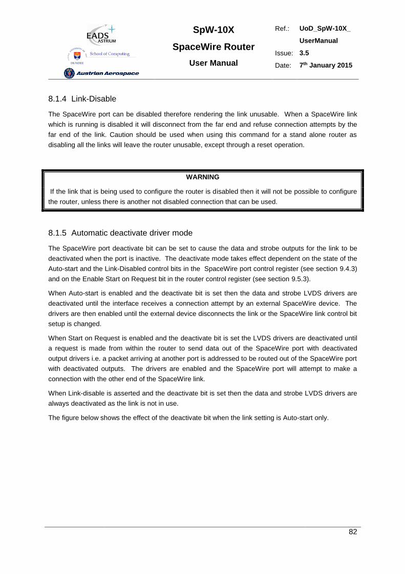
SpW-10X
SpaceWire Router
User Manual
Ref.: UoD_SpW-10X_
UserManual
Issue: 3.5
Date: 7th January 2015
82
8.1.4 Link-Disable
The SpaceWire port can be disabled therefore rendering the link unusable. When a SpaceWire link
which is running is disabled it will disconnect from the far end and refuse connection attempts by the
far end of the link. Caution should be used when using this command for a stand alone router as
disabling all the links will leave the router unusable, except through a reset operation.
WARNING
If the link that is being used to configure the router is disabled then it will not be possible to configure
the router, unless there is another not disabled connection that can be used.
8.1.5 Automatic deactivate driver mode
The SpaceWire port deactivate bit can be set to cause the data and strobe outputs for the link to be
deactivated when the port is inactive. The deactivate mode takes effect dependent on the state of the
Auto-start and the Link-Disabled control bits in the SpaceWire port control register (see section 9.4.3)
and on the Enable Start on Request bit in the router control register (see section 9.5.3).
When Auto-start is enabled and the deactivate bit is set then the data and strobe LVDS drivers are
deactivated until the interface receives a connection attempt by an external SpaceWire device. The
drivers are then enabled until the external device disconnects the link or the SpaceWire link control bit
setup is changed.
When Start on Request is enabled and the deactivate bit is set the LVDS drivers are deactivated until
a request is made from within the router to send data out of the SpaceWire port with deactivated
output drivers i.e. a packet arriving at another port is addressed to be routed out of the SpaceWire port
with deactivated outputs. The drivers are enabled and the SpaceWire port will attempt to make a
connection with the other end of the SpaceWire link.
When Link-disable is asserted and the deactivate bit is set then the data and strobe LVDS drivers are
always deactivated as the link is not in use.
The figure below shows the effect of the deactivate bit when the link setting is Auto-start only.
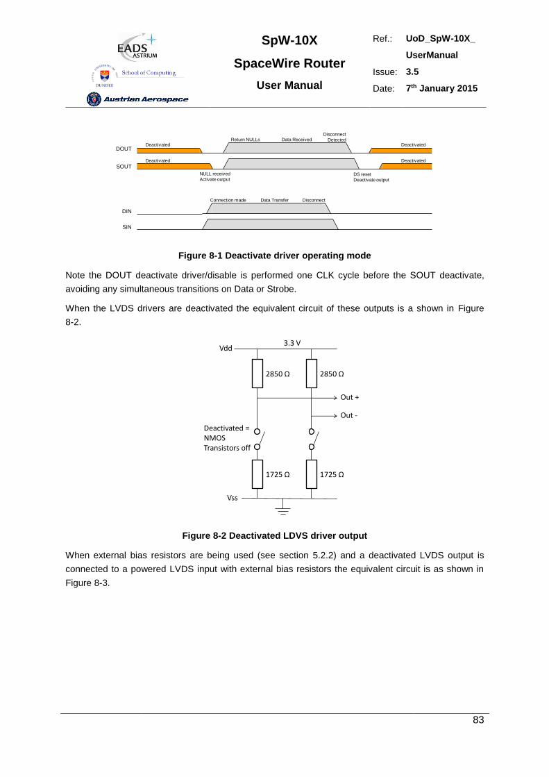
SpW-10X
SpaceWire Router
User Manual
Ref.: UoD_SpW-10X_
UserManual
Issue: 3.5
Date: 7th January 2015
83
DOUT
SOUT
DIN
SIN
Connection made Data Transfer Disconnect
Deactivated
DeactivatedReturn NULLs
Disconnect
DetectedData Received
NULL received
Activate outputDS reset
Deactivate output
Deactivated
Deactivated
Figure 8-1 Deactivate driver operating mode
Note the DOUT deactivate driver/disable is performed one CLK cycle before the SOUT deactivate,
avoiding any simultaneous transitions on Data or Strobe.
When the LVDS drivers are deactivated the equivalent circuit of these outputs is a shown in Figure
8-2.
3.3 V
Out +
Out -
2850 Ω 2850 Ω
1725 Ω 1725 Ω
Vdd
Vss
Deactivated =NMOSTransistors off
Figure 8-2 Deactivated LDVS driver output
When external bias resistors are being used (see section 5.2.2) and a deactivated LVDS output is
connected to a powered LVDS input with external bias resistors the equivalent circuit is as shown in
Figure 8-3.
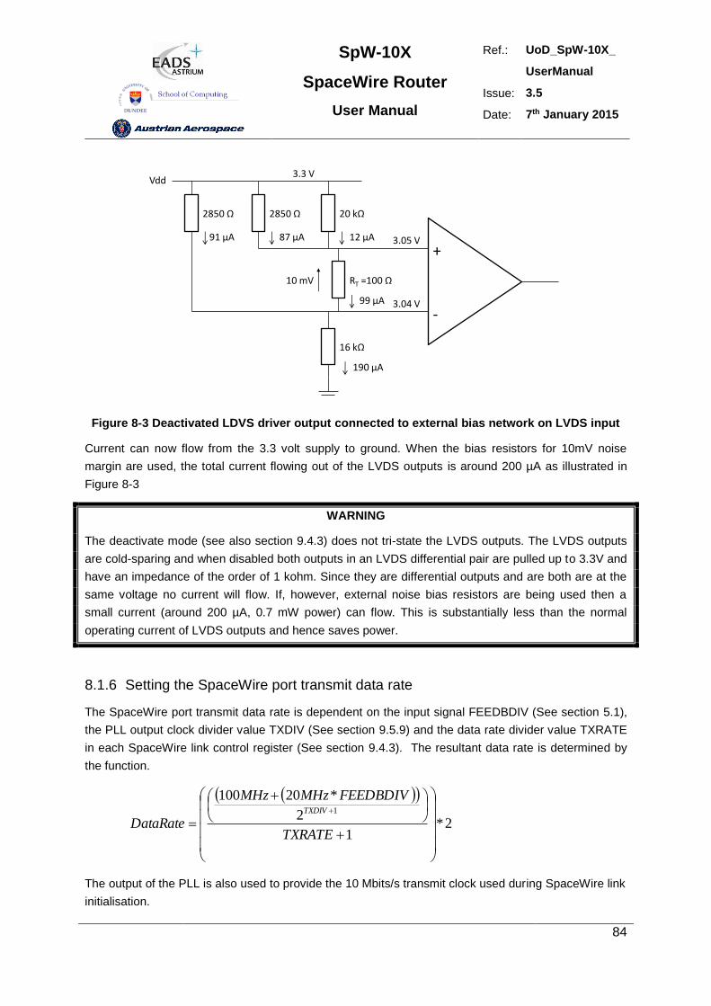
SpW-10X
SpaceWire Router
User Manual
Ref.: UoD_SpW-10X_
UserManual
Issue: 3.5
Date: 7th January 2015
84
3.3 V
2850 Ω 20 kΩ
RT =100 Ω
16 kΩ
Vdd
2850 Ω
91 µA 87 µA 12 µA
99 µA
190 µA
3.05 V
3.04 V
10 mV
-
+
Figure 8-3 Deactivated LDVS driver output connected to external bias network on LVDS input
Current can now flow from the 3.3 volt supply to ground. When the bias resistors for 10mV noise
margin are used, the total current flowing out of the LVDS outputs is around 200 µA as illustrated in
Figure 8-3
WARNING
The deactivate mode (see also section 9.4.3) does not tri-state the LVDS outputs. The LVDS outputs
are cold-sparing and when disabled both outputs in an LVDS differential pair are pulled up to 3.3V and
have an impedance of the order of 1 kohm. Since they are differential outputs and are both are at the
same voltage no current will flow. If, however, external noise bias resistors are being used then a
small current (around 200 µA, 0.7 mW power) can flow. This is substantially less than the normal
operating current of LVDS outputs and hence saves power.
8.1.6 Setting the SpaceWire port transmit data rate
The SpaceWire port transmit data rate is dependent on the input signal FEEDBDIV (See section 5.1),
the PLL output clock divider value TXDIV (See section 9.5.9) and the data rate divider value TXRATE
in each SpaceWire link control register (See section 9.4.3). The resultant data rate is determined by
the function.
2*1
2
*201001
TXRATE
FEEDBDIVMHzMHz
DataRateTXDIV
The output of the PLL is also used to provide the 10 Mbits/s transmit clock used during SpaceWire link
initialisation.
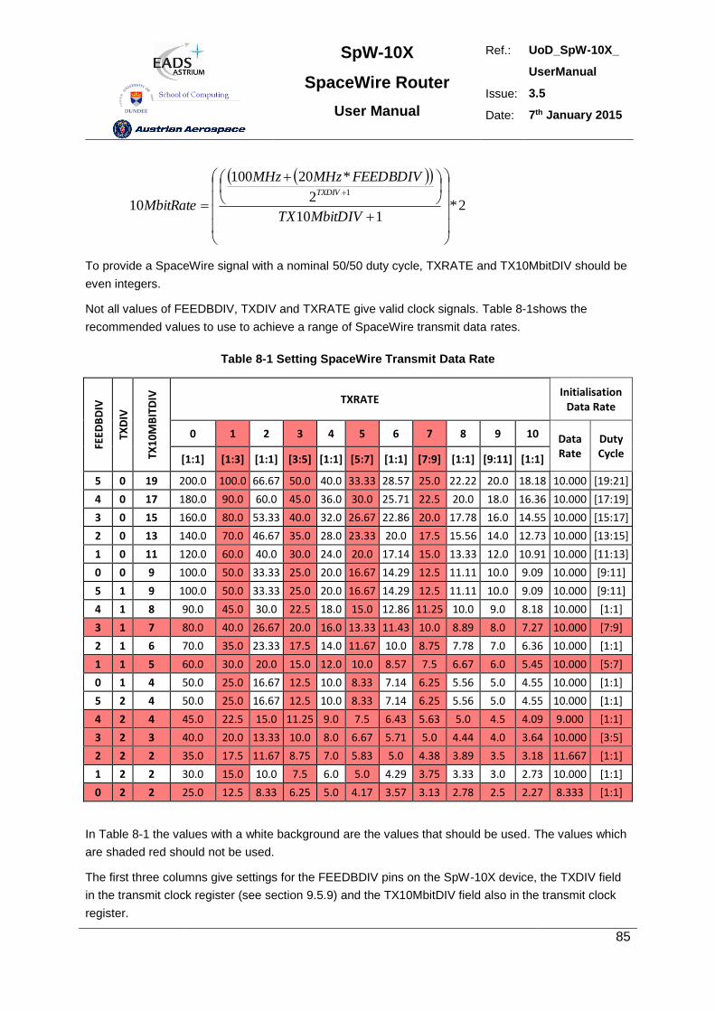
SpW-10X
SpaceWire Router
User Manual
Ref.: UoD_SpW-10X_
UserManual
Issue: 3.5
Date: 7th January 2015
85
2*110
2
*20100
101
MbitDIVTX
FEEDBDIVMHzMHz
MbitRateTXDIV
To provide a SpaceWire signal with a nominal 50/50 duty cycle, TXRATE and TX10MbitDIV should be
even integers.
Not all values of FEEDBDIV, TXDIV and TXRATE give valid clock signals. Table 8-1shows the
recommended values to use to achieve a range of SpaceWire transmit data rates.
Table 8-1 Setting SpaceWire Transmit Data Rate
FEED
BD
IV
TXD
IV
TX1
0M
BIT
DIV
TXRATE Initialisation
Data Rate
0 1 2 3 4 5 6 7 8 9 10 Data Rate
Duty Cycle [1:1] [1:3] [1:1] [3:5] [1:1] [5:7] [1:1] [7:9] [1:1] [9:11] [1:1]
5 0 19 200.0 100.0 66.67 50.0 40.0 33.33 28.57 25.0 22.22 20.0 18.18 10.000 [19:21]
4 0 17 180.0 90.0 60.0 45.0 36.0 30.0 25.71 22.5 20.0 18.0 16.36 10.000 [17:19]
3 0 15 160.0 80.0 53.33 40.0 32.0 26.67 22.86 20.0 17.78 16.0 14.55 10.000 [15:17]
2 0 13 140.0 70.0 46.67 35.0 28.0 23.33 20.0 17.5 15.56 14.0 12.73 10.000 [13:15]
1 0 11 120.0 60.0 40.0 30.0 24.0 20.0 17.14 15.0 13.33 12.0 10.91 10.000 [11:13]
0 0 9 100.0 50.0 33.33 25.0 20.0 16.67 14.29 12.5 11.11 10.0 9.09 10.000 [9:11]
5 1 9 100.0 50.0 33.33 25.0 20.0 16.67 14.29 12.5 11.11 10.0 9.09 10.000 [9:11]
4 1 8 90.0 45.0 30.0 22.5 18.0 15.0 12.86 11.25 10.0 9.0 8.18 10.000 [1:1]
3 1 7 80.0 40.0 26.67 20.0 16.0 13.33 11.43 10.0 8.89 8.0 7.27 10.000 [7:9]
2 1 6 70.0 35.0 23.33 17.5 14.0 11.67 10.0 8.75 7.78 7.0 6.36 10.000 [1:1]
1 1 5 60.0 30.0 20.0 15.0 12.0 10.0 8.57 7.5 6.67 6.0 5.45 10.000 [5:7]
0 1 4 50.0 25.0 16.67 12.5 10.0 8.33 7.14 6.25 5.56 5.0 4.55 10.000 [1:1]
5 2 4 50.0 25.0 16.67 12.5 10.0 8.33 7.14 6.25 5.56 5.0 4.55 10.000 [1:1]
4 2 4 45.0 22.5 15.0 11.25 9.0 7.5 6.43 5.63 5.0 4.5 4.09 9.000 [1:1]
3 2 3 40.0 20.0 13.33 10.0 8.0 6.67 5.71 5.0 4.44 4.0 3.64 10.000 [3:5]
2 2 2 35.0 17.5 11.67 8.75 7.0 5.83 5.0 4.38 3.89 3.5 3.18 11.667 [1:1]
1 2 2 30.0 15.0 10.0 7.5 6.0 5.0 4.29 3.75 3.33 3.0 2.73 10.000 [1:1]
0 2 2 25.0 12.5 8.33 6.25 5.0 4.17 3.57 3.13 2.78 2.5 2.27 8.333 [1:1]
In Table 8-1 the values with a white background are the values that should be used. The values which
are shaded red should not be used.
The first three columns give settings for the FEEDBDIV pins on the SpW-10X device, the TXDIV field
in the transmit clock register (see section 9.5.9) and the TX10MbitDIV field also in the transmit clock
register.
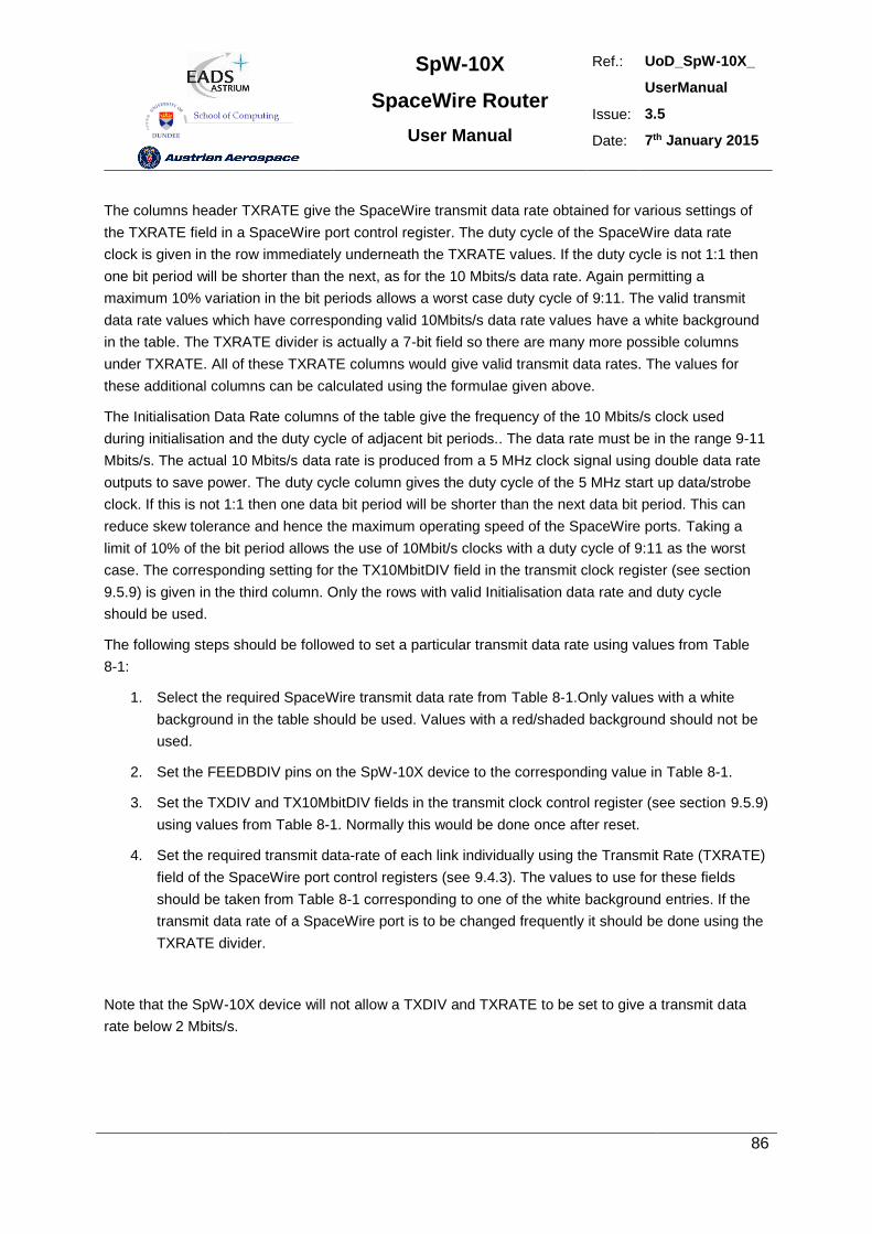
SpW-10X
SpaceWire Router
User Manual
Ref.: UoD_SpW-10X_
UserManual
Issue: 3.5
Date: 7th January 2015
86
The columns header TXRATE give the SpaceWire transmit data rate obtained for various settings of
the TXRATE field in a SpaceWire port control register. The duty cycle of the SpaceWire data rate
clock is given in the row immediately underneath the TXRATE values. If the duty cycle is not 1:1 then
one bit period will be shorter than the next, as for the 10 Mbits/s data rate. Again permitting a
maximum 10% variation in the bit periods allows a worst case duty cycle of 9:11. The valid transmit
data rate values which have corresponding valid 10Mbits/s data rate values have a white background
in the table. The TXRATE divider is actually a 7-bit field so there are many more possible columns
under TXRATE. All of these TXRATE columns would give valid transmit data rates. The values for
these additional columns can be calculated using the formulae given above.
The Initialisation Data Rate columns of the table give the frequency of the 10 Mbits/s clock used
during initialisation and the duty cycle of adjacent bit periods.. The data rate must be in the range 9-11
Mbits/s. The actual 10 Mbits/s data rate is produced from a 5 MHz clock signal using double data rate
outputs to save power. The duty cycle column gives the duty cycle of the 5 MHz start up data/strobe
clock. If this is not 1:1 then one data bit period will be shorter than the next data bit period. This can
reduce skew tolerance and hence the maximum operating speed of the SpaceWire ports. Taking a
limit of 10% of the bit period allows the use of 10Mbit/s clocks with a duty cycle of 9:11 as the worst
case. The corresponding setting for the TX10MbitDIV field in the transmit clock register (see section
9.5.9) is given in the third column. Only the rows with valid Initialisation data rate and duty cycle
should be used.
The following steps should be followed to set a particular transmit data rate using values from Table
8-1:
1. Select the required SpaceWire transmit data rate from Table 8-1.Only values with a white
background in the table should be used. Values with a red/shaded background should not be
used.
2. Set the FEEDBDIV pins on the SpW-10X device to the corresponding value in Table 8-1.
3. Set the TXDIV and TX10MbitDIV fields in the transmit clock control register (see section 9.5.9)
using values from Table 8-1. Normally this would be done once after reset.
4. Set the required transmit data-rate of each link individually using the Transmit Rate (TXRATE)
field of the SpaceWire port control registers (see 9.4.3). The values to use for these fields
should be taken from Table 8-1 corresponding to one of the white background entries. If the
transmit data rate of a SpaceWire port is to be changed frequently it should be done using the
TXRATE divider.
Note that the SpW-10X device will not allow a TXDIV and TXRATE to be set to give a transmit data
rate below 2 Mbits/s.
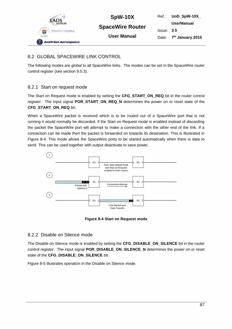
SpW-10X
SpaceWire Router
User Manual
Ref.: UoD_SpW-10X_
UserManual
Issue: 3.5
Date: 7th January 2015
87
8.2 GLOBAL SPACEWIRE LINK CONTROL
The following modes are global to all SpaceWire links. The modes can be set in the SpaceWire router
control register (see section 9.5.3).
8.2.1 Start on request mode
The Start on Request mode is enabled by setting the CFG_START_ON_REQ bit in the router control
register. The input signal POR_START_ON_REQ_N determines the power on or reset state of the
CFG_START_ON_REQ bit.
When a SpaceWire packet is received which is to be routed out of a SpaceWire port that is not
running it would normally be discarded. If the Start on Request mode is enabled instead of discarding
the packet the SpaceWire port will attempt to make a connection with the other end of the link. If a
connection can be made then the packet is forwarded on towards its destination. This is illustrated in
Figure 8-4. This mode allows the SpaceWire ports to be started automatically when there is data to
send. This can be used together with output deactivate to save power.
R1 R21 2 1 2Auto-Start default mode
and Start on Request
enabled in both routers
R1 R21 2 1 22
Packet with
address 2
R1 R21 2 1 2
Connection Attempt
2
Link Started and
Data Transfer
1
2
3
2
Figure 8-4 Start on Request mode
8.2.2 Disable on Silence mode
The Disable on Silence mode is enabled by setting the CFG_DISABLE_ON_SILENCE bit in the router
control register. The input signal POR_DISABLE_ON_SILENCE_N determines the power on or reset
state of the CFG_DISABLE_ON_SILENCE bit.
Figure 8-5 illustrates operation in the Disable on Silence mode.
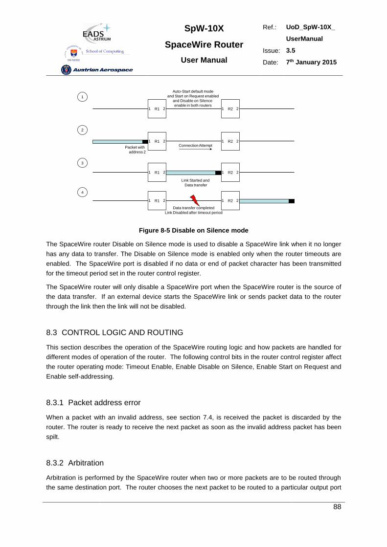
SpW-10X
SpaceWire Router
User Manual
Ref.: UoD_SpW-10X_
UserManual
Issue: 3.5
Date: 7th January 2015
88
R1 R21 2 1 2
Auto-Start default mode
and Start on Request enabled
and Disable on Silence
enable in both routers
R1 R21 2 1 2
Packet with
address 2
R1 R21 2 1 2
Connection Attempt
Link Started and
Data transfer
R1 R21 2 1 2
Data transfer completed
Link Disabled after timeout period
1
2
3
4
Figure 8-5 Disable on Silence mode
The SpaceWire router Disable on Silence mode is used to disable a SpaceWire link when it no longer
has any data to transfer. The Disable on Silence mode is enabled only when the router timeouts are
enabled. The SpaceWire port is disabled if no data or end of packet character has been transmitted
for the timeout period set in the router control register.
The SpaceWire router will only disable a SpaceWire port when the SpaceWire router is the source of
the data transfer. If an external device starts the SpaceWire link or sends packet data to the router
through the link then the link will not be disabled.
8.3 CONTROL LOGIC AND ROUTING
This section describes the operation of the SpaceWire routing logic and how packets are handled for
different modes of operation of the router. The following control bits in the router control register affect
the router operating mode: Timeout Enable, Enable Disable on Silence, Enable Start on Request and
Enable self-addressing.
8.3.1 Packet address error
When a packet with an invalid address, see section 7.4, is received the packet is discarded by the
router. The router is ready to receive the next packet as soon as the invalid address packet has been
spilt.
8.3.2 Arbitration
Arbitration is performed by the SpaceWire router when two or more packets are to be routed through
the same destination port. The router chooses the next packet to be routed to a particular output port
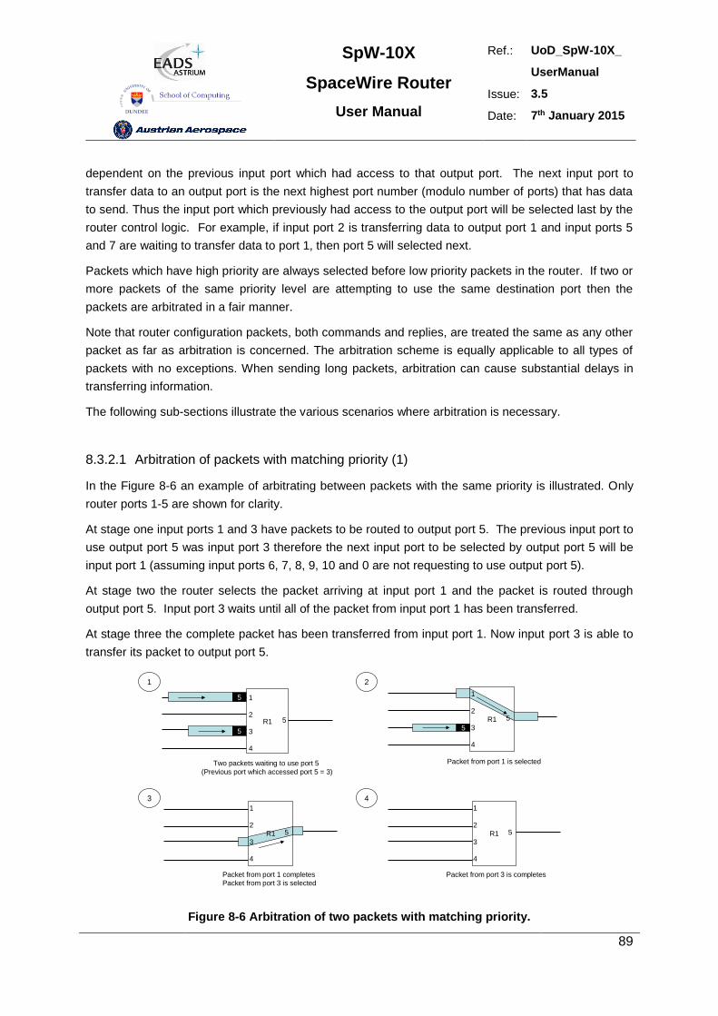
SpW-10X
SpaceWire Router
User Manual
Ref.: UoD_SpW-10X_
UserManual
Issue: 3.5
Date: 7th January 2015
89
dependent on the previous input port which had access to that output port. The next input port to
transfer data to an output port is the next highest port number (modulo number of ports) that has data
to send. Thus the input port which previously had access to the output port will be selected last by the
router control logic. For example, if input port 2 is transferring data to output port 1 and input ports 5
and 7 are waiting to transfer data to port 1, then port 5 will selected next.
Packets which have high priority are always selected before low priority packets in the router. If two or
more packets of the same priority level are attempting to use the same destination port then the
packets are arbitrated in a fair manner.
Note that router configuration packets, both commands and replies, are treated the same as any other
packet as far as arbitration is concerned. The arbitration scheme is equally applicable to all types of
packets with no exceptions. When sending long packets, arbitration can cause substantial delays in
transferring information.
The following sub-sections illustrate the various scenarios where arbitration is necessary.
8.3.2.1 Arbitration of packets with matching priority (1)
In the Figure 8-6 an example of arbitrating between packets with the same priority is illustrated. Only
router ports 1-5 are shown for clarity.
At stage one input ports 1 and 3 have packets to be routed to output port 5. The previous input port to
use output port 5 was input port 3 therefore the next input port to be selected by output port 5 will be
input port 1 (assuming input ports 6, 7, 8, 9, 10 and 0 are not requesting to use output port 5).
At stage two the router selects the packet arriving at input port 1 and the packet is routed through
output port 5. Input port 3 waits until all of the packet from input port 1 has been transferred.
At stage three the complete packet has been transferred from input port 1. Now input port 3 is able to
transfer its packet to output port 5.
R12
5
1
35
4
5
R1
25
1
35
4
Two packets waiting to use port 5
(Previous port which accessed port 5 = 3)
Packet from port 1 is selected
R1
25
1
3
4
Packet from port 1 completes
Packet from port 3 is selected
R1
25
1
3
4
Packet from port 3 is completes
1 2
3 4
Figure 8-6 Arbitration of two packets with matching priority.
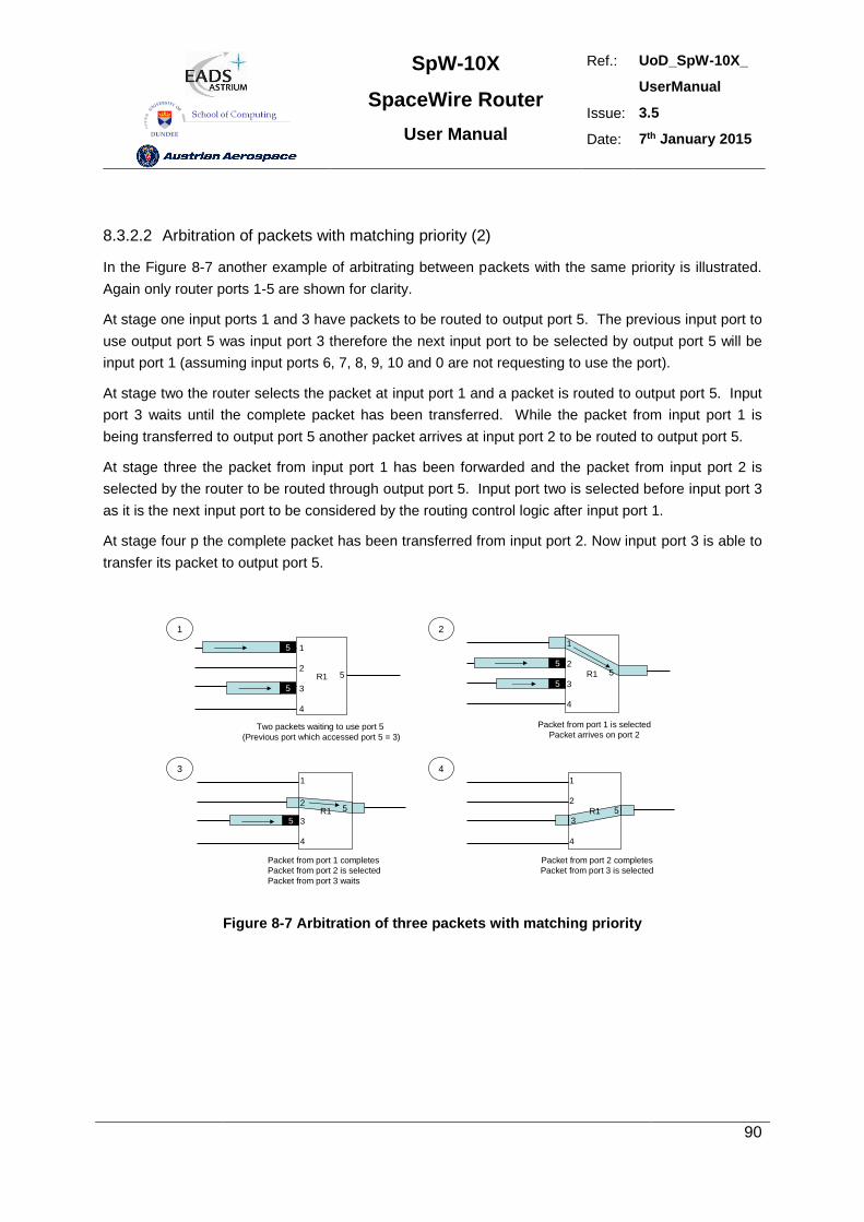
SpW-10X
SpaceWire Router
User Manual
Ref.: UoD_SpW-10X_
UserManual
Issue: 3.5
Date: 7th January 2015
90
8.3.2.2 Arbitration of packets with matching priority (2)
In the Figure 8-7 another example of arbitrating between packets with the same priority is illustrated.
Again only router ports 1-5 are shown for clarity.
At stage one input ports 1 and 3 have packets to be routed to output port 5. The previous input port to
use output port 5 was input port 3 therefore the next input port to be selected by output port 5 will be
input port 1 (assuming input ports 6, 7, 8, 9, 10 and 0 are not requesting to use the port).
At stage two the router selects the packet at input port 1 and a packet is routed to output port 5. Input
port 3 waits until the complete packet has been transferred. While the packet from input port 1 is
being transferred to output port 5 another packet arrives at input port 2 to be routed to output port 5.
At stage three the packet from input port 1 has been forwarded and the packet from input port 2 is
selected by the router to be routed through output port 5. Input port two is selected before input port 3
as it is the next input port to be considered by the routing control logic after input port 1.
At stage four p the complete packet has been transferred from input port 2. Now input port 3 is able to
transfer its packet to output port 5.
R12
5
1
35
4
5
R1
25
1
35
4
Two packets waiting to use port 5
(Previous port which accessed port 5 = 3)
Packet from port 1 is selected
Packet arrives on port 2
R12
5
1
3
4
Packet from port 1 completes
Packet from port 2 is selected
Packet from port 3 waits
R1
25
1
3
4
Packet from port 2 completes
Packet from port 3 is selected
1 2
3 4
5
5
Figure 8-7 Arbitration of three packets with matching priority
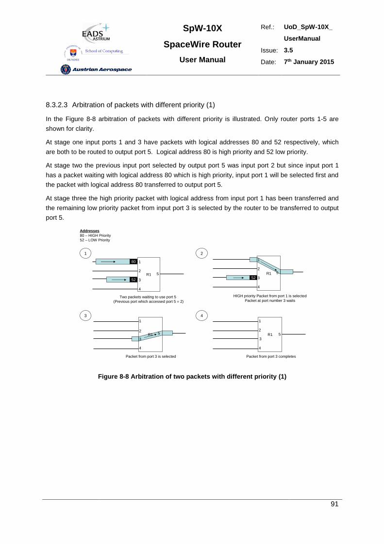
SpW-10X
SpaceWire Router
User Manual
Ref.: UoD_SpW-10X_
UserManual
Issue: 3.5
Date: 7th January 2015
91
8.3.2.3 Arbitration of packets with different priority (1)
In the Figure 8-8 arbitration of packets with different priority is illustrated. Only router ports 1-5 are
shown for clarity.
At stage one input ports 1 and 3 have packets with logical addresses 80 and 52 respectively, which
are both to be routed to output port 5. Logical address 80 is high priority and 52 low priority.
At stage two the previous input port selected by output port 5 was input port 2 but since input port 1
has a packet waiting with logical address 80 which is high priority, input port 1 will be selected first and
the packet with logical address 80 transferred to output port 5.
At stage three the high priority packet with logical address from input port 1 has been transferred and
the remaining low priority packet from input port 3 is selected by the router to be transferred to output
port 5.
R12
5
1
352
4
80
R1
25
1
352
4
Two packets waiting to use port 5
(Previous port which accessed port 5 = 2)
HIGH priority Packet from port 1 is selected
Packet at port number 3 waits
R12
5
1
3
4
Packet from port 3 is selected
R1
25
1
3
4
Packet from port 3 completes
1 2
3 4
Addresses
80 – HIGH Priority
52 – LOW Priority
Figure 8-8 Arbitration of two packets with different priority (1)
SpW-10X
SpaceWire Router
User Manual
Ref.: UoD_SpW-10X_
UserManual
Issue: 3.5
Date: 7th January 2015
92
8.3.2.4 Arbitration of packets with different priority (2)
In Figure 8-8 another example of arbitration of packets with different priority is illustrated. Only router
ports 1-5 are shown for clarity.
At stage one input ports 1 and 3 have packets with logical addresses 80 and 52 respectively, which
are both to be routed to output port 5. Logical address 80 is high priority and 52 low priority. Input port
4 has just finished transferring a packet to output port 5.
At stage two the previous port selected by output port 5 was input port 4 therefore the high priority
packet waiting at input port 1 which has logical address 80 is selected and its packet transferred to
output port5. In the meantime a packet with high priority logical address 80 arrives at input port 4.
At stage three the packet from input port 1 has been forwarded and the packet with HIGH priority at
input port 4 is selected by the routing control logic as the next packet to be routed to output port 5. In
the meantime a packet with low priority logical address 52 arrives at input port 4.
At stage number four the high priority packet from input port 4 has been forwarded and the routing
control logic arbitrates again for access to output port 5. There are no high priority packets waiting to
use output port 5 so the low priority packets that are waiting are considered. The previous low priority
packet that was routed through output port 5 was from input port 1, therefore the next packet selected
by the routing control logic is the one from input port 3.
At stage number five the packet from input port 3 has completed and the low priority packet waiting at
input port 1 gets its chance to access output port 5 and is forwarded.
Note that low priority packets will not be routed until there are no more high priority packets waiting to
be routed to the same output port. Therefore, in the situation when there is a high volume of high
priority traffic coming from multiple ports, a low priority packet could never get the chance to be routed.
This low priority packet would never timeout even when timeout is enabled, thus blocking the link
indefinitely. If the tail of this packet goes through another SpW-10X router, this other router will timeout
and spill the tail of the router.
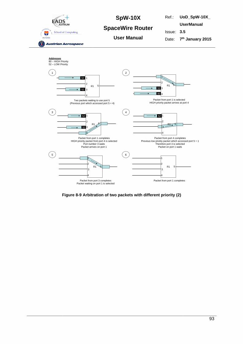
SpW-10X
SpaceWire Router
User Manual
Ref.: UoD_SpW-10X_
UserManual
Issue: 3.5
Date: 7th January 2015
93
R12
5
1
352
4
52
R1
25
1
352
4
Two packets waiting to use port 5
(Previous port which accessed port 5 = 4)
Packet from port 1 is selected
HIGH priority packet arrives at port 4
R12
5
1
3
4
Packet from port 1 completes
HIGH priority packet from port 4 is selected
Port number 3 waits
Packet arrives on port 1
R1
25
1
3
4
Packet from port 4 completes
Previous low priotity packet which accessed port 5 = 1
Therefore port 3 is selected
Packet on port 1 waits
1 2
3 4
Addresses
80 – HIGH Priority
52 – LOW Priority
80
52
52
R1
25
1
3
4
Packet from port 3 completes
Packet waiting on port 1 is selected
5
R1
25
1
3
4
Packet from port 1 completes
6
52
Figure 8-9 Arbitration of two packets with different priority (2)
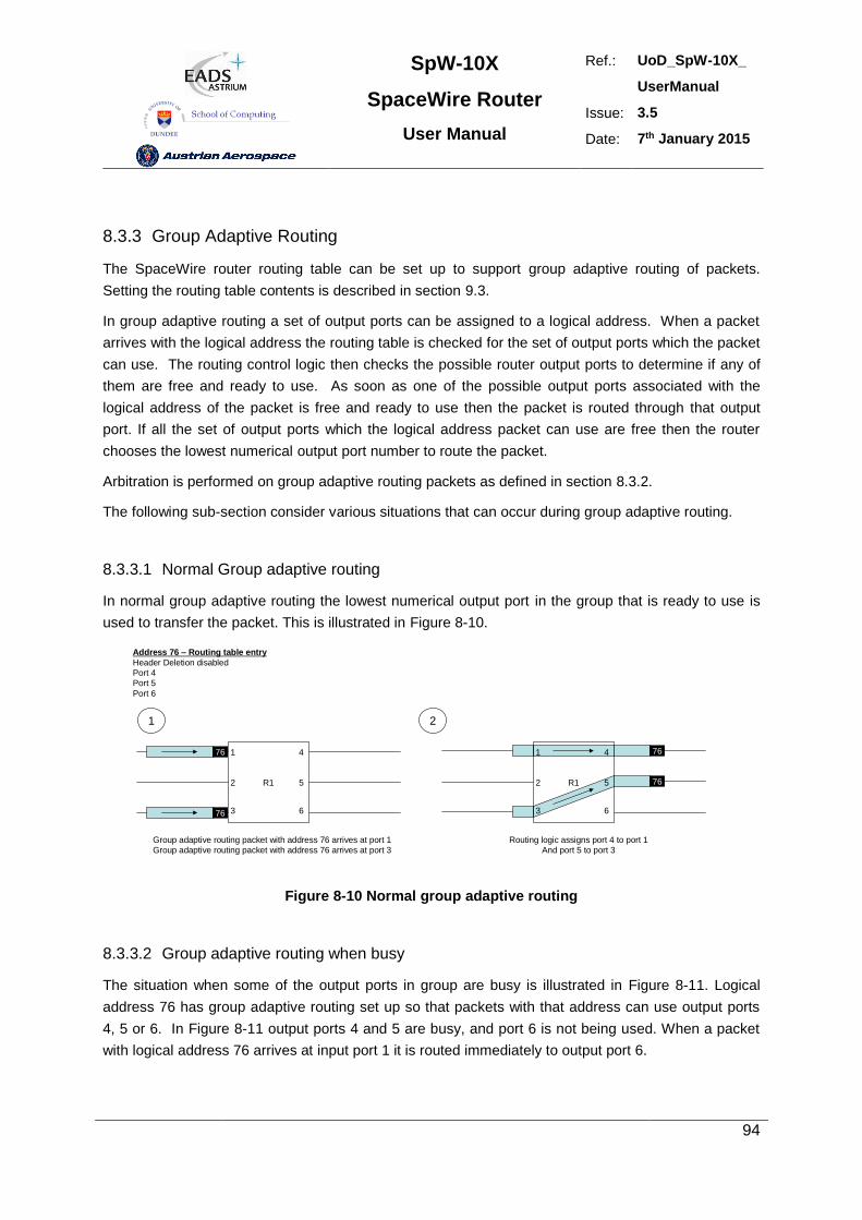
SpW-10X
SpaceWire Router
User Manual
Ref.: UoD_SpW-10X_
UserManual
Issue: 3.5
Date: 7th January 2015
94
8.3.3 Group Adaptive Routing
The SpaceWire router routing table can be set up to support group adaptive routing of packets.
Setting the routing table contents is described in section 9.3.
In group adaptive routing a set of output ports can be assigned to a logical address. When a packet
arrives with the logical address the routing table is checked for the set of output ports which the packet
can use. The routing control logic then checks the possible router output ports to determine if any of
them are free and ready to use. As soon as one of the possible output ports associated with the
logical address of the packet is free and ready to use then the packet is routed through that output
port. If all the set of output ports which the logical address packet can use are free then the router
chooses the lowest numerical output port number to route the packet.
Arbitration is performed on group adaptive routing packets as defined in section 8.3.2.
The following sub-section consider various situations that can occur during group adaptive routing.
8.3.3.1 Normal Group adaptive routing
In normal group adaptive routing the lowest numerical output port in the group that is ready to use is
used to transfer the packet. This is illustrated in Figure 8-10.
R1
1
2
3
4
5
6
76
76
R1
1
2
3
4
5
6
Group adaptive routing packet with address 76 arrives at port 1
Group adaptive routing packet with address 76 arrives at port 3
Routing logic assigns port 4 to port 1
And port 5 to port 3
Address 76 – Routing table entry
Header Deletion disabled
Port 4
Port 5
Port 6
76
76
1 2
Figure 8-10 Normal group adaptive routing
8.3.3.2 Group adaptive routing when busy
The situation when some of the output ports in group are busy is illustrated in Figure 8-11. Logical
address 76 has group adaptive routing set up so that packets with that address can use output ports
4, 5 or 6. In Figure 8-11 output ports 4 and 5 are busy, and port 6 is not being used. When a packet
with logical address 76 arrives at input port 1 it is routed immediately to output port 6.
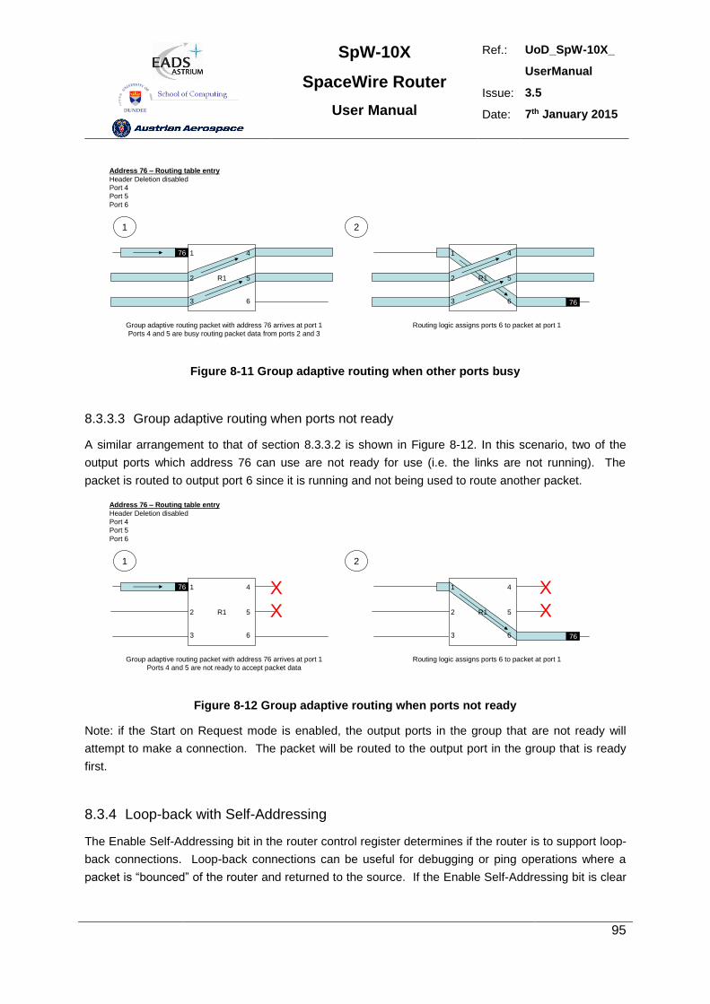
SpW-10X
SpaceWire Router
User Manual
Ref.: UoD_SpW-10X_
UserManual
Issue: 3.5
Date: 7th January 2015
95
R1
1
2
3
4
5
6
76
Group adaptive routing packet with address 76 arrives at port 1
Ports 4 and 5 are busy routing packet data from ports 2 and 3
Address 76 – Routing table entry
Header Deletion disabled
Port 4
Port 5
Port 6
1 2
R1
1
2
3
4
5
6 76
Routing logic assigns ports 6 to packet at port 1
Figure 8-11 Group adaptive routing when other ports busy
8.3.3.3 Group adaptive routing when ports not ready
A similar arrangement to that of section 8.3.3.2 is shown in Figure 8-12. In this scenario, two of the
output ports which address 76 can use are not ready for use (i.e. the links are not running). The
packet is routed to output port 6 since it is running and not being used to route another packet.
R1
1
2
3
4
5
6
76
Group adaptive routing packet with address 76 arrives at port 1
Ports 4 and 5 are not ready to accept packet data
Address 76 – Routing table entry
Header Deletion disabled
Port 4
Port 5
Port 6
1 2
R1
1
2
3
4
5
6 76
Routing logic assigns ports 6 to packet at port 1
X
X
X
X
Figure 8-12 Group adaptive routing when ports not ready
Note: if the Start on Request mode is enabled, the output ports in the group that are not ready will
attempt to make a connection. The packet will be routed to the output port in the group that is ready
first.
8.3.4 Loop-back with Self-Addressing
The Enable Self-Addressing bit in the router control register determines if the router is to support loop-
back connections. Loop-back connections can be useful for debugging or ping operations where a
packet is “bounced” of the router and returned to the source. If the Enable Self-Addressing bit is clear
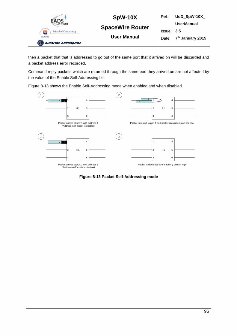
SpW-10X
SpaceWire Router
User Manual
Ref.: UoD_SpW-10X_
UserManual
Issue: 3.5
Date: 7th January 2015
96
then a packet that that is addressed to go out of the same port that it arrived on will be discarded and
a packet address error recorded.
Command reply packets which are returned through the same port they arrived on are not affected by
the value of the Enable Self-Addressing bit.
Figure 8-13 shows the Enable Self-Addressing mode when enabled and when disabled.
R1
1
2
3
4
5
6
1
R1
1
2
3
4
5
6
1 2
Packet arrives at port 1 with address 1
“Address-self mode” is enabled
Packet is routed to port 1 and packet data returns on link one
R1
1
2
3
4
5
6
1
R1
1
2
3
4
5
6
1 2
Packet arrives at port 1 with address 1
“Address-self” mode is disabled
Packet is discarded by the routing control logic
Figure 8-13 Packet Self-Addressing mode
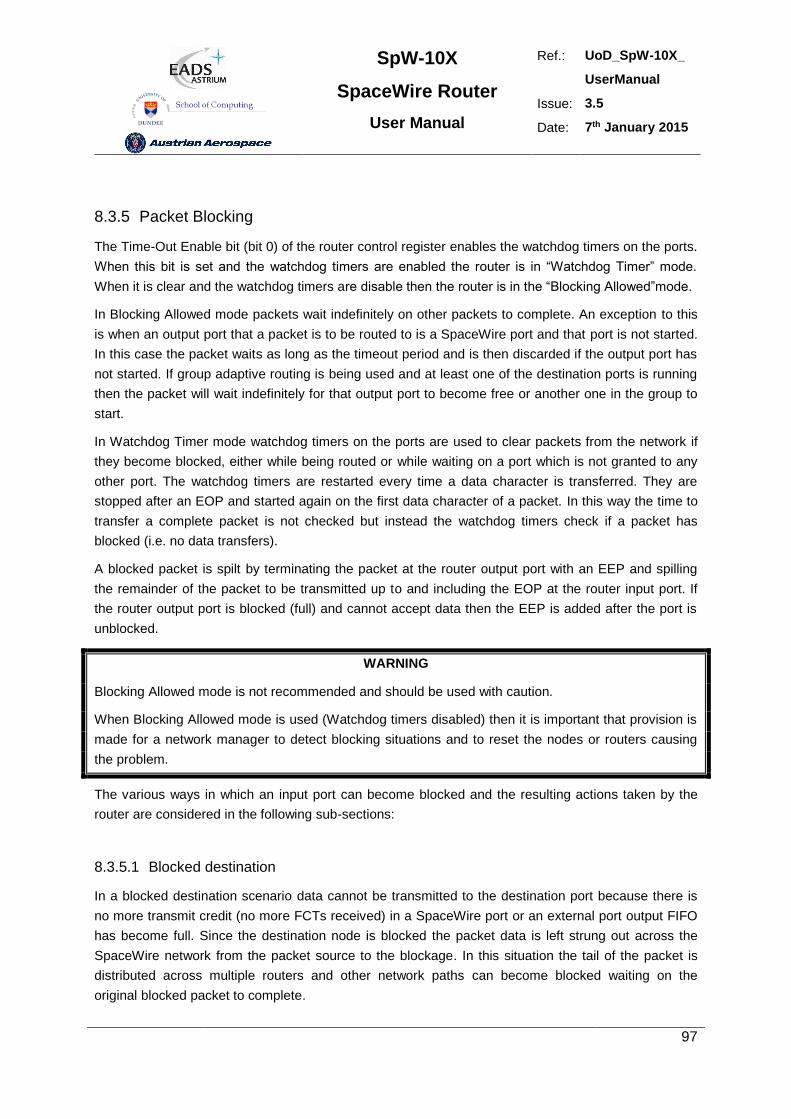
SpW-10X
SpaceWire Router
User Manual
Ref.: UoD_SpW-10X_
UserManual
Issue: 3.5
Date: 7th January 2015
97
8.3.5 Packet Blocking
The Time-Out Enable bit (bit 0) of the router control register enables the watchdog timers on the ports.
When this bit is set and the watchdog timers are enabled the router is in “Watchdog Timer” mode.
When it is clear and the watchdog timers are disable then the router is in the “Blocking Allowed”mode.
In Blocking Allowed mode packets wait indefinitely on other packets to complete. An exception to this
is when an output port that a packet is to be routed to is a SpaceWire port and that port is not started.
In this case the packet waits as long as the timeout period and is then discarded if the output port has
not started. If group adaptive routing is being used and at least one of the destination ports is running
then the packet will wait indefinitely for that output port to become free or another one in the group to
start.
In Watchdog Timer mode watchdog timers on the ports are used to clear packets from the network if
they become blocked, either while being routed or while waiting on a port which is not granted to any
other port. The watchdog timers are restarted every time a data character is transferred. They are
stopped after an EOP and started again on the first data character of a packet. In this way the time to
transfer a complete packet is not checked but instead the watchdog timers check if a packet has
blocked (i.e. no data transfers).
A blocked packet is spilt by terminating the packet at the router output port with an EEP and spilling
the remainder of the packet to be transmitted up to and including the EOP at the router input port. If
the router output port is blocked (full) and cannot accept data then the EEP is added after the port is
unblocked.
WARNING
Blocking Allowed mode is not recommended and should be used with caution.
When Blocking Allowed mode is used (Watchdog timers disabled) then it is important that provision is
made for a network manager to detect blocking situations and to reset the nodes or routers causing
the problem.
The various ways in which an input port can become blocked and the resulting actions taken by the
router are considered in the following sub-sections:
8.3.5.1 Blocked destination
In a blocked destination scenario data cannot be transmitted to the destination port because there is
no more transmit credit (no more FCTs received) in a SpaceWire port or an external port output FIFO
has become full. Since the destination node is blocked the packet data is left strung out across the
SpaceWire network from the packet source to the blockage. In this situation the tail of the packet is
distributed across multiple routers and other network paths can become blocked waiting on the
original blocked packet to complete.
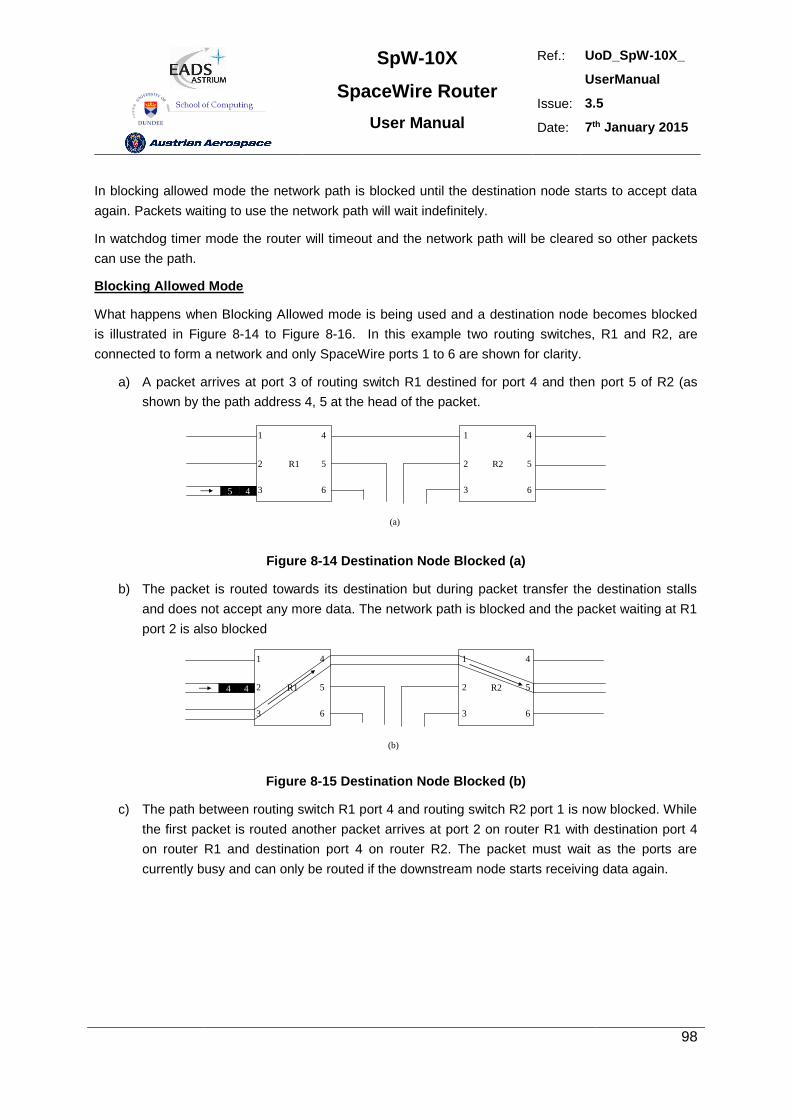
SpW-10X
SpaceWire Router
User Manual
Ref.: UoD_SpW-10X_
UserManual
Issue: 3.5
Date: 7th January 2015
98
In blocking allowed mode the network path is blocked until the destination node starts to accept data
again. Packets waiting to use the network path will wait indefinitely.
In watchdog timer mode the router will timeout and the network path will be cleared so other packets
can use the path.
Blocking Allowed Mode
What happens when Blocking Allowed mode is being used and a destination node becomes blocked
is illustrated in Figure 8-14 to Figure 8-16. In this example two routing switches, R1 and R2, are
connected to form a network and only SpaceWire ports 1 to 6 are shown for clarity.
a) A packet arrives at port 3 of routing switch R1 destined for port 4 and then port 5 of R2 (as
shown by the path address 4, 5 at the head of the packet.
R1
1
2
3
4
5
6
(a)
45
R2
1 4
2
3
5
6
Figure 8-14 Destination Node Blocked (a)
b) The packet is routed towards its destination but during packet transfer the destination stalls
and does not accept any more data. The network path is blocked and the packet waiting at R1
port 2 is also blocked
R1
1
2
3
4
5
6
(b)
R2
1 4
2
3
5
6
44
Figure 8-15 Destination Node Blocked (b)
c) The path between routing switch R1 port 4 and routing switch R2 port 1 is now blocked. While
the first packet is routed another packet arrives at port 2 on router R1 with destination port 4
on router R1 and destination port 4 on router R2. The packet must wait as the ports are
currently busy and can only be routed if the downstream node starts receiving data again.
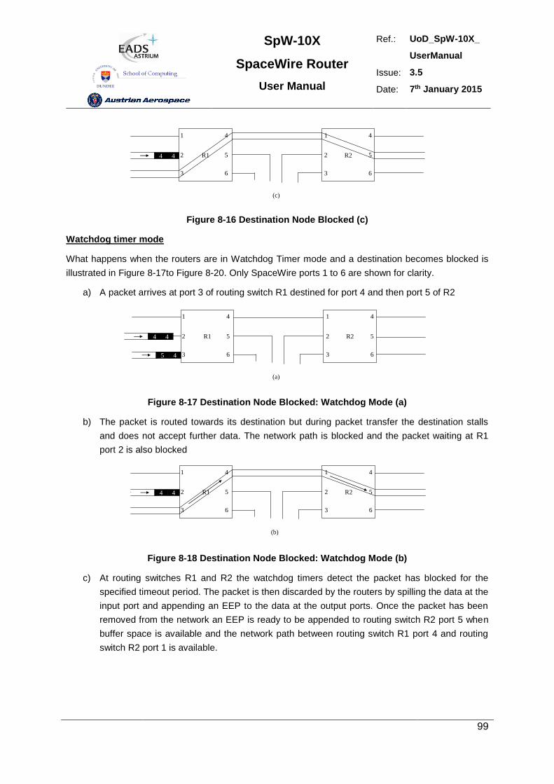
SpW-10X
SpaceWire Router
User Manual
Ref.: UoD_SpW-10X_
UserManual
Issue: 3.5
Date: 7th January 2015
99
R1
1
2
3
4
5
6
(c)
R2
1 4
2
3
5
6
44
Figure 8-16 Destination Node Blocked (c)
Watchdog timer mode
What happens when the routers are in Watchdog Timer mode and a destination becomes blocked is
illustrated in Figure 8-17to Figure 8-20. Only SpaceWire ports 1 to 6 are shown for clarity.
a) A packet arrives at port 3 of routing switch R1 destined for port 4 and then port 5 of R2
R1
1
2
3
4
5
6
(a)
45
R2
1 4
2
3
5
6
44
Figure 8-17 Destination Node Blocked: Watchdog Mode (a)
b) The packet is routed towards its destination but during packet transfer the destination stalls
and does not accept further data. The network path is blocked and the packet waiting at R1
port 2 is also blocked
R1
1
2
3
4
5
6
(b)
R2
1 4
2
3
5
6
44
Figure 8-18 Destination Node Blocked: Watchdog Mode (b)
c) At routing switches R1 and R2 the watchdog timers detect the packet has blocked for the
specified timeout period. The packet is then discarded by the routers by spilling the data at the
input port and appending an EEP to the data at the output ports. Once the packet has been
removed from the network an EEP is ready to be appended to routing switch R2 port 5 when
buffer space is available and the network path between routing switch R1 port 4 and routing
switch R2 port 1 is available.
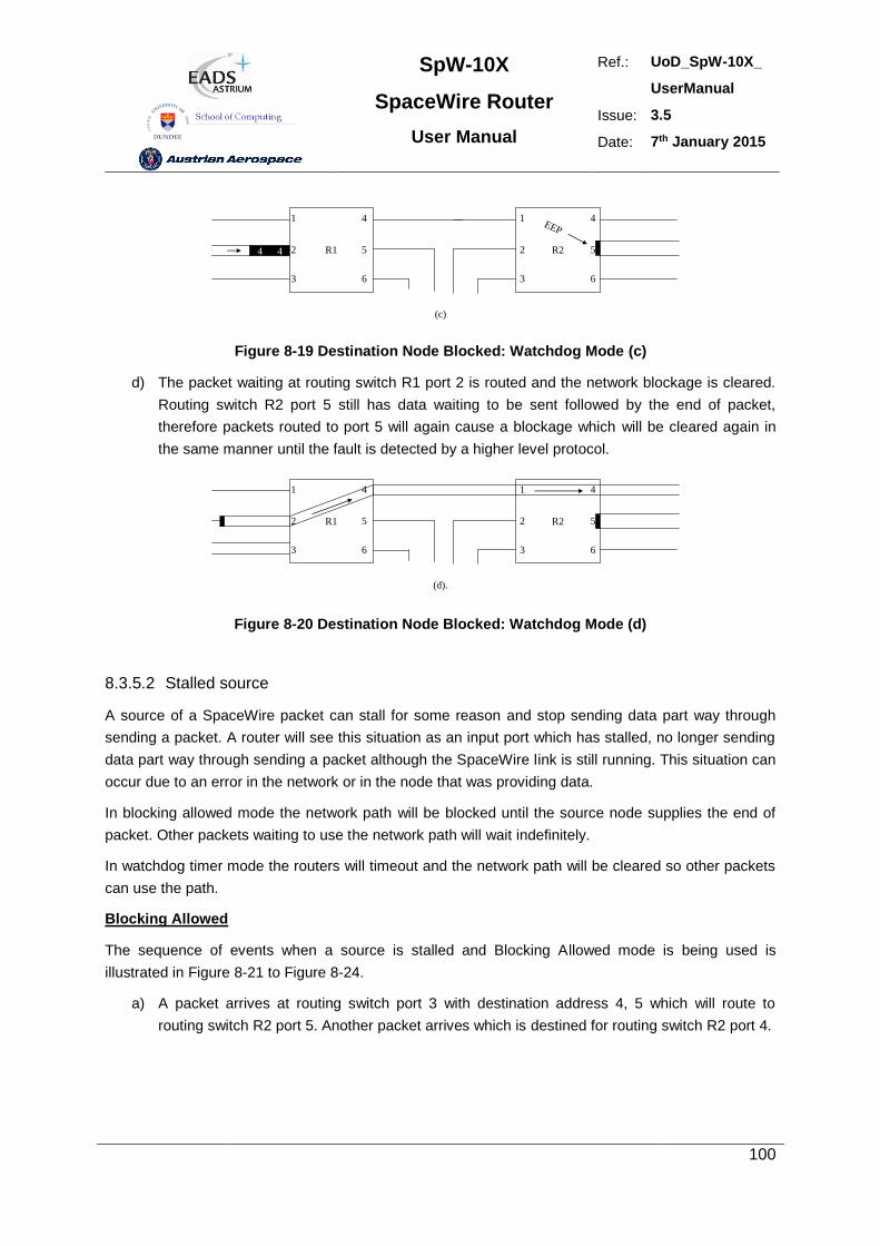
SpW-10X
SpaceWire Router
User Manual
Ref.: UoD_SpW-10X_
UserManual
Issue: 3.5
Date: 7th January 2015
100
1
2
3
4
5
6
(c)
1 4
2
3
5
6
44
EEP
R1 R2
Figure 8-19 Destination Node Blocked: Watchdog Mode (c)
d) The packet waiting at routing switch R1 port 2 is routed and the network blockage is cleared.
Routing switch R2 port 5 still has data waiting to be sent followed by the end of packet,
therefore packets routed to port 5 will again cause a blockage which will be cleared again in
the same manner until the fault is detected by a higher level protocol.
R1
1
2
3
4
5
6
(d).
1 4
2
3
5
6
R2
Figure 8-20 Destination Node Blocked: Watchdog Mode (d)
8.3.5.2 Stalled source
A source of a SpaceWire packet can stall for some reason and stop sending data part way through
sending a packet. A router will see this situation as an input port which has stalled, no longer sending
data part way through sending a packet although the SpaceWire link is still running. This situation can
occur due to an error in the network or in the node that was providing data.
In blocking allowed mode the network path will be blocked until the source node supplies the end of
packet. Other packets waiting to use the network path will wait indefinitely.
In watchdog timer mode the routers will timeout and the network path will be cleared so other packets
can use the path.
Blocking Allowed
The sequence of events when a source is stalled and Blocking Allowed mode is being used is
illustrated in Figure 8-21 to Figure 8-24.
a) A packet arrives at routing switch port 3 with destination address 4, 5 which will route to
routing switch R2 port 5. Another packet arrives which is destined for routing switch R2 port 4.
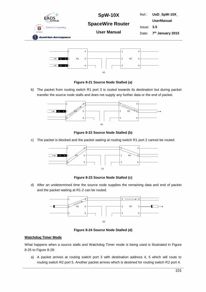
SpW-10X
SpaceWire Router
User Manual
Ref.: UoD_SpW-10X_
UserManual
Issue: 3.5
Date: 7th January 2015
101
R1
1
2
3
4
5
6
(a)
45
R2
1 4
2
3
5
6
44
Figure 8-21 Source Node Stalled (a)
b) The packet from routing switch R1 port 3 is routed towards its destination but during packet
transfer the source node stalls and does not supply any further data or the end of packet.
R1
1
2
3
4
5
6
(b)
R2
1 4
2
3
5
6
44
Figure 8-22 Source Node Stalled (b)
c) The packet is blocked and the packet waiting at routing switch R1 port 2 cannot be routed.
R1
1
2
3
4
5
6
(c)
R2
1 4
2
3
5
6
44
Figure 8-23 Source Node Stalled (c)
d) After an undetermined time the source node supplies the remaining data and end of packet
and the packet waiting at R1-2 can be routed.
R1
1
2
3
4
5
6
(d)
R2
1 4
2
3
5
6
Figure 8-24 Source Node Stalled (d)
Watchdog Timer Mode
What happens when a source stalls and Watchdog Timer mode is being used is illustrated in Figure
8-25 to Figure 8-28:
a) A packet arrives at routing switch port 3 with destination address 4, 5 which will route to
routing switch R2 port 5. Another packet arrives which is destined for routing switch R2 port 4.
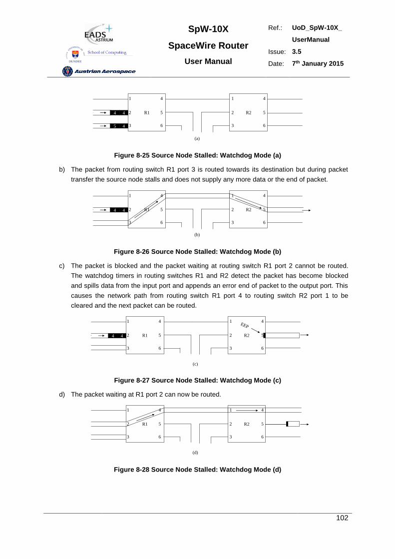
SpW-10X
SpaceWire Router
User Manual
Ref.: UoD_SpW-10X_
UserManual
Issue: 3.5
Date: 7th January 2015
102
R1
1
2
3
4
5
6
(a)
45
R2
1 4
2
3
5
6
44
Figure 8-25 Source Node Stalled: Watchdog Mode (a)
b) The packet from routing switch R1 port 3 is routed towards its destination but during packet
transfer the source node stalls and does not supply any more data or the end of packet.
R1
1
2
3
4
5
6
(b)
R2
1 4
2
3
5
6
44
Figure 8-26 Source Node Stalled: Watchdog Mode (b)
c) The packet is blocked and the packet waiting at routing switch R1 port 2 cannot be routed.
The watchdog timers in routing switches R1 and R2 detect the packet has become blocked
and spills data from the input port and appends an error end of packet to the output port. This
causes the network path from routing switch R1 port 4 to routing switch R2 port 1 to be
cleared and the next packet can be routed.
R1
1
2
3
4
5
6
(c)
R2
1 4
2
3
5
6
44
EEP
Figure 8-27 Source Node Stalled: Watchdog Mode (c)
d) The packet waiting at R1 port 2 can now be routed.
R1
1
2
3
4
5
6
(d)
R2
1 4
2
3
5
6
Figure 8-28 Source Node Stalled: Watchdog Mode (d)
SpW-10X
SpaceWire Router
User Manual
Ref.: UoD_SpW-10X_
UserManual
Issue: 3.5
Date: 7th January 2015
103
8.3.5.3 Waiting for an output port
When a packet arrives at an input port of the SpW-10X router is has to wait to be forwarded to an
output port. How long the packet waits will depend on whether the router is in Blocking Allowed or
Watchdog Timer mode and on what the output ports are doing. Various situations are considered
below:
In Blocking Allowed mode packets will wait indefinitely to be granted access to an output port. There is
one exception to this: if the destination port is a SpaceWire port and the port is not started the packet
will only wait as long as the timeout period and then the router will spill the packet. If group adaptive
routing is being used and at least one of the output ports in the group is running then the packet will
wait indefinitely until the running port is ready, even if one or more of the other ports are not started.
In Watchdog Timer mode there are several possible cases which are considered below.
Output port not running: If a packet arrives at an input port of the SpW-10X router and the output
port that it is to be routed to is not running, the router will wait for the output port to start for the
watchdog timeout period and will then spill the packet if the link has not started. If Start on Request
has been enabled the router will wait for the watchdog timer timeout interval for the output port to start.
The packet will be routed to the output port as soon as it starts and a connection is made. If the port
does not start before the end of the timeout interval then the waiting packet will be spilt.\
Output port running and not busy: If a packet arrives at an input port on the SpW-10X router and
the output port that it is to be router to is running but not currently sending a packet, then the newly
arrived packet will be routed immediately.
Output port running and busy: If a packet arrives at an input port on the SpW-10X router and the
output port that it is to be router to is running and currently sending a packet the newly arrived packet
will wait indefinitely for the output port to finish sending is current packet. The waiting packet will then
be sent. This approach is taken because it is clear that the output port is operational and not blocked,
so the newly arrived packet will wait for the current packet to complete transfer.
Output port in a group, not running: A packet arrives at an input port of the SpW-10 router and the
packet has a logical address addressing a group of possible output ports. If all of the ports in the group
are not running, the router will wait for an output port to start for the watchdog timeout period and will
then spill the packet if one of the links has not started. If Start on Request is enabled then the router
will try to start all the ports in the group. The packet will be router to whichever port starts first. If none
of the ports starts before the timeout interval has expired the packet will be spilt.
Output port in a group with one port running and not busy: If a packet arrives at an input port
with a group logical address and one of the output ports in the group is running and not currently busy
sending a packet, the newly arrived packet will be routed to that output port immediately.
Output port in a group with one port busy: If a packet arrives with a group logical address and one
of the output ports in the group is busy sending a packet and the other output ports in the group are
not running, the SpW-10X will wait indefinitely to send the packet, whether or not Start on Request is
enabled. When the busy output port finished sending its packet the waiting packet will be sent.
SpW-10X
SpaceWire Router
User Manual
Ref.: UoD_SpW-10X_
UserManual
Issue: 3.5
Date: 7th January 2015
104
WARNING
Packets can timeout and be spilled in a SpaceWire network without the destination receiving any
notification of this. Packets with errors (e.g. parity error) can arrive at a destination terminated by an
EEP. In a very special case it is also possible to receive an error free packet terminated by an EEP. It
is important that the destination node is able to handle these cases.
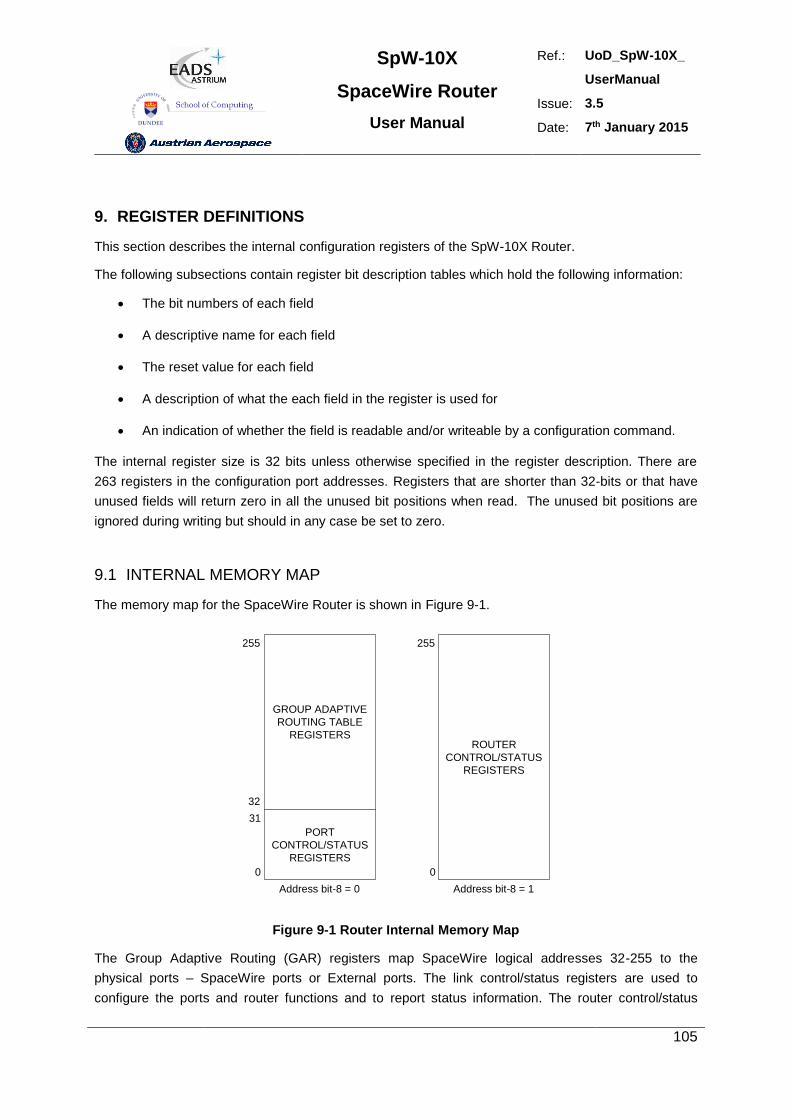
SpW-10X
SpaceWire Router
User Manual
Ref.: UoD_SpW-10X_
UserManual
Issue: 3.5
Date: 7th January 2015
105
9. REGISTER DEFINITIONS
This section describes the internal configuration registers of the SpW-10X Router.
The following subsections contain register bit description tables which hold the following information:
The bit numbers of each field
A descriptive name for each field
The reset value for each field
A description of what the each field in the register is used for
An indication of whether the field is readable and/or writeable by a configuration command.
The internal register size is 32 bits unless otherwise specified in the register description. There are
263 registers in the configuration port addresses. Registers that are shorter than 32-bits or that have
unused fields will return zero in all the unused bit positions when read. The unused bit positions are
ignored during writing but should in any case be set to zero.
9.1 INTERNAL MEMORY MAP
The memory map for the SpaceWire Router is shown in Figure 9-1.
GROUP ADAPTIVE
ROUTING TABLE
REGISTERS
PORT
CONTROL/STATUS
REGISTERS
ROUTER
CONTROL/STATUS
REGISTERS
Address bit-8 = 0 Address bit-8 = 1
255
32
31
0
255
0
Figure 9-1 Router Internal Memory Map
The Group Adaptive Routing (GAR) registers map SpaceWire logical addresses 32-255 to the
physical ports – SpaceWire ports or External ports. The link control/status registers are used to
configure the ports and router functions and to report status information. The router control/status
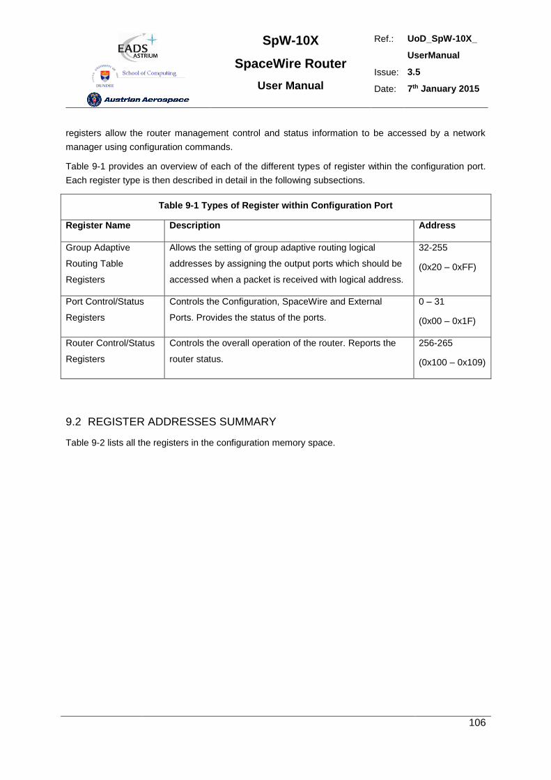
SpW-10X
SpaceWire Router
User Manual
Ref.: UoD_SpW-10X_
UserManual
Issue: 3.5
Date: 7th January 2015
106
registers allow the router management control and status information to be accessed by a network
manager using configuration commands.
Table 9-1 provides an overview of each of the different types of register within the configuration port.
Each register type is then described in detail in the following subsections.
Table 9-1 Types of Register within Configuration Port
Register Name Description Address
Group Adaptive
Routing Table
Registers
Allows the setting of group adaptive routing logical
addresses by assigning the output ports which should be
accessed when a packet is received with logical address.
32-255
(0x20 – 0xFF)
Port Control/Status
Registers
Controls the Configuration, SpaceWire and External
Ports. Provides the status of the ports.
0 – 31
(0x00 – 0x1F)
Router Control/Status
Registers
Controls the overall operation of the router. Reports the
router status.
256-265
(0x100 – 0x109)
9.2 REGISTER ADDRESSES SUMMARY
Table 9-2 lists all the registers in the configuration memory space.
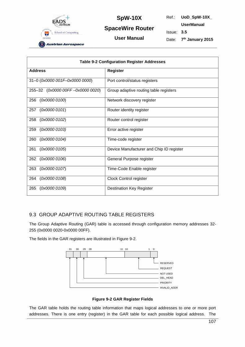
SpW-10X
SpaceWire Router
User Manual
Ref.: UoD_SpW-10X_
UserManual
Issue: 3.5
Date: 7th January 2015
107
Table 9-2 Configuration Register Addresses
Address Register
31–0 (0x0000 001F–0x0000 0000) Port control/status registers
255–32 (0x0000 00FF –0x0000 0020) Group adaptive routing table registers
256 (0x0000 0100) Network discovery register
257 (0x0000 0101) Router identity register
258 (0x0000 0102) Router control register
259 (0x0000 0103) Error active register
260 (0x0000 0104) Time-code register
261 (0x0000 0105) Device Manufacturer and Chip ID register
262 (0x0000 0106) General Purpose register
263 (0x0000 0107) Time-Code Enable register
264 (0x0000 0108) Clock Control register
265 (0x0000 0109) Destination Key Register
9.3 GROUP ADAPTIVE ROUTING TABLE REGISTERS
The Group Adaptive Routing (GAR) table is accessed through configuration memory addresses 32-
255 (0x0000 0020-0x0000 00FF).
The fields in the GAR registers are illustrated in Figure 9-2.
REQUEST
128293031
DEL_HEAD
PRIORITY
INVALID_ADDR
0
RESERVED
NOT USED
11 10
Figure 9-2 GAR Register Fields
The GAR table holds the routing table information that maps logical addresses to one or more port
addresses. There is one entry (register) in the GAR table for each possible logical address. The
SpW-10X
SpaceWire Router
User Manual
Ref.: UoD_SpW-10X_
UserManual
Issue: 3.5
Date: 7th January 2015
108
configuration memory address range of the GAR table is 32-255 (0x0000 0020 – 0x0000 00FF). The
configuration memory address corresponds to the logical address; hence the GAR table entry at
address 39 corresponds to logical address 39.
The logical address to port mapping is held in the REQUEST field. Each bit in this field represents a
physical output port; thus up to 28 possible output ports can be specified using the GAR register,
although only 10 ports (plus the configuration port) are provided in the SpW-10X. The configuration
port is port number 0, the SpaceWire ports are port numbers 1 to 8 and the External ports are ports 9
and 10. When a bit is set in the REQUEST field packets may be routed to the corresponding output
ports. The port number corresponds to the bit position in the GAR register. For example, if
configuration memory address 39 has bit 2 set then a packet with logical address 39 may be routed
out of port 2. If bits 2 and 4 are both set then the packet may be routed out of either port 2 or 4. Port
0, the configuration port, is a special port which can only be accessed using address 0 so this bit
position in the GAR table registers is reserved and will always be set to zero.
The DEL_HEAD bit, when set, causes the leading byte (header) of a packer to be deleted.
The PRIORITY bit determines the priority of the logical address when packets waiting at two input
ports wish to use the same output port (1 = high priority, 0 = low priority).
The INVALID_ADDR bit is set to indicate that the corresponding logical address is not valid.
Table 9-3 describes each field in the GAR register.
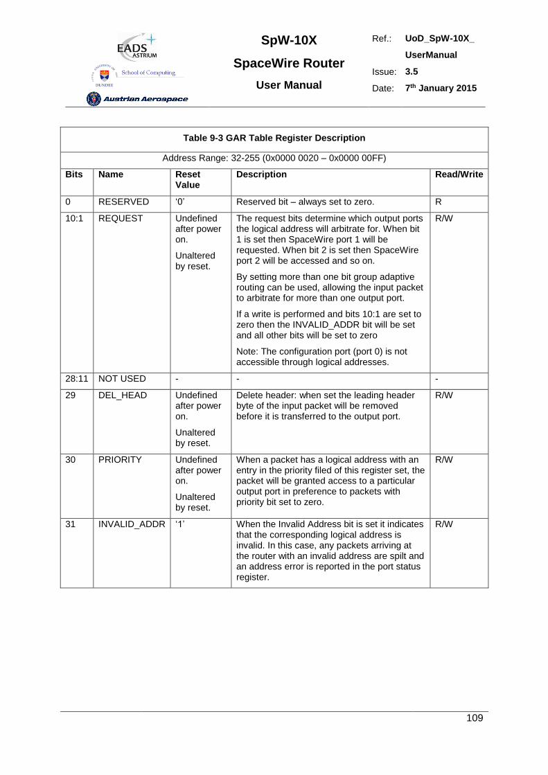
SpW-10X
SpaceWire Router
User Manual
Ref.: UoD_SpW-10X_
UserManual
Issue: 3.5
Date: 7th January 2015
109
Table 9-3 GAR Table Register Description
Address Range: 32-255 (0x0000 0020 – 0x0000 00FF)
Bits Name Reset Value
Description Read/Write
0 RESERVED ‘0’ Reserved bit – always set to zero. R
10:1 REQUEST Undefined after power on.
Unaltered by reset.
The request bits determine which output ports the logical address will arbitrate for. When bit 1 is set then SpaceWire port 1 will be requested. When bit 2 is set then SpaceWire port 2 will be accessed and so on.
By setting more than one bit group adaptive routing can be used, allowing the input packet to arbitrate for more than one output port.
If a write is performed and bits 10:1 are set to zero then the INVALID_ADDR bit will be set and all other bits will be set to zero
Note: The configuration port (port 0) is not accessible through logical addresses.
R/W
28:11 NOT USED - - -
29 DEL_HEAD Undefined after power on.
Unaltered by reset.
Delete header: when set the leading header byte of the input packet will be removed before it is transferred to the output port.
R/W
30 PRIORITY Undefined after power on.
Unaltered by reset.
When a packet has a logical address with an entry in the priority filed of this register set, the packet will be granted access to a particular output port in preference to packets with priority bit set to zero.
R/W
31 INVALID_ADDR ‘1’ When the Invalid Address bit is set it indicates that the corresponding logical address is invalid. In this case, any packets arriving at the router with an invalid address are spilt and an address error is reported in the port status register.
R/W
SpW-10X
SpaceWire Router
User Manual
Ref.: UoD_SpW-10X_
UserManual
Issue: 3.5
Date: 7th January 2015
110
WARNING
Care must be taken when setting a the routing tables to avoid a possible infinite loop. For example if
there is a SpaceWire link made between two ports of a single router and a logical address routes a
packet out of one of these ports then that packet will arrive back at the router, and be routed back out
of the port again. Depending on the size of the packet it may block because it cannot get access to the
output port the second time around as the tail of the packet is still being fed to the output port. In this
case the blockage will cause a timeout (when watchdog timer mode set – see section 8.3.5) and the
packet will be spilt. If the packet is a small packet it could continually circle around the loop. A
SpaceWire network architecture and configuration should be checked for possible loops for all logical
addresses being used. Unused logical addresses should NOT be configured in the SpW-10X routing
tables so that a packet arriving at a router with an invalid (unused) logical address will be spilt
immediately.
9.4 PORT CONTROL/STATUS REGISTERS
The port control/status registers address range is 0 – 31 (0x0000 0000 – 0x0000 001F )
The port control/status registers provide the means to configure and control the ports of the router and
for reading the status of each port. There is a port control/status register for each SpaceWire port,
each External port and for the configuration port. The address in configuration memory space of a
port control/status register reflects the physical address of the port. For example, the register for port
0, the configuration port, is at address 0, and the register for a SpaceWire port number 3 is at address
3. Each port control/status register is a 32-bit register.
The fields within the port control/status register depend on the type of port that it is attached to. All port
control/status registers have fields for port type and current port connection. These generic fields are
described first followed by the specific fields for the configuration port, SpaceWire ports and External
ports.
Port control/status register bits 31:24 are generic to all ports. Register bits 23:0 are specific to the type
of port to which the register is attached.
9.4.1 Generic port control/status register fields.
The configuration port control/status fields are described in Table 9-4.
Table 9-4 Configuration Port Control/Status Register Fields
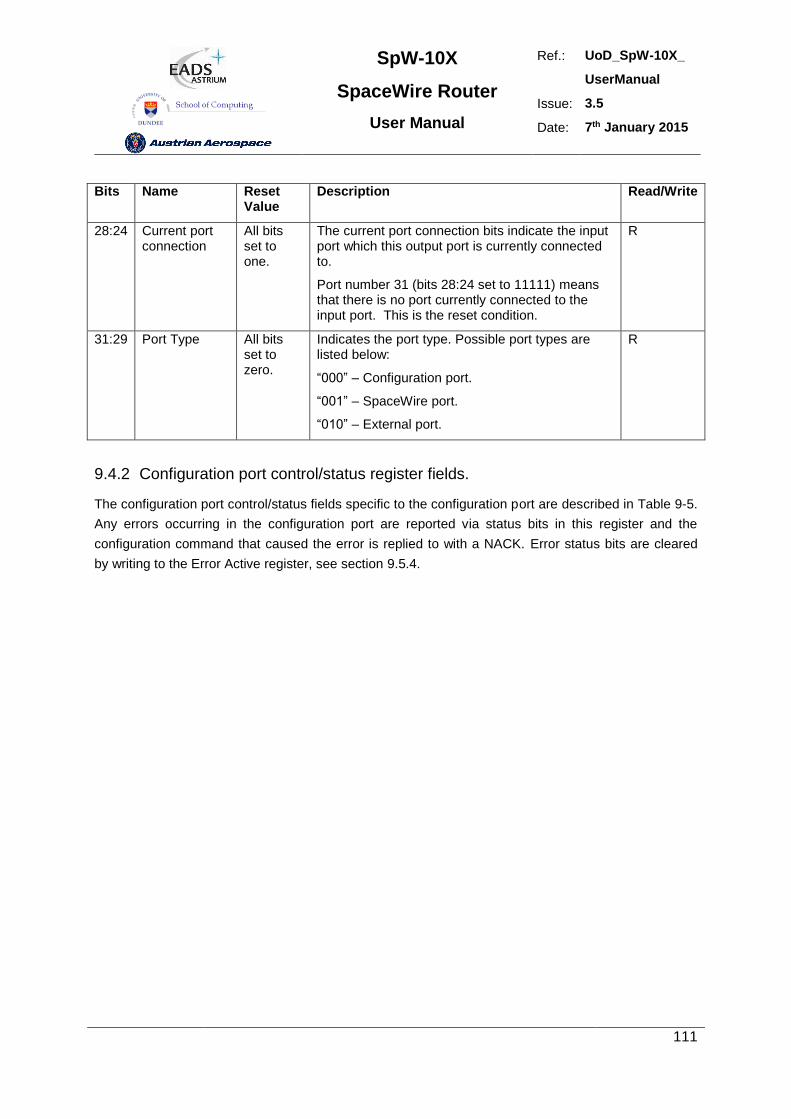
SpW-10X
SpaceWire Router
User Manual
Ref.: UoD_SpW-10X_
UserManual
Issue: 3.5
Date: 7th January 2015
111
Bits Name Reset Value
Description Read/Write
28:24 Current port connection
All bits set to one.
The current port connection bits indicate the input port which this output port is currently connected to.
Port number 31 (bits 28:24 set to 11111) means that there is no port currently connected to the input port. This is the reset condition.
R
31:29 Port Type All bits set to zero.
Indicates the port type. Possible port types are listed below:
“000” – Configuration port.
“001” – SpaceWire port.
“010” – External port.
R
9.4.2 Configuration port control/status register fields.
The configuration port control/status fields specific to the configuration port are described in Table 9-5.
Any errors occurring in the configuration port are reported via status bits in this register and the
configuration command that caused the error is replied to with a NACK. Error status bits are cleared
by writing to the Error Active register, see section 9.5.4.
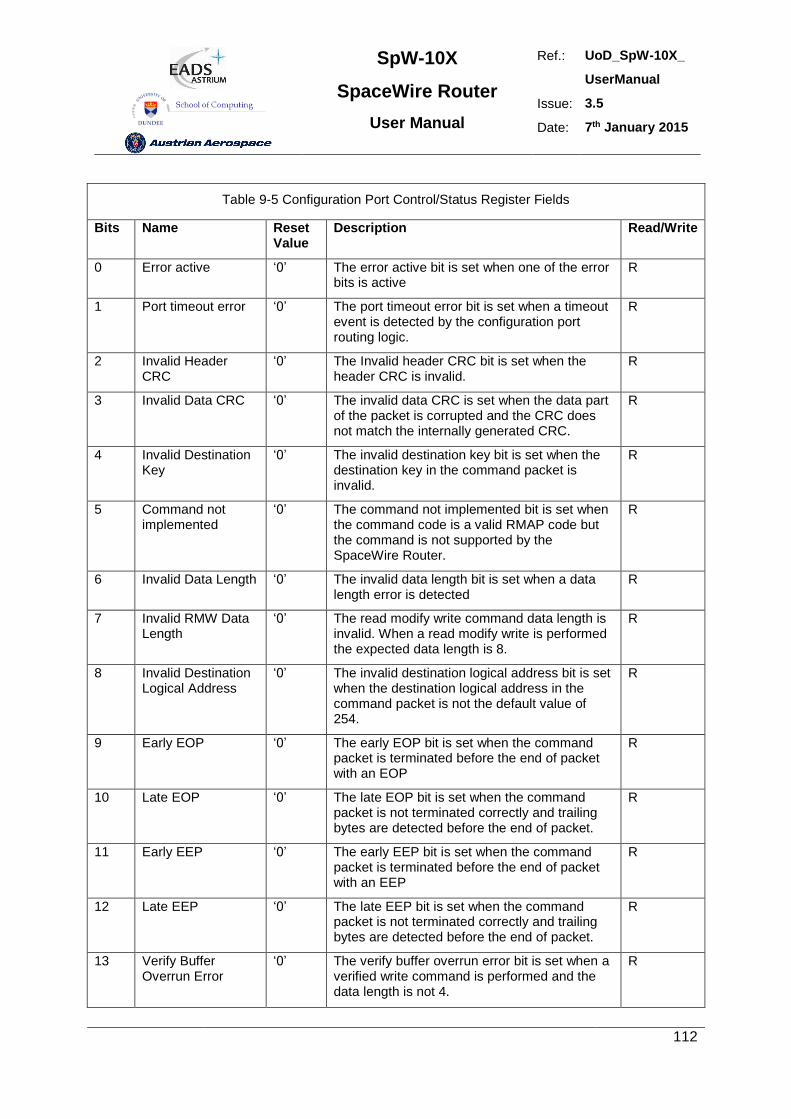
SpW-10X
SpaceWire Router
User Manual
Ref.: UoD_SpW-10X_
UserManual
Issue: 3.5
Date: 7th January 2015
112
Table 9-5 Configuration Port Control/Status Register Fields
Bits Name Reset Value
Description Read/Write
0 Error active ‘0’ The error active bit is set when one of the error bits is active
R
1 Port timeout error ‘0’ The port timeout error bit is set when a timeout event is detected by the configuration port routing logic.
R
2 Invalid Header CRC
‘0’ The Invalid header CRC bit is set when the header CRC is invalid.
R
3 Invalid Data CRC ‘0’ The invalid data CRC is set when the data part of the packet is corrupted and the CRC does not match the internally generated CRC.
R
4 Invalid Destination Key
‘0’ The invalid destination key bit is set when the destination key in the command packet is invalid.
R
5 Command not implemented
‘0’ The command not implemented bit is set when the command code is a valid RMAP code but the command is not supported by the SpaceWire Router.
R
6 Invalid Data Length ‘0’ The invalid data length bit is set when a data length error is detected
R
7 Invalid RMW Data Length
‘0’ The read modify write command data length is invalid. When a read modify write is performed the expected data length is 8.
R
8 Invalid Destination Logical Address
‘0’ The invalid destination logical address bit is set when the destination logical address in the command packet is not the default value of 254.
R
9 Early EOP ‘0’ The early EOP bit is set when the command packet is terminated before the end of packet with an EOP
R
10 Late EOP ‘0’ The late EOP bit is set when the command packet is not terminated correctly and trailing bytes are detected before the end of packet.
R
11 Early EEP ‘0’ The early EEP bit is set when the command packet is terminated before the end of packet with an EEP
R
12 Late EEP ‘0’ The late EEP bit is set when the command packet is not terminated correctly and trailing bytes are detected before the end of packet.
R
13 Verify Buffer Overrun Error
‘0’ The verify buffer overrun error bit is set when a verified write command is performed and the data length is not 4.
R
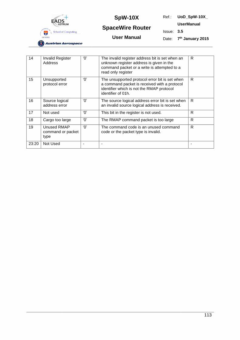
SpW-10X
SpaceWire Router
User Manual
Ref.: UoD_SpW-10X_
UserManual
Issue: 3.5
Date: 7th January 2015
113
14 Invalid Register Address
‘0’ The invalid register address bit is set when an unknown register address is given in the command packet or a write is attempted to a read only register
R
15 Unsupported protocol error
‘0’ The unsupported protocol error bit is set when a command packet is received with a protocol identifier which is not the RMAP protocol identifier of 01h.
R
16 Source logical address error
‘0’ The source logical address error bit is set when an invalid source logical address is received.
R
17 Not used ‘0’ This bit in the register is not used. R
18 Cargo too large ‘0’ The RMAP command packet is too large R
19 Unused RMAP command or packet type
‘0’ The command code is an unused command code or the packet type is invalid.
R
23:20 Not Used - - -
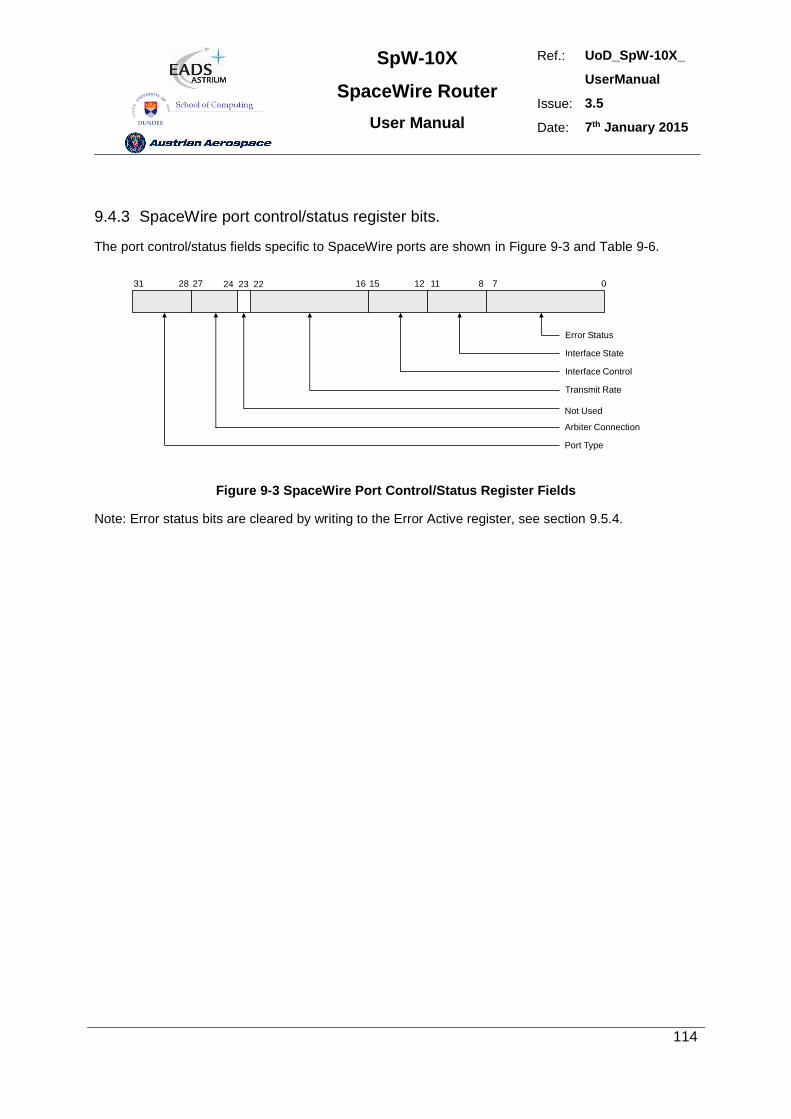
SpW-10X
SpaceWire Router
User Manual
Ref.: UoD_SpW-10X_
UserManual
Issue: 3.5
Date: 7th January 2015
114
9.4.3 SpaceWire port control/status register bits.
The port control/status fields specific to SpaceWire ports are shown in Figure 9-3 and Table 9-6.
Error Status
0711 815 12162227 2431 28
Interface State
Interface Control
Transmit Rate
Arbiter Connection
Port Type
Not Used
23
Figure 9-3 SpaceWire Port Control/Status Register Fields
Note: Error status bits are cleared by writing to the Error Active register, see section 9.5.4.
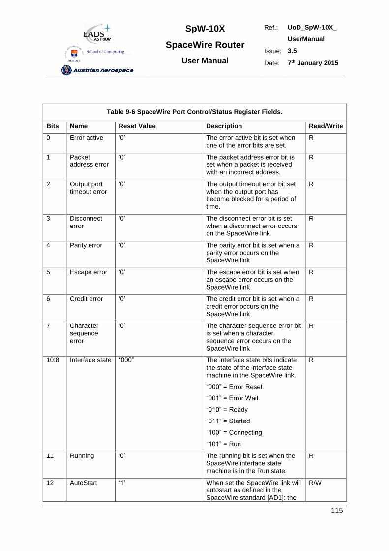
SpW-10X
SpaceWire Router
User Manual
Ref.: UoD_SpW-10X_
UserManual
Issue: 3.5
Date: 7th January 2015
115
Table 9-6 SpaceWire Port Control/Status Register Fields.
Bits Name Reset Value Description Read/Write
0 Error active ‘0’ The error active bit is set when one of the error bits are set.
R
1 Packet address error
‘0’ The packet address error bit is set when a packet is received with an incorrect address.
R
2 Output port timeout error
‘0’ The output timeout error bit set when the output port has become blocked for a period of time.
R
3 Disconnect error
‘0’ The disconnect error bit is set when a disconnect error occurs on the SpaceWire link
R
4 Parity error ‘0’ The parity error bit is set when a parity error occurs on the SpaceWire link
R
5 Escape error ‘0’ The escape error bit is set when an escape error occurs on the SpaceWire link
R
6 Credit error ‘0’ The credit error bit is set when a credit error occurs on the SpaceWire link
R
7 Character sequence error
‘0’ The character sequence error bit is set when a character sequence error occurs on the SpaceWire link
R
10:8 Interface state “000” The interface state bits indicate the state of the interface state machine in the SpaceWire link.
“000” = Error Reset
“001” = Error Wait
“010” = Ready
“011” = Started
“100” = Connecting
“101” = Run
R
11 Running ‘0’ The running bit is set when the SpaceWire interface state machine is in the Run state.
R
12 AutoStart ‘1’ When set the SpaceWire link will autostart as defined in the SpaceWire standard [AD1]: the
R/W
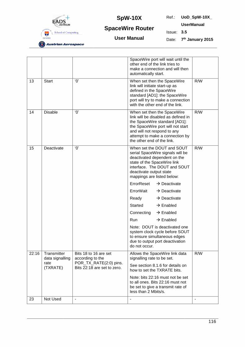
SpW-10X
SpaceWire Router
User Manual
Ref.: UoD_SpW-10X_
UserManual
Issue: 3.5
Date: 7th January 2015
116
SpaceWire port will wait until the other end of the link tries to make a connection and will then automatically start.
13 Start ‘0’ When set then the SpaceWire link will initiate start-up as defined in the SpaceWire standard [AD1]: the SpaceWire port will try to make a connection with the other end of the link.
R/W
14 Disable ‘0’ When set then the SpaceWire link will be disabled as defined in the SpaceWire standard [AD1]: the SpaceWire port will not start and will not respond to any attempt to make a connection by the other end of the link.
R/W
15 Deactivate ‘0’ When set the DOUT and SOUT serial SpaceWire signals will be deactivated dependent on the state of the SpaceWire link interface. The DOUT and SOUT deactivate output state mappings are listed below:
ErrorReset Deactivate
ErrorWait Deactivate
Ready Deactivate
Started Enabled
Connecting Enabled
Run Enabled
Note: DOUT is deactivated one system clock cycle before SOUT to ensure simultaneous edges due to output port deactivation do not occur.
R/W
22:16 Transmitter data signalling rate (TXRATE)
Bits 18 to 16 are set according to the POR_TX_RATE(2:0) pins. Bits 22:18 are set to zero.
Allows the SpaceWire link data signalling rate to be set.
See section 8.1.6 for details on how to set the TXRATE bits.
Note: bits 22:16 must not be set to all ones. Bits 22:16 must not be set to give a transmit rate of less than 2 Mbits/s.
R/W
23 Not Used - - -
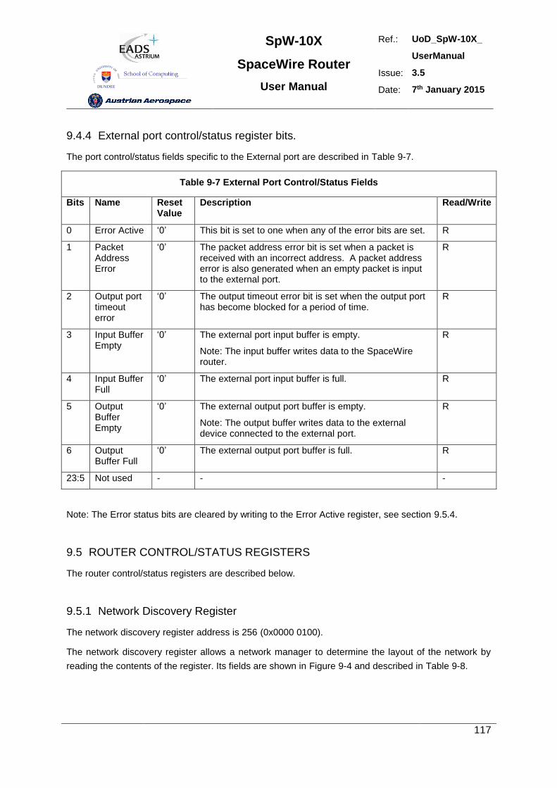
SpW-10X
SpaceWire Router
User Manual
Ref.: UoD_SpW-10X_
UserManual
Issue: 3.5
Date: 7th January 2015
117
9.4.4 External port control/status register bits.
The port control/status fields specific to the External port are described in Table 9-7.
Table 9-7 External Port Control/Status Fields
Bits Name Reset Value
Description Read/Write
0 Error Active ‘0’ This bit is set to one when any of the error bits are set. R
1 Packet Address Error
‘0’ The packet address error bit is set when a packet is received with an incorrect address. A packet address error is also generated when an empty packet is input to the external port.
R
2 Output port timeout error
‘0’ The output timeout error bit is set when the output port has become blocked for a period of time.
R
3 Input Buffer Empty
‘0’ The external port input buffer is empty.
Note: The input buffer writes data to the SpaceWire router.
R
4 Input Buffer Full
‘0’ The external port input buffer is full. R
5 Output Buffer Empty
‘0’ The external output port buffer is empty.
Note: The output buffer writes data to the external device connected to the external port.
R
6 Output Buffer Full
‘0’ The external output port buffer is full. R
23:5 Not used - - -
Note: The Error status bits are cleared by writing to the Error Active register, see section 9.5.4.
9.5 ROUTER CONTROL/STATUS REGISTERS
The router control/status registers are described below.
9.5.1 Network Discovery Register
The network discovery register address is 256 (0x0000 0100).
The network discovery register allows a network manager to determine the layout of the network by
reading the contents of the register. Its fields are shown in Figure 9-4 and described in Table 9-8.
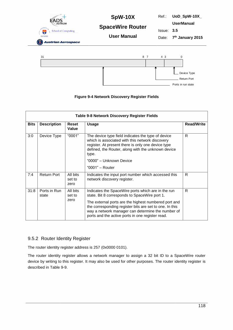
SpW-10X
SpaceWire Router
User Manual
Ref.: UoD_SpW-10X_
UserManual
Issue: 3.5
Date: 7th January 2015
118
Device Type
07 38 4
Return Port
Ports in run state
31
Figure 9-4 Network Discovery Register Fields
Table 9-8 Network Discovery Register Fields
Bits Description Reset Value
Usage Read/Write
3:0 Device Type “0001” The device type field indicates the type of device which is associated with this network discovery register. At present there is only one device type defined, the Router, along with the unknown device type.
“0000” – Unknown Device
“0001” – Router
R
7:4 Return Port All bits set to zero
Indicates the input port number which accessed this network discovery register.
R
31:8 Ports in Run state
All bits set to zero
Indicates the SpaceWire ports which are in the run state. Bit 8 corresponds to SpaceWire port 1.
The external ports are the highest numbered port and the corresponding register bits are set to one. In this way a network manager can determine the number of ports and the active ports in one register read.
R
9.5.2 Router Identity Register
The router identity register address is 257 (0x0000 0101).
The router identity register allows a network manager to assign a 32 bit ID to a SpaceWire router
device by writing to this register. It may also be used for other purposes. The router identity register is
described in Table 9-9.
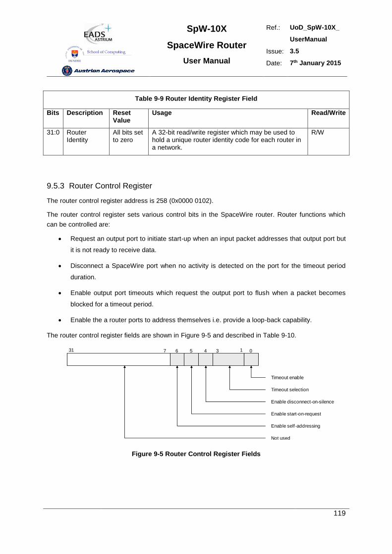
SpW-10X
SpaceWire Router
User Manual
Ref.: UoD_SpW-10X_
UserManual
Issue: 3.5
Date: 7th January 2015
119
Table 9-9 Router Identity Register Field
Bits Description Reset Value
Usage Read/Write
31:0 Router Identity
All bits set to zero
A 32-bit read/write register which may be used to hold a unique router identity code for each router in a network.
R/W
9.5.3 Router Control Register
The router control register address is 258 (0x0000 0102).
The router control register sets various control bits in the SpaceWire router. Router functions which
can be controlled are:
Request an output port to initiate start-up when an input packet addresses that output port but
it is not ready to receive data.
Disconnect a SpaceWire port when no activity is detected on the port for the timeout period
duration.
Enable output port timeouts which request the output port to flush when a packet becomes
blocked for a timeout period.
Enable the a router ports to address themselves i.e. provide a loop-back capability.
The router control register fields are shown in Figure 9-5 and described in Table 9-10.
Timeout enable
05 3 1431 6
Timeout selection
Enable disconnect-on-silence
Enable start-on-request
Not used
Enable self -addressing
7
Figure 9-5 Router Control Register Fields
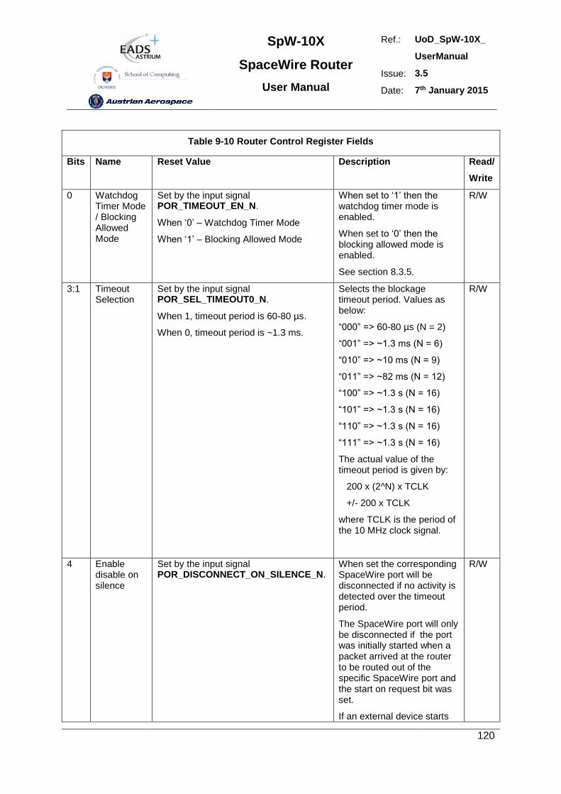
SpW-10X
SpaceWire Router
User Manual
Ref.: UoD_SpW-10X_
UserManual
Issue: 3.5
Date: 7th January 2015
120
Table 9-10 Router Control Register Fields
Bits Name Reset Value Description Read/
Write
0 Watchdog Timer Mode / Blocking Allowed Mode
Set by the input signal POR_TIMEOUT_EN_N.
When ‘0’ – Watchdog Timer Mode
When ‘1’ – Blocking Allowed Mode
When set to ‘1’ then the watchdog timer mode is enabled.
When set to ‘0’ then the blocking allowed mode is enabled.
See section 8.3.5.
R/W
3:1 Timeout Selection
Set by the input signal POR_SEL_TIMEOUT0_N.
When 1, timeout period is 60-80 µs.
When 0, timeout period is ~1.3 ms.
Selects the blockage timeout period. Values as below:
“000” => 60-80 µs (N = 2)
“001” => ~1.3 ms (N = 6)
“010” => ~10 ms (N = 9)
“011” => ~82 ms (N = 12)
“100” => ~1.3 s (N = 16)
“101” => ~1.3 s (N = 16)
“110” => ~1.3 s (N = 16)
“111” => ~1.3 s (N = 16)
The actual value of the timeout period is given by:
200 x (2^N) x TCLK
+/- 200 x TCLK
where TCLK is the period of the 10 MHz clock signal.
R/W
4 Enable disable on silence
Set by the input signal POR_DISCONNECT_ON_SILENCE_N.
When set the corresponding SpaceWire port will be disconnected if no activity is detected over the timeout period.
The SpaceWire port will only be disconnected if the port was initially started when a packet arrived at the router to be routed out of the specific SpaceWire port and the start on request bit was set.
If an external device starts
R/W
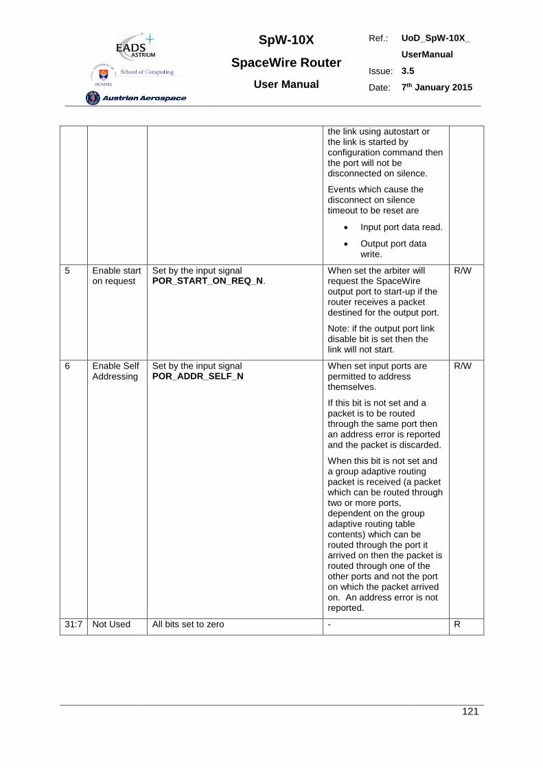
SpW-10X
SpaceWire Router
User Manual
Ref.: UoD_SpW-10X_
UserManual
Issue: 3.5
Date: 7th January 2015
121
the link using autostart or the link is started by configuration command then the port will not be disconnected on silence.
Events which cause the disconnect on silence timeout to be reset are
Input port data read.
Output port data write.
5 Enable start on request
Set by the input signal POR_START_ON_REQ_N.
When set the arbiter will request the SpaceWire output port to start-up if the router receives a packet destined for the output port.
Note: if the output port link disable bit is set then the link will not start.
R/W
6 Enable Self Addressing
Set by the input signal POR_ADDR_SELF_N
When set input ports are permitted to address themselves.
If this bit is not set and a packet is to be routed through the same port then an address error is reported and the packet is discarded.
When this bit is not set and a group adaptive routing packet is received (a packet which can be routed through two or more ports, dependent on the group adaptive routing table contents) which can be routed through the port it arrived on then the packet is routed through one of the other ports and not the port on which the packet arrived on. An address error is not reported.
R/W
31:7 Not Used All bits set to zero - R
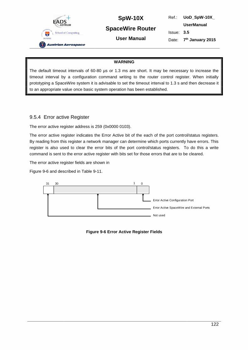
SpW-10X
SpaceWire Router
User Manual
Ref.: UoD_SpW-10X_
UserManual
Issue: 3.5
Date: 7th January 2015
122
WARNING
The default timeout intervals of 60-80 µs or 1.3 ms are short. It may be necessary to increase the
timeout interval by a configuration command writing to the router control register. When initially
prototyping a SpaceWire system it is advisable to set the timeout interval to 1.3 s and then decrease it
to an appropriate value once basic system operation has been established.
9.5.4 Error active Register
The error active register address is 259 (0x0000 0103).
The error active register indicates the Error Active bit of the each of the port control/status registers.
By reading from this register a network manager can determine which ports currently have errors. This
register is also used to clear the error bits of the port control/status registers. To do this a write
command is sent to the error active register with bits set for those errors that are to be cleared.
The error active register fields are shown in
Figure 9-6 and described in Table 9-11.
Error Active Configuration Port
030 131
Error Active SpaceWire and External Ports
Not used
Figure 9-6 Error Active Register Fields
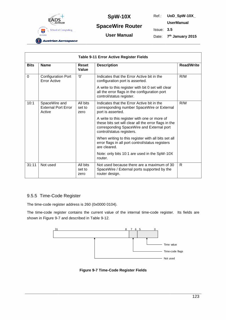
SpW-10X
SpaceWire Router
User Manual
Ref.: UoD_SpW-10X_
UserManual
Issue: 3.5
Date: 7th January 2015
123
Table 9-11 Error Active Register Fields
Bits Name Reset Value
Description Read/Write
0 Configuration Port Error Active
‘0’ Indicates that the Error Active bit in the configuration port is asserted.
A write to this register with bit 0 set will clear all the error flags in the configuration port control/status register.
R/W
10:1 SpaceWire and External Port Error Active
All bits set to zero
Indicates that the Error Active bit in the corresponding number SpaceWire or External port is asserted.
A write to this register with one or more of these bits set will clear all the error flags in the corresponding SpaceWire and External port control/status registers.
When writing to this register with all bits set all error flags in all port control/status registers are cleared.
Note: only bits 10:1 are used in the SpW-10X router.
R/W
31:11 Not used All bits set to zero
Not used because there are a maximum of 30 SpaceWire / External ports supported by the router design.
R
9.5.5 Time-Code Register
The time-code register address is 260 (0x0000 0104).
The time-code register contains the current value of the internal time-code register. Its fields are
shown in Figure 9-7 and described in Table 9-12.
Time value
31
Time-code flags
7 6 0
Not used
58
Figure 9-7 Time-Code Register Fields
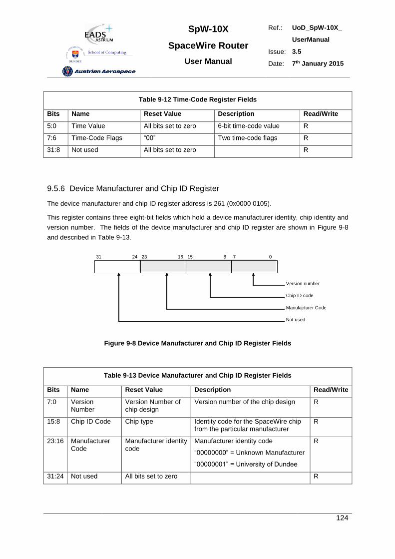
SpW-10X
SpaceWire Router
User Manual
Ref.: UoD_SpW-10X_
UserManual
Issue: 3.5
Date: 7th January 2015
124
Table 9-12 Time-Code Register Fields
Bits Name Reset Value Description Read/Write
5:0 Time Value All bits set to zero 6-bit time-code value R
7:6 Time-Code Flags “00” Two time-code flags R
31:8 Not used All bits set to zero R
9.5.6 Device Manufacturer and Chip ID Register
The device manufacturer and chip ID register address is 261 (0x0000 0105).
This register contains three eight-bit fields which hold a device manufacturer identity, chip identity and
version number. The fields of the device manufacturer and chip ID register are shown in Figure 9-8
and described in Table 9-13.
Version number
31
Chip ID code
Manufacturer Code
24 23 16 15 8 7 0
Not used
Figure 9-8 Device Manufacturer and Chip ID Register Fields
Table 9-13 Device Manufacturer and Chip ID Register Fields
Bits Name Reset Value Description Read/Write
7:0 Version Number
Version Number of chip design
Version number of the chip design R
15:8 Chip ID Code Chip type Identity code for the SpaceWire chip from the particular manufacturer
R
23:16 Manufacturer Code
Manufacturer identity code
Manufacturer identity code
“00000000” = Unknown Manufacturer
“00000001” = University of Dundee
R
31:24 Not used All bits set to zero R
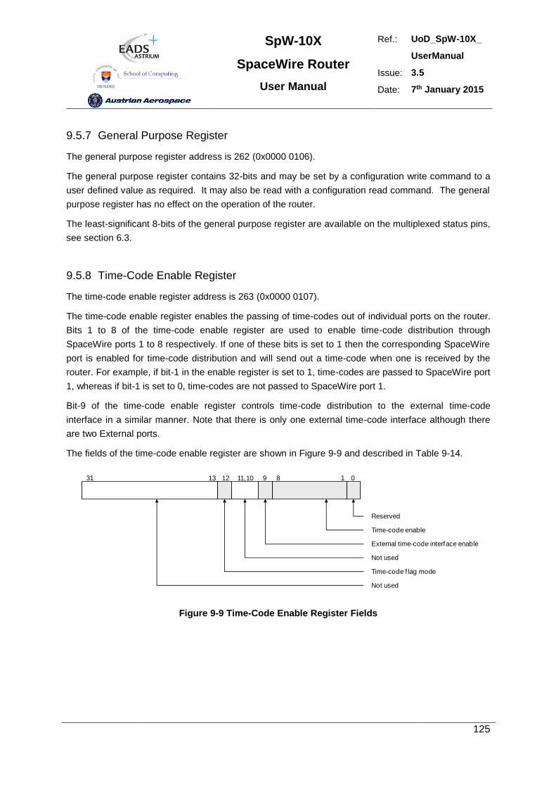
SpW-10X
SpaceWire Router
User Manual
Ref.: UoD_SpW-10X_
UserManual
Issue: 3.5
Date: 7th January 2015
125
9.5.7 General Purpose Register
The general purpose register address is 262 (0x0000 0106).
The general purpose register contains 32-bits and may be set by a configuration write command to a
user defined value as required. It may also be read with a configuration read command. The general
purpose register has no effect on the operation of the router.
The least-significant 8-bits of the general purpose register are available on the multiplexed status pins,
see section 6.3.
9.5.8 Time-Code Enable Register
The time-code enable register address is 263 (0x0000 0107).
The time-code enable register enables the passing of time-codes out of individual ports on the router.
Bits 1 to 8 of the time-code enable register are used to enable time-code distribution through
SpaceWire ports 1 to 8 respectively. If one of these bits is set to 1 then the corresponding SpaceWire
port is enabled for time-code distribution and will send out a time-code when one is received by the
router. For example, if bit-1 in the enable register is set to 1, time-codes are passed to SpaceWire port
1, whereas if bit-1 is set to 0, time-codes are not passed to SpaceWire port 1.
Bit-9 of the time-code enable register controls time-code distribution to the external time-code
interface in a similar manner. Note that there is only one external time-code interface although there
are two External ports.
The fields of the time-code enable register are shown in Figure 9-9 and described in Table 9-14.
Reserved
31 8
External time-code interface enable
913 01
Not used
Time-code enable
12 11,10
Not used
Time-code f lag mode
Figure 9-9 Time-Code Enable Register Fields
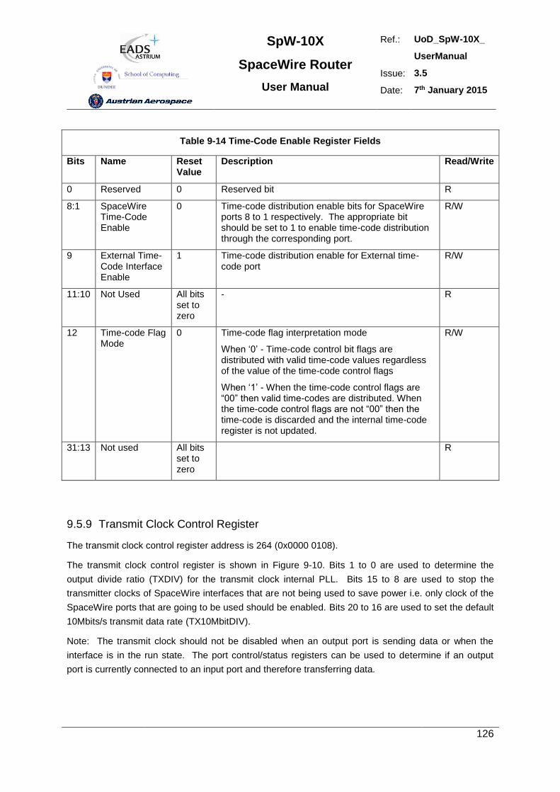
SpW-10X
SpaceWire Router
User Manual
Ref.: UoD_SpW-10X_
UserManual
Issue: 3.5
Date: 7th January 2015
126
Table 9-14 Time-Code Enable Register Fields
Bits Name Reset Value
Description Read/Write
0 Reserved 0 Reserved bit R
8:1 SpaceWire Time-Code Enable
0 Time-code distribution enable bits for SpaceWire ports 8 to 1 respectively. The appropriate bit should be set to 1 to enable time-code distribution through the corresponding port.
R/W
9 External Time-Code Interface Enable
1 Time-code distribution enable for External time-code port
R/W
11:10 Not Used All bits set to zero
- R
12 Time-code Flag Mode
0 Time-code flag interpretation mode
When ‘0’ - Time-code control bit flags are distributed with valid time-code values regardless of the value of the time-code control flags
When ‘1’ - When the time-code control flags are “00” then valid time-codes are distributed. When the time-code control flags are not “00” then the time-code is discarded and the internal time-code register is not updated.
R/W
31:13 Not used All bits set to zero
R
9.5.9 Transmit Clock Control Register
The transmit clock control register address is 264 (0x0000 0108).
The transmit clock control register is shown in Figure 9-10. Bits 1 to 0 are used to determine the
output divide ratio (TXDIV) for the transmit clock internal PLL. Bits 15 to 8 are used to stop the
transmitter clocks of SpaceWire interfaces that are not being used to save power i.e. only clock of the
SpaceWire ports that are going to be used should be enabled. Bits 20 to 16 are used to set the default
10Mbits/s transmit data rate (TX10MbitDIV).
Note: The transmit clock should not be disabled when an output port is sending data or when the
interface is in the run state. The port control/status registers can be used to determine if an output
port is currently connected to an input port and therefore transferring data.
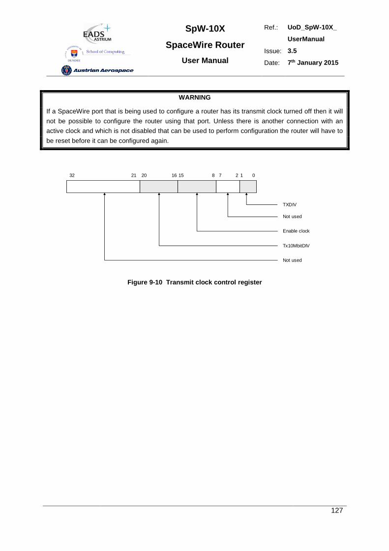
SpW-10X
SpaceWire Router
User Manual
Ref.: UoD_SpW-10X_
UserManual
Issue: 3.5
Date: 7th January 2015
127
WARNING
If a SpaceWire port that is being used to configure a router has its transmit clock turned off then it will
not be possible to configure the router using that port. Unless there is another connection with an
active clock and which is not disabled that can be used to perform configuration the router will have to
be reset before it can be configured again.
TXDIV
015 8
Not used
127
Enable clock
1620
Tx10MbitDIV
2132
Not used
Figure 9-10 Transmit clock control register
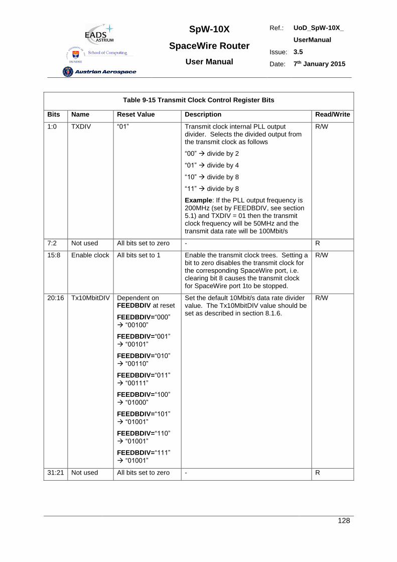
SpW-10X
SpaceWire Router
User Manual
Ref.: UoD_SpW-10X_
UserManual
Issue: 3.5
Date: 7th January 2015
128
Table 9-15 Transmit Clock Control Register Bits
Bits Name Reset Value Description Read/Write
1:0 TXDIV “01” Transmit clock internal PLL output divider. Selects the divided output from the transmit clock as follows
“00” divide by 2
“01” divide by 4
“10” divide by 8
“11” divide by 8
Example: If the PLL output frequency is 200MHz (set by FEEDBDIV, see section 5.1) and TXDIV = 01 then the transmit clock frequency will be 50MHz and the transmit data rate will be 100Mbit/s
R/W
7:2 Not used All bits set to zero - R
15:8 Enable clock All bits set to 1 Enable the transmit clock trees. Setting a bit to zero disables the transmit clock for the corresponding SpaceWire port, i.e. clearing bit 8 causes the transmit clock for SpaceWire port 1to be stopped.
R/W
20:16 Tx10MbitDIV Dependent on FEEDBDIV at reset
FEEDBDIV=“000”
“00100”
FEEDBDIV=“001”
“00101”
FEEDBDIV=“010”
“00110”
FEEDBDIV=“011”
“00111”
FEEDBDIV=“100”
“01000”
FEEDBDIV=“101”
“01001”
FEEDBDIV=“110”
“01001”
FEEDBDIV=“111”
“01001”
Set the default 10Mbit/s data rate divider value. The Tx10MbitDIV value should be set as described in section 8.1.6.
R/W
31:21 Not used All bits set to zero - R
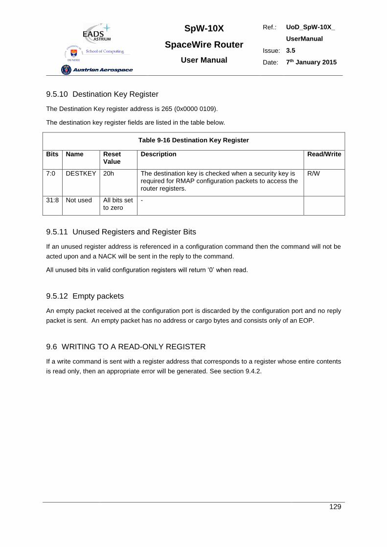
SpW-10X
SpaceWire Router
User Manual
Ref.: UoD_SpW-10X_
UserManual
Issue: 3.5
Date: 7th January 2015
129
9.5.10 Destination Key Register
The Destination Key register address is 265 (0x0000 0109).
The destination key register fields are listed in the table below.
Table 9-16 Destination Key Register
Bits Name Reset Value
Description Read/Write
7:0 DESTKEY 20h The destination key is checked when a security key is required for RMAP configuration packets to access the router registers.
R/W
31:8 Not used All bits set to zero
-
9.5.11 Unused Registers and Register Bits
If an unused register address is referenced in a configuration command then the command will not be
acted upon and a NACK will be sent in the reply to the command.
All unused bits in valid configuration registers will return ‘0’ when read.
9.5.12 Empty packets
An empty packet received at the configuration port is discarded by the configuration port and no reply
packet is sent. An empty packet has no address or cargo bytes and consists only of an EOP.
9.6 WRITING TO A READ-ONLY REGISTER
If a write command is sent with a register address that corresponds to a register whose entire contents
is read only, then an appropriate error will be generated. See section 9.4.2.
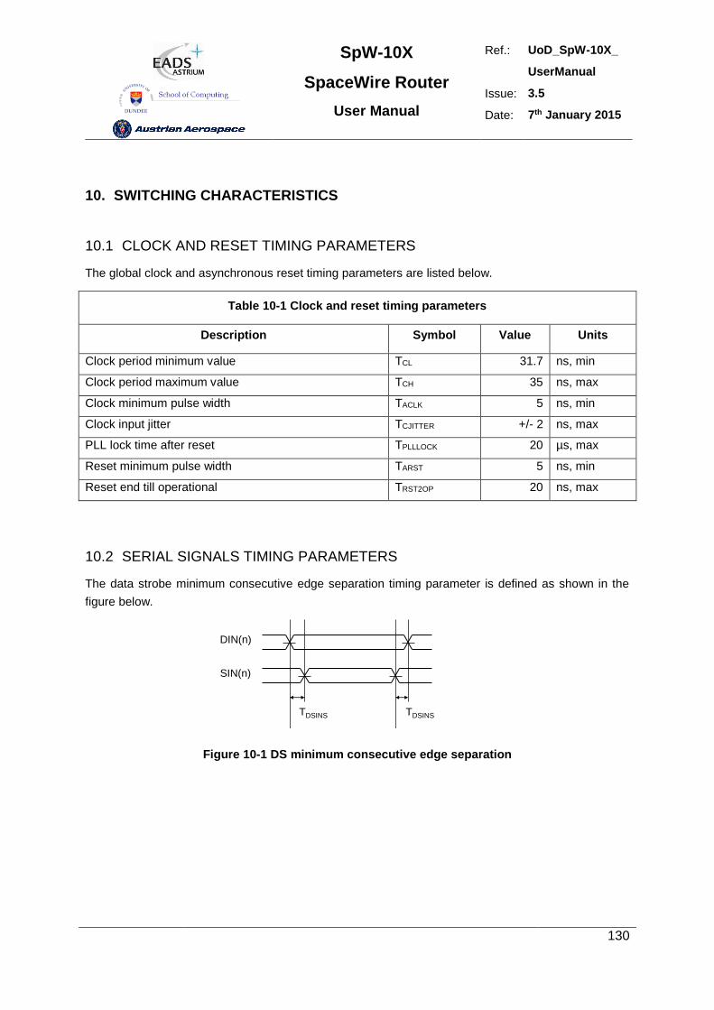
SpW-10X
SpaceWire Router
User Manual
Ref.: UoD_SpW-10X_
UserManual
Issue: 3.5
Date: 7th January 2015
130
10. SWITCHING CHARACTERISTICS
10.1 CLOCK AND RESET TIMING PARAMETERS
The global clock and asynchronous reset timing parameters are listed below.
Table 10-1 Clock and reset timing parameters
Description Symbol Value Units
Clock period minimum value TCL 31.7 ns, min
Clock period maximum value TCH 35 ns, max
Clock minimum pulse width TACLK 5 ns, min
Clock input jitter TCJITTER +/- 2 ns, max
PLL lock time after reset TPLLLOCK 20 µs, max
Reset minimum pulse width TARST 5 ns, min
Reset end till operational TRST2OP 20 ns, max
10.2 SERIAL SIGNALS TIMING PARAMETERS
The data strobe minimum consecutive edge separation timing parameter is defined as shown in the
figure below.
DIN(n)
SIN(n)
TDSINS TDSINS
TDSINS2
Figure 10-1 DS minimum consecutive edge separation
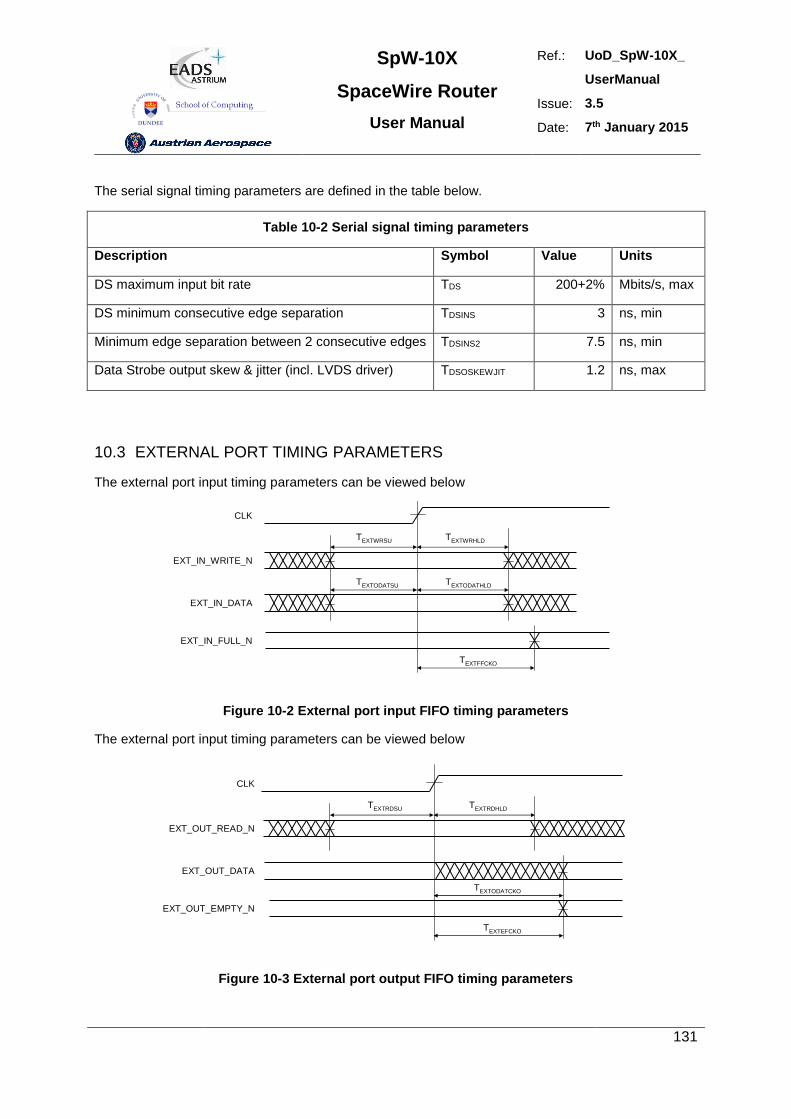
SpW-10X
SpaceWire Router
User Manual
Ref.: UoD_SpW-10X_
UserManual
Issue: 3.5
Date: 7th January 2015
131
The serial signal timing parameters are defined in the table below.
Table 10-2 Serial signal timing parameters
Description Symbol Value Units
DS maximum input bit rate TDS 200+2% Mbits/s, max
DS minimum consecutive edge separation TDSINS 3 ns, min
Minimum edge separation between 2 consecutive edges TDSINS2 7.5 ns, min
Data Strobe output skew & jitter (incl. LVDS driver) TDSOSKEWJIT 1.2 ns, max
10.3 EXTERNAL PORT TIMING PARAMETERS
The external port input timing parameters can be viewed below
CLK
EXT_IN_WRITE_N
EXT_IN_DATA
EXT_IN_FULL_N
TEXTFFCKO
TEXTODATSU TEXTODATHLD
TEXTWRSU TEXTWRHLD
Figure 10-2 External port input FIFO timing parameters
The external port input timing parameters can be viewed below
CLK
EXT_OUT_READ_N
EXT_OUT_DATA
EXT_OUT_EMPTY_N
TEXTEFCKO
TEXTRDSU TEXTRDHLD
TEXTODATCKO
Figure 10-3 External port output FIFO timing parameters
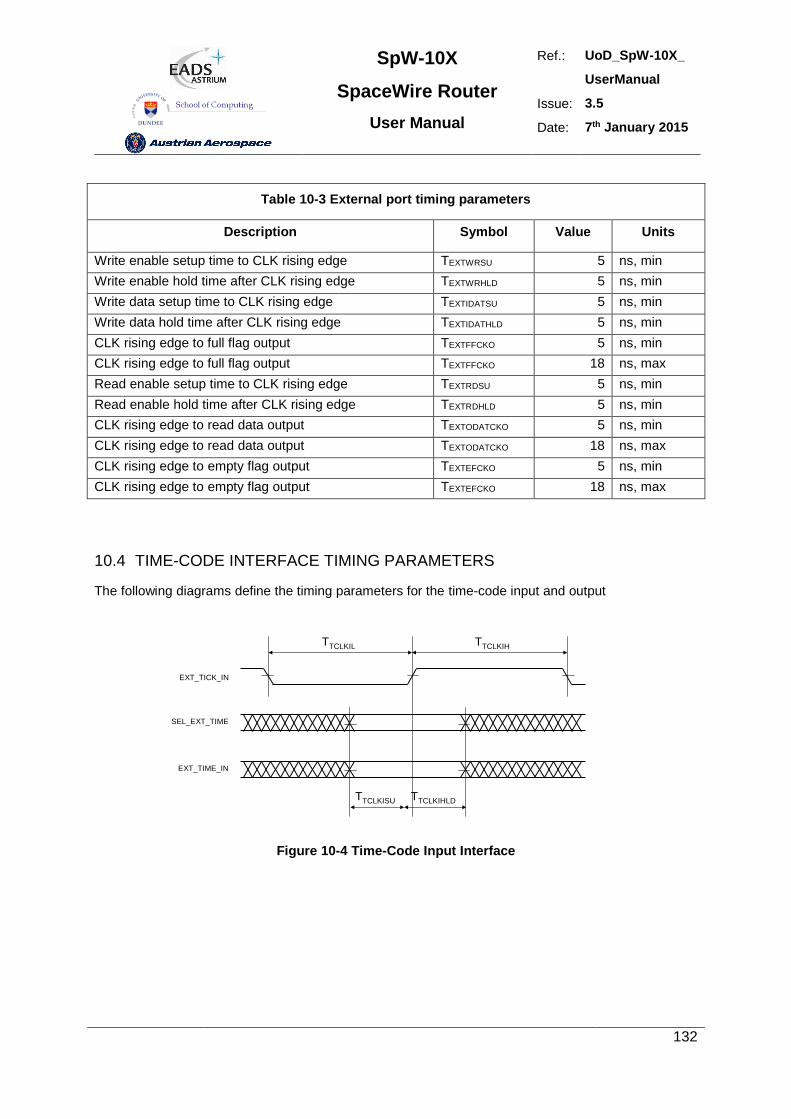
SpW-10X
SpaceWire Router
User Manual
Ref.: UoD_SpW-10X_
UserManual
Issue: 3.5
Date: 7th January 2015
132
Table 10-3 External port timing parameters
Description Symbol Value Units
Write enable setup time to CLK rising edge TEXTWRSU 5 ns, min
Write enable hold time after CLK rising edge TEXTWRHLD 5 ns, min
Write data setup time to CLK rising edge TEXTIDATSU 5 ns, min
Write data hold time after CLK rising edge TEXTIDATHLD 5 ns, min
CLK rising edge to full flag output TEXTFFCKO 5 ns, min
CLK rising edge to full flag output TEXTFFCKO 18 ns, max
Read enable setup time to CLK rising edge TEXTRDSU 5 ns, min
Read enable hold time after CLK rising edge TEXTRDHLD 5 ns, min
CLK rising edge to read data output TEXTODATCKO 5 ns, min
CLK rising edge to read data output TEXTODATCKO 18 ns, max
CLK rising edge to empty flag output TEXTEFCKO 5 ns, min
CLK rising edge to empty flag output TEXTEFCKO 18 ns, max
10.4 TIME-CODE INTERFACE TIMING PARAMETERS
The following diagrams define the timing parameters for the time-code input and output
EXT_TICK_IN
SEL_EXT_TIME
EXT_TIME_IN
TTCLKIL TTCLKIH
TTCLKISU TTCLKIHLD
Figure 10-4 Time-Code Input Interface
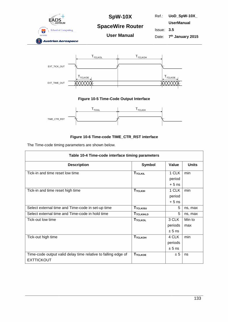
SpW-10X
SpaceWire Router
User Manual
Ref.: UoD_SpW-10X_
UserManual
Issue: 3.5
Date: 7th January 2015
133
EXT_TICK_OUT
TTCLKOL TTCLKOH
EXT_TIME_OUT
TTCLKOE TTCLKOE
Figure 10-5 Time-Code Output Interface
TIME_CTR_RST
TTCKIL TTCLKIH
Figure 10-6 Time-code TIME_CTR_RST interface
The Time-code timing parameters are shown below.
Table 10-4 Time-code interface timing parameters
Description Symbol Value Units
Tick-in and time reset low time TTCLKIL 1 CLK
period
+ 5 ns
min
Tick-in and time reset high time TTCLKIH 1 CLK
period
+ 5 ns
min
Select external time and Time-code in set-up time TTCLKISU 5 ns, max
Select external time and Time-code in hold time TTCLKIHLD 5 ns, max
Tick-out low time TTCLKOL 3 CLK
periods
± 5 ns
Min to
max
Tick-out high time TTCLKOH 4 CLK
periods
± 5 ns
min
Time-code output valid delay time relative to falling edge of
EXTTICKOUT
TTCLKOE ± 5 ns
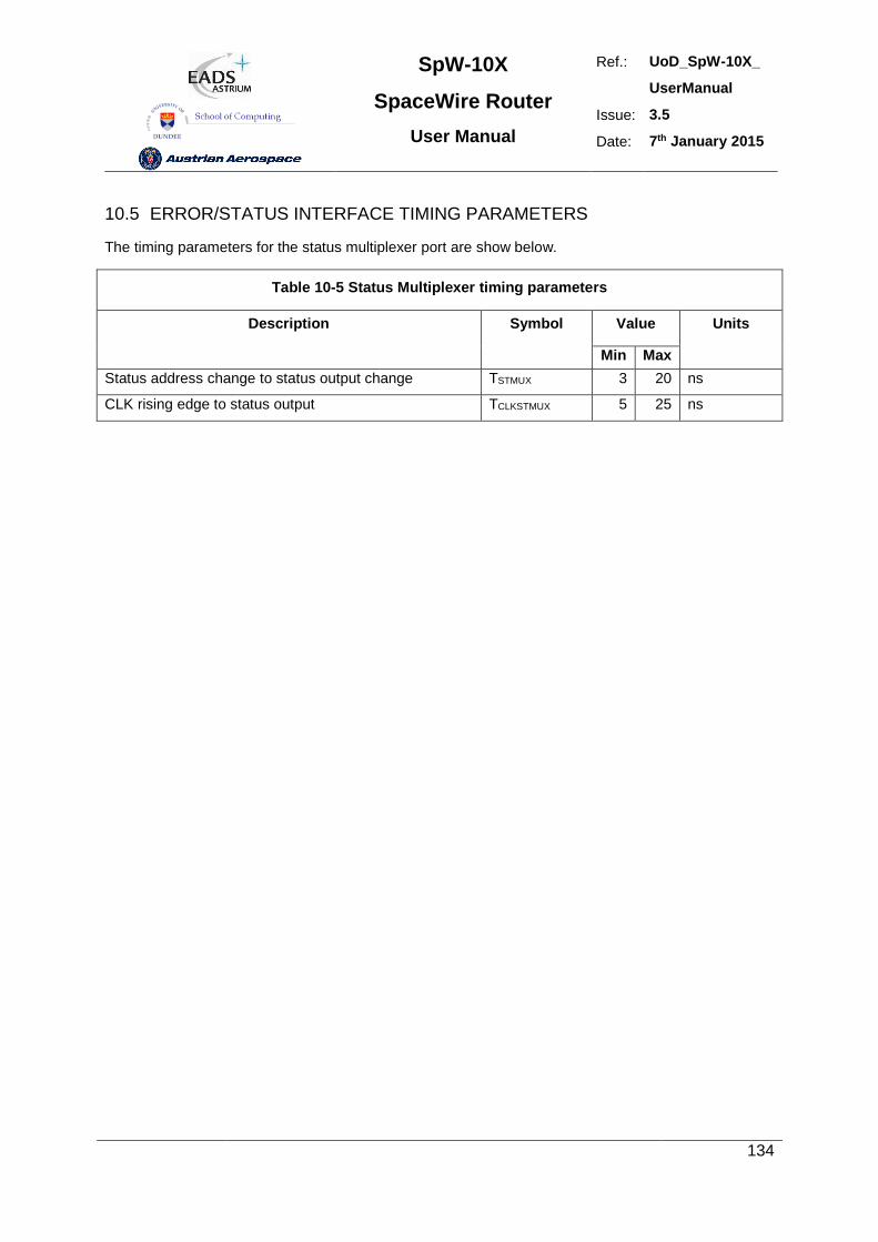
SpW-10X
SpaceWire Router
User Manual
Ref.: UoD_SpW-10X_
UserManual
Issue: 3.5
Date: 7th January 2015
134
10.5 ERROR/STATUS INTERFACE TIMING PARAMETERS
The timing parameters for the status multiplexer port are show below.
Table 10-5 Status Multiplexer timing parameters
Description Symbol Value Units
Min Max
Status address change to status output change TSTMUX 3 20 ns
CLK rising edge to status output TCLKSTMUX 5 25 ns
SpW-10X
SpaceWire Router
User Manual
Ref.: UoD_SpW-10X_
UserManual
Issue: 3.5
Date: 7th January 2015
135
10.6 LATENCY AND JITTER
The timing parameters for the data and time-code latency and the time-code jitter are derived from the
receive clock, transmit clock and system clock period. The worst case number of clock cycles required
is used in each equation.
In the SpaceWire router the system clock is a known frequency and the transmitter and receiver
frequency are derived from the input and output bit rates. The clock frequencies are defined as
follows.
Note: All figures are worst case. Due to the uncertainty of synchronisation between clock domains the
measured time may be less than indicated.
In the following sections the clock periods are defined and the latency and jitter timing parameter
definitions are detailed.
10.6.1 Clock Periods
System Clock Period
TSYSPERIOD = 33.333 ns (Clock Frequency = 30 MHz)
Transmit Clock Period
TTXPERIOD = Transmit bit rate period * 2 (Where Transmit bit rate period is the output bit rate selected
by the user configuration)
Receive Clock Period
TRXPERIOD = Receive bit rate period * 2 (Where Receive bit rate period is the period of the input bit rate)
10.6.2 Switching Latency
Switching latency is the time it takes the router to connect a waiting input port to an output port that
has just finished sending a packet. It includes any time for group adaptive routing and arbitration of
two or more input ports competing for the same output port.
Switching latency for the router is defined as follows
SYSPERIODSWITCH TT 4
10.6.3 Router Latency
Router latency is the time taken for a character in a packet to pass through the router assuming that
the packet has already been switched to an output port and that there is no blocking of the output port.
Router latency for the SpaceWire router is defined for port to port data transfer operations as follows:
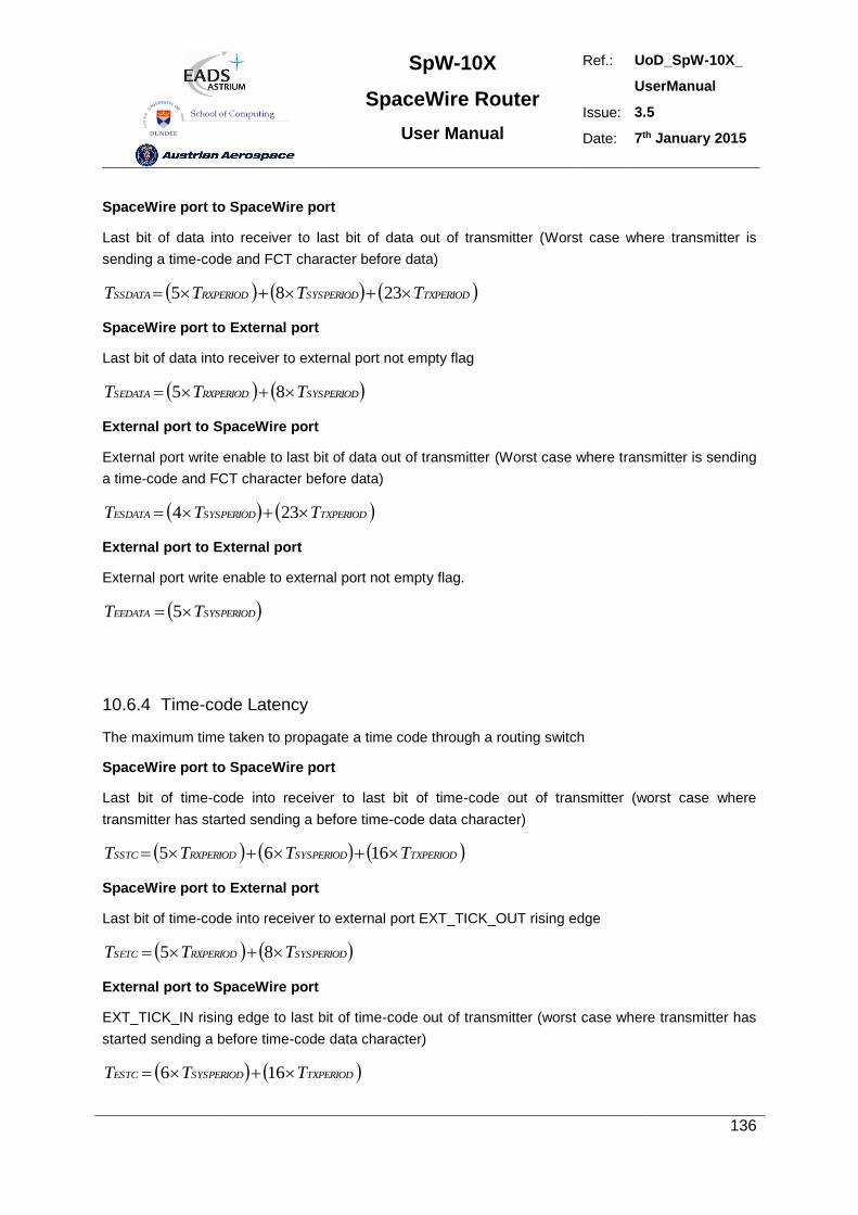
SpW-10X
SpaceWire Router
User Manual
Ref.: UoD_SpW-10X_
UserManual
Issue: 3.5
Date: 7th January 2015
136
SpaceWire port to SpaceWire port
Last bit of data into receiver to last bit of data out of transmitter (Worst case where transmitter is
sending a time-code and FCT character before data)
TXPERIODSYSPERIODRXPERIODSSDATA TTTT 2385
SpaceWire port to External port
Last bit of data into receiver to external port not empty flag
SYSPERIODRXPERIODSEDATA TTT 85
External port to SpaceWire port
External port write enable to last bit of data out of transmitter (Worst case where transmitter is sending
a time-code and FCT character before data)
TXPERIODSYSPERIODESDATA TTT 234
External port to External port
External port write enable to external port not empty flag.
SYSPERIODEEDATA TT 5
10.6.4 Time-code Latency
The maximum time taken to propagate a time code through a routing switch
SpaceWire port to SpaceWire port
Last bit of time-code into receiver to last bit of time-code out of transmitter (worst case where
transmitter has started sending a before time-code data character)
TXPERIODSYSPERIODRXPERIODSSTC TTTT 1665
SpaceWire port to External port
Last bit of time-code into receiver to external port EXT_TICK_OUT rising edge
SYSPERIODRXPERIODSETC TTT 85
External port to SpaceWire port
EXT_TICK_IN rising edge to last bit of time-code out of transmitter (worst case where transmitter has
started sending a before time-code data character)
TXPERIODSYSPERIODESTC TTT 166
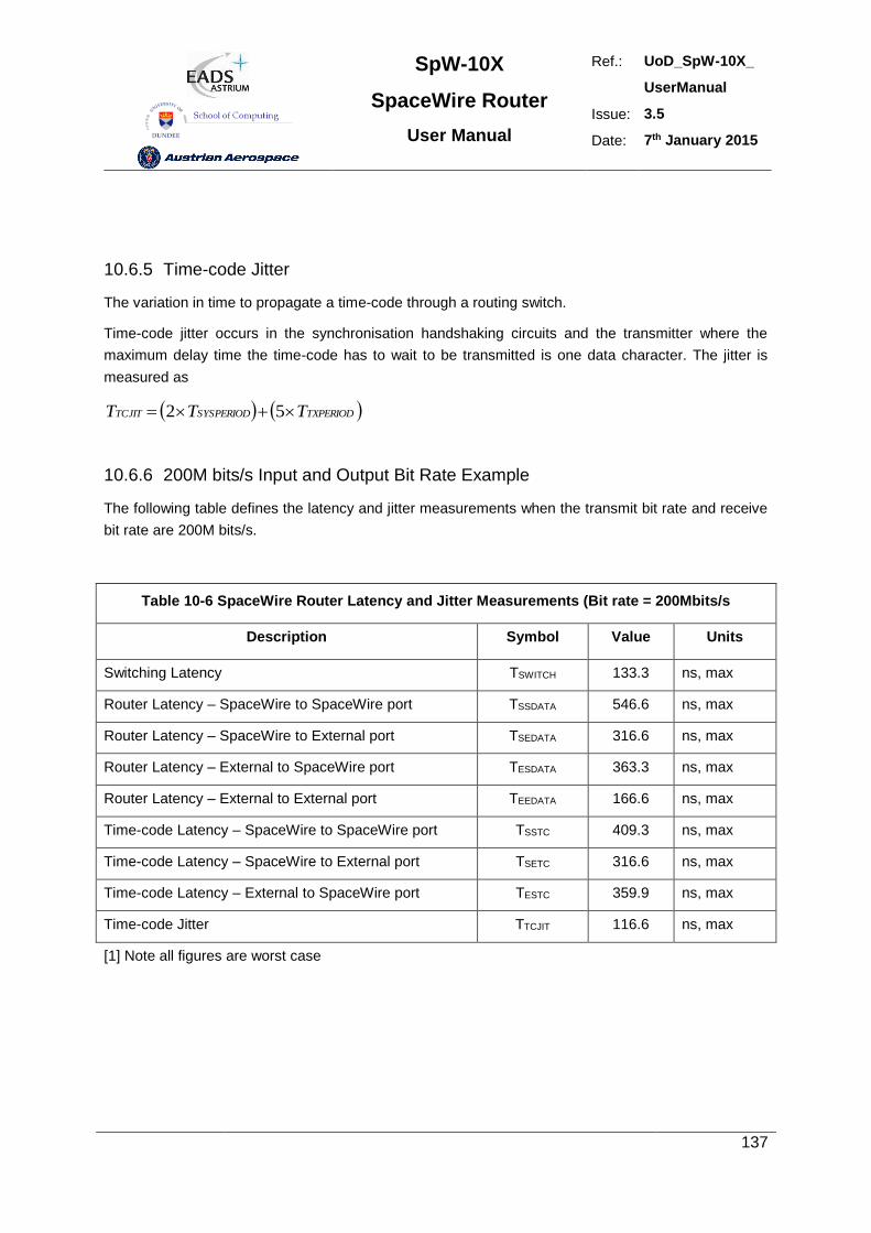
SpW-10X
SpaceWire Router
User Manual
Ref.: UoD_SpW-10X_
UserManual
Issue: 3.5
Date: 7th January 2015
137
10.6.5 Time-code Jitter
The variation in time to propagate a time-code through a routing switch.
Time-code jitter occurs in the synchronisation handshaking circuits and the transmitter where the
maximum delay time the time-code has to wait to be transmitted is one data character. The jitter is
measured as
TXPERIODSYSPERIODTCJIT TTT 52
10.6.6 200M bits/s Input and Output Bit Rate Example
The following table defines the latency and jitter measurements when the transmit bit rate and receive
bit rate are 200M bits/s.
Table 10-6 SpaceWire Router Latency and Jitter Measurements (Bit rate = 200Mbits/s
Description Symbol Value Units
Switching Latency TSWITCH 133.3 ns, max
Router Latency – SpaceWire to SpaceWire port TSSDATA 546.6 ns, max
Router Latency – SpaceWire to External port TSEDATA 316.6 ns, max
Router Latency – External to SpaceWire port TESDATA 363.3 ns, max
Router Latency – External to External port TEEDATA 166.6 ns, max
Time-code Latency – SpaceWire to SpaceWire port TSSTC 409.3 ns, max
Time-code Latency – SpaceWire to External port TSETC 316.6 ns, max
Time-code Latency – External to SpaceWire port TESTC 359.9 ns, max
Time-code Jitter TTCJIT 116.6 ns, max
[1] Note all figures are worst case
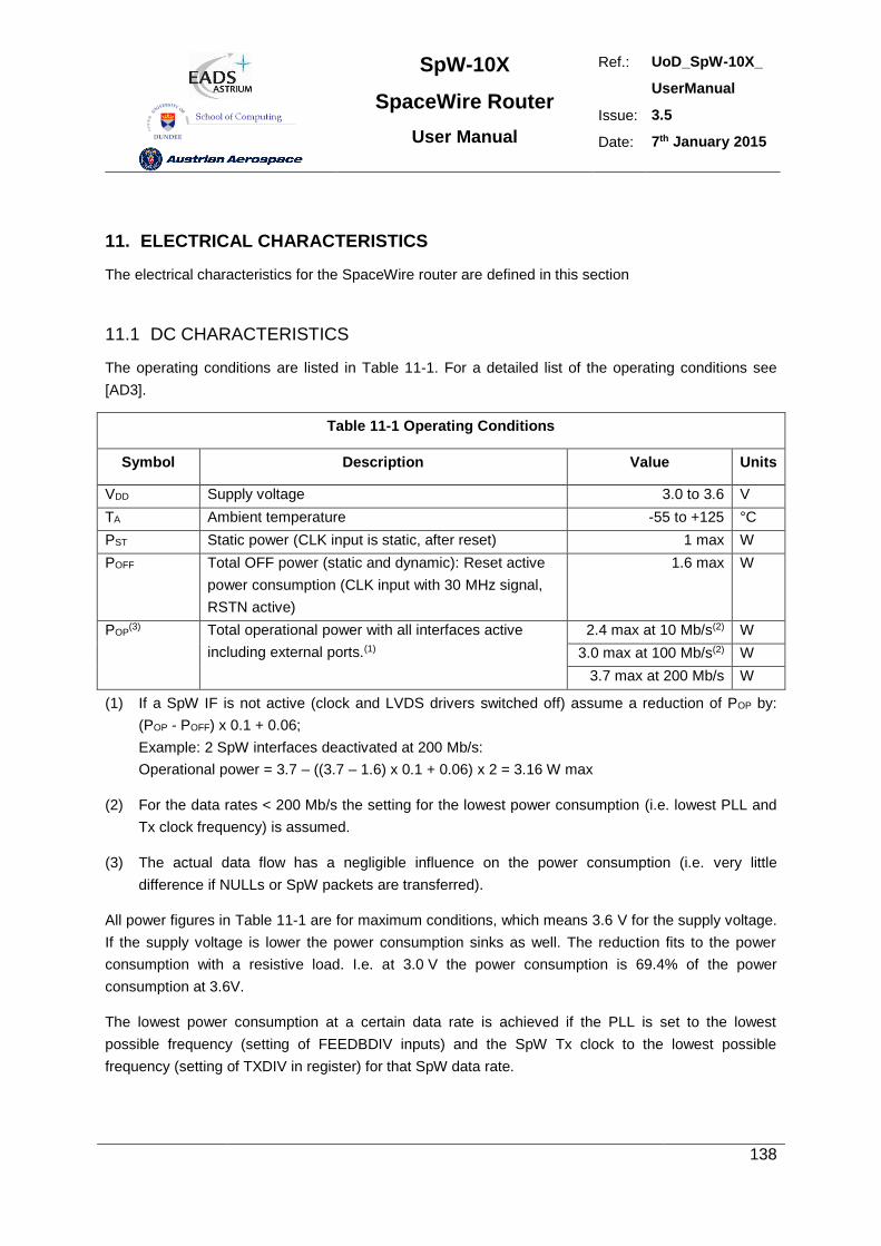
SpW-10X
SpaceWire Router
User Manual
Ref.: UoD_SpW-10X_
UserManual
Issue: 3.5
Date: 7th January 2015
138
11. ELECTRICAL CHARACTERISTICS
The electrical characteristics for the SpaceWire router are defined in this section
11.1 DC CHARACTERISTICS
The operating conditions are listed in Table 11-1. For a detailed list of the operating conditions see
[AD3].
Table 11-1 Operating Conditions
Symbol Description Value Units
VDD Supply voltage 3.0 to 3.6 V
TA Ambient temperature -55 to +125 °C
PST Static power (CLK input is static, after reset) 1 max W
POFF Total OFF power (static and dynamic): Reset active
power consumption (CLK input with 30 MHz signal,
RSTN active)
1.6 max W
POP(3) Total operational power with all interfaces active
including external ports.(1)
2.4 max at 10 Mb/s(2) W
3.0 max at 100 Mb/s(2) W
3.7 max at 200 Mb/s W
(1) If a SpW IF is not active (clock and LVDS drivers switched off) assume a reduction of POP by:
(POP - POFF) x 0.1 + 0.06;
Example: 2 SpW interfaces deactivated at 200 Mb/s:
Operational power = 3.7 – ((3.7 – 1.6) x 0.1 + 0.06) x 2 = 3.16 W max
(2) For the data rates < 200 Mb/s the setting for the lowest power consumption (i.e. lowest PLL and
Tx clock frequency) is assumed.
(3) The actual data flow has a negligible influence on the power consumption (i.e. very little
difference if NULLs or SpW packets are transferred).
All power figures in Table 11-1 are for maximum conditions, which means 3.6 V for the supply voltage.
If the supply voltage is lower the power consumption sinks as well. The reduction fits to the power
consumption with a resistive load. I.e. at 3.0 V the power consumption is 69.4% of the power
consumption at 3.6V.
The lowest power consumption at a certain data rate is achieved if the PLL is set to the lowest
possible frequency (setting of FEEDBDIV inputs) and the SpW Tx clock to the lowest possible
frequency (setting of TXDIV in register) for that SpW data rate.
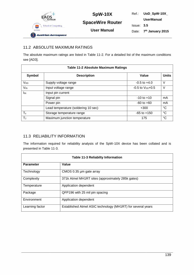
SpW-10X
SpaceWire Router
User Manual
Ref.: UoD_SpW-10X_
UserManual
Issue: 3.5
Date: 7th January 2015
139
11.2 ABSOLUTE MAXIMUM RATINGS
The absolute maximum ratings are listed in Table 11-2. For a detailed list of the maximum conditions
see [AD3].
Table 11-2 Absolute Maximum Ratings
Symbol Description Value Units
VDD Supply voltage range -0.5 to +4.0 V
VIN Input voltage range -0.5 to VDD+0.5 V
IIN Input pin current
Signal pin -10 to +10 mA
Power pin -60 to +60 mA
Lead temperature (soldering 10 sec) +300 °C
Ts Storage temperature range -65 to +150 °C
TJ Maximum junction temperature 175 °C
11.3 RELIABILITY INFORMATION
The information required for reliability analysis of the SpW-10X device has been collated and is
presented in Table 11-3.
Table 11-3 Reliabilty Information
Parameter Value
Technology CMOS 0.35 µm gate array
Complexity 371k Atmel MH1RT sites (approximately 285k gates)
Temperature Application dependent
Package QFP196 with 25 mil pin spacing
Environment Application dependent
Learning factor Established Atmel ASIC technology (MH1RT) for several years
SpW-10X
SpaceWire Router
User Manual
Ref.: UoD_SpW-10X_
UserManual
Issue: 3.5
Date: 7th January 2015
140
12. APPLICATION GUIDELINES
In this section an example circuit diagram is provided and PCB and design guidelines presented.;
12.1 EXAMPLE CIRCUIT DIAGRAM
A schematic showing how the SpW-10X device should be connected is provided on the following
page. This is a complete schematic for a stand-alone router except for the 3.3V power supply and
reset signal.
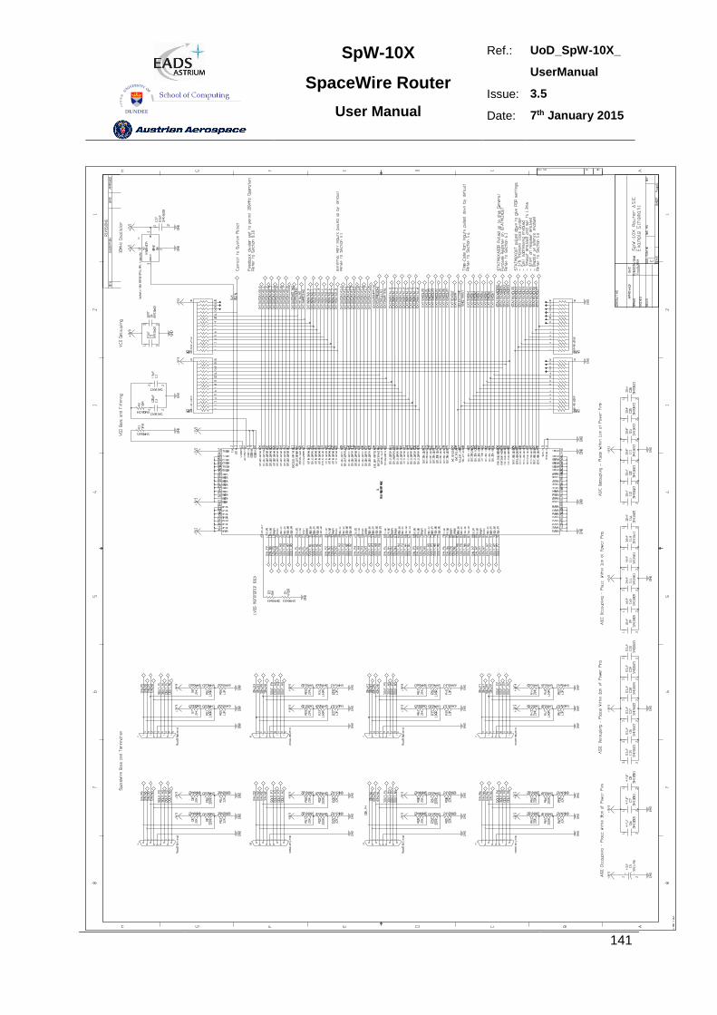
SpW-10X
SpaceWire Router
User Manual
Ref.: UoD_SpW-10X_
UserManual
Issue: 3.5
Date: 7th January 2015
141
SpW-10X
SpaceWire Router
User Manual
Ref.: UoD_SpW-10X_
UserManual
Issue: 3.5
Date: 7th January 2015
142
12.2 PCB DESIGN AND LAYOUT GUIDELINES
PCB design and layout guide lines are provided in this section.
12.2.1 CLK
1. Series termination should be used on the CLK signal.
2. Stubs on the CLK signal shall not be used.
3. Guard tracks shall be provided around the CLK signal trace connected to the ground plane
approximately every 1 cm.
12.2.2 RST_N
Guard tracks shall be provided around the RST_N signal trace connected to the ground plane
approximately every 1 cm.
12.2.3 Chip Test Signals
The two chip test signals TestIOEn and TestEn shall both be tied directly to the ground plane.
12.2.4 Power and Decoupling
1. Each power pin shall be decoupled to ground using a 100 nF decoupling capacitor.
2. The 100 nF decoupling capacitors shall be fitted close to the each power pin with the other
end of the capacitor connected to the ground plane.
3. In addition to the 100 nF decoupling capacitors four 1 µF decoupling capacitors shall be fitted
close to the SpW-10X device.
12.2.5 Ground
1. A solid ground plane shall be used.
2. The ground pins of the SpW-10X shall be directly connected to the ground plane using vias
close to the SpW-10X ground pins.
12.2.6 SpaceWire
The following recommendations apply to all the SpaceWire signals from the SpW-10X device (see
also section 5.2):
1. LVDS receiver termination resistor shall be as close as possible to the receiver inputs.
SpW-10X
SpaceWire Router
User Manual
Ref.: UoD_SpW-10X_
UserManual
Issue: 3.5
Date: 7th January 2015
143
2. LVDS fail safe resistors need not be adjacent to the termination resistor. Their location is
not critical but the stub lengths to the termination resistors should be less than 20 mm.
3. LVDS tracks shall be 100 ohm differential impedance.
4. Skew between the plus and minus sides of the LVDS differential pair shall be avoided and
shall be less than +/- 1 mm.
5. Data and strobe track lengths shall be matched to +/- 2.5 mm to keep skew to a minimum.
6. There is no need to match input and output track lengths.
7. Vias shall only be used at the SpaceWire connector and close to the SpW-10X device
(within 5 mm).
12.2.7 External Ports
The following recommendations apply to the External FIFO port signals from the SpW-10X device:
1. When the External FIFO ports are used, series termination resistors (33 ohm) should be used
on each output if the tracks on the outputs are more than 4 cm in length.
2. The series termination resistors should be placed as close as possible to the output pins of the
SpW-10X device.
3. Series termination resistors are also recommended on the devices driving the External FIFO
port inputs if the tracks connected to the inputs are more than 4 cm in length.
4. The pull up/down resistor recommendations provided in section 5.3 should be followed.
12.2.8 Time-code Interface
The following recommendations apply to the Time-code signals from the SpW-10X device:
1. When the time-code interface is used, series termination resistors (33 ohm) should be fitted to
each output if the tracks on the outputs are more than 4 cm in length.
2. The series termination resistors should be placed as close as possible to the output pins of the
SpW-10X device.
3. Series termination resistors are also recommended on the devices driving the time-code
inputs if the tracks connected to these inputs are more than 4 cm in length.
4. The pull up/down resistor recommendations provided in section 5.4 should be followed.
12.2.9 Status / Power On Configuration Interface
The pull up/down resistor recommendations provided in section 5.6 should be followed for power on
configuration.
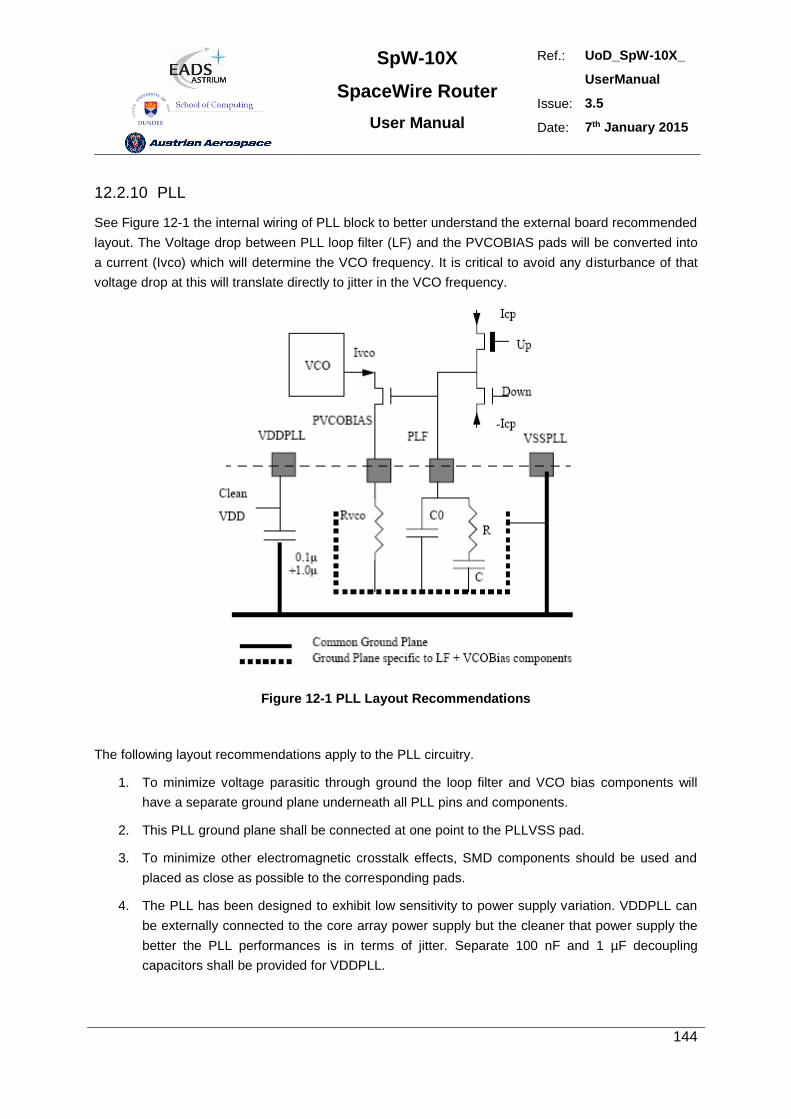
SpW-10X
SpaceWire Router
User Manual
Ref.: UoD_SpW-10X_
UserManual
Issue: 3.5
Date: 7th January 2015
144
12.2.10 PLL
See Figure 12-1 the internal wiring of PLL block to better understand the external board recommended
layout. The Voltage drop between PLL loop filter (LF) and the PVCOBIAS pads will be converted into
a current (Ivco) which will determine the VCO frequency. It is critical to avoid any disturbance of that
voltage drop at this will translate directly to jitter in the VCO frequency.
Figure 12-1 PLL Layout Recommendations
The following layout recommendations apply to the PLL circuitry.
1. To minimize voltage parasitic through ground the loop filter and VCO bias components will
have a separate ground plane underneath all PLL pins and components.
2. This PLL ground plane shall be connected at one point to the PLLVSS pad.
3. To minimize other electromagnetic crosstalk effects, SMD components should be used and
placed as close as possible to the corresponding pads.
4. The PLL has been designed to exhibit low sensitivity to power supply variation. VDDPLL can
be externally connected to the core array power supply but the cleaner that power supply the
better the PLL performances is in terms of jitter. Separate 100 nF and 1 µF decoupling
capacitors shall be provided for VDDPLL.
SpW-10X
SpaceWire Router
User Manual
Ref.: UoD_SpW-10X_
UserManual
Issue: 3.5
Date: 7th January 2015
145
13. ANOMALIES AND WARNINGS
In this section a list of anomalies and warnings is provided:
13.1 ANOMALIES
The following anomalies are present in the prototype SpW-10X router device:
1. Simultaneous transitions on data and strobe can occur during reset and power up. This may be a
problem when operating with legacy IEEE-1355 devices but is not a problem when operating with
SpaceWire compliant devices. See section 13.3for further details on this anomaly.
2. When a parity error in a data character the following characters may be received before the link
disconnects.
13.2 WARNINGS
Various warnings appear in boxes throughout this document. They are all gathered in this section for
convenience.
WARNING
Simultaneous data/strobe transitions can occur during reset and power up. This is not a problem when
connected to SpaceWire compliant devices but is a problem when connected to IEEE-1355 devices.
WARNING
Since LVDS is based on a current loop it should not matter what the supply voltage is to an LVDS
device connected to the SpW-10X router. However, there is a potential problem when connecting to
devices with power supplies greater than 3.3 V, which is the supply voltage of the SpW-10X device. It
should be emphasised that during normal operation there is no problem, but if the LVDS device
connected to the SpW-10X device can fail in such a way as to put a higher voltage than 3.3 V on to
the pins of the SpW-10X device then this can cause a problem. The simplest way to overcome this
potential problem is to ensure that the LVDS devices driving the SpW-10X device are all powered by
3.3V.
SpW-10X
SpaceWire Router
User Manual
Ref.: UoD_SpW-10X_
UserManual
Issue: 3.5
Date: 7th January 2015
146
WARNING
The deactivate mode (see also section 9.4.3) does not tri-state the LVDS outputs. The LVDS outputs
are cold-sparing and when disabled both outputs in an LVDS differential pair are pulled up to 3.3V and
have an impedance of the order of 1 kohm. Since they are differential outputs and are both are at the
same voltage no current will flow. If, however, external noise bias resistors are being used then a
small current (around 200 µA, 0.7 mW power) can flow. This is substantially less than the normal
operating current of LVDS outputs and hence saves power.
WARNING
In most onboard applications it is recommended to have Stat_mux_out(4) pulled low by default in
order to enable the watchdog timers on reset.
WARNING
When the watchdog timers are not enabled the SpaceWire and external ports can block indefinitely if,
for example, a source stops sending data in the middle of a packet. If watchdog timers are not enabled
then it must be possible for a network manager to detect blocking situations and to reset the router or
node creating the problem.
WARNING
If the link that is being used to configure the router is disabled then it will not be possible to configure
the router, unless there is another not disabled connection that can be used.
WARNING
Blocking Allowed mode is not recommended and should be used with caution.
When Blocking Allowed mode is used (Watchdog timers disabled) then it is important that provision is
made for a network manager to detect blocking situations and to reset the nodes or routers causing
the problem.
SpW-10X
SpaceWire Router
User Manual
Ref.: UoD_SpW-10X_
UserManual
Issue: 3.5
Date: 7th January 2015
147
WARNING
Packets can timeout and be spilled in a SpaceWire network without the destination receiving any
notification of this. Packets with errors (e.g. parity error) can arrive at a destination terminated by an
EEP. In a very special case it is also possible to receive an error free packet terminated by an EEP. It
is important that the destination node is able to handle these cases.
WARNING
Care must be taken when setting a the routing tables to avoid a possible infinite loop. For example if
there is a SpaceWire link made between two ports of a single router and a logical address routes a
packet out of one of these ports then that packet will arrive back at the router, and be routed back out
of the port again. Depending on the size of the packet it may block because it cannot get access to the
output port the second time around as the tail of the packet is still being fed to the output port. In this
case the blockage will cause a timeout (when watchdog timer mode set – see section 8.3.5) and the
packet will be spilt. If the packet is a small packet it could continually circle around the loop. A
SpaceWire network architecture and configuration should be checked for possible loops for all logical
addresses being used. Unused logical addresses should NOT be configured in the SpW-10X routing
tables so that a packet arriving at a router with an invalid (unused) logical address will be spilt
immediately.
WARNING
If a SpaceWire port that is being used to configure a router has its transmit clock turned off then it will
not be possible to configure the router using that port. Unless there is another connection with an
active clock and which is not disabled that can be used to perform configuration the router will have to
be reset before it can be configured again.
13.3 RESET ANOMALY
This section describes the reset anomaly and suggests appropriate workarounds.
13.3.1 Data Strobe Reset Waveform
If a SpaceWire link is running when the SpW-10X device is reset, part of a NULL pattern is present on
the serial data/strobe outputs of the running link when reset is released, see Figure 13-1. Data and
strobe outputs hold their previous values until reset is applied as seen in Figure 13-2. When reset is
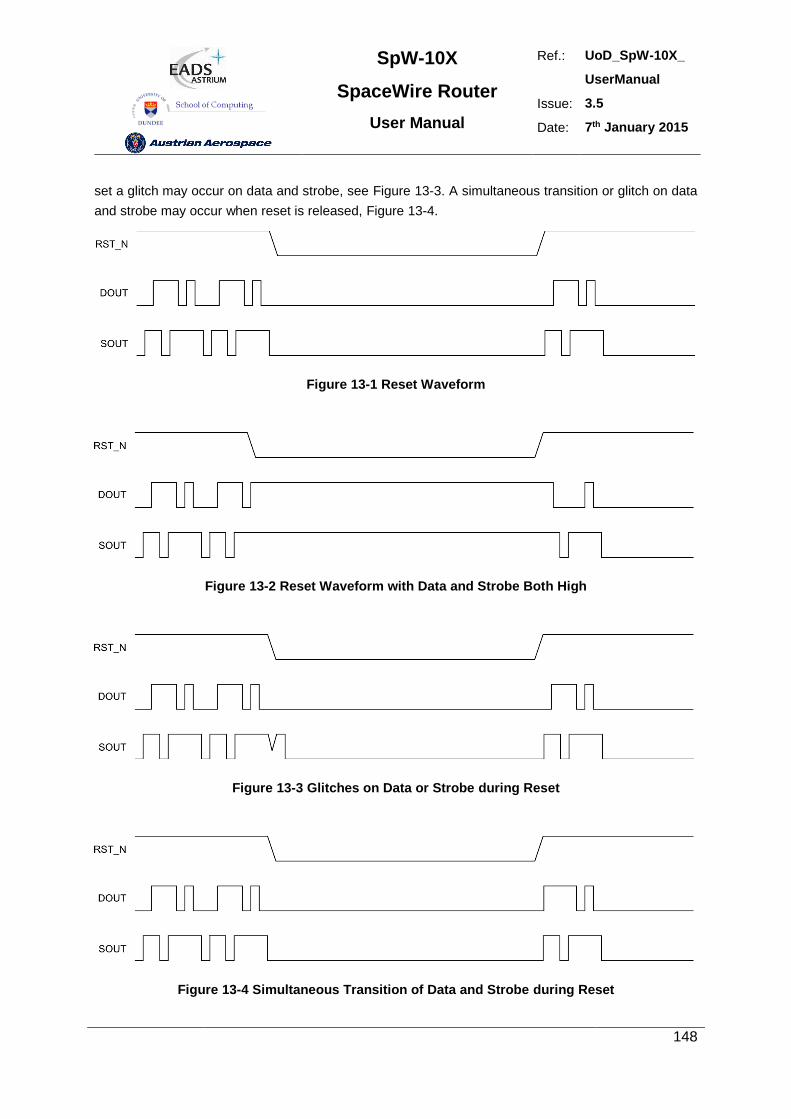
SpW-10X
SpaceWire Router
User Manual
Ref.: UoD_SpW-10X_
UserManual
Issue: 3.5
Date: 7th January 2015
148
set a glitch may occur on data and strobe, see Figure 13-3. A simultaneous transition or glitch on data
and strobe may occur when reset is released, Figure 13-4.
Figure 13-1 Reset Waveform
Figure 13-2 Reset Waveform with Data and Strobe Both High
Figure 13-3 Glitches on Data or Strobe during Reset
Figure 13-4 Simultaneous Transition of Data and Strobe during Reset
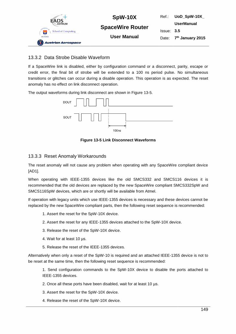
SpW-10X
SpaceWire Router
User Manual
Ref.: UoD_SpW-10X_
UserManual
Issue: 3.5
Date: 7th January 2015
149
13.3.2 Data Strobe Disable Waveform
If a SpaceWire link is disabled, either by configuration command or a disconnect, parity, escape or
credit error, the final bit of strobe will be extended to a 100 ns period pulse. No simultaneous
transitions or glitches can occur during a disable operation. This operation is as expected. The reset
anomaly has no effect on link disconnect operation.
The output waveforms during link disconnect are shown in Figure 13-5.
Figure 13-5 Link Disconnect Waveforms
13.3.3 Reset Anomaly Workarounds
The reset anomaly will not cause any problem when operating with any SpaceWire compliant device
[AD1].
When operating with IEEE-1355 devices like the old SMCS332 and SMCS116 devices it is
recommended that the old devices are replaced by the new SpaceWire compliant SMCS332SpW and
SMCS116SpW devices, which are or shortly will be available from Atmel.
If operation with legacy units which use IEEE-1355 devices is necessary and these devices cannot be
replaced by the new SpaceWire compliant parts, then the following reset sequence is recommended:
1. Assert the reset for the SpW-10X device.
2. Assert the reset for any IEEE-1355 devices attached to the SpW-10X device.
3. Release the reset of the SpW-10X device.
4. Wait for at least 10 µs.
5. Release the reset of the IEEE-1355 devices.
Alternatively when only a reset of the SpW-10 is required and an attached IEEE-1355 device is not to
be reset at the same time, then the following reset sequence is recommended:
1. Send configuration commands to the SpW-10X device to disable the ports attached to
IEEE-1355 devices.
2. Once all these ports have been disabled, wait for at least 10 µs.
3. Assert the reset for the SpW-10X device.
4. Release the reset of the SpW-10X device.
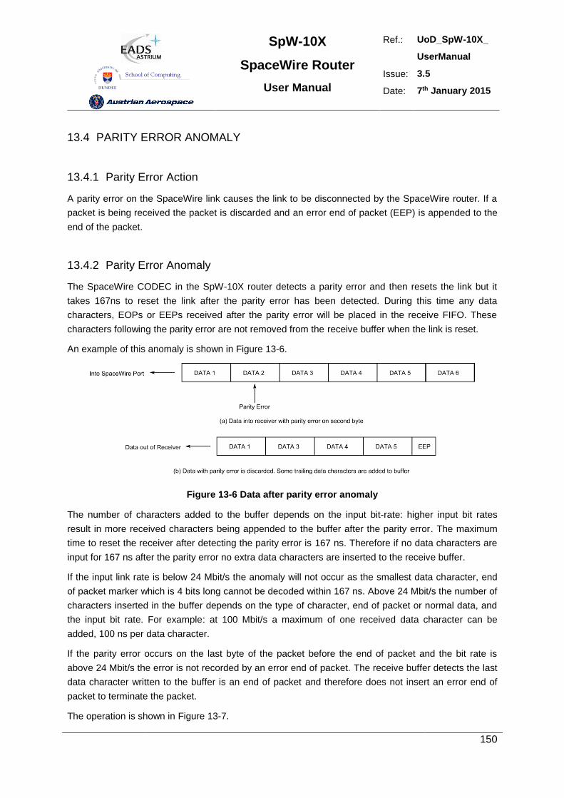
SpW-10X
SpaceWire Router
User Manual
Ref.: UoD_SpW-10X_
UserManual
Issue: 3.5
Date: 7th January 2015
150
13.4 PARITY ERROR ANOMALY
13.4.1 Parity Error Action
A parity error on the SpaceWire link causes the link to be disconnected by the SpaceWire router. If a
packet is being received the packet is discarded and an error end of packet (EEP) is appended to the
end of the packet.
13.4.2 Parity Error Anomaly
The SpaceWire CODEC in the SpW-10X router detects a parity error and then resets the link but it
takes 167ns to reset the link after the parity error has been detected. During this time any data
characters, EOPs or EEPs received after the parity error will be placed in the receive FIFO. These
characters following the parity error are not removed from the receive buffer when the link is reset.
An example of this anomaly is shown in Figure 13-6.
Figure 13-6 Data after parity error anomaly
The number of characters added to the buffer depends on the input bit-rate: higher input bit rates
result in more received characters being appended to the buffer after the parity error. The maximum
time to reset the receiver after detecting the parity error is 167 ns. Therefore if no data characters are
input for 167 ns after the parity error no extra data characters are inserted to the receive buffer.
If the input link rate is below 24 Mbit/s the anomaly will not occur as the smallest data character, end
of packet marker which is 4 bits long cannot be decoded within 167 ns. Above 24 Mbit/s the number of
characters inserted in the buffer depends on the type of character, end of packet or normal data, and
the input bit rate. For example: at 100 Mbit/s a maximum of one received data character can be
added, 100 ns per data character.
If the parity error occurs on the last byte of the packet before the end of packet and the bit rate is
above 24 Mbit/s the error is not recorded by an error end of packet. The receive buffer detects the last
data character written to the buffer is an end of packet and therefore does not insert an error end of
packet to terminate the packet.
The operation is shown in Figure 13-7.
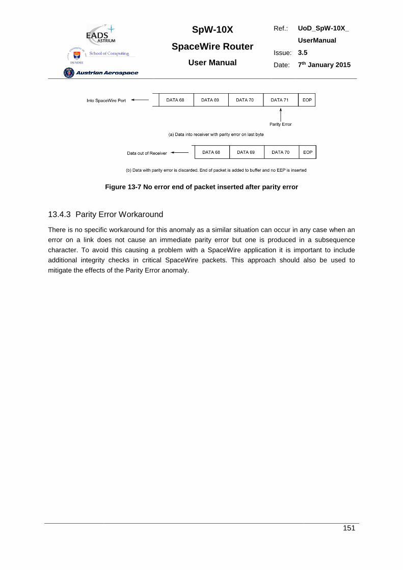
SpW-10X
SpaceWire Router
User Manual
Ref.: UoD_SpW-10X_
UserManual
Issue: 3.5
Date: 7th January 2015
151
Figure 13-7 No error end of packet inserted after parity error
13.4.3 Parity Error Workaround
There is no specific workaround for this anomaly as a similar situation can occur in any case when an
error on a link does not cause an immediate parity error but one is produced in a subsequence
character. To avoid this causing a problem with a SpaceWire application it is important to include
additional integrity checks in critical SpaceWire packets. This approach should also be used to
mitigate the effects of the Parity Error anomaly.
SpW-10X
SpaceWire Router
User Manual
Ref.: UoD_SpW-10X_
UserManual
Issue: 3.5
Date: 7th January 2015
152
14. TECHNICAL SUPPORT
Technical support for the SpW-10X Router is provided by STAR-Dundee Ltd. A range of SpW-10X
evaluation boards is available along with other test equipment, cables etc. See www.star-dundee.com
for details.
Technical support is provided by STAR-Dundee. All requests for support should be submitted to the
Atmel support hotline:
Email: [email protected]
SpW-10X
SpaceWire Router
User Manual
Ref.: UoD_SpW-10X_
UserManual
Issue: 3.5
Date: 7th January 2015
153
15. DOCUMENT CHANGES
15.1 ISSUE 3.4 TO ISSUE 3.5
Section Ref Change
5 Table 5-2 SOUTMinus(4) pin location is pin 52 as indicated in section 4.
9 Table 9-10 Correction to the POR_SEL_TIMEOUT_N pin polarity when
reset is applied. 0 maps to 1.3 milliseconds and 1 maps to 60-
100 microseconds.
10 Table 10-1 TBC notes removed from clock and reset timing parameters.
Preliminary notice removed from footer.
15.2 ISSUE 3.3 TO ISSUE 3.4
Section Ref Change
13.1
13.4
Parity error anomaly added to the list of anomalies.
Details of parity error anomaly added.
6.4
10.1
10.2
10.3
10.4
10.5
11.1
Update after characterisation tests of the SpW-10X prototypes:
Corrected STATMUXOUT input valid time after reset
Clock and Reset switching characteristics added
DS skew parameter changed to total Tx skew & jitter
External port timing added
Time code interface timing completed / corrected
Error / Status interface timing added
Power consumption parameters updated
15.3 ISSUE 3.2 TO ISSUE 3.3
Section Ref Change
1.2 Table 1-2 RD3 changed to more appropriate reference document that
includes information on LVDS.
8.1.5 Figure 8-3 Bias resistor value corrected to 20k ohms.
9.3 Table 9-3 The reset values of the GAR bits are undefined after power on
and unchanged after reset except the Invalid Address bit which
is 1 after power on or reset.
12.2.6 Point 1 Editorial change to text.
SpW-10X
SpaceWire Router
User Manual
Ref.: UoD_SpW-10X_
UserManual
Issue: 3.5
Date: 7th January 2015
154
12.2.6 Point 5 Editorial change to text.
14 Correction made to support email address.
15.4 ISSUE 3.1 TO ISSUE 3.2
Section Ref Change
1.2 Table 1-2 RD3 added “Atmel MH1RT Cold Sparing I/O Buffers”.
3 Figure 3.1 Text in diagram change from “non-blocking crossbar switch” to
“crossbar switch”.
3.5 Explanation of “non-blocking” nature of crossbar switch added.
5.1.2 Sentence added explaining that LVDS inputs and output are
cold sparing and giving reference to RD3.
5.7.4 VCO bias resistor value corrected (Section 5.7.4).
8.1.5 Tri-state mode changed to deactivate mode. Calculation of
deactivated power consumption added.
9.4.3 Table 9-6 Tri-state mode changed to deactivated mode.
9.5.8 Description for ‘time-code flag mode bit’ added.
11.1 Table 11-1 Power information updated.
11.3 Section added on reliability information
13.1 Reference to further details on anomaly 1 in section 13.3
added.
Anomaly 2 (tri-state mode) removed. The text throughout the
document related to tri-state mode has been corrected to
deactivated mode. A warning that the deactivated mode is not
true tri-state has been added.
13.3 Section added to give more details on reset anomaly.
15.5 ISSUE 3.0 TO ISSUE 3.1
Section Ref Change
5.6 Second warning clarified.
7.6.10 Note added explaining that command packet fill bytes is a
feature of the SpW-10X and not of RMAP.
8.1.6
13.2
Warning on setting data rate to less than 2 Mbits/s deleted.
The SpW-10X device will not allow a TXDIV and TXRATE to be
set to give a transmit data rate below 2 Mbits/s.
8.3.2.4 Note added to further explain blocking of low priority packets by
high priority ones.
8.3.5.3 Corrections made. When output port not running or in a group
and not running, the router will waits for the timeout period for
SpW-10X
SpaceWire Router
User Manual
Ref.: UoD_SpW-10X_
UserManual
Issue: 3.5
Date: 7th January 2015
155
the link to start. If it does not start in that time then the packet
will be spilt.
11.1 References to [AD3] corrected.
12.1 Example schematic changed to a format that is readable.
15.6 ISSUE 2.5 TO ISSUE 3.0
Section Ref Change
Entire
document
Major edit providing clarifications and additional application
details throughout document.
Section added on Application Guidelines giving example circuit
diagram and PCB layout guidelines.
Section added on anomalies and warnings.
Section added on Technical Support.
15.7 ISSUE 2.4 TO ISSUE 2.5
Section Ref Change
Update document revision and redistribute
11.1 Change VCC to VDD.
11.2 Remove VCC
15.8 ISSUE 2.3 TO ISSUE 2.4
Section Ref Change
Title Change from data sheet to user manual
Title Add Atmel part number as a reference
3.2 External Ports Add depth of external port FIFOs.
5.2 SpaceWire
Signals
Rename data strobe IOs so the naming is consistent in the
document. Note pin names should map to pin names in the
data-sheet therefore use Plus/Minus notation
5.7 Power,
Ground, PLL
and LVDS
Signals
Additional information on power pins and PLL power supply
circuitry.
10.3 Group Adaptive Add mapping of SpaceWire Ports 1 to 8 and External ports 9
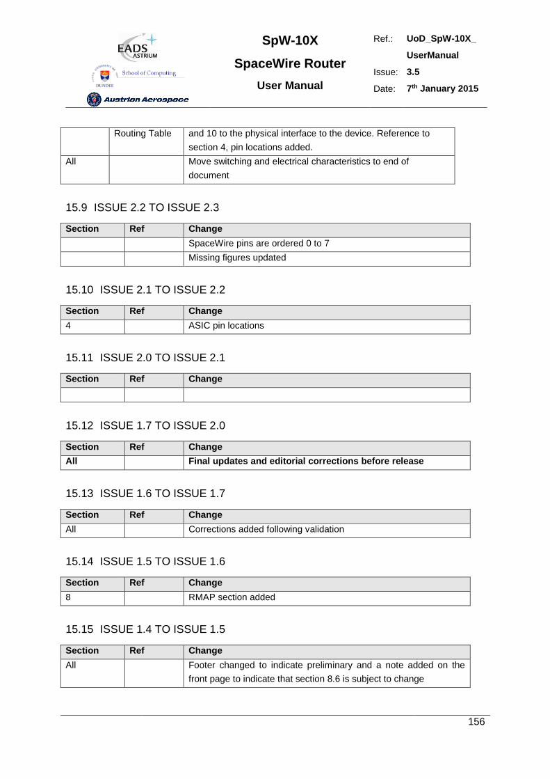
SpW-10X
SpaceWire Router
User Manual
Ref.: UoD_SpW-10X_
UserManual
Issue: 3.5
Date: 7th January 2015
156
Routing Table and 10 to the physical interface to the device. Reference to
section 4, pin locations added.
All Move switching and electrical characteristics to end of
document
15.9 ISSUE 2.2 TO ISSUE 2.3
Section Ref Change
SpaceWire pins are ordered 0 to 7
Missing figures updated
15.10 ISSUE 2.1 TO ISSUE 2.2
Section Ref Change
4 ASIC pin locations
15.11 ISSUE 2.0 TO ISSUE 2.1
Section Ref Change
15.12 ISSUE 1.7 TO ISSUE 2.0
Section Ref Change
All Final updates and editorial corrections before release
15.13 ISSUE 1.6 TO ISSUE 1.7
Section Ref Change
All Corrections added following validation
15.14 ISSUE 1.5 TO ISSUE 1.6
Section Ref Change
8 RMAP section added
15.15 ISSUE 1.4 TO ISSUE 1.5
Section Ref Change
All Footer changed to indicate preliminary and a note added on the
front page to indicate that section 8.6 is subject to change
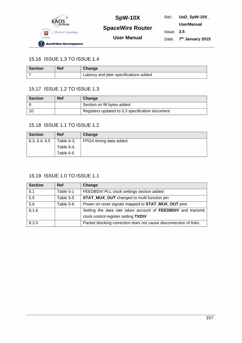
SpW-10X
SpaceWire Router
User Manual
Ref.: UoD_SpW-10X_
UserManual
Issue: 3.5
Date: 7th January 2015
157
15.16 ISSUE 1.3 TO ISSUE 1.4
Section Ref Change
7 Latency and jitter specifications added
15.17 ISSUE 1.2 TO ISSUE 1.3
Section Ref Change
8 Section on fill bytes added
10 Registers updated to 3.3 specification document
15.18 ISSUE 1.1 TO ISSUE 1.2
Section Ref Change
6.3, 6.4, 6.5 Table 6-3,
Table 6-4,
Table 6-5
FPGA timing data added
15.19 ISSUE 1.0 TO ISSUE 1.1
Section Ref Change
5.1 Table 5-1 FEEDBDIV PLL clock settings section added
5.5 Table 5-5 STAT_MUX_OUT changed to multi function pin
5.6 Table 5-6 Power on reset signals mapped to STAT_MUX_OUT pins
8.1.6 Setting the data rate takes account of FEEDBDIV and transmit
clock control register setting TXDIV
8.3.5 Packet blocking correction does not cause disconnection of links.