Spread Spectrum Signals for Digital Communications
29
SPREAD SPECTRUM (SS) SIGNALS FOR DIGITAL COMMUNICATIONS VERSION 1.1 Dr. Ali Muqaibel Dr. Ali Hussein Muqaibel 1
Transcript of Spread Spectrum Signals for Digital Communications

SPREAD SPECTRUM (SS)
SIGNALS FOR DIGITAL
COMMUNICATIONS
VERSION 1.1
Dr. Ali Muqaibel
Dr. Ali Hussein Muqaibel 1

Introduction
In Spread Spectrum, the bandwidth 𝑊 is much greater
than the info rate 𝑅 (bit/sec).
Bandwidth Expansion Factor 𝐵𝑒 =𝑊
𝑅≫ 1
Redundancy is introduced to overcome interference
(Radio & Satellite)
Coding is an effective method for introducing
redundancy.
Pseudo randomness signals: appear like noise and are
difficult to receive by the non-intended receivers.
Narrow band signal
(data)
Wideband signal
(transmitted SS signal)
Dr. Ali Hussein Muqaibel 2

Major Applications of SS
1. Combating/Suppressing Jamming/interference due to other users/self-interference (Multipath).
2. Covert (hidden)/Secure Communication/Privacy◦ Communication Security vs. information security
◦ Spreading sequence can be very long -> enables low transmitted PSD-> low probability of interception (LPI)(especially in military communications)
3. CDMA: Coded division Multiple Access.. QUALCOMM lie!
◦ CDMA allow multiple users to simultaneously use a common channel for transmission of information
◦ Key=code
4. In Radar SS is used for time delay, velocity, and ranging.
Dr. Ali Hussein Muqaibel 3

How Tele-operators Market CDMA
Coverage
For Coverage, CDMA saves
wireless carriers from deploying
the 400% more cell site that
are required by GSM
CDMA’s capacity supports at
least 400% more revenue-producing
subscribers in the same spectrum
when compared to GSM
Capacity Cost
$$A carrier who deploys CDMA
instead of GSM will have
a lower capital cost
Clarity
CDMA with PureVoice
provides wireline clarity
Choice
CDMA offers the choice of simultaneous
voice, async and packet data, FAX, and
SMS.
Customer satisfaction
The Most solid foundation for
attracting and retaining subscriber
is based on CDMA
*From Samsumg’s narrowband CDMA (CDMAOne®) marketing (2001)
Dr. Ali Hussein Muqaibel 4

Multiple access: FDMA, TDMA and CDMA
•FDMA, TDMA and CDMA yield
conceptually the same capacity
• However, in wireless communications
CDMA has improved capacity due to
• statistical multiplexing
• graceful degradation
•Performance can still be improved by
adaptive antennas, multiuser detection,
FEC, and multi-rate encoding
Dr. Ali Hussein Muqaibel 5

FDMA, TDMA and CDMA compared
TDMA and FDMA principle: ◦ TDMA allocates a time instant for a user
◦ FDMA allocates a frequency band for a user
◦ CDMA allocates a code for user
CDMA-system can be synchronous or asynchronous:◦ Synchronous CDMA difficult to apply in multipath channels
that destroy code orthogonality
◦ Therefore, in wireless CDMA-systems as in IS-95,cdma2000, WCDMA and IEEE 802.11 users are asynchronous
Code classification:◦ Orthogonal, as Walsh-codes for orthogonal or
near-orthogonal systems
◦ Near-orthogonal and non-orthogonal codes: Gold-codes, for asynchronous systems
Maximal length codes for asynchronous systems
Dr. Ali Hussein Muqaibel 6

Coverage Objective
Types of SS
1. Direct Sequence SS (DSSS)
PSK/QPSK+ pseudo-noise (PN) sequence
2. Frequency Hopping SS (FHSS)
M-ary FSK+PN
The pseudorandom sequence selects the frequency
of the transmitted sequence randomly
Anti-jamming (AJ) performance
Dr. Ali Hussein Muqaibel 7

Example of DS multiple access
waveforms
channel->
detecting A ... ->
polar sig.->
Dr. Ali Hussein Muqaibel 8

Frequency Hopping Spread Spectrum (FH-SS) (example: transmission of two symbols/chip)
2 levelsL
2 slotsk
:chip duration
: bit duration
: symbol duration
c
b
s
T
T
T
2 ( data modulator BW)
2 ( total FH spectral width)
L
d d
k
s d
W f
W W
bT
2L
4-level FSK modulation
Hopped frequency
slot determined by
hopping code
Dr. Ali Hussein Muqaibel 9

Model of SS Digital Comm. Sys.
The channel encoder: coding is usually employed to enhance the gain.
Synchronization (of the PN sequence)
◦ Initially, training!, transmit a fixed PM bit pattern that the receiver will
recognize in the presence of interference with high probability.
Dr. Ali Hussein Muqaibel 10

Interference & jamming
It ch/s depends on its origin (military)
1. Tone
2. Multi-tone
3. Partial band (Narrowband)
4. Broadband
5. Continuous/Pulsed (discontinuous)
6. Fixed/ time variant
1 to 4 have similar effects on DSSS
If the interference is broadband , it may be characterized as an equivalent AWGN
In CDMA we can have multi user interference.
𝑊𝑠𝑠
Tone
𝑊𝑠𝑠
Multi-Tone
𝑊𝑠𝑠
Partial band
𝑊𝑠𝑠
Broad band𝐽0
𝑇𝑝
Pulsed
𝜌𝑇𝑝
time
Dr. Ali Hussein Muqaibel 11

Objective (more details)
Performance evaluation of SS in the
presence of NB/broadband interference.
Two types of modulation are considered:
◦ PSK if phase coherence is possible for time
longer than 1
𝑊.
◦ FSK if phase coherence is not possible for
time longer than 1
𝑊. Like the time varying
channels (aircrafts)
Dr. Ali Hussein Muqaibel 12
Dr. Ali Hussein Muqaibel 13

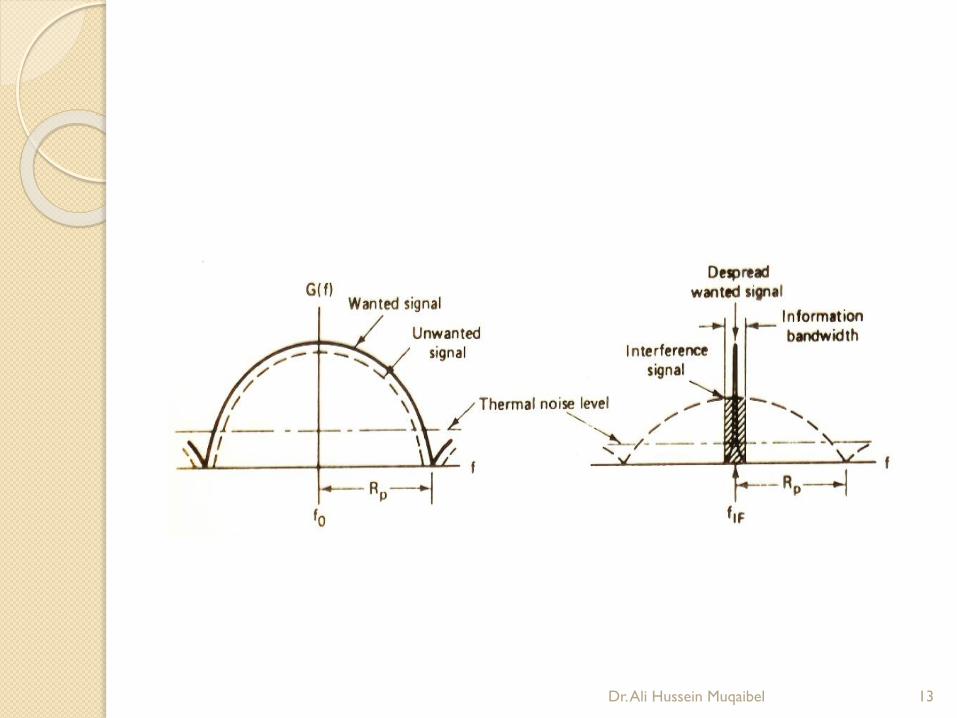
Tone Jamming (cont.) Despreading spreads the jammer power
and despreads the signal power:
Dr. Ali Hussein Muqaibel 14

Tone Jamming (cont.)
Filtering (at the BW of the phase modulator)
after despreading suppresses the jammer
power:
Dr. Ali Hussein Muqaibel 15

DSSS
Revisit the model, and assume BPSK
𝐼𝑛𝑓𝑜𝑟𝑚𝑎𝑡𝑖𝑜𝑛 𝑅𝑎𝑡𝑒 = 𝑅 𝑏𝑖𝑡𝑠/sec.
𝐴𝑣𝑖𝑎𝑙𝑎𝑏𝑙𝑒 𝐵𝑎𝑛𝑑𝑤𝑖𝑑𝑡ℎ = 𝑊 𝐻𝑧.
The phase of the carrier is shifted
pseudo-randomly according to the
pattern from PN generator at a rate
𝑊 𝑡𝑖𝑚𝑒𝑠/sec.𝑊 = 1/𝑇𝑐
𝑇𝑐 : duration of the phase chip interval (Basic
element in DSSS)
𝑇𝑏 = 1/𝑅
𝑇𝑏 : duration of a rectangular pulse (time of
transmission for a bit)
Dr. Ali Hussein Muqaibel 16

Bandwidth Expansion Factor
Bandwidth Expansion Factor:
𝐵𝑒 = 𝑊/𝑅 = 𝑇𝑏 /𝑇𝑐
In practice 𝑇𝑏 /𝑇𝑐 is integer.
𝐿𝑐 = # 𝑜𝑓 𝑐ℎ𝑖𝑝𝑠 𝑝𝑒𝑟 𝑖𝑛𝑓𝑜. 𝑏𝑖𝑡. =
# of phase shifts during one bit
transmission.
Using (𝑛, 𝑘) = (𝑘𝐿𝑐 , 𝑘) code.
To transmit 𝑛 chips, the time available
in 𝑘 𝑇𝑏
The code rate (block, convolutional):
𝑅𝑐 =𝑘
𝑛=
1
𝐿𝑐
Dr. Ali Hussein Muqaibel 17

DS-QPSK Modulator
Dr. Ali Hussein Muqaibel 18

• Bandwidth of 𝑝 𝑡 =1
𝑇𝑐
• Bandwidth of 𝑔 𝑡 =1
𝑇
• Bandwidth of 𝑝 𝑡 𝑔 𝑡 =1
𝑇+
1
𝑇𝑐
≈1
𝑇𝐶Dr. Ali Hussein Muqaibel 19

Forming the DS (Modulator)
Let 𝑏𝑖 = 𝑖𝑡ℎ bit of PN sequence. (0,1)
𝑐𝑖 = 𝑖𝑡ℎ bit from the encoder.
𝑎𝑖 = 𝑏𝑖 + 𝑐𝑖 (same → 𝑎𝑖 = 0, otherwise 𝑎𝑖 = 1)
then use a BPSK modulator.
𝑔𝑖 𝑡 = 𝑔 𝑡 − 𝑖𝑇𝑐 (𝑎𝑖 = 0)
−𝑔 𝑡 − 𝑖𝑇𝑐 (𝑎𝑖 = 1)
(kLc ,k)
encoder
Modulation
g(t)+
Info.
sequence
k bits/unit
time
Coded
sequence
kLc
bits /time
PN Seq.
kLc bits/time
𝑐𝑖
𝑏𝑖
𝑎𝑖
Dr. Ali Hussein Muqaibel 20

Alternative Modulator Modulation of 𝑐𝑖’s first
𝑐𝑖 (𝑡) = (2 𝑐𝑖 − 1) 𝑔(𝑡 − 𝑖𝑇𝑐)
output of PN sequence
𝑝𝑖 (𝑡) = (2 𝑏𝑖 − 1) 𝑝(𝑡 − 𝑖𝑇𝑐)
Multiplying Both
𝑔𝑖 (𝑡) = (2 𝑏𝑖 − 1) (2 𝑐𝑖 − 1) 𝑔(𝑡 − 𝑖𝑇𝑐)
Modulation
g(t)+
PN Seq. waveform
with square pulse
shape
Coded
Seq.
Dr. Ali Hussein Muqaibel 21
x
𝑝𝑖(𝑡)
𝑐𝑖 (𝑡)𝑔𝑖 (𝑡)

Equivalence of the two modulators
𝑏𝑖 𝑐𝑖 𝑎𝑖 = 𝑏𝑖 ⨁ 𝑐𝑖 𝑔𝑖
(1) (2 𝑏𝑖 − 1) (2 𝑐𝑖 − 1) 𝒈𝒊(𝟐)
0 0 0 𝑔(𝑡) 1 𝑔(𝑡)
0 1 1 − 𝑔(𝑡) -1 − 𝑔(𝑡)
1 0 1 − 𝑔(𝑡) -1 − 𝑔(𝑡)
1 1 0 𝑔(𝑡) 1 𝑔(𝑡)
• The two modulators are equivalent and can be used for coded or uncoded
systems
• The first is easier to implement.
• The second is easier to relate to demodulation
(kLc ,k)
encoder
Modulation
g(t)+
Info.
sequence
k bits/unit
time
Coded
sequence
kLc
bits /time
PN Seq.
kLc bits/time
Modulation
g(t)+
PN Seq. waveform
with square pulse
shape
Coded
Seq. x
Dr. Ali Hussein Muqaibel 22
𝑝𝑖(𝑡)
𝑐𝑖 (𝑡) 𝑔𝑖(2)
𝑐𝑖
𝑏𝑖
𝑎𝑖
𝑔𝑖1

Demodulator
The received signal for the 𝑗𝑡ℎ code element
“ no de-spreading yet ”
𝑟𝑗 (𝑡) = 𝑃𝑗 (𝑡) 𝑐𝑗 (𝑡) + 𝑧 (𝑡)
= (2 𝑏𝑗 − 1) (2 𝑐𝑗 − 1) 𝑔 (𝑡 − 𝑗 𝑇𝑐) + 𝑧 (𝑡)
𝑧(𝑡) assumed to be stationary random process
with zero mean)
Dr. Ali Hussein Muqaibel 23

Possible Demodulator structures for PN spread spectrum signals.
Dr. Ali Hussein Muqaibel 24

Demodulation
Multiply by (2𝑏𝑖 − 1) takes out the effect of the PN sequence.
In modulator (b) we are multiply before filtering.
In modulator (c) we are using a correlatorinstead of a matched filter.
Optimality of matched filter assume “Gaussianity”◦ If 𝑧(𝑡) is not Gaussian>>> no optimality
◦ If noise distribution is not known, we still can use it.
Dr. Ali Hussein Muqaibel 25

Error Rate Performance of
Detector of the DecoderThe processing gain & the Jamming margin.
𝐸𝑏 = 𝑃𝑎𝑣 𝑇𝑏 =𝑃𝑎𝑣
𝑅𝐸𝑏 : Energy per bit in term of average power (𝑃𝑎𝑣).
𝑇𝑏 : bit interval.𝑃𝑎𝑣
𝐽𝑎𝑣
: signal to jamming power ratio.
𝐽0 : the power spectral density (PSD) for the jamming signal. (+𝑁0)
𝐽0 =𝐽𝑎𝑣
𝑊.
𝐸𝑏
𝐽0
= 𝑃𝑎𝑣
𝑅/ 𝐽
𝑎𝑣
𝑊=
𝑊
𝑅/(𝐽𝑎𝑣/𝑃𝑎𝑣)
𝑊/𝑅 = 𝑇𝑏/ 𝑇𝑐 = 𝐵𝑐 = 𝐿𝑐 = 𝐺𝑝
𝑃𝑟𝑜𝑐𝑒𝑠𝑠𝑖𝑛𝑔 𝐺𝑎𝑖𝑛 (𝐺𝑝)
Dr. Ali Hussein Muqaibel 26

Processing Gain, SJR, and Jamming
Margin Processing gain (𝐺𝑝) : the advantage gained over the jammer that
is obtained by expanding the BW of the transmitted signal.
Let 𝐸𝑏
𝐽0
be interpreted as SNR (SJR) required for a specific error
rate performance and
𝑊
𝑅available bandwidth expansion factor.
𝐽𝑎𝑣
𝑃𝑎𝑣
Jamming margin of DSSS system i.e the largest value that 𝐽𝑎𝑣
𝑃𝑎𝑣
can take and still satisfy the probability of error, 𝑃𝑒 .
The total average interference power is 𝐽𝑎𝑣 = 2𝐽0𝑊, where 𝐽0 is
the value of the power spectral density of an equivalent wideband
interference.
𝐸𝑏
𝐽0= 2
𝑊
𝑅/
𝐽𝑎𝑣
𝑃𝑎𝑣
Dr. Ali Hussein Muqaibel 27

Example (To be checked)
Suppose we wish to maintain 𝑃𝑒 ≤ 10−6 , the system has 𝑊/𝑅 = 500. What is the Jamming margin ?
For 𝑃𝑒 = 10−6 we require 𝐸𝑏 / 𝐽0 = 10.5 𝑑𝐵.
𝐺𝑝 = 30 𝑑𝐵
So , Jamming margin = 33 – 10.5 = 22.5 𝑑𝐵.
That is the received signal can be detected reliably (at 10−6) even when the interference is up to 100times the received signal.
One can design the system for a given Jamming margin.
Dr. Ali Hussein Muqaibel 28

In Class Exercise
A user is communicating with a satellite using a
signal of power = 20𝑑𝐵𝑊. A jammer is
transmitting 60𝑑𝐵𝑊 (continuous, full-band).
The needed transmission rate is 100 𝑏/𝑠. The
required 𝐸𝑏
𝐽0
is 10 𝑑𝐵.
Find the required bandwidth?
Dr. Ali Hussein Muqaibel 29
User