SPRAY GUN TROUBLESHOOTING AND PREVENTIVE MAINTENANCE … guide.pdf · SPRAY GUN TROUBLESHOOTING AND...
12
SERVICE BULLETIN SB-2-001-F Replaces SB-2-001-E IMPORTANT: Before using this equipment, read all safety precautions and instructions in this manual. Keep for future use. SPRAY GUN TROUBLESHOOTING AND PREVENTIVE MAINTENANCE GUIDE
-
Upload
truongduong -
Category
Documents
-
view
263 -
download
1
Transcript of SPRAY GUN TROUBLESHOOTING AND PREVENTIVE MAINTENANCE … guide.pdf · SPRAY GUN TROUBLESHOOTING AND...

SERVICE BULLETIN
SB-2-001-FReplaces SB-2-001-E
IMPORTANT: Before using this equipment, read allsafety precautions and instructions in this manual.Keep for future use.
SPRAY GUN TROUBLESHOOTING ANDPREVENTIVE MAINTENANCE GUIDE
Page 2 SB-2-001-F
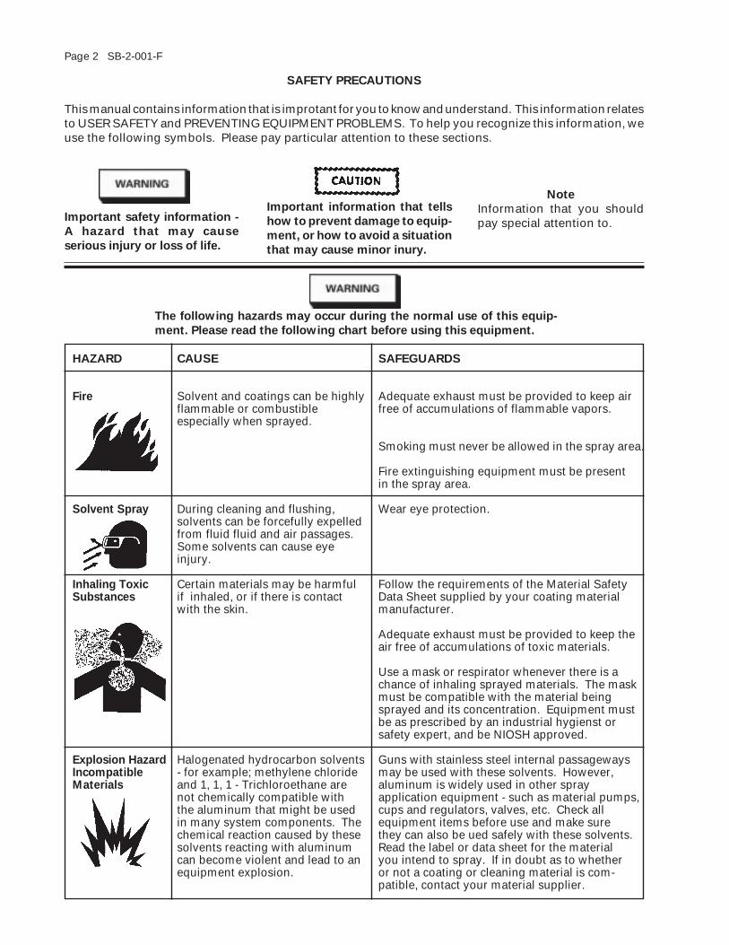
HAZARD CAUSE SAFEGUARDS
Fire Solvent and coatings can be highly Adequate exhaust must be provided to keep airflammable or combustible free of accumulations of flammable vapors.especially when sprayed.
Smoking must never be allowed in the spray area.
Fire extinguishing equipment must be presentin the spray area.
Solvent Spray During cleaning and flushing, Wear eye protection.solvents can be forcefully expelledfrom fluid fluid and air passages.Some solvents can cause eyeinjury.
Inhaling Toxic Certain materials may be harmful Follow the requirements of the Material SafetySubstances if inhaled, or if there is contact Data Sheet supplied by your coating material
with the skin. manufacturer.
Adequate exhaust must be provided to keep theair free of accumulations of toxic materials.
Use a mask or respirator whenever there is achance of inhaling sprayed materials. The maskmust be compatible with the material beingsprayed and its concentration. Equipment mustbe as prescribed by an industrial hygienst orsafety expert, and be NIOSH approved.
Explosion Hazard Halogenated hydrocarbon solvents Guns with stainless steel internal passagewaysIncompatible - for example; methylene chloride may be used with these solvents. However,Materials and 1, 1, 1 - Trichloroethane are aluminum is widely used in other spray
not chemically compatible with application equipment - such as material pumps,the aluminum that might be used cups and regulators, valves, etc. Check allin many system components. The equipment items before use and make surechemical reaction caused by these they can also be ued safely with these solvents.solvents reacting with aluminum Read the label or data sheet for the materialcan become violent and lead to an you intend to spray. If in doubt as to whetherequipment explosion. or not a coating or cleaning material is com-
patible, contact your material supplier.
SAFETY PRECAUTIONS
This manual contains information that is improtant for you to know and understand. This information relatesto USER SAFETY and PREVENTING EQUIPMENT PROBLEMS. To help you recognize this information, weuse the following symbols. Please pay particular attention to these sections.
Important information that tells
how to prevent damage to equip-
ment, or how to avoid a situation
that may cause minor inury.
Note
Information that you shouldpay special attention to.Important safety information -
A hazard that may cause
serious injury or loss of life.
The following hazards may occur during the normal use of this equip-
ment. Please read the following chart before using this equipment.
SB-2-001-F Page 3
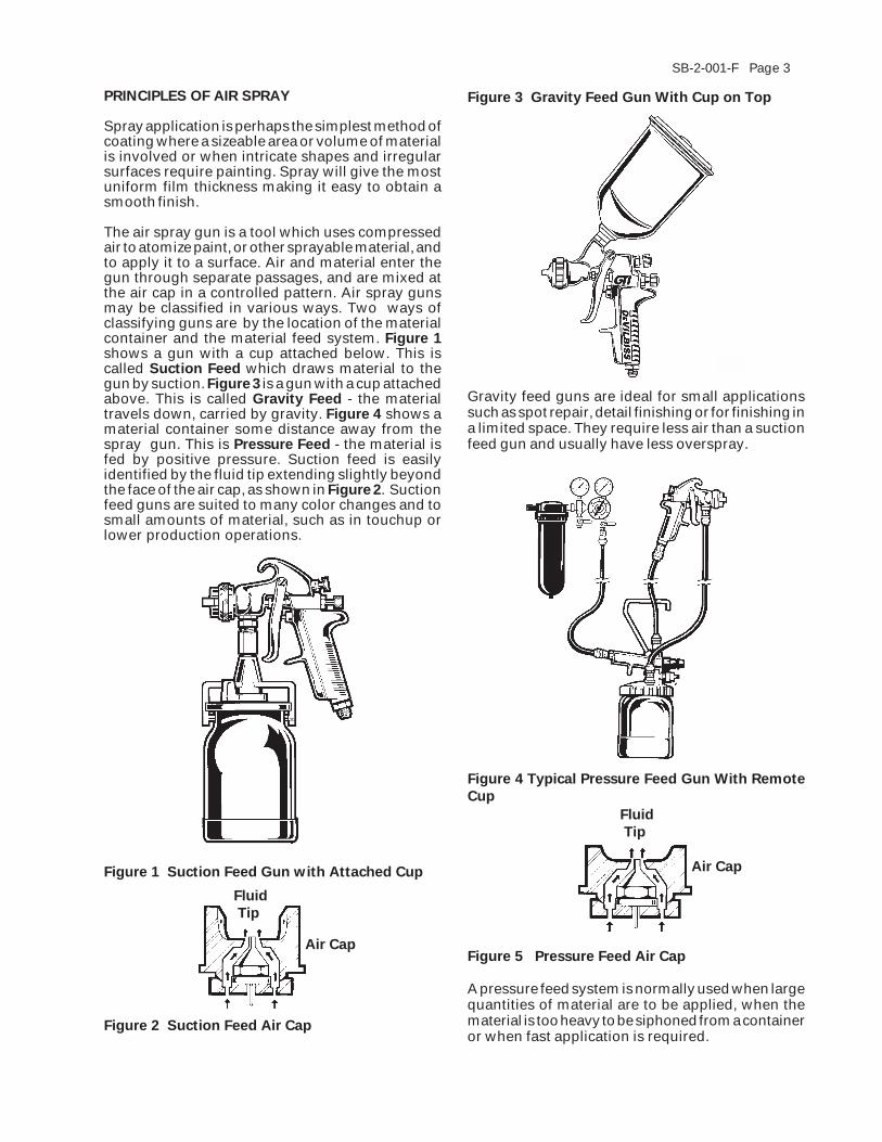
Figure 3 Gravity Feed Gun With Cup on Top
Gravity feed guns are ideal for small applicationssuch as spot repair, detail finishing or for finishing ina limited space. They require less air than a suctionfeed gun and usually have less overspray.
A pressure feed system is normally used when largequantities of material are to be applied, when thematerial is too heavy to be siphoned from a containeror when fast application is required.
Figure 5 Pressure Feed Air Cap
PRINCIPLES OF AIR SPRAY
Spray application is perhaps the simplest method ofcoating where a sizeable area or volume of materialis involved or when intricate shapes and irregularsurfaces require painting. Spray will give the mostuniform film thickness making it easy to obtain asmooth finish.
The air spray gun is a tool which uses compressedair to atomize paint, or other sprayable material, andto apply it to a surface. Air and material enter thegun through separate passages, and are mixed atthe air cap in a controlled pattern. Air spray gunsmay be classified in various ways. Two ways ofclassifying guns are by the location of the materialcontainer and the material feed system. Figure 1shows a gun with a cup attached below. This iscalled Suction Feed which draws material to thegun by suction. Figure 3 is a gun with a cup attachedabove. This is called Gravity Feed - the materialtravels down, carried by gravity. Figure 4 shows amaterial container some distance away from thespray gun. This is Pressure Feed - the material isfed by positive pressure. Suction feed is easilyidentified by the fluid tip extending slightly beyondthe face of the air cap, as shown in Figure 2. Suctionfeed guns are suited to many color changes and tosmall amounts of material, such as in touchup orlower production operations.
Figure 2 Suction Feed Air Cap
Figure 4 Typical Pressure Feed Gun With Remote
Cup
Figure 1 Suction Feed Gun with Attached Cup
Fluid
Tip
Air Cap
Air Cap
Fluid
Tip
Page 4 SB-2-001-F
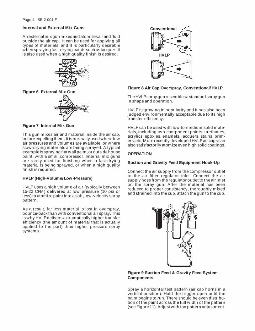
Internal and External Mix Guns
An external mix gun mixes and atomizes air and fluidoutside the air cap. It can be used for applying alltypes of materials, and it is particularly desirablewhen spraying fast-drying paints such as lacquer. Itis also used when a high quality finish is desired.
Figure 6 External Mix Gun
Figure 7 Internal Mix Gun
This gun mixes air and material inside the air cap,before expelling them. It is normally used where lowair pressures and volumes are available, or whereslow-drying materials are being sprayed. A typicalexample is spraying flat wall paint, or outside housepaint, with a small compressor. Internal mix gunsare rarely used for finishing when a fast-dryingmaterial is being sprayed, or when a high qualityfinish is required.
HVLP (High-Volume/Low-Pressure)
HVLP uses a high volume of air (typically between15-22 CFM) delivered at low pressure (10 psi orless) to atomize paint into a soft, low-velocity spraypattern.
As a result, far less material is lost in overspray,bounce-back than with conventional air spray. Thisis why HVLP delivers a dramatically higher transferefficiency (the amount of material that is actuallyapplied to the part) than higher pressure spraysystems.
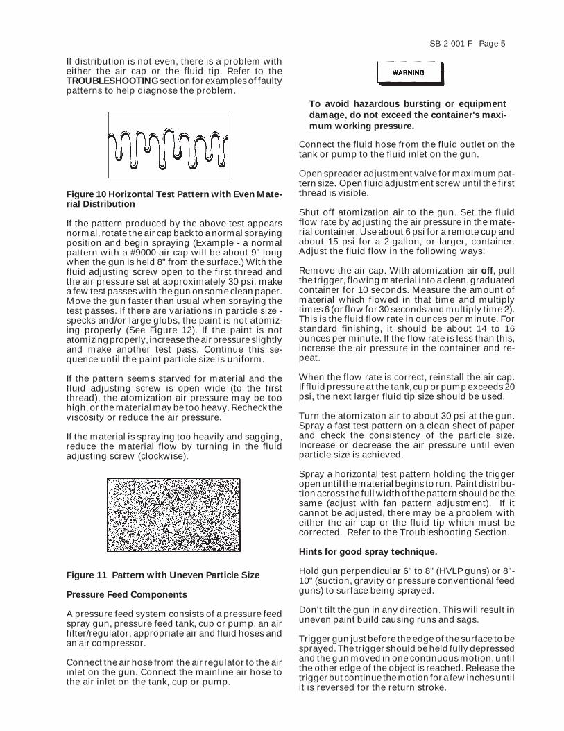
Spray a horizontal test pattern (air cap horns in avertical position). Hold the trigger open until thepaint begins to run. There should be even distribu-tion of the paint across the full width of the pattern(see Figure 11). Adjust with fan pattern adjustment.
Figure 9 Suction Feed & Gravity Feed System
Components
Figure 8 Air Cap Overspray, Conventional/HVLP
The HVLP spray gun resembles a standard spray gunin shape and operation.
HVLP is growing in popularity and it has also beenjudged environmentally acceptable due to its hightransfer efficiency.
HVLP can be used with low to-medium solid mate-rials, including two-component paints, urethanes,acrylics, epoxies, enamels, lacquers, stains, prim-ers, etc. More recently developed HVLP air caps canalso satisfactorily atomize even high solid coatings.
OPERATION
Suction and Gravity Feed Equipment Hook-Up
Connect the air supply from the compressor outletto the air filter regulator inlet. Connect the airsupply hose from the regulator outlet to the air inleton the spray gun. After the material has beenreduced to proper consistency, thoroughly mixedand strained into the cup, attach the gun to the cup.
HVLP
Conventional
SB-2-001-F Page 5
Figure 10 Horizontal Test Pattern with Even Mate-rial Distribution
If the pattern produced by the above test appearsnormal, rotate the air cap back to a normal sprayingposition and begin spraying (Example - a normalpattern with a #9000 air cap will be about 9" longwhen the gun is held 8" from the surface.) With thefluid adjusting screw open to the first thread andthe air pressure set at approximately 30 psi, makea few test passes with the gun on some clean paper.Move the gun faster than usual when spraying thetest passes. If there are variations in particle size -specks and/or large globs, the paint is not atomiz-ing properly (See Figure 12). If the paint is notatomizing properly, increase the air pressure slightlyand make another test pass. Continue this se-quence until the paint particle size is uniform.
If the pattern seems starved for material and thefluid adjusting screw is open wide (to the firstthread), the atomization air pressure may be toohigh, or the material may be too heavy. Recheck theviscosity or reduce the air pressure.
If the material is spraying too heavily and sagging,reduce the material flow by turning in the fluidadjusting screw (clockwise).
Figure 11 Pattern with Uneven Particle Size
Pressure Feed Components
A pressure feed system consists of a pressure feedspray gun, pressure feed tank, cup or pump, an airfilter/regulator, appropriate air and fluid hoses andan air compressor.
Connect the air hose from the air regulator to the airinlet on the gun. Connect the mainline air hose tothe air inlet on the tank, cup or pump.
To avoid hazardous bursting or equipment
damage, do not exceed the container's maxi-
mum working pressure.
Connect the fluid hose from the fluid outlet on thetank or pump to the fluid inlet on the gun.
Open spreader adjustment valve for maximum pat-tern size. Open fluid adjustment screw until the firstthread is visible.
Shut off atomization air to the gun. Set the fluidflow rate by adjusting the air pressure in the mate-rial container. Use about 6 psi for a remote cup andabout 15 psi for a 2-gallon, or larger, container.Adjust the fluid flow in the following ways:
Remove the air cap. With atomization air off, pullthe trigger, flowing material into a clean, graduatedcontainer for 10 seconds. Measure the amount ofmaterial which flowed in that time and multiplytimes 6 (or flow for 30 seconds and multiply time 2).This is the fluid flow rate in ounces per minute. Forstandard finishing, it should be about 14 to 16ounces per minute. If the flow rate is less than this,increase the air pressure in the container and re-peat.
When the flow rate is correct, reinstall the air cap.If fluid pressure at the tank, cup or pump exceeds 20psi, the next larger fluid tip size should be used.
Turn the atomizaton air to about 30 psi at the gun.Spray a fast test pattern on a clean sheet of paperand check the consistency of the particle size.Increase or decrease the air pressure until evenparticle size is achieved.
Spray a horizontal test pattern holding the triggeropen until the material begins to run. Paint distribu-tion across the full width of the pattern should be thesame (adjust with fan pattern adjustment). If itcannot be adjusted, there may be a problem witheither the air cap or the fluid tip which must becorrected. Refer to the Troubleshooting Section.
Hints for good spray technique.
Hold gun perpendicular 6" to 8" (HVLP guns) or 8"-10" (suction, gravity or pressure conventional feedguns) to surface being sprayed.
Don't tilt the gun in any direction. This will result inuneven paint build causing runs and sags.
Trigger gun just before the edge of the surface to besprayed. The trigger should be held fully depressedand the gun moved in one continuous motion, untilthe other edge of the object is reached. Release thetrigger but continue the motion for a few inches untilit is reversed for the return stroke.
If distribution is not even, there is a problem witheither the air cap or the fluid tip. Refer to theTROUBLESHOOTING section for examples of faultypatterns to help diagnose the problem.
Page 6 SB-2-001-F
REPLACEMENT OF PARTS
Follow specific gun Service Bulletin exploded viewfor replacing parts. There are areas requiring propersequence.
The fan adjustment assembly should only be in-stalled after turning the knob out. If left in, the stemor needle could jam against the seat.
Pull trigger or remove fluid adjusting screw prior totip tightening. Tip and needle damage can occur.
Spray guns have some combination of plastic,copper, leather and soft packings and gaskets. It isrecommended that these be replaced if the assem-bly is removed or when doing an overall repair. Thefluid needle packing must be replaced when thepacking nut bottoms out.
It is recommended to oil a new packing or needlebefore assembly. Packing nuts should be tightenedjust enough to seal (fluid leakage on pressure feed,suction of air on suction feed). Too tight will bindthe needle as well as shorten life of packing. Whenreplacing the fluid tip or fluid needle, it is recom-
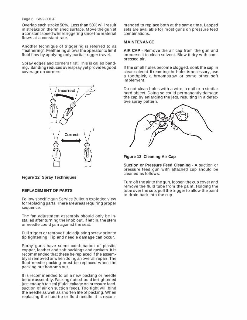
Overlap each stroke 50%. Less than 50% will resultin streaks on the finished surface. Move the gun ata constant speed while triggering since the materialflows at a constant rate.
Another technique of triggering is referred to as"feathering". Feathering allows the operator to limitfluid flow by applying only partial trigger travel.
Spray edges and corners first. This is called band-ing. Banding reduces overspray yet provides goodcoverage on corners.
Figure 12 Spray Techniques
Correct
Incorrect
mended to replace both at the same time. Lappedsets are available for most guns on pressure feedcombinations.
MAINTENANCE
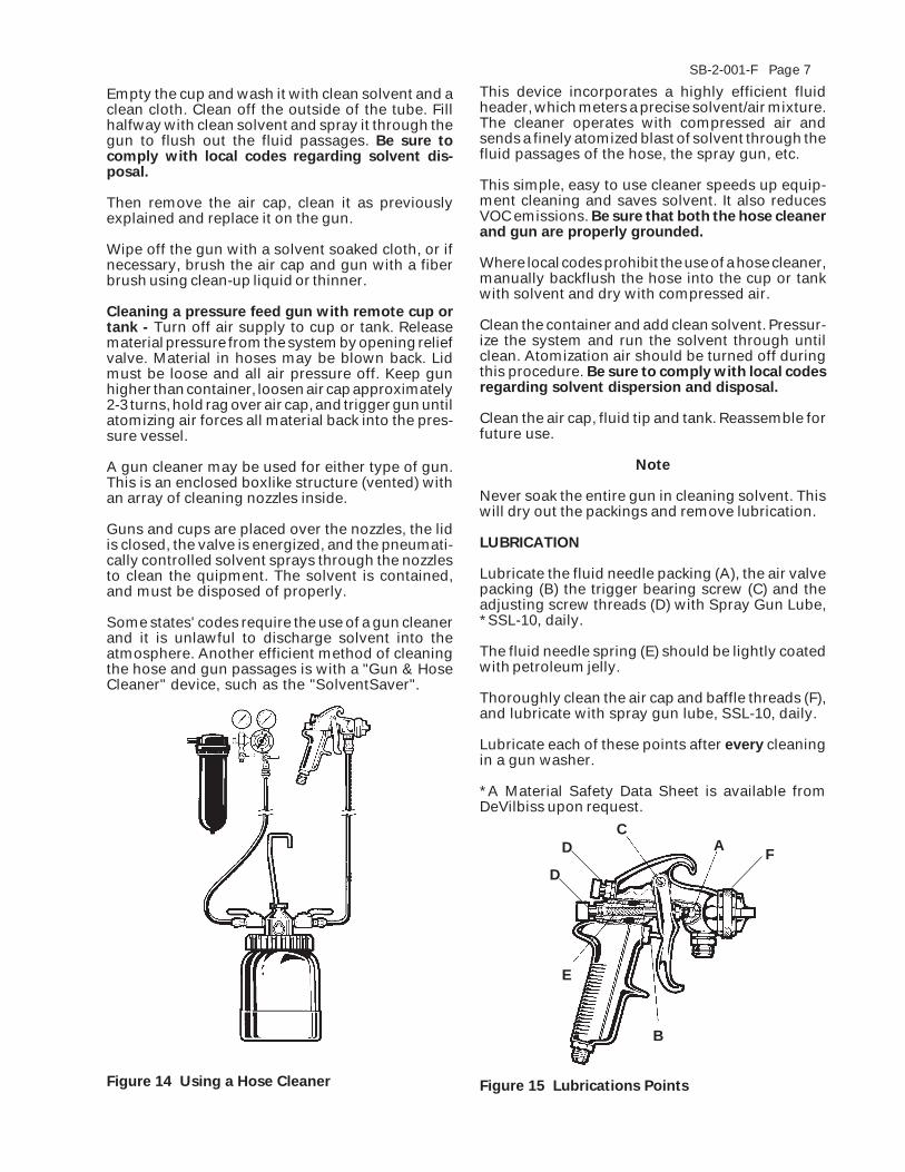
AIR CAP - Remove the air cap from the gun andimmerse it in clean solvent. Blow it dry with com-pressed air.
If the small holes become clogged, soak the cap inclean solvent. If reaming the holes is necessary, usea toothpick, a broomstraw or some other softimplement.
Do not clean holes with a wire, a nail or a similarhard object. Doing so could permanently damagethe cap by enlarging the jets, resulting in a defec-tive spray pattern.
Figure 13 Cleaning Air Cap
Suction or Pressure Feed Cleaning - A suction orpressure feed gun with attached cup should becleaned as follows:
Turn off the air to the gun, loosen the cup cover andremove the fluid tube from the paint. Holding thetube over the cup, pull the trigger to allow the paintto drain back into the cup.
SB-2-001-F Page 7
This device incorporates a highly efficient fluidheader, which meters a precise solvent/air mixture.The cleaner operates with compressed air andsends a finely atomized blast of solvent through thefluid passages of the hose, the spray gun, etc.
This simple, easy to use cleaner speeds up equip-ment cleaning and saves solvent. It also reducesVOC emissions. Be sure that both the hose cleanerand gun are properly grounded.
Where local codes prohibit the use of a hose cleaner,manually backflush the hose into the cup or tankwith solvent and dry with compressed air.
Clean the container and add clean solvent. Pressur-ize the system and run the solvent through untilclean. Atomization air should be turned off duringthis procedure. Be sure to comply with local codesregarding solvent dispersion and disposal.
Clean the air cap, fluid tip and tank. Reassemble forfuture use.
Note
Never soak the entire gun in cleaning solvent. Thiswill dry out the packings and remove lubrication.
LUBRICATION
Lubricate the fluid needle packing (A), the air valvepacking (B) the trigger bearing screw (C) and theadjusting screw threads (D) with Spray Gun Lube,*SSL-10, daily.
The fluid needle spring (E) should be lightly coatedwith petroleum jelly.
Thoroughly clean the air cap and baffle threads (F),and lubricate with spray gun lube, SSL-10, daily.
Lubricate each of these points after every cleaningin a gun washer.
*A Material Safety Data Sheet is available fromDeVilbiss upon request.
Figure 14 Using a Hose Cleaner
Empty the cup and wash it with clean solvent and aclean cloth. Clean off the outside of the tube. Fillhalfway with clean solvent and spray it through thegun to flush out the fluid passages. Be sure tocomply with local codes regarding solvent dis-posal.
Then remove the air cap, clean it as previouslyexplained and replace it on the gun.
Wipe off the gun with a solvent soaked cloth, or ifnecessary, brush the air cap and gun with a fiberbrush using clean-up liquid or thinner.
Cleaning a pressure feed gun with remote cup ortank - Turn off air supply to cup or tank. Releasematerial pressure from the system by opening reliefvalve. Material in hoses may be blown back. Lidmust be loose and all air pressure off. Keep gunhigher than container, loosen air cap approximately2-3 turns, hold rag over air cap, and trigger gun untilatomizing air forces all material back into the pres-sure vessel.
A gun cleaner may be used for either type of gun.This is an enclosed boxlike structure (vented) withan array of cleaning nozzles inside.
Guns and cups are placed over the nozzles, the lidis closed, the valve is energized, and the pneumati-cally controlled solvent sprays through the nozzlesto clean the quipment. The solvent is contained,and must be disposed of properly.
Some states' codes require the use of a gun cleanerand it is unlawful to discharge solvent into theatmosphere. Another efficient method of cleaningthe hose and gun passages is with a "Gun & HoseCleaner" device, such as the "SolventSaver".
Figure 15 Lubrications Points
F
B
E
D
D
CA

Page 8 SB-2-001-F
TROUBLESHOOTING
CONDITION CAUSE CORRECTION
Heavy top or bottom pattern Horn holes plugged. Clean. Ream with non-metallicpoint.
Obstruction on top or bottom of Clean.fluid tip.
Cap and/or tip seat dirty. Clean.
Heavy right or left Left or right side horn holes plugged. Clean. Ream with non-metallicside pattern point.
Dirt on left or right side of fluid tip. Clean.
Remedies for the top-heavy, bottom-heavy, right-heavy and left-heavy patterns:1) Determine if the obstruction is on the air cap or the fluid tip. Do this by makinga test spray pattern. Then, rotate the cap one-half turn and spray anotherpattern. If the defect is inverted, obstruction is on the air cap. Clean the air capas previously instructed.2) If the defect is not inverted, it is on the fluid tip. Check for a fine burr on theedge of the fluid tip. Remove with #600 wet or dry sand paper.3) Check for dried paint just inside the opening. Remove paint by washing withsolvent.
Heavy center pattern Fluid pressure too high for atomization Balance air and fluid pressure.air (pressure feed)). Increase spray pattern width with
spreader adjustment valve.
Material flow exceeds air cap's capacity. Thin or lower fluid flow.
Atomizing pressure too low. Increase pressure.
Material too thick. Thin to proper consistency.
Split spray pattern Fluid adjusting knob turned in too far. Back out counterclockwise toachieve proper pattern.
Atomization air pressure too high. Reduce at transformer.
Fluid pressure too low (pressure feed only). Increase fluid pressure.
Spreader adjusting valve set too high. Adjust.
Suction And Pressure FeedJerky or fluttering spray
*Loose or damaged fluid tip/seat. Tighten or replace.
Material level too low. Refill.
Container tipped too far. Hold more upright.
Obstruction in fluid passage. Backflush with solvent.
Loose or broken fluid tube or fluid Tighten or replace.inlet nipple.
Dry or loose fluid needle packing nut. Lubricate or tighten.
*Most common problem.
SB-2-001-F Page 9
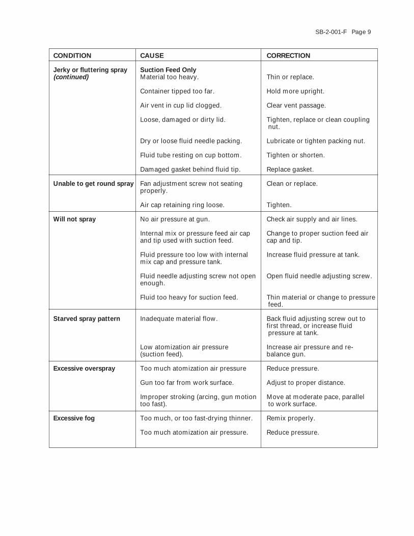
CONDITION CAUSE CORRECTION
Jerky or fluttering spray Suction Feed Only(continued) Material too heavy. Thin or replace.
Container tipped too far. Hold more upright.
Air vent in cup lid clogged. Clear vent passage.
Loose, damaged or dirty lid. Tighten, replace or clean couplingnut.
Dry or loose fluid needle packing. Lubricate or tighten packing nut.
Fluid tube resting on cup bottom. Tighten or shorten.
Damaged gasket behind fluid tip. Replace gasket.
Unable to get round spray Fan adjustment screw not seating Clean or replace.properly.
Air cap retaining ring loose. Tighten.
Will not spray No air pressure at gun. Check air supply and air lines.
Internal mix or pressure feed air cap Change to proper suction feed airand tip used with suction feed. cap and tip.
Fluid pressure too low with internal Increase fluid pressure at tank.mix cap and pressure tank.
Fluid needle adjusting screw not open Open fluid needle adjusting screw.enough.
Fluid too heavy for suction feed. Thin material or change to pressurefeed.
Starved spray pattern Inadequate material flow. Back fluid adjusting screw out tofirst thread, or increase fluidpressure at tank.
Low atomization air pressure Increase air pressure and re-(suction feed). balance gun.
Excessive overspray Too much atomization air pressure Reduce pressure.
Gun too far from work surface. Adjust to proper distance.
Improper stroking (arcing, gun motion Move at moderate pace, paralleltoo fast). to work surface.
Excessive fog Too much, or too fast-drying thinner. Remix properly.
Too much atomization air pressure. Reduce pressure.
Page 10 SB-2-001-F
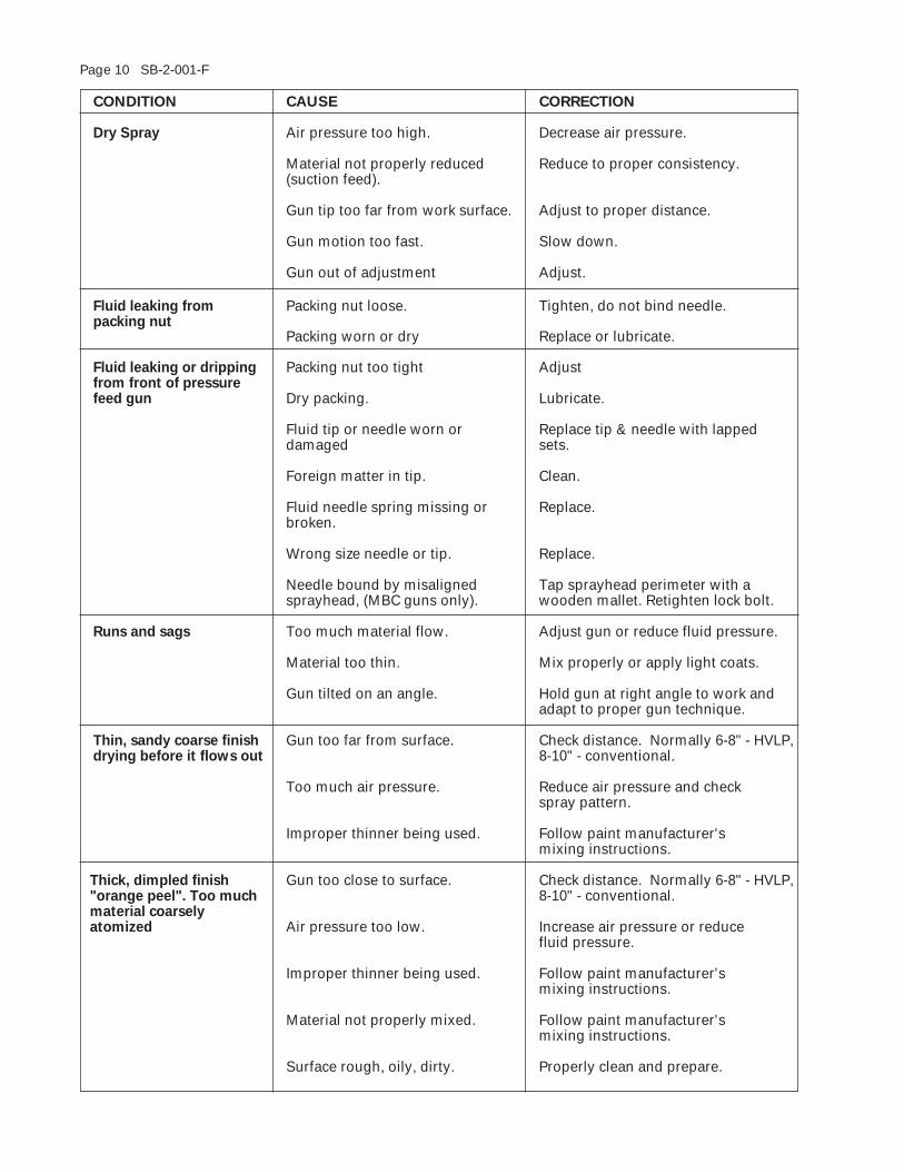
CONDITION CAUSE CORRECTION
Dry Spray Air pressure too high. Decrease air pressure.
Material not properly reduced Reduce to proper consistency.(suction feed).
Gun tip too far from work surface. Adjust to proper distance.
Gun motion too fast. Slow down.
Gun out of adjustment Adjust.
Fluid leaking from Packing nut loose. Tighten, do not bind needle.packing nut
Packing worn or dry Replace or lubricate.
Fluid leaking or dripping Packing nut too tight Adjustfrom front of pressurefeed gun Dry packing. Lubricate.
Fluid tip or needle worn or Replace tip & needle with lappeddamaged sets.
Foreign matter in tip. Clean.
Fluid needle spring missing or Replace.broken.
Wrong size needle or tip. Replace.
Needle bound by misaligned Tap sprayhead perimeter with asprayhead, (MBC guns only). wooden mallet. Retighten lock bolt.
Runs and sags Too much material flow. Adjust gun or reduce fluid pressure.
Material too thin. Mix properly or apply light coats.
Gun tilted on an angle. Hold gun at right angle to work andadapt to proper gun technique.
Thin, sandy coarse finish Gun too far from surface. Check distance. Normally 6-8" - HVLP,drying before it flows out 8-10" - conventional.
Too much air pressure. Reduce air pressure and checkspray pattern.
Improper thinner being used. Follow paint manufacturer'smixing instructions.
Thick, dimpled finish Gun too close to surface. Check distance. Normally 6-8" - HVLP,"orange peel". Too much 8-10" - conventional.material coarselyatomized Air pressure too low. Increase air pressure or reduce
fluid pressure.
Improper thinner being used. Follow paint manufacturer'smixing instructions.
Material not properly mixed. Follow paint manufacturer'smixing instructions.
Surface rough, oily, dirty. Properly clean and prepare.
SB-2-001-F Page 11
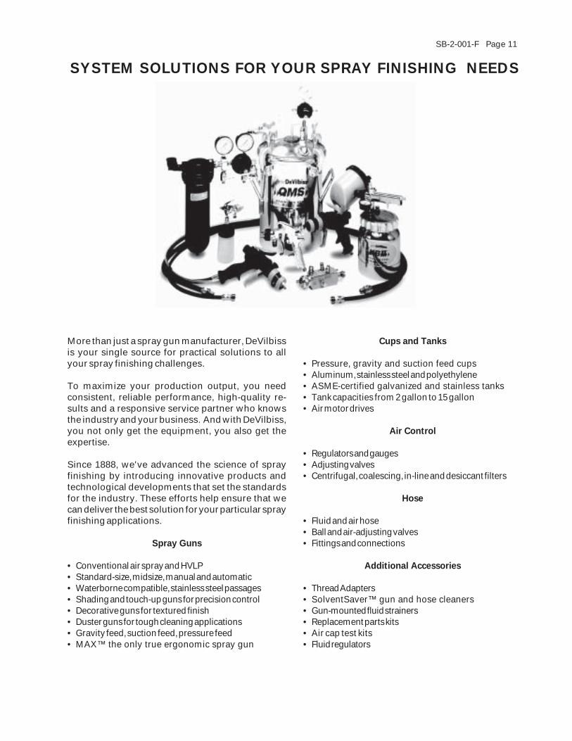
More than just a spray gun manufacturer, DeVilbissis your single source for practical solutions to allyour spray finishing challenges.
To maximize your production output, you needconsistent, reliable performance, high-quality re-sults and a responsive service partner who knowsthe industry and your business. And with DeVilbiss,you not only get the equipment, you also get theexpertise.
Since 1888, we've advanced the science of sprayfinishing by introducing innovative products andtechnological developments that set the standardsfor the industry. These efforts help ensure that wecan deliver the best solution for your particular sprayfinishing applications.
Spray Guns
• Conventional air spray and HVLP• Standard-size, midsize, manual and automatic• Waterborne compatible, stainless steel passages• Shading and touch-up guns for precision control• Decorative guns for textured finish• Duster guns for tough cleaning applications• Gravity feed, suction feed, pressure feed• MAX™ the only true ergonomic spray gun
Cups and Tanks
• Pressure, gravity and suction feed cups• Aluminum, stainless steel and polyethylene• ASME-certified galvanized and stainless tanks• Tank capacities from 2 gallon to 15 gallon• Air motor drives
Air Control
• Regulators and gauges• Adjusting valves• Centrifugal, coalescing, in-line and desiccant filters
Hose
• Fluid and air hose• Ball and air-adjusting valves• Fittings and connections
Additional Accessories
• Thread Adapters• SolventSaver™ gun and hose cleaners• Gun-mounted fluid strainers• Replacement parts kits• Air cap test kits• Fluid regulators
SYSTEM SOLUTIONS FOR YOUR SPRAY FINISHING NEEDS
Page 12 SB-2-001-F
3/01 ©Copyright 2001, DeVilbiss Printed in U.S.A.
DeVILBISS WORLDWIDE SALES AND SERVICE LISTING - www.devilbiss.com
INDUSTRIAL FINISHINGDeVilbiss has authorized distributors throughout the world. FOR TECHNICAL ASSISTANCE OR THE DISTRIBUTOR
NEAREST YOU, CALL TOLL FREE 1-888-992-4657 (U.S.A. AND CANADA ONLY). FOR LOCAL CALLS, SEE LISTING
BELOW.
U.S./Canada Sales & Customer Service Office Address Telephone No.GLENDALE HEIGHTS, IL 60139 195 Internationale Blvd. (630) 237-5000
Toll Free Fax No. 1-877-790-6965
AUTOMOTIVE REFINISHINGDeVilbiss has authorized distributors throughout the world. For equipment, parts and service, check the Yellow Pagesunder "Automobile Body Shop Equipment and Supplies". FOR TECHNICAL ASSISTANCE, CALL TOLL FREE
1-800-445-3988 (U.S.A. ONLY). FOR LOCAL CALLS, SEE LISTING BELOW.
U.S. Customer Service Office Address Telephone No.MAUMEE, OH 43537 1724 Indian Wood Circle (419) 891-8100
Toll Free Fax No. 1-800-445-6643