Spot Weld Al Equipment. Resistance Welding Lesson Objectives When you finish this lesson you will...
40
Spot Weld Al Equipment
-
Upload
vanessa-dean -
Category
Documents
-
view
214 -
download
0
Transcript of Spot Weld Al Equipment. Resistance Welding Lesson Objectives When you finish this lesson you will...

Spot Weld Al Equipment
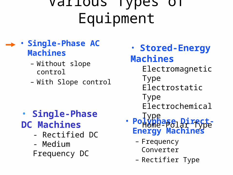
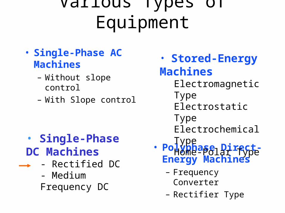
Various Types of Equipment
• Single-Phase AC Machines– Without slope control
– With Slope control
• Polyphase Direct-Energy Machines– Frequency Converter
– Rectifier Type
• Stored-Energy Machines
Electromagnetic TypeElectrostatic TypeElectrochemical TypeHome-Polar Type
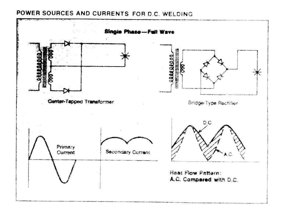
• Single-Phase DC Machines
- Rectified DC- Medium Frequency DC
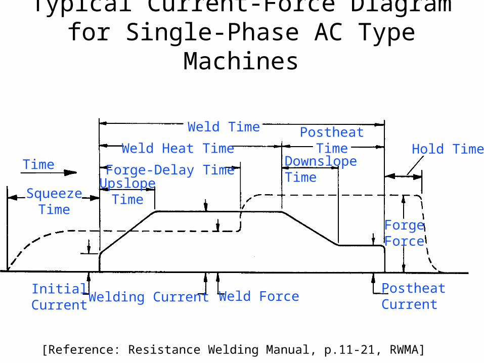
Typical Current-Force Diagram for Single-Phase AC Type Machines
Weld Time
Weld Heat TimePostheat
Time Hold Time
ForgeForce
Forge-Delay TimeUpslope
Time
DownslopeTime
Weld ForcePostheatCurrentWelding Current
InitialCurrent
Time
SqueezeTime
[Reference: Resistance Welding Manual, p.11-21, RWMA]
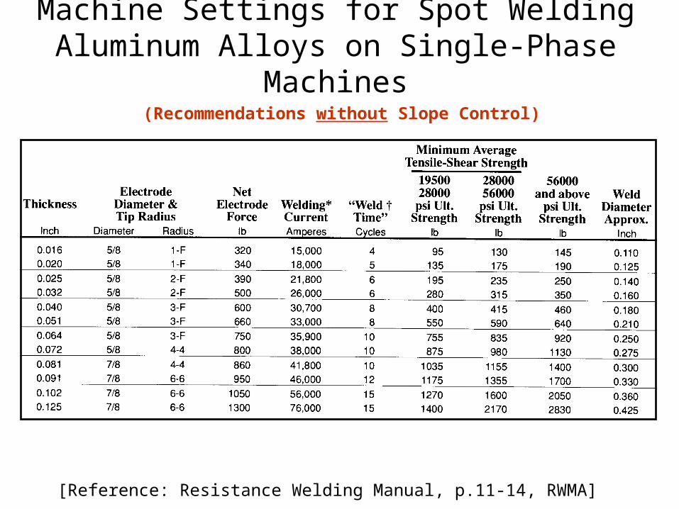
Machine Settings for Spot Welding Aluminum Alloys on Single-Phase Machines
[Reference: Resistance Welding Manual, p.11-14, RWMA]
(Recommendations without Slope Control)
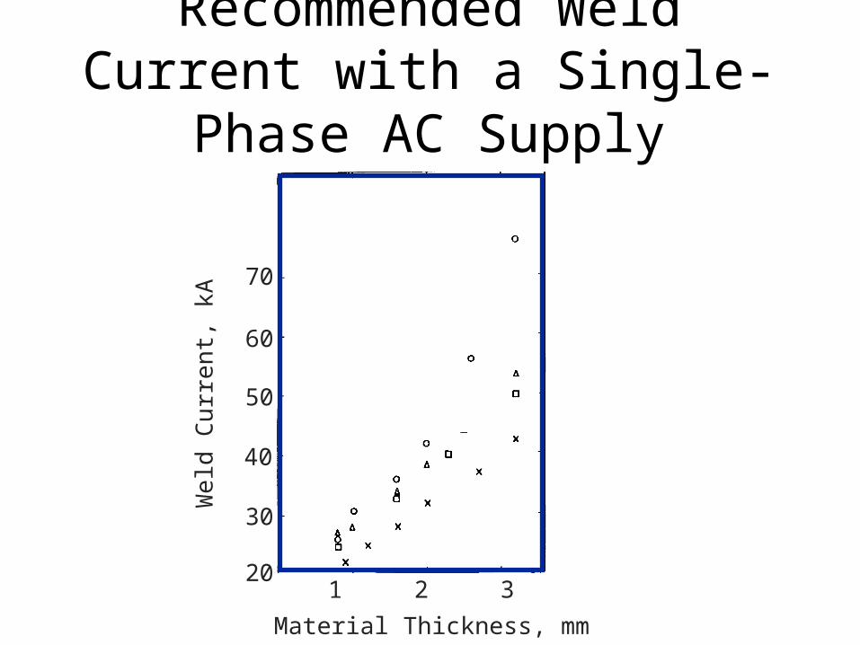
Recommended Weld Current with a Single-Phase AC Supply
1 2 3
Material Thickness, mm
70
60
50
40
30
20
We
ld C
urr
ent,
kA

Recommended Electrode Force with a Single-Phase AC Supply
Material Thickness, mm
Ele
ctro
de
Fo
rce,
kN
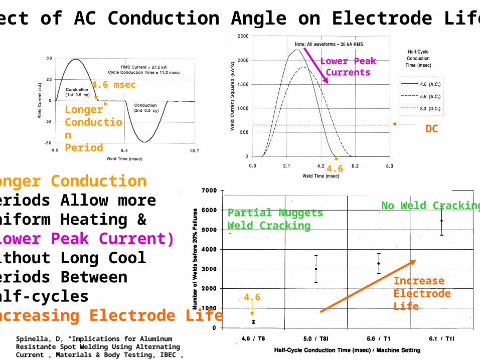
Effect of AC Conduction Angle on Electrode Life
Longer ConductionPeriods Allow moreUniform Heating &(Lower Peak Current)Without Long Cool Periods BetweenHalf-cyclesIncreasing Electrode Life
4.6 msec
4.6
4.6
DC
Lower PeakCurrents
LongerConductionPeriod
IncreaseElectrodeLife
Spinella, D, “Implications for Aluminum Resistance Spot Welding Using Alternating Current”, Materials & Body Testing, IBEC , 1995
Partial NuggetsWeld Cracking
No Weld Cracking
Various Types of Equipment
• Single-Phase AC Machines– Without slope control
– With Slope control
• Polyphase Direct-Energy Machines– Frequency Converter
– Rectifier Type
• Stored-Energy Machines
Electromagnetic TypeElectrostatic TypeElectrochemical TypeHome-Polar Type
• Single-Phase DC Machines
- Rectified DC- Medium Frequency DC
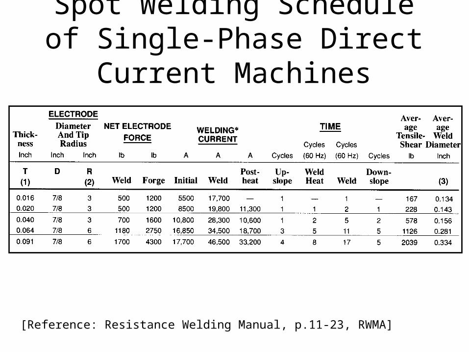
Spot Welding Schedule of Single-Phase Direct Current Machines
[Reference: Resistance Welding Manual, p.11-23, RWMA]
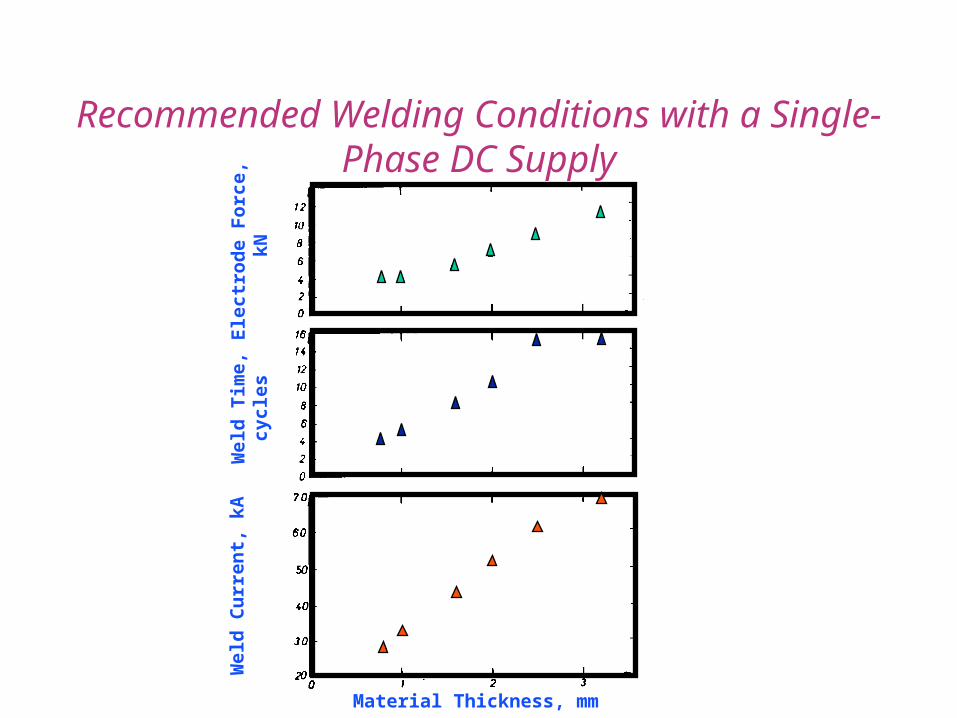
Material Thickness, mm
Wel
d C
urr
en
t, k
AW
eld
Tim
e,
cyc
les
Ele
ctro
de
Fo
rce,
kN
Recommended Welding Conditions with a Single-Phase DC Supply

Effect of DC Current on Electrode Life
DC Results in Off Center WeldMore Wear on One Electrode
Kumagai, M, High Performance Electrode Material…IBEC’95, Material & Body Testing, 1995
Electrode Face with HigherOperating Temperature

Various Types of Equipment
• Single-Phase AC Machines– Without slope control
– With Slope control
• Polyphase Direct-Energy Machines– Frequency Converter
– Rectifier Type
• Stored-Energy Machines
Electromagnetic TypeElectrostatic TypeElectrochemical TypeHome-Polar Type
• Single-Phase DC Machines
- Rectified DC- Medium Frequency DC

Newton, et al, Fund of RW Aluminum,AWS, SMWC VI Oct 1994
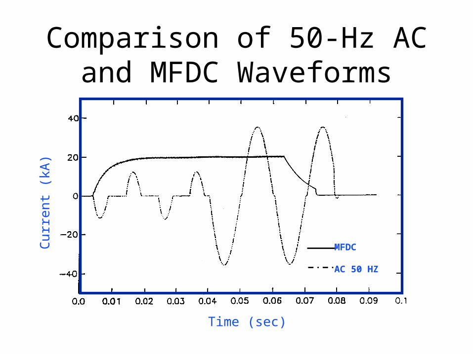
Comparison of 50-Hz AC and MFDC Waveforms
MFDC
AC 50 HZ
Time (sec)
Cu
rre
nt (
kA)

AC Mid-Frequency DC
61114-T4 Aluminum
Michaud, E, A Comparison of AC & MFDCSMWC VII, AWS, 1996
ReducedExpulsion

Weld Current
Wel
d Ti
me
ACMF DC

Increase Force
As Increase Gage, Lobe Moves
Effect of Force and Gage on Lobe for MF DC
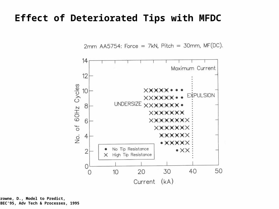
Browne, D., Model to Predict,IBEC’95, Adv Tech & Processes, 1995

Browne, D., Model to Predict,IBEC’95, Adv Tech & Processes, 1995
Effect of Electrode Tip Diameters on MFDC

Browne, D., Model to Predict,IBEC’95, Adv Tech & Processes, 1995
Effect of Weld Spacing in MFDC
Browne, D., Model to Predict,IBEC’95, Adv Tech & Processes, 1995
Effect of Deteriorated Tips with MFDC

Various Types of Equipment
• Single-Phase AC Machines– Without slope control
– With Slope control
• Polyphase Direct-Energy Machines– Frequency Converter
– Rectifier Type
• Stored-Energy Machines
Electromagnetic TypeElectrostatic TypeElectrochemical TypeHome-Polar Type
• Single-Phase DC Machines
- Rectified DC- Medium Frequency DC
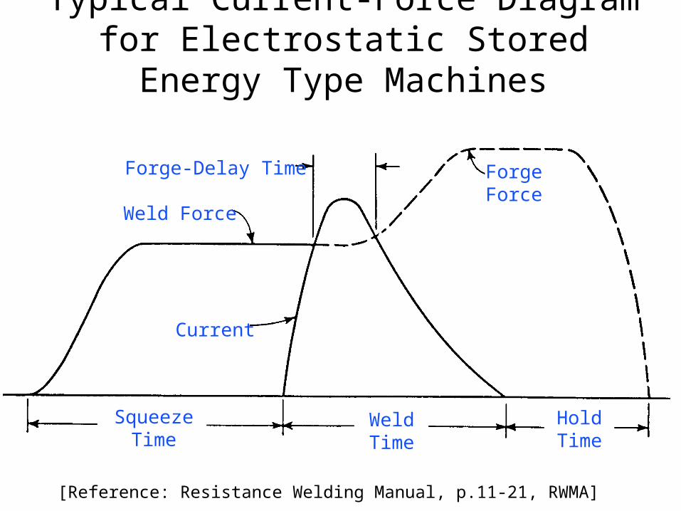
Typical Current-Force Diagram for Electrostatic Stored Energy Type Machines
SqueezeTime
WeldTime
HoldTime
Current
ForgeForce
Forge-Delay Time
Weld Force
[Reference: Resistance Welding Manual, p.11-21, RWMA]

Spot Welding Schedule of Electrostatic Stored Energy Machines
[Reference: Resistance Welding Manual, p.11-23, RWMA]

Various Types of Equipment
• Single-Phase AC Machines– Without slope control
– With Slope control
• Polyphase Direct-Energy Machines– Frequency Converter
– Rectifier Type
• Stored-Energy Machines
Electromagnetic TypeElectrostatic TypeElectrochemical TypeHome-Polar Type
• Single-Phase DC Machines
- Rectified DC- Medium Frequency DC

Insert diagram of Frequency Converter waveform

Spot Welding Schedule of Typical Three-Phase Frequency Converter
[Reference: Resistance Welding Manual, p.11-22, RWMA]

Various Types of Equipment
• Single-Phase AC Machines– Without slope control
– With Slope control
• Polyphase Direct-Energy Machines– Frequency Converter
– Rectifier Type
• Stored-Energy Machines
Electromagnetic TypeElectrostatic TypeElectrochemical TypeHome-Polar Type
• Single-Phase DC Machines
- Rectified DC- Medium Frequency DC

Typical Current-Force Diagram for Three-Phase Rectifier Type Machines
[Reference: Resistance Welding Manual, p.11-20, RWMA]
Final Force
HoldTime
Total WeldTime
PostheatCurrent
Initial Force
Welding Current
Weld Time
Forge-DelayTime
SqueezeTime
PostheatTime

Spot Welding Schedule of Typical Three-Phase Direct Current Rectifier
[Reference: Resistance Welding Manual, p.11-22, RWMA]

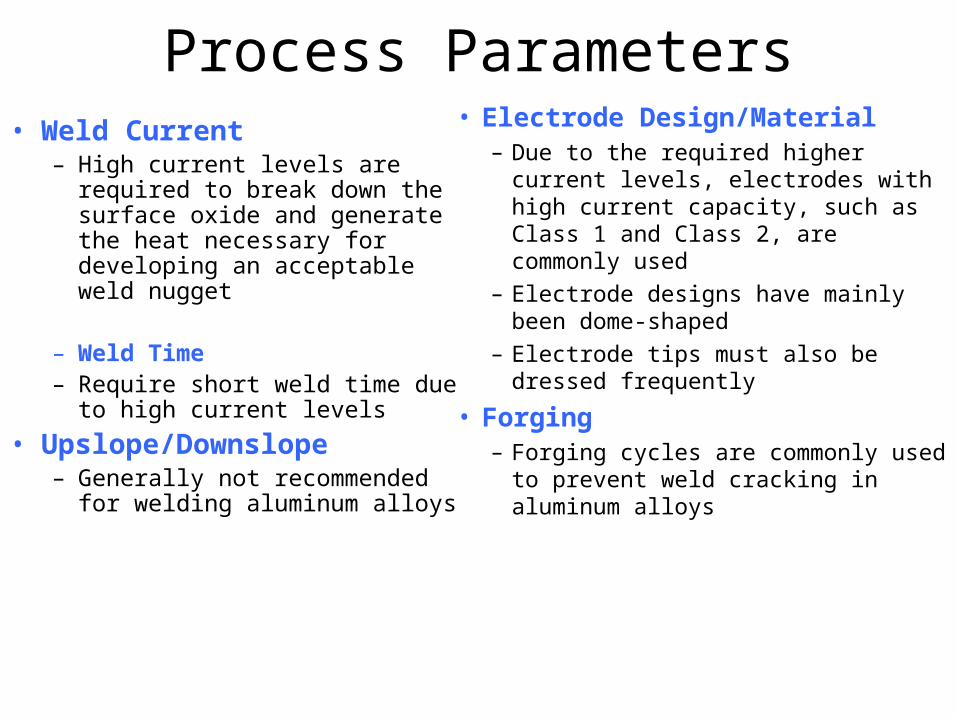
Process Parameters• Weld Current
– High current levels are required to break down the surface oxide and generate the heat necessary for developing an acceptable weld nugget
– Weld Time– Require short weld time due to
high current levels
• Upslope/Downslope– Generally not recommended for
welding aluminum alloys
• Electrode Design/Material– Due to the required higher current levels,
electrodes with high current capacity, such as Class 1 and Class 2, are commonly used
– Electrode designs have mainly been dome-shaped
– Electrode tips must also be dressed frequently
• Forging– Forging cycles are commonly used to
prevent weld cracking in aluminum alloys
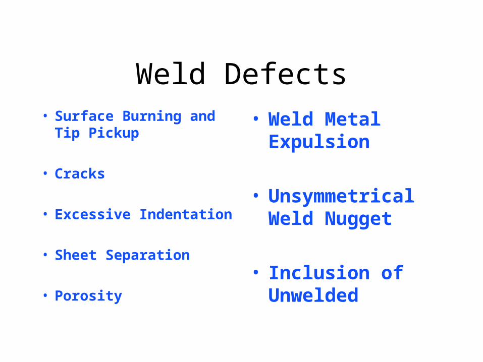
Weld Defects• Surface Burning and Tip
Pickup
• Cracks
• Excessive Indentation
• Sheet Separation
• Porosity
• Weld Metal Expulsion
• Unsymmetrical Weld Nugget
• Inclusion of Unwelded

Surface Burning and Tip Pickup
[Cause]• Surface burning is caused by
excessive heat on the metal surface under the electrode and is indicated by burned, pitted and discolored welds.
• Excessive electrode pickup is caused primarily by the same factors.
[Remedy Those Conditions]• Improper surface conditions• Electrode skidding• Improper Electrode
Material - conductivity too low
• Dirty or improper cleaned electrodes
• Excessive “weld time”• Excessive welding current• Inadequate welding force

Cracks[Cause]
• Internal and external cracks in welds, generally caused by improper thermal and pressure conditions, are observed in the weld structure and surface, respectively.
[Remedy Those Conditions]
• Excessive penetration• Insufficient force• Improper rate of current rise• Improper electrode cooling• Improper electrode contour• Delayed application of
forging force• Electrode skidding

Excessive Indentation
[Cause]
• Excessive indentation, generally caused by improper force application, is indicated by depression on the weld surface.
[Remedy Those Conditions]
• Excessive force• Weld metal expulsion• Improper electrode contour• Excessive surface heating• Improper forging cycle• Excessive Welding Current

Sheet Separation[Cause]
• Excessive sheet separation, generally caused by poor fitup of parts and excessive surface deformation, is indicated by a wide separation of the base metal adjacent to the weld.
[Remedy Those Conditions]
• Excessive force
• Improper fitup of parts
• Weld metal expulsion
• Incorrect electrode contour
• Excessive welding current
• Tip misalignment
• Excessive “weld time”
Porosity[Cause]
• A porous weld structure, generally caused by improper application of heat and force, is observed by sectioning and etching the weld.
[Remedy Those Conditions]
• Insufficient “weld time”• Improper rate of current rise• Improper electrode contour• Incorrect sequencing of weld
and forging force• Insufficient force
Weld Metal Expulsion
[Cause]
• Weld expulsion, generally caused by extreme heat and improper force, is indicated by expelled metal from the weld.
[Remedy Those Conditions]
• Insufficient force• Tip misalignment• Erratic contact resistance• Foreign substance at faying
surface• Electrode skidding• Excessive welding current• Excessive “weld time”
Unsymmetrical Weld Nugget[Cause]
• Unsymmetrical welds, generally caused by unsymmetrical gauge combination, improper electrode contour, poor fitting workpiece or surface preparation, may be observed by sectioning the weld.
[Remedy Those Conditions]
• Improper electrode contour• Inadequate surface preparation• Improper fitup of workpieces• Electrode misalignment• Electrode skidding