Sport V Owners Manual - Mud Buddy V Owners Manual.pdf · ! 2!!!...
16
1 Quick Start Guide Models V 3600, 4000, 4400 & 5000 October 2014 All V4400 and 5000 models must use 91 or higher Octane fuel. Break In Procedures: Do not run the engine more than half throttle the first hour. Do not run the engine at full throttle for over five minutes the next three hours.= Mounting Fuel Battery Oil Start Switch Trim Switches Handle Adjust Starting Travel Lock and Strap Running Service Schedule Emergency Trim, Start and Shift Procedures
Transcript of Sport V Owners Manual - Mud Buddy V Owners Manual.pdf · ! 2!!!...

1
Quick Start Guide
Models V 3600, 4000, 4400 & 5000 October 2014
All V4400 and 5000 models must use 91 or higher Octane fuel.
Break In Procedures:
Do not run the engine more than half throttle the first hour. Do not run the engine at full throttle for over five minutes the next three hours.=
-‐ Mounting -‐ Fuel -‐ Battery -‐ Oil -‐ Start Switch -‐ Trim Switches -‐ Handle Adjust -‐ Starting -‐ Travel Lock and Strap -‐ Running -‐ Service Schedule -‐ Emergency Trim, Start and Shift Procedures

2
Thank you for buying the most advanced backwater outboard motor. Please read this quick start manual, drive safely and let others know where you are going and when you will return. Mounting: Your motor is shipped with six mounting bolts. Use a hoist capable of handling 350 pounds to safely lift the engine from the crate on to the boat. Align the motor to the center of the boat, mark the mounting holes and drill using a 3/8” drill bit. You must mount the motor using the top and bottom bolts as shown. The motor mount has additional mounting holes to choose the remaining two bolt mounting position. Use silicone to seal the bolt holes. Do not over tighten the bolts and crush the bolt. Break In: There is no more important period of operation that the break of your new motor. Model 3600 and 4000 motors should be broke in over a 4 hour period. During the first hour you should not run full throttle. For the next three hours, you should not run full throttle for more than five minutes. All models should run at varied throttle positions allowing the engine to cool as parts break in. Model 4400 and 5000 require a valve adjustment at five hours. This is the owner’s responsibility. See page 11 for instructions. Change the oil initially at 20 hours. Failure to break in the engine properly will result in overheating and engine damage not covered by warranty. Fuel and Storage: It is important to use a fuel stabilizer whenever the engine is not being used for more than two weeks. There is no warranty on fuel systems and damage incurred by improper storage. Your motor is shipped with a 5’ fuel hose. Connect this to an approved marine fuel tank using the clamps included. Do not use a quick disconnect fuel hose which can restrict fuel delivery. You can use a marine primer bulb, however do not excessively pump the primer bulb as it can damage the carburetor. If you are using a forward mounted fuel tank, use a minimum size 5/16” fuel hose. Use a minimum of 87 Octane fuel for the 3600 and 4000 models. Use a minimum 91 Octane fuel for the model 4400 Black Death and 5000 Magnum engines. Use Stabil or an equivalent brand fuel additive if you are storing the engine for more than one month.

3
Handle: Secure the engine handle using a boat strap or the bungee provided with each engine.
Engine Tie Down and Transom Saver: You must use a transom saver and tie down straps when trailering to prevent severe damage to the motor. Do not tie the engine off to one side – center the propeller on the transom. Battery: Use a group 27 or larger battery with at least 550 cranking amps. Oil: You engine holds 2 quarts of oil. We ship the engine with no oil, however some oil from assembly may be in the engine. Add oil slowly and check the dipstick with the engine in a level position. We recommend running a non-‐synthetic break in oil for 20 hours and then a synthetic blend 10W-‐30 oil. We recommend using 5W-‐30 synthetic blend oil in the 44 and 52 models. Start Switch: The start key switch is located on the handle. It has three positions, off, on and start. You can use the emergency shut off to stop the engine, but you must turn the key to the off position to prevent battery drain. Trim Switches: You Sport V is equipped with two trim switches, one on the handle end and another on the side of the handle near the key switch. The handle end trim switch is used when running the motor and the side handle switch is used for emergency trim and for trimming the engine from the ground. Caution: Pinch Point -‐ Do not place your hands anywhere near the mount when trimming the engine.
4
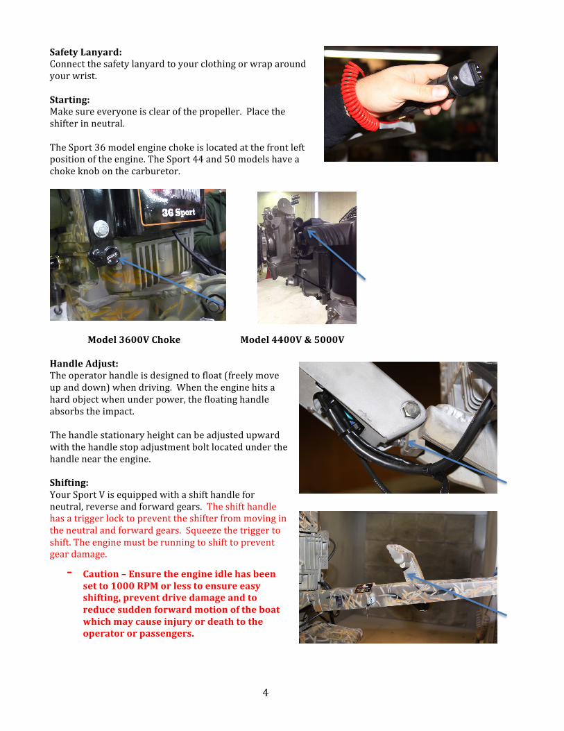
Safety Lanyard: Connect the safety lanyard to your clothing or wrap around your wrist. Starting: Make sure everyone is clear of the propeller. Place the shifter in neutral. The Sport 36 model engine choke is located at the front left position of the engine. The Sport 44 and 50 models have a choke knob on the carburetor.
Model 3600V Choke Model 4400V & 5000V Handle Adjust: The operator handle is designed to float (freely move up and down) when driving. When the engine hits a hard object when under power, the floating handle absorbs the impact. The handle stationary height can be adjusted upward with the handle stop adjustment bolt located under the handle near the engine. Shifting: Your Sport V is equipped with a shift handle for neutral, reverse and forward gears. The shift handle has a trigger lock to prevent the shifter from moving in the neutral and forward gears. Squeeze the trigger to shift. The engine must be running to shift to prevent gear damage.
-‐ Caution – Ensure the engine idle has been set to 1000 RPM or less to ensure easy shifting, prevent drive damage and to reduce sudden forward motion of the boat which may cause injury or death to the operator or passengers.
5
-‐ Always stop and start the motor in the neutral gear.
-‐ Always shift with the engine running at idle which should be 1000 RPM or less.
Squeeze the trigger and move the handle toward the engine to go into reverse. Move the handle towards the front of the boat to move forward. Again, do not shift unless the engine is running or for an emergency. Shifting when the engine is off can cause damage to the shift cable.
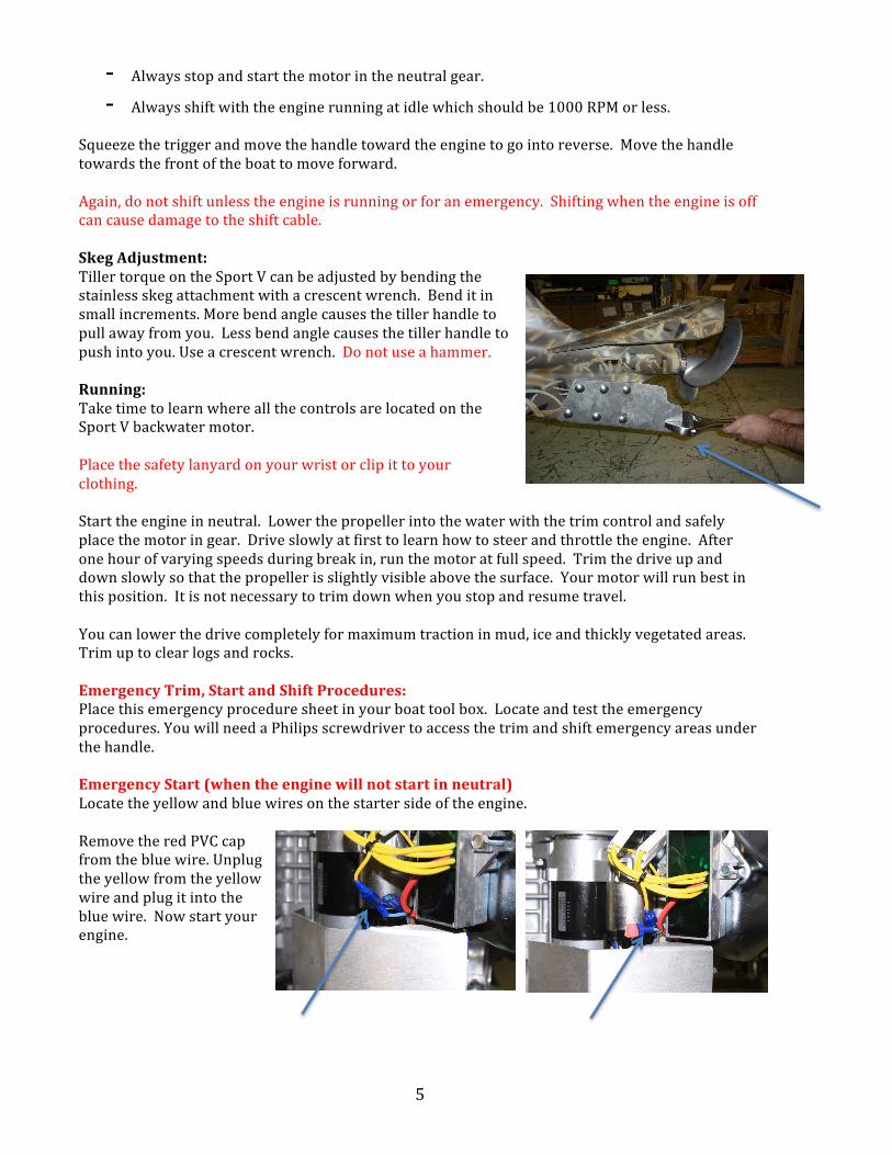
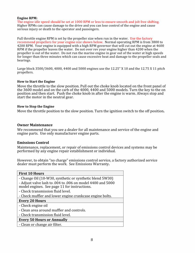
Skeg Adjustment: Tiller torque on the Sport V can be adjusted by bending the stainless skeg attachment with a crescent wrench. Bend it in small increments. More bend angle causes the tiller handle to pull away from you. Less bend angle causes the tiller handle to push into you. Use a crescent wrench. Do not use a hammer. Running: Take time to learn where all the controls are located on the Sport V backwater motor. Place the safety lanyard on your wrist or clip it to your clothing. Start the engine in neutral. Lower the propeller into the water with the trim control and safely place the motor in gear. Drive slowly at first to learn how to steer and throttle the engine. After one hour of varying speeds during break in, run the motor at full speed. Trim the drive up and down slowly so that the propeller is slightly visible above the surface. Your motor will run best in this position. It is not necessary to trim down when you stop and resume travel. You can lower the drive completely for maximum traction in mud, ice and thickly vegetated areas. Trim up to clear logs and rocks. Emergency Trim, Start and Shift Procedures: Place this emergency procedure sheet in your boat tool box. Locate and test the emergency procedures. You will need a Philips screwdriver to access the trim and shift emergency areas under the handle. Emergency Start (when the engine will not start in neutral) Locate the yellow and blue wires on the starter side of the engine. Remove the red PVC cap from the blue wire. Unplug the yellow from the yellow wire and plug it into the blue wire. Now start your engine.

6
Emergency Trim: Remove the cover from the underside of the handle. Disconnect the blue and green trim wires as shown. Place one end of the blue trim wire on the starter battery cable and the green on any part of the engine where it will ground. The trim should move up or down. Reverse the wires to go the other direction.
Emergency Shift: If you break a shift cable or can’t shift, remove the rear inspection plate under the muffler. Locate the shift arm. Remove the shift cable pin. Rotate the shift arm towards the propeller to go forward. See the Emergency start procedure above to connect the start over-‐ride. You can now start the engine in gear. Be very careful. Simply turn the engine off to stop.
Caution: Owner’s Responsibility The following items are the responsibility of the owner. Failure to maintain the drive and engine will result in the loss of the part and product warranty.
-‐ Break in the Engine Carefully. Do not run full throttle for the first hour and no more than five minutes for the next three hours. Failure to follow this procedure will result in overheating and engine seal damage.
-‐ Proper storage of engine using fuel stabilizer. Stale fuel will cause damage to the carburetor and will result in difficult starting, poor idle, acceleration and top end speed. Poor fuel delivery can cause an engine lean condition and may affect the performance and life of the engine. Always use a fuel stabilizer like Stabil when the engine is stored for more than one month.
-‐ Propeller balance and condition. If a propeller is worn, damaged or bent, it will vibrate and can cause the following conditions. Loose bolts, handle vibration, leaking seals, bearing failure, frame cracking and engine damage. A damaged propeller will cause engine and frame damage and is not covered by warranty.

7
-‐ Freezing rain and snow can cause severe damage to the throttle and carburetor. Store the motor with a cover. Throttle damage and a sticking cable will result in a broken throttle cable, frayed cable and sticking cable.
-‐ Salt can cause extensive corrosion to the drive and engine. Ensure the product is cleaned and lubricated every time it is run in salt water. A sacrificial anode has been installed on the lower end of the motor transom mount and will minimize corrosion damage however all corrosion must be removed. Corrosion will cause misfiring, poor electrical switch and breaker and connections and engine failure. Remove and repaint and areas that have corrosion. Use silicone spray protectant on wire connections.
-‐ Drive seal damage will result in loss of fluid level in the transmission, difficult shifting, bearing failure and ultimately failure of the entire drive system. Maintain fluid levels and monitor the condition of the seals near the propeller.
-‐ Bolts, nuts and other fasteners should be checked frequently to prevent early drive and engine failure.
-‐ Impacts can cause engine and drive damage. This includes prop and skeg damage, oil cooler and hose damage, throttle and kill switch breakage. Severe impacts can cause carburetor and air filter separation. Snags can break fuel pumps, hoses and pull the dipstick off the engine. These motors are built tough, but caution and safety should be your main concern when running in waters with unknown depth and bottom conditions. Severe impacts that cause frame and engine damage are not covered by warranty.
Sport V Engine Owner’s Manual Oil Recommendations We recommend the use of a good quality 10W30 or synthetic blend 5W30 oil classified for service SF,SG,SH, SJ or higher. Do not use special additives. Check Oil Place the engine in a flat position. Clean the oil fill area of any debris. Remove the dipstick and wipe with a clean cloth. Insert the dipstick fully. Remove the dipstick and check the oil level. It should be at the top of the oil level indicator. If low, add oil slowly. Do not overfill. Replace the dipstick. Oil Pressure If the oil is too low, the engine is equipped with a low oil pressure shutdown switch. The switch prevents the engine from starting if the oil level is low and will stop the engine if the oil pressure is low. If this occurs, check the oil level and fill to the full mark on the dipstick. Fuel Recommendations Fuel must meet these requirements:
-‐ Clean fresh gasoline. -‐ A minimum of 85 octane for model 3600 and 91 octane for models 4000, 4400 and
5000 engines. -‐ Gasoline with up to 10% ethanol (gasohol) is acceptable.
8
Engine RPM: The engine idle speed should be set at 1000 RPM or less to ensure smooth and jolt free shifting. Higher RPMs can cause damage to the drive and you can lose control of the engine and cause serious injury or death to the operator and passengers. Full throttle engine RPM is set by the propeller size when run in the water. Use the factory recommend propellers for your engine size shown below. Normal operating RPM is from 3800 to 4200 RPM. Your engine is equipped with a high RPM governor that will cut out the engine at 4600 RPM if the propeller leaves the water. Do not over rev your engine higher than 4200 when the propeller is out of the water. Do not run the marine engine in gear out of the water at high speeds for longer than three minutes which can cause excessive heat and damage to the propeller seals and bearings. Large block 3500/3600, 4000, 4400 and 5000 engines use the 12.25” X 10 and the 12.75 X 11 pitch propellers. How to Start the Engine Move the throttle to the slow position. Pull out the choke knob located on the front panel of the 3600 model and on the carb of the 4000, 4400 and 5000 models. Turn the key to the on position and then start. Push the choke knob in after the engine is warm. Always stop and start the motor in the neutral gear. How to Stop the Engine Move the throttle position to the slow position. Turn the ignition switch to the off position. Owner Maintenance We recommend that you see a dealer for all maintenance and service of the engine and engine parts. Use only manufacturer engine parts. Emissions Control Maintenance, replacement, or repair of emissions control devices and systems may be performed by any engine repair establishment or individual. However, to obtain “no charge” emissions control service, a factory authorized service dealer must perform the work. See Emissions Warranty. First 10 Hours -‐ Change Oil (10-‐W30, synthetic or synthetic blend 5W30) -‐ Adjust valve lash to .004 to .006 on model 4400 and 5000 model engines. See page 11 for instructions. -‐ Check transmission fluid level. -‐ Check muffler and lower engine crankcase engine bolts. Every 20 Hours -‐ Check engine oil -‐ Clean area around muffler and controls. -‐ Check transmission fluid level. Every 50 Hours or Annually -‐ Clean or change air filter.

9
-‐ Change engine oil and filter. -‐ Check transmission fluid level. Every 100 hours or Annually -‐ Change air filter and air filter pre cleaner -‐ Replace spark plugs. -‐ Check muffler, replace if cracked. -‐ Clean cooling fins located in and around the head and muffler area. -‐ Check valve lash. Model 36 , 4400, 4400S and 5000 (.004 to .006) Every 200 hours -‐ Change the transmission gear lube. (Mercury Premium Gear Lube) Greasing Locate the three grease fittings – one is located on the front and center horizontal swivels and one on the vertical swivel. Grease using marine grade grease. Also grease the throttle cable ends.
Transmission Oil Use Mercury premium grade outboard lower unit gear lube. With the engine sitting level, fill the transmission to the bottom of the fill hole/lube site window. Remove the window plug to fill. Remove the lower drive drain screw to drain or change fluid.
Carburetor Adjustment Never make adjustments to the carburetor. The carburetor was set at the factory to operate efficiently under most conditions. However, if adjustment is necessary, see a Mud Buddy LLC Authorized Dealer for service.

10
Neutral Micro Switch The neutral switch provides in gear protection as required by the U.S. Guard. The micro switch is located under the engine and is accessed by removing the muffler and rear transmission access plate. The spring arm on the micro switch is adjustable so that it allows the engine to be started in the neutral gear only. If the switch is damaged or is out of adjustment the engine may not start in neutral or may start in gear. To adjust, place the engine in gear and bend the arm slightly so that the micro switch turns on as the cam rotates while shifting into neutral. There is an audible click in the switch when it turns on the start circuit. Test the shift and start procedure several times to ensure the engine starts. See the emergency starting procedure instruction sheet included with your quick start guide to bypass the start in gear protection if there is a micro switch failure in the field. How to Adjust Valve Lash Setting Valve Lash or Valve Clearance is important and should be checked after the first 10 hours of running. If the valve lash is not set to specifications, the valves will not open and close at the correct time, which will cause power loss and possible head and engine damage. You will not get the best performance from your motor if the valve lash is not set correctly. The 36, 44, and 50 model valve lash setting is 0.004 to 0.006. Set the valves on a cold engine, remove your valve covers (10mm wrench), spark plugs, and engage the clutch (if you are turning the prop to turn the crank). Turn the crank shaft/prop counter-‐clockwise until you see the valves opening and closing. After the exhaust valve closes put your finger over the spark plug hole. When you feel air coming out (compression stroke) then turn slowly. Look in the spark plug hole with a flashlight and turn the shaft until you see the piston rise to its max point. Turn it just a little bit more till it drops ¼” and then set the valve clearance (this is ¼” past Top Dead Center -‐ TDC). Use a feeler gauge to check/set the clearance at .004 to .006. They are available at any auto parts stores. Loosen the 13mm nut on the rocker adjuster on the rocker arm and use a Torx T40 driver or metric Allen wrench (depending on your adjuster type) to adjust the clearance. The feeler gauge should move between the valve and the rocker arm with resistance (like slicing a stick of cool butter with a knife). Once the rocker arm clearance is set at the correct clearance, hold the adjuster and tighten the 13mm nut. Recheck the clearance to ensure you didn't move it while tightening (it may take a few tries to get it right). Now check the other valve on this head. Then move to the other had and rockers arms by repeating the process by ensuring the piston is in the correct position prior to
11
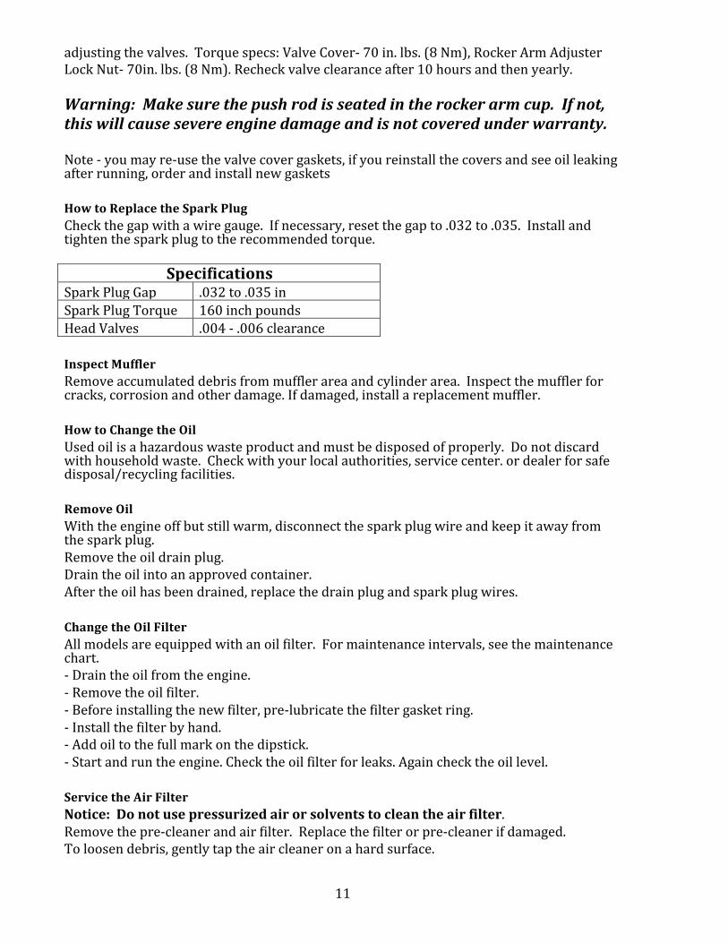
adjusting the valves. Torque specs: Valve Cover-‐ 70 in. lbs. (8 Nm), Rocker Arm Adjuster Lock Nut-‐ 70in. lbs. (8 Nm). Recheck valve clearance after 10 hours and then yearly. Warning: Make sure the push rod is seated in the rocker arm cup. If not, this will cause severe engine damage and is not covered under warranty. Note -‐ you may re-‐use the valve cover gaskets, if you reinstall the covers and see oil leaking after running, order and install new gaskets How to Replace the Spark Plug Check the gap with a wire gauge. If necessary, reset the gap to .032 to .035. Install and tighten the spark plug to the recommended torque.
Specifications Spark Plug Gap .032 to .035 in Spark Plug Torque 160 inch pounds Head Valves .004 -‐ .006 clearance Inspect Muffler Remove accumulated debris from muffler area and cylinder area. Inspect the muffler for cracks, corrosion and other damage. If damaged, install a replacement muffler. How to Change the Oil Used oil is a hazardous waste product and must be disposed of properly. Do not discard with household waste. Check with your local authorities, service center. or dealer for safe disposal/recycling facilities. Remove Oil With the engine off but still warm, disconnect the spark plug wire and keep it away from the spark plug. Remove the oil drain plug. Drain the oil into an approved container. After the oil has been drained, replace the drain plug and spark plug wires. Change the Oil Filter All models are equipped with an oil filter. For maintenance intervals, see the maintenance chart. -‐ Drain the oil from the engine. -‐ Remove the oil filter. -‐ Before installing the new filter, pre-‐lubricate the filter gasket ring. -‐ Install the filter by hand. -‐ Add oil to the full mark on the dipstick. -‐ Start and run the engine. Check the oil filter for leaks. Again check the oil level. Service the Air Filter Notice: Do not use pressurized air or solvents to clean the air filter. Remove the pre-‐cleaner and air filter. Replace the filter or pre-‐cleaner if damaged. To loosen debris, gently tap the air cleaner on a hard surface.

12
Wash the air filter and pre-‐cleaner with household detergent. Dry the filter and pre-‐cleaner. How to Clean the Air Cooling System Notice: Do not use water to clean the engine. Water could contaminate the fuel system. Use a brush or dry cloth to clean the engine. This is an air-‐cooled engine. Dirt or debris can restrict airflow and cause the engine to overheat resulting in poor performance and shortened engine life. Use a brush or dry cloth to remove debris from the intake guard, cylinder heads and muffler area. Inspect and clean the cooling fins. Loosen the two front panel screws and clean the area under the panel. How to Replace the Fuel Filter Use pliers to squeeze the tabs on the fuel filter clamps. Slide the clamps away from the filter. Carefully remove the fuel filter and properly dispose of any leaking fuel. Check the fuel line for any cracks or leaks. Replace if necessary. Replace the fuel filter with an original equipment fuel filter. Secure the fuel filter with the hose clamps. Storage -‐ Fuel System Fuel can become stale when stored over 30 days. Stale fuel causes acid and gum deposits to form in the fuel system and essential carburetor parts. To keep the fuel fresh, use a fuel treatment and stabilizer, available at most automotive stores. There is no need to drain gasoline from the engine if a fuel stabilizer is added according to instructions. Run the engine 2 minutes after adding the stabilizer to the fuel tank. If stored longer than 30 days, the cylinders should be protected with a cylinder fogging available from marine stores by injecting the fog in the cylinders through the spark plug holes. Cylinders that become corroded will loose compression and void the emissions warranty. Cover the engine from rain and snow to prevent corrosion and water from entering the exhaust outlet. If gasoline in the engine has not been treated with a stabilizer, it must be drained into an approved container. Run the engine until it stops from lack of fuel. Common Service Parts and Suggested Replacement Period Air Filter -‐ 100 Hours Ark ARK Air Prefilter Models 4400, 4400S and 5000 -‐ 100 Hours Fuel Filter -‐ 100 Hours Oil Filter -‐ 50 Hours ARK Muffler – 100 hours Spark Plug -‐ 100 Hours

13
Warning – Propeller Balance A badly worn, damaged or out-‐of-‐balance propeller can cause severe damage to the drive and engine. A bad propeller will cause significant vibration in the handle and lower skeg. Damage caused by a bad propeller is not covered under our warranty. Limited Warranty: What is covered: Mud Buddy will cover all materials and labor costs associated with repairing or replacing any factory-‐supplied part found to be in defective in material or workmanship under normal use and maintenance. Who is entitled to coverage: This limited warranty extends to the first retail purchaser or subsequent owner within the warranty period. Term of Coverage: This limited warranty is in effect for these periods from the retail sale date: One Year – Frame and Drive all Models One Year – Model 4000 and 4400 Six Months – Model 5000 Three Year – Vanguard 3600 engine Five Year or 175 Hour -‐ Model 4000, 4400 and 5000 emissions Five Year -‐ Castings Parts Only (no shipping or labor included) What is not covered: Mud Buddy will not cover recommended maintenance, adjustments, or repairs for the parts that fail or are damaged as a result of improper break in, accident, collision, abuse, misuse, neglect, vandalism, flood, wear and tear, improper or inadequate maintenance, post-‐delivery modifications or alterations, or the addition of aftermarket parts or accessories that Mud Buddy has not authorized or approved for use. Dealers are Independent businesses: Although authorized to sell and to service our shallow water outboard motors under warranty, the dealer is independent of Mud Buddy. We do not control the dealer and are not responsible for and shall not be bound by any representations or assurance made by the dealer employee or representative. NO DEALER IS AUTHERIZED TO MODIFY THIS LIMITED WARRANTY OR MAKE A WARRANTY OR CREATE ANY OBLIGATIONS ON OUR BEHALF. Some dealers have limited warranty training and you may be required to take your product to a qualified engine and/or drive warranty center. Model 44 engines must be returned to Mud Buddy for repair. Customers are responsible for all shipping costs to and from the dealer and or Mud Buddy as required to perform recommended warranty service. Obtaining Warranty Services: To obtain warranty service, you must, at your own cost, deliver your Mud Buddy to an authorized Mud Buddy Service facility during normal business hours and, if requested, by present proof that your Mud Buddy vehicle has been serviced and maintained as recommended in Periodic Maintenance Chard included in the Owner’s manual. Note it is the owner’s responsibility to maintain the Mud Buddy as recommended in the periodic maintenance Chart and to be Responsible for all associated costs. Failure to maintain the Mud Buddy as recommended my void coverage under this limited Warranty.

14
Questions about Warranty Service If you have questions, comments, or concerns about this limited Warranty or warranty service you’ve requested or received, please contact Mud Buddy Customer Service at 1-‐801-‐352-‐8011. One-‐ Year Limitation on Imitating a Claim In the event you elect to make a claim for breach of this Limited Warranty or an applicable implied warranty, you must initiate the claim within one – year after the date on which the breach occurs. A judgment based on an arbitration award may be entered by any court with jurisdiction over the parties Note: Any claim that falls within the jurisdiction of a Small Claims court bay be brought in that court, or made the subject or an arbitration proceeding under this paragraph, at the election of the consumer. Repair Costs Are your Sole and Exclusive Remedy Your sole and exclusive remedy for breach of this limited Warranty is money damages in an amount equal to the reasonable cost for material and labor necessary to repair or replace parts that should have been done under our promise to repair, but where not. Your Sole and Exclusive Remedy For breach of any applicable implied Warranty is money damages in an amount equal to the reasonable cost for material and labor necessary to correct the defect or defects upon which the finding on the breach of implied warranty is based. Incidental and Consequential damages-‐ Such as towing or transport charges, aggravation, inconvenience, Lost profits, wages or income, Loss of use, Replacement Vehicle Rental Charge, and telephone, Food , and lodging costs are not recoverable from Mud Buddy for breach of this limited warranty or and implied warranty under any circumstances, Note Some stated do not allow the exclusions of limitation of incidental or consequential damages, So the above limitation or exclusion may not apply to you. THIS WARRANTY GIVES YOU SPECIFIC LEGAL RIGHTD< AND YOU MAY ALSO HAVE OTHER RIGHTS WHICH VARY FROM STATE TO STATE. Manufacturer’s Emissions Warranty Coverage If any emission related part on your engine is defective, the part will be repaired or replaced by Briggs and Stratton and Mud Buddy. Owner’s Warranty Responsibilities As the engine owner, you are responsible for the performance of the required maintenance listed in your owner’ manual. MUD BUDDY LLC recommends that you retain all your receipts covering maintenance on your engine, but MUD BUDDY LLC cannot deny warranty solely for the lack of receipts or for your failure to ensure the performance of all scheduled maintenance.

15
As the engine owner, you should however be aware that MUD BUDDY LLC may deny warranty coverage of your marine engine or a part has failed due to abuse, neglect, improper maintenance or unapproved modifications. You are responsible for presenting your engine to an MUD BUDDY LLC Service Dealer as soon as a problem exists. The warranty repairs should be completed in a reasonable amount of time. Dealers If you have any questions regarding your warranty rights and responsibilities, you should contact a MUD BUDDY LLC Service Representative at 1-‐801-‐352-‐1455. Manufacturer Emissions Control Warranty Provisions The following are specific provisions relative to your Emissions Control Warranty Coverage. It is in addition to the manufacturer engine warranty for non-‐regulated engines found in the Operator’s Manual. 1. Warranted Emission Parts Coverage under this warranty extends only to the parts listed below (the emissions control systems parts) to the extent these parts were present on the engine. a. Fuel Metering System -‐ Cold start enrichment system (soft choke) -‐ Carburetor and internal parts -‐ Fuel pump -‐ Fuel line, fuel line fittings, clamps b. Air induction system -‐ Air cleaner -‐ Intake manifold -‐ Purge and vent line c. Ignition System -‐ Spark plug(s) and magneto ignition system d. Exhaust system -‐ Exhaust manifold e. Miscellaneous items used in the above systems -‐ Connectors and assemblies 2. Length of Coverage For a period of three years from date of original purchase, the manufacturer warrants to the initial owner and each subsequent purchaser that the engine is free from emission defects in materials and workmanship that could cause the failure of the warranty part, and that it is identical in all material respects to the engine described in the manufacturer’s application for certification. For models 4000, 4400 and 5000 the emissions warranty is 175 hours or five years. The warranty period begins on the date the engine is originally purchased.

16
The warranty on emissions-‐related parts is as follows: Any warranted part that is not scheduled for replacement as required maintenance in the owner’s manual supplied, is warranted for the warranty period stated above. If any such part fails during the period of warranty coverage, the part will be repaired or replaced by the manufacturer at no charge to the owner. Any such part repaired or replaced under the warranty will be warranted for the remaining warranty period. Any warranted part that is scheduled for replacement as required maintenance in the owner’s manual supplied, is warranted for the period to the first scheduled replacement point for that part. If the part fails prior to the first scheduled replacement, the part will be repaired or replaced by the manufacturer at no charge to the owner. Any such part repaired or replaced under the warranty will be warranted for the remainder of the warranty period prior to the first scheduled replacement point for that part. Add on or modified parts may not be used. The use of any non-‐exempted add on or modified parts by the owner will be grounds for disallowing a warranty claim. The manufacturer will not be liable to warrant failures of warranted parts caused by the use of a non exempted add on or modified part. 3. Consequential Coverage Coverage shall extend to the failure of any engine components caused by the failure of any warranted emissions part. 4. Claims and Coverage Exclusions Warranty claims shall be filed according to the provisions of the engine warranty policy. Warranty coverage does apply to failures of emission parts that are not original equipment parts or to parts that fail due to abuse, neglect, or improper maintenance as set forth in the Mud Buddy LLC engine warranty policy. No liability is accepted for warranty coverage of failures to emissions parts caused by the use of add-‐on or modified parts. 5. High Altitude Model 4000, 4400, and 5000 engines are equipped with a nonadjustable Mikuni HSR 42 carburetor. This engine is not recommended for altitude use of 4000 feet (1219 meters) or above. Operation of engine above 4000 feet will cause damage to engine and void engine warranty. Contact your dealer if you have questions. 6. Emissions Label Look for relevant emissions, date of manufacture, engine family and the durability period on your engine emissions label located on the cover side of your engine. Contact Information Mud Buddy Manufacturing [email protected] -‐ customer service 7956 South, 1530 West, Suite 100 [email protected] -‐ parts West Jordan, Utah 84088 801.352.8011 801.569.3799 fax