spln_11a_1978_(iec_pub._60-1_first_edition_1973)
30
_: Publication 00-l C(lM M ISSI(l N.fEL EN,T R (lT EG HNI OU E INT ERl,IATI(l l'I A L E t .,.r (affili6e'h ll0rganisation InJernationale deNormalisation - lS0) REC(|MMANDATI(|iI DE TA CEI III T ERNATI.(l 1,I"A L EL ECT R (l T EG HNICAL C (l M MIS S I(l II r,, (af{iliated p the International 0rganization for Standardization - lS0) I E C REC(lMMENIlATIllN Publication 60-l Premidre 6dition - First edition 1973 Techniques des essais e PremiBre partie: D6finitions el prescriptions haute tension g6n6rales relatives aux essais High-uoltage test techniques Part l: General definitions and lest requirements Droits dereproduction rdserv6s - Copyright - allrights reserved Bureau Central de laCommission Electrotechnique Internationale 1, rue deVarembd Gendve. Suisse
-
Upload
fakhri-munziar -
Category
Documents
-
view
212 -
download
0
description
Standard PLN
Transcript of spln_11a_1978_(iec_pub._60-1_first_edition_1973)

_:
Publication 00-l
C ( l M M I S S I ( l N . f E L E N , T R ( l T E G H N I O U E I N T E R l , I A T I ( l l ' I A L Et .,.r (affi l i6e'h l l0rganisation InJernationale de Normalisation - lS0)
R E C ( | M M A N D A T I ( | i I D E T A C E I
I I I T E R N AT I . ( l 1 , I "A L E L E C T R ( l T E G H N ICA L C ( l M M IS S I ( l I Ir, , (af{ i l iated p the International 0rganization for Standardization - lS0)
I E C R E C ( l M M E N I l A T I l l N
Publication 60-lPremidre 6dit ion - First edit ion
1 9 7 3
Techniques des essais ePremiBre partie: D6finitions el prescriptions
haute tensiong6n6rales relatives aux essais
High-uoltage test techniquesPart l: General definitions and lest requirements
Droits de reproduction rdserv6s - Copyright - all r ights reserved
Bureau Central de la Commission Electrotechnique Internat ionale
1, rue de Varembd
Gendve. Suisse

Rdvision de la pr6sente publication
Le contenu technique des publications de la CEI estconstamment revu par la Commission afin d'assurer qu'i lrefldte bien l '6tat actuel de la technique.
Les renseignements relatifs i ce travail de rdvision, itl'€tablissement des dditions r6vis6es et aux mises ir jourpeuvent €tre obtenus auprds des Comitds nationaux de laCEI et en consultant les documents ci-oessous :
O Bulletin de Ia CEI
Publid trimestriellement
O Rapport d'activit6 de la CEI
Publi6 annuellement
O Catalogue des publications de la CEI
Publi6 annuellement
Terminologie utilis6e dans Ia pr6sente publication
Seuls sont d€finis ici les termes spdciaux se rapportantd Ia pr6sente publication.
En ce qui concerne la terminologie g6n6rale, le lecteurse reportera ir la Publication 50 de la CEI: VocabulaireElectrotechnique International (V.E.I.), eui est dtabliesous forme de chapitres sdpar6s traitant chacun d'un sujetd6fini, I ' index g€ndral 6tant publi6 s6par6ment. Des ddtailscomplets sur le V.E.I. peuvent Otre obtenus sur demande.
Symboles graphiques et litt6raux
Seuls les symboles graphiques et l itt€raux spdciaux sontinclus dans la prdsente publication.
Le recueil complet des symboles graphiques approuv6spar la CEI fa i t I 'objet de la Publ icat ion 117 de la CEI.
Les symboles littdraux et autres signes approuv6s parIa CEI font I 'objet de la Publication 27 dela CEI.
Autres publications de Ia C E I 6tablies par lem6me Comit6 d'Etudes
L'attention du lecteur est attirde sur la page 3 de lacouverture, qui €numdre les autres publications de la C E Ipr6par6es par le Comit6 d'Etudes qui a dtabli la pr6sentepubl icat ion.
Revision of this publication
The technical content of IEC publications is keptunder constant review by the IEC, thus ensuring that thecontent reflects current technology.
Information on the work of revision, the issue ofrevised editions and amendment sheets may be obtainedfrom IEC National Committees and from the followinsIEC sources:
O IEC Bulletin
Published quarterly
O Report on IEC Activities
Published yearly
O Catalogue of IEC Publications
Published yearly
Terminology used in this publication
Only special terms required for the purpose of thispublication are defined herein.
For general terminology, readers are referred to I E CPublication 50: International Electrotechnical Vocabulary(I.E.V.), which is issued in the form of separate chapterseach dealing with a specific field, the General Indexbeing published as a separate booklet. Full details of theI .E.V. wi l l be suppl ied on request .
Graphical and letter symbols
Only special graphical and letter symbols are includedin this publication.
The complete series of graphical symbols approved bythe IEC i s g i ven in IEC Pub l i ca t i on t17 .
Letter symbols and other signs approved by the IECare contained in IEC Publ icat ion 27.
Other IEC publications prepared by the sameTechnical Committee
The attention of readers is drawn to the inside of theback col 'er , which l is ts other I E C publ icat ions issuedby the Technical Committee v,,hich has prepared thepresent publication.
IF

r
:
:
C.D.U. /U.D.G. : [621.317.333.6.024/ .025.027.3+621.317.333.821.83] .001.11.001,2.001.4
c0M M I ss | 0 ],t E I r cT R 0T E c H N I 0 U E I N T E R NATt 0 1{ A L E(affi l i6e d l '0rganisation Internationale de Normalisation - lS0)
R E C ( l M M A N O A T I ( } I , I l I E I . A C E I
| 1,1 T E R NATI 0 N A L E L E c T B 0T Ec H N I GA L c 0 M M I ss I 0 ttl(aff i l iated to the International 0rganization for Standardization - lS0)
I E C R E C t l M M E N I l A T I ( l N
Publication 60-lPremidre 6dit ion - First edit ion
1 9 7 3
Techniques des e$sais ePremiire partie: D6finitions et prescriptions
haute tensiong6n6rales relalives aux essais
High-uoltage test techniquesPart l: General definitions and test requirements
PER PLTSTA KA ANpu$nT ?rl?Euol[tr rtElt^H rfusTifxAff
No. Agendr
Trng6al
Droits de reproduction 16serv6s - Copyright - al l r ights reserved
Aucune part ie ds cette publ icat ion ne peut 0tre reproduite ni ut i l isde sous No part of this publ icat ion may be reproduced or ut i l ized in anyquelque forme que ce soit et par aucun procEd6, 6lectronique ou m€ca- form or by any means, electronic or mechanical, including photocopyingnique, y compris la photocopie et les microf i lms, sans I 'accord dcri t de l '6diteur. and microl i lm, without permission in writ ing from the publisher.
Bureau Central de la Commission Electrotechnique lnternationale1, rue de Varemb6
Gendve, Suisse
iil,t, ?,. A7.-

FonEwoRo
PnE,rA,ce
Clause1. Scope
2. Object
6. General arrangement of the test object
7. Dry tests
8. Wet tests8.1 Revised wet test procedure
8.2 Conventional procedures for wet tests
9. Artif icial pollution tests
9.1 Preparation of test object
9.2 Test procedures
9.3 Degree of pollution .
10. Atmospheric conditions .. .
10.1 Atmospheric correction factors .
10.2 Standard reference atmosphere .
10.3 Air density and humidity correction
10.4 Measurement of humiditv
- 3 -
CONTENTS
SrcrroN ONe - GrNrnar
with alternating voltage
[actors
Page5
5
7
7
7
7
9
9
99
9
9
1 1
1 1
1 l
1 l
l l
1 l1 l
1 l
1 1l l
J .
4 .
SEcrroN Two - GENBRaT DEFINITIoNs
Impulses
3.1 Lightning and switching impulses .
Characteristics related to disruptive discharge and test voltages .
4.1 Disruptive discharge
4.2 Value of test voltage
4.3 Disruptive discharge voltage
4.4 Prospective characteristics of a test voltage
4.5 Disruptive discharge probability p
4.6 Withstand probability
4.7 Rated withstand voltage
4.8 Assured disruptive discharge voltage
4.9 507o disruptive discharge voltage .
4.10 xo/o disruptive discharge voltage
5. Classification of insulation
5.1 External insulation
5.2 Internal insulation
5.3 Self-restoring insulation
5.4 Non-self-restoring insulation .
SscrroN TlrRrs - GrNrnaL REeUTREMENTS RELATTNG To rEsr pRocEDURE AND TEsr oBJEcrs
l 3
1 3
l 3
1 3
1 5
l 7t 7
t 9
2 l
2 l2 I
2 l
2323
ApprNorx A - Production of saline fog
ApprNorx B - Pre-deposition of pollution, coating and wetting procedure
AppeNolx C - Measurement of the degree of pollution
FrcuRrs
27
29
33
34

l )
INTERNATIONAL
- ) -
ELECTROTECHNICAL COMMISSION
HIGH.VOLTAGE TEST TECHNIQUES
Part L: General definitions and test requirements
FOREWORD
The formal decisions or agreements of the IEC on technical matters, prepared by Technical Committees on which all the
National Committees having a special interest therein are represented, express, as nearly as possible, an international
consensus of opinion on the subjects dealt with.
They have the form of recommendations for international use and they are accepted by the National Committees in that
sense.
In order to promote international unification, the IEC expresses the wish that all National Committees should adopt
the text of the IEC recommendation for their national rules in so far as national conditions willpermit. Any divergence
between the IEC recommendations and the corresponding national rules should, as far as possible, be clearly
indicated in the latter.
PREFACE
This recommendation has been prepared by IEC Technical Committee No. 42, High-Voltage Testing
Techniques.
It constitutes a revision of that part of IEC Publication 60, 1962, which deals with general test speci-
fications, more specifically Sections One, Two and Three. Another recommendation, IEC Publication 60-2(Third edition): Test Procedures, covers Sections Four, Five, Six and Seven. A final document: Approved
Measuring Devices, covering Section Eight and the Appendix of IEC Publication 60, 1962, is under
preparation together with an Application Guide.
During a meeting in Bucharest in 1962, a general discussion was held concerning what modifications
and addendums were foreseen for the IEC Publication 60, then under printing. Subsequent drafts were
circulated and discussed in Aix-les-Bains in 1964, in Tokyo in 1965 and in London in 1968. As a result
of this latter meeting, a final draft, document 42(Central Office)14, was submitted to the National Commit-
tees for approval under the Six Months'Rule in June 1910. Due to negative votes from France and
the U.S.S.R., & revised draft, documents 42(Central Office)2| and42(Central Office)21A, was submitted to
the National Committees for approval under the Two Months' Procedure in'March and April 1972.
By these successive procedures, the negative votes were eliminated.
The following countries voted explicitly in favour of publication:
I
AustraliaAustriaBelgiumBrazllCanadaCzechoslovakiaDenmarkFinlandFrance
GermanyHungaryIsraelItalyJapan
NetherlandsNorwayPolandPortugalRomaniaSouth Africa (Republic of)SwedenSwitzerlandTurkeyUnion of Soviet
Socialist Republics
United KingdomUnited States of America
Yugoslavia

- 7 -
HIGH-VOLTAGE TEST TECHNIQUES
Part L: General definitions and test requirements
SECTION ONE - GENERAL
l. Scope
This recommendation is applicable to:- dielectric tests with direct voltage;- dielectric tests with alternating voltage;- dielectric tests with impulse voltage;- tests with impulse current.
2. Object
The object of this recommendation is:- to define terms of general applicability;- to present general requirements regarding test objects and test procedures.
Definitions and requirements concerning specific types of tests are given in I EC Publication 60'2,
High Voltage Test Techniques, Part 2: Test Procedures, and those concerning approved measuring
devices and checking methods will be given in the future IEC Publication 60-3 and an Application
Guide (revision of Section Eight and of the Appendix of IEC Publication 60, 1962).
SECTION TWO - GENERAL DEFINITIONS
3. ImpulSes
An impulse is an intentionally applied aperiodic transient voltage or current which usually rises
rapidly to a peak value and then falls more slowly to zero. Such an impulse is in general well
represented by the sum of two exponentials.
For special purposes, impulses having approximately linearly rising fronts or of oscillating or
approximately rectangular form are used.
The term "impulse" is to be distinguished from the term "surge" which refers to transients
occuring in electrical equipment or networks in service.
3.1 Lightning and switching impulses
A distinction is made between lightning impulses and switching impulses on the basis of the
duration of the front. Impulses with front durations from less than one up to a few tens of micro-
seconds are in general considered as lightning impulses and those having front durations of some
tens up to thousands of microseconds as switching impulses. Generally, switching impulses are also
characterized by considerably longer total durations than those of lightning impulses.
Note. - If required, a more rigorous distinction may be made by the relevant Technical Committee. Such a dis-
tinction is made in IEC Publication 99-1, Lightning Arresters, Part 1: Non-linear Resistor Type Arresters
for a.c. Systems, and is based on a virtual front time of 30 ps.

-1.
4 . 1
4.2
4 . 3
- 9 -
Characteristics related to disruptive discharge and test voltages
Disruptive discharge
In this recommendation, the term "disruptive discharge" relates to phenomena associated with
the failure of insulation under electrical stress, in which the discharge completely bridges the
insulation under test, reducing the voltage between the electrodes to zero or nearly to zero. It
applies to electrical breakdown in solid, liquid and gaseous dielectrics and to combinations of these.
Discharges between intermediate electrodes or conductors, as well as momentary flashovers
(snap-overs), may occur with alternating voltage without permanent reduction of the test voltage
to zero. The occurrence of snap-overs may depend on the characteristics of the test circuit. Whether
such an occurrence constitutes a failure or not, and whether it requires a repetition of the test,
should be decided by the relevant Technical Committee.
Discharges which do not completely bridge the insulation between electrodes are termed "partial
discharges" and are dealt with in IEC Publication 270, Partial Discharge Measurements.
The term "sparkover" is used when a disruptive discharge occurs in a gaseous or liquid dielectric.
The term "flashover" is used when a disruptive discharge occurs over the surface of a dielectric
in a gaseous or l iquid medium.
The term o'puncture" is used when a disruptive discharge occurs through a solid dielectric.
A disruptive discharge in a solid dielectric produces permanent loss of dielectric strength; in a
liquid or gaseous dielectric, the loss may be only temporary.
Value of test voltage
The value of the test voltage is the voltage value, defined according to IEC Publication 60-2,
which is to be applied in a test.
Disruptive dis char ge voltage
For direct voltage, alternating voltage and impulse voltages chopped at or after the crest, the
disruptive discharge voltage is the value of the test voltage causing disruptive discharge. For defi-
nit ion of this value. see IEC Publication 60-2.
For impulse voltages chopped on the front, the disruptive discharge voltage is defined as the
voltage at the instant when disruptive discharge occurs (see also Sub-clause 4.4).
Disrdptive discharge voltages are subject to random variations and, usually, a number of obser-
vations must be made in order to obtain a statistically significantvalue of the voltage. The test
procedures, described in IEC Publication 60-2, are generally based on statistical considerations.
The same document also gives information on the statistical evaluation of test results.
Prospective charocteristics of a test voltage
The prospective characteristics of a test voltage causing disruptive discharge are the charac-
teristics which would have been obtained if no disruptive discharge had occurred. When a prospective
characteristic is referred to, this should always be stated.
Disruptive discharge probability p
The disruptive discharge probability is the probability that the application of a certain prospective
voltage value of a given shape will cause disruptive discharge.
4.4
.1.5

1 1 -
4.6 Withstand probability
The withstand probability is the probability that the test object will withstand one application
of a certain prospective voltage value and shape. If the disruptive discharge probability is p, the
withstand probability is (l - p).
4.7 Rated withstand voltage
The rated withstand voltage of a test object is a specified voltage value which characterizes the
insulation of the object with regard to a withstand test.
4.8 Assured disruptive discharge roltage
An assured disruptive discharge voltage is a specified voltage value which characterizes the
insulation of the object with regard to a disruptive discharge test.
4.9 50o/o disruptive discharge voltage
The 50% disruptive discharge voltage is the prospective voltage value which has a 50% prob-
ability of producing a disruptive discharge.
4.10 xo/o disruptive discharge voltage
The xoh disruptive discharge voltage is the prospective voltage value which has xo/o probability
of producing a disruptive discharge.
5. Classification of insulation
5.1 External insulation
External insulation is the air insulation and the exposed surfaces of solid insulation of equipment,
which are subject both to dielectric stresses and to the effects of atmospheric and other external
conditions such as pollution, humidity, vermin, etc.
5.2 Internal insulation
Internal insulation comprises the internal solid, liquid or gaseous elements of the insulation of
equipment, which are protected from the effects of atmospheric and other external conditions such
as pollution, humidity, vermin, etc.
5.3 Self-restoring insulation
Self-restoring insulation is insulation which completely recovers its insulating properties after
a disruptive discharge caused by the application of a test voltage. In insulation of this kind,
disruptive discharges generally, but not necessarily, occur in the external part of the insulation.
5.4 Non-self-restoringinsulation
Non-self-restoring insulation is insulation which loses its insulating properties, or does not
recover them completely, after a disruptive discharge caused by the application of a test voltage.
In insulation of this kind, disruptive discharges generally, but not necessarily, occur in the internal
part of the insulation.

- 1 3 -
SECTION THREE - GENERAL REQUIREMENTS RELATING
TO TEST PROCEDURE AND TEST OBJECTS
6. General arrangement of the test object
At the time of a test, the test object shall be complete in all essential details, and it should have
been processed in the normal manner for similar equipment (for instance by vacuum impregnation
and thermal treatment).
The disruptive discharge characteristics of a test object may be affected by its general arrangement,
for example by its clearance from external structures, its height above ground level, the arrangement
of the high voltage lead. A clearance to external structures equal to 1.5 times the length of the
shortest possible discharge path on the test object usually makes such proximity effects insignificant.
Larger clearances may be required in the cases of switching impulse tests or in tests at very high
voltage, to avoid sparkovers to extraneous structures. In wet tests or pollution tests, or wherever
the voltage distri.bution in the test object is sufficiently independent of external influences, smaller
clearances may be acceptable provided that flashovers do not occur to extraneous structures.
7 . Dry tests
The test object should be dry and clean. If not otherwise specified by the relevant Technical
Committee, the test should be made at ambient temperature and the procedure for voltage appli-
cation should be as specified in IEC Publication 60-2.
8. Wet tests
The wet test method, described in Sub-clause 8.1, is intended to simulate the effect of natural
rain on external insulation and is a revision of earlier test methods. It is recommended for tests
with all types of test voltages, and on all types of apparatus, but see below.
Two earlier test methods, not intended to simulate natural rain, are described in Sub-clause 8.2.
These have been in use for many years for tests with alternating voltage on apparatus up to about
400 kV system voltage and many test data exist obtained by these methods. Their use is re-
commended only when direct comparison with such data is required.
Revised wet test procedure
The test object should be sprayed with water of prescribed resistivity, falling on it as droplets
and directed so that the vertical and horizontal components of the spray intensity are approxi-
mately equal. These intensities are measured with a divided collecting vessel having openings
of 100 cm2 to 750 cmz, one horizontal and one vertical, the vertical opening facing the spray.
Another less accurate practice is to measure only the vertical component and to judge by eye that
the spray is falling at an angle of approximately 45'.
The collecting vessel should be placed close to the test object, but avoiding the collection of
drops or splashes from it. During the measuring period, it should be moved slowly over a sufficient
area to averase out the effect of non-uniformities of the spray from individual nozzles.
8 . 1

_ 1 5 _
In the case of test objects with a height exceeding one metre, such measurements should be made
near the top, centre and bottom of the object. A similar procedure should be used for test objects
with large horizontal dimensions.
The spray apparatus must be adjusted to produce, within the specified tolerances, precipitation
conditions at the test object given in Table I. Any type and arrangement of nozzles meeting the
requirements given in Table I may be used. Examples of several nozzles which have been found
satisfactory in practice are shown in Figures la and lb,page34, and Figure lc,page 35, together
with typical performance data for each type. Greater spray distances may be obtained if the nozzles
are directed upward at an angle of about 15"-25' to the horizontal. Note that if the water
pressure is increased above the recommended limits, the water jets may break up prematurely and
cause an unsatisfactory spray at the test object.
Tnern I
Precipitation conditions (revised test procedure )
Average precipitation rate for all measurements:
- vertical component
- horizontal component
Limits for any individual measurements and for each
component
Temperature of collected water
Resistivity of collected water corrected to 20 'C (see note
(For correction of water resistivity to 20 oC, see Figure 2,
mm/min
mm/min
mm/min
"c
below) Om
page 37)
1 . 0 t o 1 . 5
1 . 0 t o 1 . 5
0 .5 t o 2 .0
Ambient temperature + 15
100 + 15
8 .2
Note. - For switching impulses, if the prescribed water resistivity cannot be obtained, a lower value may be used
but the actual value must be stated in the test report.
The test object should be pre-wetted initially for at least l5 min under the above specified con-
ditions and these conditions should remain within the specified tolerances throughout the test. The
pre-wetting time may include the time needed for adjustment of the spray and may be reduced
if special means are used to ensure effective wetting or when repeat tests are made after short
intervals.
Unless otherwise specifled by the relevant Technical Committee, the test procedure for wet
tests should be the same as that specified in IEC Publication 60-2 for the corresponding dry tests.
In general, for all alternating and direct voltage wet withstand tests, it is recommended that one
flashover should be permitted provided that in a repeat test no further flashover occurs.
Cont,entional procedures for wet tests with alternating voltage
For alternating voltage tests, two other procedures ate also in use, details of which are given
in Table II. They differ from the revised procedure, Sub-clause 8.1, primarily in that the precipi-
tation rates are higher and that the minimum pre-wetting time is only one minute.
Only the vertical component of the spray is specified; determination of the horizontal component
is replaced by a visual estimate of the spray angle at the test object which should be approxi-
mately 45'.

-
i'
_ 1 7 _
TlsrE II
Precipitation conditions (con't,entional procedures ) for wet tests with alternating voltage
EuropeanpracticeCharacteristics
Average precipitation rate for each measurement
- vertical component
Limits for any individual measurement
Temperature of collected water
Resistivity of collected water corrected to 20 'C
(For correction of water resistivity to 20 "C, see Figure 2,
Type of nozzle
Duration of wet withstand test
mm/min
mm/min
O C
Clm
page 37)
3 . : 0 '3
3 + 0 .75
Ambienttemperature + 15
100 + 10
As shown inFigures la and lb,
page 34, andFigure 1c, page 35
60
Practicein U .S .A .
5 + 0 . 5
5 + 1 . 2 5
Ambienttemperature +
178 + 27
As shown inFigure ld, page 36
9. Artificial pollution tests
Artificial pollution tests are intended to provide information on the behaviour of external insu-
lation under conditions representative of pollution in service, although they do not necessarily
simulate any particular service conditions.
The following specifications give some general guidance on artificial pollution testing. It is left
to the relevant Technical Committee to introduce variations or to give more specific requirements
for particular classes of apparatus. Such specific information will be given in a future IEC
Report, Artificial Pollution Tests for h.v. Insulators to be Used on a.c. Systems, prepared by
IEC Technical Committee No. 36. It will be published only in the form of an IEC Report, since
it was considered necessary to acquire more experience by comparing test results with those
obtained in service.
The effects of washing of insulators in service by natural rain is not taken into consideration
in any of the specified procedures.
Preparation of test object
Before testing for the first time, the metal parts of the test object, and any cement joints, may
be painted with salt-water resistant paint to ensure that corrosion products will not contaminate
the insulating surfaces during a test.
The test object should then be carefully cleaned by washing with tap water to which trisodium
phosphate (NasPOr) has been added and rinsed with clean tap water. It shall not subsequently
be touched by hand. Usually the insulating surfaces can be considered suffi.ciently clean and free
of grease or other contaminating material if large continuous wet areas are observed during
wetting.
It is left to the relevant Technical Committee to decide whether the test object should be tested
in a vertical, horizontal or inclined position.
9 . 1

t 9 -
9.2 Test procedures
Artificial pollution tests involve application of the pollution and the simultaneous or subsequentapplication of voltage. Generally, only methods in which the test voltage is held constant for atleast several minutes are recommended. Other methods in which the voltage is raised graduallyto flashover are not proposed for standardizatron but may be used for special purposes.
The pollution test may be made either to determine the maximum degree of pollution of the testobject which allows a given test voltage to be withstood, or to determine the withstand voltagefor a specified degree of pollution. For the purpose of comparing the results of several tests, orthe performance of several test objects, the former procedure is preferable. Whichever test procedureis adopted, the number of measurements should be sufficient to obtain consistent average values,taking into account the statistical nature of the phenomenon.
The pollution tests fall into two categories, the saline fog method and the pre-deposited pollutionmethod.
a) The saline fog method
The test object is placed in a special chamber which can be filled by a saline fog. An exampleof a method for producing the fog is described in Appendix A. The ambient temperature in thechamber at the start of the test should not be less than 5 oC, nor greater than 30'C and thetest object shall be in thermal equilibrium with the ambient temperature.
The test object is thoroughly wetted with clean tap water. The saline fog system, supplied bywater of the prescribed salinity, is started when the test object is stili wet and, simultaneously,the voltage is applied to the test object, raised rapidly to the specified value and kept constantduring the specified time, usually one hour, or until flashover occurs. Usually, this procedureis repeated several times. Before each procedure the test object is thoroughly washed with cleantap water to remove any trace of salt.
If the test is intended to determine the maximum degree of salinity for a specified withstandvoltage, the whole procedure must be repeated using various different salinities.
Pre-conditioning of the test object by a number of f lashovers during the application of pollutionis recommended before the real test begins. Even this pre-conditioning should be followed bya washing.
b ) The pre-deposited pollution method
The test object is coated with a reasonably uniform layer of a conductive suspension, and maythen be permitted to dry. The test object is then usually placed in a special test chamber. Theambient temperature in the chamber at the start of the test should not be less than 5 oC norgreater than 30'C and the test object should be in thermal equil ibrium with the ambient. Thelayer is wetted until its surface resistivity reaches the minimum value, the voltage is appliedimmediately thereafter (but see note overleaf), raised to the specified value and kept constantduring the specified time, usually 15 min or until flashover occurs. Examples of suitablecoating and wetting procedures are given in Appendix B and of the measurement of thesurface resistivity in Appendix C.
The procedure above may be repeated several times; before each time, the test object shouldbe allowed to dry and should then be re-wetted. If, however, the surface resistivity has changedsignificantly, the test object should be washed and the coating procedure repeated.

9 . 3
- 2 1 -
When the test is intended to determine the maximum degree of pollution for a specified withstand
voltage, the coating, wetting and test procedures must be repeated using various different
suspension resistivities.
As a variation of the above, methods are in use in which the coating material retains the moisture
during the period of test and thus does not necessitate a subsequent wetting (see Appendix B).
Note, - Pre-deposited pollution methods are also in use in which constant voltage is applied to the test object
before the wetting.
Degree of pollution
The degree of pollution of a test object can be specified either by the surface resistivity or by
the amount of conductive matter per cm2 of the insulating surface. Information about these
methods is given in Appendix C.
10. Atmospheric conditions
10.1 Atmospheric correctionfactors
The disruptive discharge of external insulation depends upon the prevailing atmospheric con-
ditions. Usually, the flashover voltage for a given path in air is increased by an increase in either
air density or humidity. However, when the relative humidity exceeds about 80o ,the flashover volt-
age becomes irregular, especially when the flashover occurs across an insulating surface.
By applying correction factors, a measured flashover voltage may be converted to the value
which would have been obtained under the reference atmospheric conditions. Conversely,
a test voltage specified for the reference conditions can be converted into the equivalent
value under the prevailing test conditions.
There are two correction factors:- the air density correction factor fr6 (see Sub-clause 10.3);- the humidity correction factor kh (see Sub-clause 10.3).
The disruptive discharge voltage is proportional to kalka.
If not otherwise specified by the relevant Technical Committee, the voltage to be applied during
a withstand test on external insulation is determined by multiplying the specified withstand voltage
by k6lky,. Similarly, measured disruptive discharge voltages are corrected to those applicable for
standard reference atmosphere by dividing by kalk1,.
It is left to the relevant Technical Committee to decide whether or not corrections have to be
applied to the voltage values in those cases where both external and internal insulations are involved.
The test report should always contain the actual atmospheric conditions during the test and it must
be indicated whether corrections have been applied or not.
I0.2 Standard reference atmosphere
The standard reference atmosphere is:
Temperature /6 : 20 "C
Pressure bo : 1 0l3x 105 N/m' (l 013 mbar)
Humidity lto : 11 g water per m3.
Note. - A pressure of 1013 mbar corresponds to a height of 760 mm in a mercury barometer of 0'C. If the height
of the barometer is If mm of mercury and the temperature is / oC, the atmospheric pressure in millibar is:
u : ! : # (1 -1 .8x 1o -4x r )

- 2 3 -
10.3 Air density and humidity correction factors
If the atmospheric pressure 6 is expressed
the air density correction factor becomes:
in mill ibars and the temperature r in degrees Celsius,
/ h \ r n , 2 7 3 i l o \ "o " : ( 4 / t ( z z r + t l
Sirnilarly, the humidity correction factor is:ky , : (k ) *
The constant k is given in Figure 3, page 38, as a function of absolute humidity, curve a or b
being applicable according to the type of voltage. The exponents ffi, o and w depend on the type
and polarity of the voltage and on the flashover distance d as given in Table III and Figure 4,
page 38. Lacking more precise information, m and n are assumed to be equal.
The symbols of Table III are:
Io Gaps giving an essentially uniform field.?I
II
Iv7v777)
Rod-rod gaps and suspension insulators; that is, electrodes giving a non-uniform field'
but with essentially symmetrical voltage distribution.
Rod plane gaps and test objects with similar cl-raracteristics such as support insulators;
that is, electrodes giving a non-uniform field with a pronounced asymrnetrical voltage
distribution.
For any electrode arrangement not falling into one of the above classes, only the air density
correction factor, using exponentS rrr:1l:1, and no humidity correction, should be applied.
No humidity correction should be applied for wet tests or for tests under artificial pollution.
The question of density correction during such tests is under consideration,
Note. - In Table III and Figures 3 and 4, a simplification of the existing information is given. The available
experimental data fromdifferent sources always show large dispersionsand are often conflicting; moreover
relevant information for direct voltages and for switching impulses is scarce. The correctness of using equal
exponents m and n, and of their numerical values as given, is therefore uncertain'
10.4 Measurement of furmidity
The measurement of humidity is usually made by means of a hygrometer consisting of two
ventilated accurate thermometers, one being dry, the other wetted. The absolute humidity as a
function of the two thermometer readings is determined by Figure 5, page 39, which also permits
a determination of the relative humidity. It is important to provide adequate air flow, to reach
steady-state values of the readings and to read the thermometers carefully, in order to avoid
excessive errors in the determination of humidity.
Other methods for the determination of the humidity are available and may be used if it can be
demonstrated that they give sufficient accuraL:y.

- 2 5 -
Tenlr I I I
Application of atmospheric correction factors
Air densitycorrection
Polar i ty Exponentsm a n d n
(see note below)
Humidity correction
Typeof test voltage
Electrodeform Factor
I .
Exponent
Directvoltage
Alternatingvoltage
Switchingimpulse vol tage
1 . 0See Figure 3,
page 38(cr.rrve b)
See Figure 3(curve a)
See Figure 3(curve b)
See Figure 4
1 . 0
1 . 0
1 . 0
0
I?;I
I
I,vmD>
See Figure 4
t?
1 . 0
1 . 0
_T
-LI
See Figure 4
0 { <
Iv7v77n
See Figure 4
0 *
t?
See Figure 4,page 38
See Figure 4
Lightningimpulse voltage
See Figure 3(curve b)
1 . 0
0 . 8
I7Z77VZ
See Figure 4
0 *
See Figure 4
0 *
* Very litt le information is available, At present no correction is recommended.

a 1
APPENDIX A
PRODUCTION OF SALINE FOG
In this appendix' details are given as an example of one way of producing saline fog for artif icial pollutiontests made by the saline fog method.
A.1 Preparation of salt solution
The salt solution should be made up to the required salinity from sodium chloride (NaCl) ofcommercial purity and ordinary tap water. The concentration should be within + 5% of one oft h e f o l l o w i n g v a l u e s : 2 . 5 g , 3 . 5 g , 5 g , 7 g , l 0 g , 1 4 g , 2 0 g , 2 g g , 4 0 g , 5 6 g , g 0 g , r r 2 g , 1 6 0 g o r224 g per l i tre of solution.
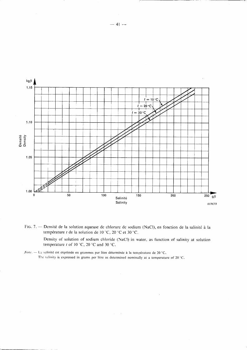
The concentration may be determined by measuring either the resistivity or the density of thesalt solution. Figures 6 and 7, pages 40 and 41, give the values of the resistivity and the densityrespectively as functions of the salt concentration at 10 'C, 20 "C and 30 "C. (See Figu re 2, page 37 ,for a larger range of variation of resistivity with temperature.) The measurement of density forconcentrations of 20 gll ot less is not recommended however, because for this measurement, avery high degree of accuracy is necessary to determine the concentration within the specifiedtolerance.
4.2 Details of spraying system
The fog is produced in a test chamber by means of a number of jets. One type in cornmon useis shown in Figure 8, page 42, and is described in detail below. Each jet has two nozzles, one actingas an air outlet and the other as an outlet for the salt solution. The compressed air thus flows acrossthe solution nozzle and produces a fine mist of the solution.
The air nozzles should be provided with filtered, oil-free air at 7 bars above the atmosphericpressure, with a tolerance of - 4oh.
The solution nozzles should be supplied with the specified salt solution at a pressure adjusted sothat the flow of the solution through each nozzle, with no air passing through the air nozzle, is0.5 l/min + l0% for the period of the test; the tolerance on the total f low to all spray jets is + 5%of the nominal value. Consequently, the solution pressure must also be kept constant throughouta test.
The jets are mounted 0.6 m apart in two straight rows, parallel to the centre line of the test object(one on each side), each row being about 3 m from it and in the same plane, with the jets in eachrow directed towards one another. Each row should extend at least 0.6 m beyond the ends of theinsulating section of the test object; the latter is mounted vertically, horizontally or inclined asprescribed by the relevant Technical Committee, but should be so piaced that the lowest jet is atleast 0.6 m above the floor.
Notes 1- -h has been demonstrated that the distance of each row of jets f rom the axis ofinfluences the measured test results. However, for variations up to , 30 cmabove, this effect is not appreciable.
the test object significantlyfrom the distance specified
2' -The technique which is described above has been used satisfactorily forinsulators and similar objects withtest voltages up to about 600 kV r.m.s. However, for large test objects and for higher voltages, modifi-cat ions toth issystemmay be needed. Inpart icular , i t maybe necessary to use morethantworows of jetsand the clearance distances may have to be increased. In such cases, a measLlrement of the degree of thepollution of the test object is recommended (see Appendix C).

- 2 9 -
APPENDIX B
PRE-DEPOSITION OF POLLUTION, COATING AND WETTING PROCEDURE
In this appendix, details are given by way of some examples of the coating and wetting procedure to be
used for the pre-deposited pollution method.
B.l Preparation of coating material
The coating material should be prepared as a suspension in water having the following composition:
100 g diatomaceous earth (Diatomite),
10 g silicon dioxide (SiOz), particle size 2 pm-20 pm (for example Aerosil),1 000 g water (ordinary tap water may be used).
Sodium chloride (NaCl) added to give required resistivity.
Suspensions of other composition may be used, if they give the required effects. In such cases,the deposit on the surface of the test object should absorb about the same amount of water as whenthe above suspension is used.
To obtain comparable test results, the measured resistivity of the suspension, when corrected tothe equivalent value at 20 "C (see Figure 2, page 37), should be within + 15% of one of the values p26given in the following table.
Teer-e B.I
Suspension resistivity p2s
Approximate equivalent surface resistivity pr2s
(see Appendix C)
0 .83 1 . 7
---------:-
50 x 103
3 . 3
100 x 103
6 . 7
200 x 103O 25 x 103
8.2 Solid coating and wetting procedure
The suspension is sprayed on to the clean surface of the test object (see Sub-clause 9.1) usingone or more spray nozzles, which may be conventional spray guns of the type used for paintingpurposes. The resulting layer should be uniformly distributed as far as possible over the whole of theinsulating surface of the test object.
It is permissible for the coating to dry out before starting the test; hence it may be applied in anyconvenient place and, if necessary, well in advance of the time of testing.
The coated test object is set up when required in the high-voltage testing area. Its whole surfaceshould then be uniformly wetted by means of a fine mist or fog, until minimum surface resistivityis obtained (usually in about 15 min - 20 min). This may be done using any convenient source ofsteam (avoiding temperature gradients of the.test object) or any form of fine mist generator. Thesurface resistivity, measured and corrected to 20'C according to Appendix C, should be approxi-mately equal to the appropriate value pszo given in Table B.I. An example of a suitable fog jet is shownin Figure 9, page 43.

- 3 1 -
During the wetting, it is important that no dripping from the edges of the insulator
The wetting is continued during the period of voltage application.
precautions should be taken to ensure that neither the materials nor the processes
introduce a health hazatd for personnel.
takes place.
used should
B.3 Flow-on method
A variation of the above method, the "flow-on method", which does not require a fog spray has
been used successfully. with this method, a suspension is used, the composition of which is such
that it retains an effectively constant resistivity for periods of l5 min - 30 min without the need to
rewet the deposited Pollution.
The following composition is recommended:
20 g pyrogenic silica (SiO2),
1 g photograPhic wetting agent,
1 000 g ordinary taq water.
Sodium chloride is added to obtain the required resistivity as chosen from the list of values given
in Table B.I .
A coating of this material is applied a short time before the starting of the test.
The coating of the test object can be accomplished by means of small cylindrical tubes the ends
of which have been pinched to obtain an approximately elliptical cross-section with internal dimen-
sions of 3 mm x 6 mm. A number of these tubes is regularly spaced on a circular ring and directed
towards the centre. The polluting solution is forced through these tubes by a pump at a suitable
pressure.
The ring and the outlets are so designed that the assembly can be passed slowly and progressively
over the insulator to be coated, the axis of the insulator being approximately at the centre of the
ring. The outlets are directed at an angle to obtain a swirling movement of the suspension and thus
provide a complete coating of the insulating surfaces. The coating procedure is carried out until
the deposited suspension is on the point of dripping off. When the coating has been completed, a
sufficient time (about 5 min) is allowed for any dripping to cease, and for the coating to stabilize.
The voltage is then applied and raised rapidly to the specified test level. It is then maintained at
this value until a flashover occurs or until any discharge activity ceases, thus indicating that no
flashover will occur.

- 3 3 -
APPENDIX C
MEASUREMENT OF THE DEGREE OF POLLUTION
The degree of pollution of the surface of the test object can be specified by one or more of the following
characteristics, see C.l and C.2 below.
C.l The surface resistivity of the insulating surface
To determine the surface resistivity of an insulating surface, the leakage resistance R1 is measured
between two bare electrodes of the test object. From this resistance, the surface resistivity is
calculated using a form factor derived from the geometry of the insulating surface' see below.
In general, to give consistant results, the voltage used for the resistance measurement should
be about 2 ky lm of the leakage path. However, in the case of the "flow-on method", this voltage
may cause drying and a lower voltage should be used.
The leakage resistance Rl is corrected to 20 "C by means of Figure 2, page 37 , to give the value R26.
The surface resistivity p"ro is calculated from:
Przo : If
where / is the form factor of the insulating leakage path defined by:I
.f -- ,1' fi,0
where:
I - total length of the leakage Pathdx : length oi un element of the leakage path, at distance x along this path measured from one
electrode (hence 0 -' x 'z l)
b (x) : breadth (or circumference) of the leakage path at distance x.
The form factor is most easily evaluated by graphical integration of finite elements.
Note that the determination of the surface resistivity using the resistance and form factor may
give incorrect results if the surface resistivity is not reasonably constant along the length of the test
object or the measured part thereof.
C.2 The equivalent amount of sodium chloride per cm2 of the insulating surface
The polluted insulating surface or a certain part of it is washed with distilled water, all of which
is carefully collected. The resistivity of the collected water is measured and corrected to 20 "C by
the correction curve of Figure 2. The equivalent quantity C of sodium chloride in 8ll in
the solution is determined bathe use of Figure 6, page 40. From this, the equivalent amount M of
sodium chloride per unit surface is determined in mg/cm2 by:
7 4 : ZA
where:
A : the area of the cleaned surface in cmz
V : the volume of the collected water in cm3.

- 3 4 -
.2a 5IIt_
I
o 0.5-0.8
-T
Dimensions en millimitres
A : vis de blocage du gicleur
B : conduite d'alimentation en eauC : ajutage remplagable
s 1 0-t
3
0.5
0167173
Dimensions in millimetres
A : nozzle clamping screw
B : water supply pipe
C : replaceable orifice
- Gicleur type I.Nozzle type I.
0168 173
Dimensions in millimetres
risque 4 : plastic orif ice to reduce the risk of obstructionby dirt
B : rubber seal
C : cover to block water
Frc. la.
Dimensions en millimitres
A : embout en matidre plastique pour rdduire led'obturation
B : caoutchouc d'€tanch6it6
C : couvercle pour arr€ter le jet d'eau
Ftc. 16. - Gicleur type II.Nozzle type II.
3:H ,,i 1 1 . 5

- 3 5 -
Dimensions en millimitres - Dimensions in millimetres
Frc. I c. - Gicleur type III (d6tails de I'orifice seulement).Nozzle type III (details of orifice only).
Note
La longueur du jet d'eau qui peut €tre obtenue d6pend dudiamdtre de I'ajutage et de la pression d'eau. A la pressionoptimale, qui est habituellement de 3 bars - 4 bars maisqui d6pend de l '€tat de surface de I'ajutage et de la dis-position des conduites d'alimentation, les longueursapproximatives du jet r6alisable avec les gicleurs il lustrdsaux f igures la d ld sont donn6es dans le tableau suivant :
0169173
Note
The length of water jet which can be obtained depends onthe diameter of the orifice and on the water pressure. Atthe optimum pressure, which usually is 3 bars - 4 bars,but depends on the smoothness of the orifice and thearrangement of the supplying pipes, the approximate jetIengths obtainable with the nozzles shown in Figures lato 7d are given in the following table:
Type de gicleurType of nozzle
I e t I I
I and II
I I I
(Conique)
(Conical)
Diamdtre de I'ajutageOrifice diameter
mm
0 . 50 .8
1 . 0
1 . 0
Longueur du jet d'eauLength of water jet
m

1 , t l r r " r\rr)aoaI
-l_
Fi le tage pour tuyaux de 3/ ,3 / r " s tandard p ipe thread
-\ 'ol.-\nJf
o.oo4e" ffio'osz5"JN l+0.0674"
0.1111"
0r70173
Dimensions en inches - Dimensions in inches
Ftc. ld. - GicleurNozzle
NoteLe gicleur type IV de la figure 1d (pour la pratique am6ri-caine) a un orifice concentrique avec les dimensionsdonn6es dans la figure. Avec une pression d'eau de2,5 bars - 4,5 bars, i l donne une longueur de jet de2 m i r 3 m.
type IV (pratique amdricaine).type IV (American practice).
NoteThe nozzle type IV in Figure ld (for American practice)has a concentric orif ice with dimensions given in the figure.With water pressure of 2.5 bars - 4.5 bars, i t g ives jet
lengths of 2 m to 3 m.
- 3 6 -

- 3 7 -
1 . 7
1 . 6
1 . 5
1 . 4
1 . 3
1 . 2
'|.,1
1 . 0
0 .9
0.8
0.7
0.6
0 .5
0171173
Flc. 2. - Facteur a de correction de temp6rature pour la r6sistivit6 d'une solution aqueuse de chlorurede sodium (NaCl) telle qu'utilis6e lors des essais sous pluie et sous pollution artificielle.
Temperature correction factor a for resistivity of solution of sodium chloride (NaCl) in wateras used in wet tests and tests under artificial pollution.
P z o : h X q
oi pro et p, indiquent la r6sistivit6 e.20 "C et I oC.
where p26 and p, indicate resistivity at 20'C and t oC.

Courbe a: tens ion a l ternat iveCurve a : a l te rna t ing vo l tage
Courbe b : t ens ion con t i nue , chocsCurve b : d i rec t vo l tage , impu lses
- 3 8 -
1 , 1 0
1 .05
Humid i t 6Humid i t y
g/m'
0,90
0.85
0172173
Ftc. 3. - Facteur de correction ft d'humiditd en fonction de I 'humidit6 absolue. Pour I 'application,voir le paragraphe 10.3 et le tableau III.
Humidity correction factor k as a function of absolute humidity. For applicability, see Sub-clause 10.3 and Table III.
1 0 d ( m )
0173173
Ftc. 4. - Valeurs des exposants m et n pour correction de densit6 de I'air et w pour correction d'humidit6,en fonction de la distance d'amorgage en mdtres; voir le paragraphe 10.3 et le tableau III.
Values of the exponents m and n for air density correction and w for humidity correction,as a function of sparkover distance in metres; see Sub-clause 10.3 and Table III.
0.5\

- 3 9 -
g/m'
40
10 15 20 25Temp6rature ambiante - thermomdtre sec
Ambient temperature - dry-bu lb temperature0174t73
FIc. 5. - Humidit6 absolue de I'air en fonction des indications des thermomdtres sec et humide; voirle paragraphe 10.4. Les courbes d'humidit6 relative sont 6galement donndes.
Absolute humidity of air as a function of dry- and wet-bulb thermometer readings; see Sub-clause 10.4. Curves of percentage relative humidity are also given.
_ O g- ' F0 6 1 C
t t 3o
E ( ga o
( g :.d) O€ 6
. = <f
-
-^o\' \on}$.^o\s
"0"\f" y

100
Qm
1 000
0,01
- 4 0 -
Sa l in i t6Sa l in i t y
1 0
.q) >,= =iu .=a a
c t a.o 0)E E ,
1 . 0
0 .1
1001 01 . 00 .1 1 000 g/t.
0175173
Ftc. 6. - R6sistivitd de la solution aqueuse de chlorure de sodium (NaCl), en fonction de la salinit6 d latemp6rature I de la solut ion de l0 "C,20 oC et 30.C.
Resistivity of solution of sodium chloride (NaCl) in water, as function of salinity at solutiontemperature / of 10 oC, 20 "C and 30 "C.
Note. - La salinitd est exprim6e en grammes par l itre d6termin6e i la temp6rature de 20'C.The salinity is expressed in grams per l itre as determined nominally at a temperature of 20 "C.
I++il+I
,Lt l t l-f-T
i il-t-u.
\
\\NIk ]J il
T-T #-T-rT
\ -T_rT -rn\ \
t : 1 "c L--rrT -T_n
\\ ll t-n -rn\ t LW t : 2 0 " c ]TT
-f-[\
\Y
\\ F
v$rF
/ l
l : 3 0, / l, l ltl lf
I Tr-r -ffi
#L.L -t-t-t
-T-rt\ \ l | l
-fil
LL \\ n-m -l-f]
LI \^ t]-ft-t ITT\ rTil] il
-] -T-rn'ffi-T-rn -rffi
-L S-ft-t-t
TIT-L \ \ t tflI \ J ITIT
NI
J I-r.rr
=-rm-T-t-fT
TI-ITlll
. o >= =ct, a
q ) 0 )
o o
- 4 r -
1 . 1 0
S a l i n i t 6
Sa l in i t y
Ftc. 7. - Densit6 de la solution aqueuse de chlorure de sodium (NaCl), en fonction de la salinitd d latemp6rature / de la solut ion de l0 'C,20 oC et 30'C.
Density of solution of sodium chloride (NaCl) in water, as function of salinity at solutiontempera ture I o f 10 'C, 20"C and 30 'C.
Note, - La sal in i t6 est expr imde en grammes par l i t re ddtermin6e i r la temp6rature de 20"C.
The sal in i ty is expressed in grams per l i t re as determined nominal ly at a temperature of 20'C.

- 4 2 -
Dimensions en millimitres
corps en plexiglas
raccord normalis6 pour un tube de diamdtre intdrieurnominal de 8 mm (acier inoxydable)
C : acier inoxydable (vis de serrage de filetage nominalSI de 6 mm avec un tube de 1.6 mm de diamdtreint6rieur)
D : nylon (fi letage nominal SI de 6 mm, vis de 16 mmde longueur avec un tube concentrique en acierinoxydable)
E : cheville en plexiglas
Coupe d ang le d ro i t e t po l i eSquare-cut and po l ished
d t : 3 : t 0 .05d 2 - 1 . 2 + 0 . 0 2d 3 : 3 + 0 . 0 5d ! - 2 + 0 . 0 2 ,
0177173
Dimensions in millintetres
perspex body
standard coupling for 8 mm nominal bore tube(stainless steel)stainless steel (6 mm nominal SI thread with 1.6 mmbore tube)
nylon (6 mm nominal SI thread, 16 mm long screwwith concentric stainless steel tube)
perspex plug
I60
ITrou de f ixat ionC l a m p i n g h o l e
So lu t i on
A -
B
A -
B
50 iv\ l
\
D -
E :
Ftc. 8. - Pulvd;isateur de brouil lard salin; voir annexe A.
Saline fog jet; see Appendix A.
A i r compr im6Compressed a i r
__ J_
{t*-___

- 4 3 -
0178173
Dimensions en millimdtres et en inches
entr6e d'air
entrde d'eau
ajutages concentriques pour I 'air et le l iquide
rdglage de 1'ajutage
Dimensions in millimetres and in inches
alr entrance
water entrance
concentric air and liquid orifices
orifice adiustment
A :B
D :
A :
B
C
D
Ftc.9. - Exemple de pulv6risateur de brouil lard; voir annexe B.
Example of fog nozzle; see Appendix B.

Autres publications de la CEI pr6par6es
par Ie Comit6 d'Etudes No 42Other IEC publications prepared
by Technical Committee No. 42
52 (1960) Recommandations pour la mesure des tensions au 52 (1960) Recommendations for voltage measurement by means
moyen d'6clateurs ir sphdres (une sphdre ir la terre). of sphere-gaps (one sphere earthed).
60 (1962) Essais d haute tension. 60 (1962) High-voltage test techniques.
270 (1968) Mesure des ddcharges partielles. 270 (1968) Partial discharge measurements.
l ,, ?
, ' lIa
I