Gea%20on%20roadshows%20and%20conferencens%20q2%202013 tcm30 25562
Si01 - 718
[Applied Models] Non-Inverter Pair : Cooling Only
SPLIT PairF-Series

Si01-718
Non Inverter PairF-Series
Cooling Only
Indoor Unit
FT50FVMFT60FVM
Outdoor Unit
R50BV1 R50BVL R50CV1AR60BV1 R60BVL R60CV1A
Table of Contents i

Si01-718
1. Introduction ............................................................................................ iv1.1 Safety Cautions ....................................................................................... iv1.2 Used Icons ............................................................................................ viii
Part 1 List of Functions ................................................................11. List of Functions ......................................................................................2
Part 2 Specifications ....................................................................51. Specifications ..........................................................................................6
Part 3 Printed Circuit Board Connector Wiring Diagram .............91. Printed Circuit Board Connector Wiring Diagram..................................10
1.1 Indoor Unit..............................................................................................10
Part 4 Details of Functions .........................................................131. Main Functions......................................................................................14
1.1 Power-Airflow Dual Flaps, Wide Angle Louvers and Auto-Swing ..........141.2 Fan Speed Control for Indoor Units........................................................151.3 Thermostat Control.................................................................................161.4 Programme Dry Function .......................................................................171.5 Night Set Mode.......................................................................................181.6 POWERFUL Operation ..........................................................................191.7 Other Functions......................................................................................20
Part 5 Operation Manual .............................................................211. System Configuration............................................................................222. Instructions............................................................................................23
2.1 Safety Precautions .................................................................................232.2 Names of Parts.......................................................................................252.3 Preparation Before Operation ................................................................282.4 DRY · COOL · FAN Operation................................................................312.5 Adjusting the Air Flow Direction .............................................................332.6 POWERFUL Operation ..........................................................................342.7 TIMER Operation ...................................................................................352.8 Care and Cleaning .................................................................................372.9 Troubleshooting......................................................................................40
Part 6 Service Diagnosis.............................................................431. Caution for Diagnosis............................................................................442. Troubleshooting by Symptoms..............................................................453. Service Check Function ........................................................................464. Troubleshooting ....................................................................................49
4.1 Error Codes and Description ..................................................................494.2 Indoor Unit PCB Abnormality .................................................................504.3 Freeze-up Protection Control .................................................................514.4 Fan Motor or Related Abnormality .........................................................524.5 Thermistor or Related Abnormality (Indoor Unit)....................................54
ii Table of Contents

Si01-718
4.6 Indoor Unit PCB Abnormality .................................................................55
5. Check ....................................................................................................565.1 How to Check .........................................................................................56
Part 7 Removal Procedure ..........................................................591. FT50/60FVM .........................................................................................60
1.1 Removal of Air Filter / Front Panel .........................................................601.2 Removal of Front Grille ..........................................................................631.3 Removal of Horizontal Blades / Vertical Blades .....................................651.4 Removal of Electrical Box / PCB / Swing Motor .....................................671.5 Removal of Heat Exchanger ..................................................................731.6 Removal of Fan Rotor / Fan Motor.........................................................76
2. R50/60BV1, R60BVL, R50/60CV1A .....................................................782.1 Removal of Panels .................................................................................782.2 Removal of Electrical Box ......................................................................792.3 Removal of Compressor.........................................................................82
Part 8 Others ...............................................................................851. Others ...................................................................................................86
1.1 Test Run from the Remote Controller ....................................................861.2 Jumper Settings .....................................................................................87
Part 9 Appendix...........................................................................891. Piping Diagrams....................................................................................90
1.1 Indoor Units ............................................................................................901.2 Outdoor Units .........................................................................................90
2. Wiring Diagrams....................................................................................912.1 Indoor Units ............................................................................................912.2 Outdoor Units .........................................................................................92
Index ............................................................................................. i
Drawings & Flow Charts ............................................................... iii
Table of Contents iii

Introduction Si01-718
1. Introduction1.1 Safety Cautions
Cautions and Warnings
Be sure to read the following safety cautions before conducting repair work.The caution items are classified into “ Warning” and “ Caution”. The “ Warning” items are especially important since they can lead to death or serious injury if they are not followed closely. The “ Caution” items can also lead to serious accidents under some conditions if they are not followed. Therefore, be sure to observe all the safety caution items described below.About the pictograms
This symbol indicates the item for which caution must be exercised. The pictogram shows the item to which attention must be paid.
This symbol indicates the prohibited action. The prohibited item or action is shown in the illustration or near the symbol.
This symbol indicates the action that must be taken, or the instruction. The instruction is shown in the illustration or near the symbol.
After the repair work is complete, be sure to conduct a test operation to ensure that the equipment operates normally, and explain the cautions for operating the product to the customer.
1.1.1 Cautions Regarding Safety of Workers
Warning
Be sure to disconnect the power cable plug from the plug socket before disassembling the equipment for repair.Working on the equipment that is connected to the power supply may cause an electrical shook.If it is necessary to supply power to the equipment to conduct the repair or inspecting the circuits, do not touch any electrically charged sections of the equipment.
If the refrigerant gas is discharged during the repair work, do not touch the discharged refrigerant gas.The refrigerant gas may cause frostbite.
When disconnecting the suction or discharge pipe of the compressor at the welded section, evacuate the refrigerant gas completely at a well-ventilated place first.If there is a gas remaining inside the compressor, the refrigerant gas or refrigerating machine oil discharges when the pipe is disconnected, and it may cause injury.
If the refrigerant gas leaks during the repair work, ventilate the area. The refrigerant gas may generate toxic gases when it contacts flames.
The step-up capacitor supplies high-voltage electricity to the electrical components of the outdoor unit.Be sure to discharge the capacitor completely before conducting repair work.A charged capacitor may cause an electrical shock.
Do not start or stop the air conditioner operation by plugging or unplugging the power cable plug.Plugging or unplugging the power cable plug to operate the equipment may cause an electrical shock or fire.
iv

Si01-718 Introduction
Be sure to wear a safety helmet, gloves, and a safety belt when working at a high place (more than 2m). Insufficient safety measures may cause a fall accident.
In case of R410A refrigerant models, be sure to use pipes, flare nuts and tools for the exclusive use of the R410A refrigerant.The use of materials for R22 refrigerant models may cause a serious accident such as a damage of refrigerant cycle as well as an equipment failure.
Warning
Caution
Do not repair the electrical components with wet hands.Working on the equipment with wet hands may cause an electrical shock.
Do not clean the air conditioner by splashing water.Washing the unit with water may cause an electrical shock.
Be sure to provide the grounding when repairing the equipment in a humid or wet place, to avoid electrical shocks.
Be sure to turn off the power switch and unplug the power cable when cleaning the equipment.The internal fan rotates at a high speed, and cause injury.
Be sure to conduct repair work with appropriate tools.The use of inappropriate tools may cause injury.
Be sure to check that the refrigerating cycle section has cooled down enough before conducting repair work.Working on the unit when the refrigerating cycle section is hot may cause burns.
Use the welder in a well-ventilated place.Using the welder in an enclosed room may cause oxygen deficiency.
v

Introduction Si01-718
1.1.2 Cautions Regarding Safety of Users
Warning
Be sure to use parts listed in the service parts list of the applicable model and appropriate tools to conduct repair work. Never attempt to modify the equipment.The use of inappropriate parts or tools may cause an electrical shock, excessive heat generation or fire.
If the power cable and lead wires have scratches or deteriorated, be sure to replace them.Damaged cable and wires may cause an electrical shock, excessive heat generation or fire.
Do not use a joined power cable or extension cable, or share the same power outlet with other electrical appliances, since it may cause an electrical shock, excessive heat generation or fire.
Be sure to use an exclusive power circuit for the equipment, and follow the local technical standards related to the electrical equipment, the internal wiring regulations, and the instruction manual for installation when conducting electrical work.Insufficient power circuit capacity and improper electrical work may cause an electrical shock or fire.
Be sure to use the specified cable for wiring between the indoor and outdoor units. Make the connections securely and route the cable properly so that there is no force pulling the cable at the connection terminals.Improper connections may cause excessive heat generation or fire.
When wiring between the indoor and outdoor units, make sure that the terminal cover does not lift off or dismount because of the cable.If the cover is not mounted properly, the terminal connection section may cause an electrical shock, excessive heat generation or fire.
Do not damage or modify the power cable.Damaged or modified power cable may cause an electrical shock or fire.Placing heavy items on the power cable, and heating or pulling the power cable may damage the cable.
Do not mix air or gas other than the specified refrigerant (R410A / R22) in the refrigerant system.If air enters the refrigerating system, an excessively high pressure results, causing equipment damage and injury.
If the refrigerant gas leaks, be sure to locate the leaking point and repair it before charging the refrigerant. After charging refrigerant, make sure that there is no refrigerant leak.If the leaking point cannot be located and the repair work must be stopped, be sure to perform pump-down and close the service valve, to prevent the refrigerant gas from leaking into the room. The refrigerant gas itself is harmless, but it may generate toxic gases when it contacts flames, such as fan and other heaters, stoves and ranges.
When relocating the equipment, make sure that the new installation site has sufficient strength to withstand the weight of the equipment.If the installation site does not have sufficient strength and if the installation work is not conducted securely, the equipment may fall and cause injury.
vi

Si01-718 Introduction
Check to make sure that the power cable plug is not dirty or loose, then insert the plug into a power outlet securely.If the plug has dust or loose connection, it may cause an electrical shock or fire.
Be sure to install the product correctly by using the provided standard installation frame.Incorrect use of the installation frame and improper installation may cause the equipment to fall, resulting in injury.
For unitary type only
Be sure to install the product securely in the installation frame mounted on the window frame.If the unit is not securely mounted, it may fall and cause injury.
For unitary type only
When replacing the coin battery in the remote controller, be sure to disposed of the old battery to prevent children from swallowing it.If a child swallows the coin battery, see a doctor immediately.
Warning
Caution
Installation of a leakage breaker is necessary in some cases depending on the conditions of the installation site, to prevent electrical shocks.
Do not install the equipment in a place where there is a possibility of combustible gas leaks.If the combustible gas leaks and remains around the unit, it may cause a fire.
Check to see if the parts and wires are mounted and connected properly, and if the connections at the soldered or crimped terminals are secure.Improper installation and connections may cause excessive heat generation, fire or an electrical shock.
If the installation platform or frame has corroded, replace it.Corroded installation platform or frame may cause the unit to fall, resulting in injury.
Check the grounding, and repair it if the equipment is not properly grounded.Improper grounding may cause an electrical shock.
vii

Introduction Si01-718
1.2 Used IconsIcons are used to attract the attention of the reader to specific information. The meaning of each icon is described in the table below:
Be sure to measure the insulation resistance after the repair, and make sure that the resistance is 1 MΩ or higher.Faulty insulation may cause an electrical shock.
Be sure to check the drainage of the indoor unit after the repair.Faulty drainage may cause the water to enter the room and wet the furniture and floor.
Do not tilt the unit when removing it.The water inside the unit may spill and wet the furniture and floor.
Be sure to install the packing and seal on the installation frame properly.If the packing and seal are not installed properly, water may enter the room and wet the furniture and floor.
For unitary type only
Caution
Icon Type of Information
Description
Note:
Note A “note” provides information that is not indispensable, but may nevertheless be valuable to the reader, such as tips and tricks.
Caution
Caution A “caution” is used when there is danger that the reader, through incorrect manipulation, may damage equipment, loose data, get an unexpected result or has to restart (part of) a procedure.
Warning
Warning A “warning” is used when there is danger of personal injury.
Reference A “reference” guides the reader to other places in this binder or in this manual, where he/she will find additional information on a specific topic.
viii

Si01-718
List of Functions 1
Part 1 List of Functions
1. List of Functions ......................................................................................2
List of Functions Si01-718
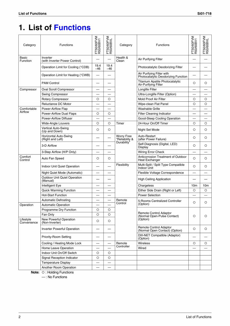
1. List of Functions
Category Functions
FT
50/6
0FV
MR
50/6
0BV
1
FT
50/6
0FV
MR
50/6
0BV
L
Category Functions
FT
50/6
0FV
MR
50/6
0BV
1
FT
50/6
0FV
MR
50/6
0BV
L
Basic Function
Inverter (with Inverter Power Control) — — Health &
Clean Air Purifying Filter — —
Operation Limit for Cooling (°CDB) 19.4~46
19.4~46 Photocatalytic Deodorizing Filter — —
Operation Limit for Heating (°CWB) — — Air Purifying Filter with Photocatalytic Deodorizing Function — —
PAM Control — — Titanium Apatite PhotocatalyticAir-Purifying Filter
Compressor Oval Scroll Compressor — — Longlife Filter — —
Swing Compressor — — Ultra-Longlife Filter (Option) — —
Rotary Compressor Mold Proof Air Filter
Reluctance DC Motor — — Wipe-clean Flat Panel
Comfortable Airflow
Power-Airflow Flap — — Washable Grille — —
Power-Airflow Dual Flaps Filter Cleaning Indicator — —
Power-Airflow Diffuser — — Good-Sleep Cooling Operation — —
Wide-Angle Louvers Timer 24-Hour On/Off Timer
Vertical Auto-Swing(Up and Down) Night Set Mode
Horizontal Auto-Swing(Right and Left) — — Worry Free
“Reliability & Durability”
Auto-Restart(after Power Failure)
3-D Airflow — — Self-Diagnosis (Digital, LED) Display
3-Step Airflow (H/P Only) — — Wiring Error Check — —
Comfort Control Auto Fan Speed Anticorrosion Treatment of Outdoor
Heat Exchanger
Indoor Unit Quiet Operation — — Flexibility Multi-Split / Split Type Compatible Indoor Unit
Night Quiet Mode (Automatic) — — Flexible Voltage Correspondence — —
Outdoor Unit Quiet Operation (Manual) — — High Ceiling Application — —
Intelligent Eye — — Chargeless 10m 10m
Quick Warming Function — — Either Side Drain (Right or Left)
Hot-Start Function — — Power Selection — —
Automatic Defrosting — — Remote Control
5-Rooms Centralized Controller (Option)Operation Automatic Operation — —
Programme Dry FunctionRemote Control Adaptor(Normal Open-Pulse Contact)(Option)
Fan Only
Lifestyle Convenience
New Powerful Operation(Non-Inverter)
Inverter Powerful Operation — — Remote Control Adaptor (Normal Open Contact) (Option)
Priority-Room Setting — — DIII-NET Compatible (Adaptor) (Option) — —
Cooling / Heating Mode Lock — — Remote Controller
Wireless
Home Leave Operation — — Wired — —
Indoor Unit On/Off Switch
Signal Reception Indicator
Temperature Display — —
Another Room Operation — —
Note: : Holding Functions— : No Functions
2 List of Functions

Si01-718 List of Functions
Category Functions
FT
50/6
0FV
MR
50/6
0CV
1A
Category Functions
FT
50/6
0FV
MR
50/6
0CV
1A
Basic Function
Inverter (with Inverter Power Control) — Health &
Clean Air Purifying Filter —
Operation Limit for Cooling (°CDB) 19.4~46 Photocatalytic Deodorizing Filter —
Operation Limit for Heating (°CWB) — Air Purifying Filter with Photocatalytic Deodorizing Function —
PAM Control — Titanium Apatite PhotocatalyticAir-Purifying Filter
Compressor Oval Scroll Compressor — Longlife Filter —
Swing Compressor — Ultra-Longlife Filter (Option) —
Rotary Compressor Mold Proof Air Filter
Reluctance DC Motor — Wipe-clean Flat Panel
Comfortable Airflow
Power-Airflow Flap — Washable Grille —
Power-Airflow Dual Flaps Filter Cleaning Indicator —
Power-Airflow Diffuser — Good-Sleep Cooling Operation —
Wide-Angle Louvers Timer 24-Hour On/Off Timer
Vertical Auto-Swing(Up and Down) Night Set Mode
Horizontal Auto-Swing(Right and Left) — Worry Free
“Reliability & Durability”
Auto-Restart(after Power Failure)
3-D Airflow — Self-Diagnosis (Digital, LED) Display
3-Step Airflow (H/P Only) — Wiring Error Check —
Comfort Control Auto Fan Speed Anticorrosion Treatment of Outdoor
Heat Exchanger
Indoor Unit Quiet Operation — Flexibility Multi-Split / Split Type Compatible Indoor Unit
Night Quiet Mode (Automatic) — Flexible Voltage Correspondence —
Outdoor Unit Quiet Operation (Manual) — High Ceiling Application —
Intelligent Eye — Chargeless 30m
Quick Warming Function — Either Side Drain (Right or Left)
Hot-Start Function — Power Selection —
Automatic Defrosting — Remote Control
5-Rooms Centralized Controller (Option)Operation Automatic Operation —
Programme Dry FunctionRemote Control Adaptor(Normal Open-Pulse Contact)(Option)
Fan Only
Lifestyle Convenience
New Powerful Operation(Non-Inverter)
Inverter Powerful Operation — Remote Control Adaptor (Normal Open Contact) (Option)
Priority-Room Setting — DIII-NET Compatible (Adaptor) (Option) —
Cooling / Heating Mode Lock — Remote Controller
Wireless
Home Leave Operation — Wired —
Indoor Unit On/Off Switch
Signal Reception Indicator
Temperature Display —
Another Room Operation —
Note: : Holding Functions— : No Functions
List of Functions 3

List of Functions Si01-718
4 List of Functions

Si01-718
Specifications 5
Part 2 Specifications
1. Specifications ..........................................................................................6

Specifications Si01-718
1. Specifications50Hz 220-230-240V
Note: The data are based on the conditions shown in the table below.
ModelsIndoor Units FT50FVM FT60FVMOutdoor Units R50BV1 R60BV1
Capacity (Rated)kW 5.3 6.6
Btu/h 18,090 22,530kcal/h 4,560 5,630
Running Current (Rated) A 7.9-7.6-7.2 11.6-11.1-10.6Power Consumption (Rated) W 1,650 2,460Power Factor % 94.9-94.4-95.5 96.4-96.4-96.7COP (Rated) W/W 3.21 2.68
Piping Connections
Liquid mm φ 6.4 φ 6.4Gas mm φ15.9 φ15.9Drain mm φ18.0 φ18.0
Heat Insulation Both Liquid and Gas Pipes Both Liquid and Gas PipesMax. Interunit Piping Length m 30 30Max. Interunit Height Difference m 15 15Chargeless m 10 10Amount of Additional Chargeof Refrigerant g/m 20 20
Indoor Units FT50FVM FT60FVMFront Panel Color White White
Air Flow Rate m³/min(cfm)
H 16.2 (572) 17.5 (618)M 14.0 (494) 15.0 (530)L 11.9 (420) 12.5 (441)
FanType Cross Flow Fan Cross Flow FanMotor Output W 43 43Speed Steps 5 Steps, Auto 5 Steps, Auto
Air Direction Control Right, Left, Horizontal, Downward Right, Left, Horizontal, DownwardAir Filter Removable/Washable/Mildew Proof Removable/Washable/Mildew ProofRunning Current A 0.19-0.18-0.17 0.21-0.20-0.19Power Consumption W 40 45Power Factor % 95.7-96.6-98.0 97.4-97.8-98.7Temperature Control Microcomputer Control Microcomputer ControlDimensions (H×W×D) mm 290×1,050×238 290×1,050×238Packaged Dimensions (H×W×D) mm 337×1,147×366 337×1,147×366Weight kg 12 12Gross Weight kg 17 17Operation Sound H/M/L dBA 45/41/35 47/42/36
Outdoor Units R50BV1 R60BV1Casing Color Ivory White Ivory White
CompressorType Hermetically Sealed Rotary Type Hermetically Sealed Rotary TypeModel RC60V1TNRT NH41VMDTMotor Output W 1,500 2,200
Refrigerant Oil
Type SUNISO 4GSD. I. MS-32Charge L 0.85 1.20
RefrigerantType R-22 R-22Charge kg 1.35 1.70
Air Flow Rate m³/min (cfm)H 40.0-40.5-41.0 (1,412-1,430-1,448) 40.0-40.5-41.0 (1,412-1,430-1,448)L — (—) 23.3-24.8-26.2 (823-876-925)
FanType Propeller PropellerMotor Output W 53 53
Running Current (Rated) A 7.71-7.42-7.03 11.39-10.90-10.41Power Consumption (Rated) W 1,610 2,415Power Factor % 94.9-94.3-95.4 96.4-96.3-96.7Starting Current A 32-33.5-35 55-57.5-60Dimensions (H×W×D) mm 685×800×300 685×800×300Packaged Dimensions (H×W×D) mm 732×955×390 732×955×390Weight kg 49 61Gross Weight kg 54 66Operation Sound dBA 54-54-55 54-54-55Drawing No. 3D056213 3D056215
Conversion Formulae
kcal/h=kW×860Btu/h=kW×3414
cfm=m³/min×35.3
Cooling Piping Length
Indoor ; 27°CDB/19°CWB Outdoor ; 35°CDB/24°CWB 7.5m
6 Specifications
Si01-718 Specifications
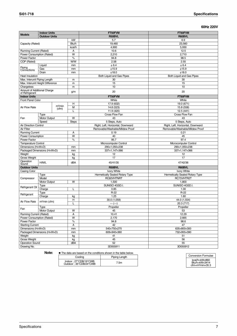
60Hz 220V
Note: The data are based on the conditions shown in the table below.
ModelsIndoor Units FT50FVM FT60FVMOutdoor Units R50BVL R60BVL
Capacity (Rated)kW 5.7 6.9
Btu/h 19,460 23,560kcal/h 4,900 5,930
Running Current (Rated) A 10.6 12.5Power Consumption (Rated) W 2,210 2,710Power Factor % 94.8 98.5COP (Rated) W/W 2.58 2.55
Piping Connections
Liquid mm φ 6.4 φ 6.4Gas mm φ15.9 φ15.9Drain mm φ18.0 φ18.0
Heat Insulation Both Liquid and Gas Pipes Both Liquid and Gas PipesMax. Interunit Piping Length m 30 30Max. Interunit Height Difference m 15 15Chargeless m 10 10Amount of Additional Chargeof Refrigerant g/m 20 20
Indoor Units FT50FVM FT60FVMFront Panel Color White White
Air Flow Rate m³/min(cfm)
H 17.9 (632) 19.0 (671)M 14.8 (523) 15.8 (558)L 11.9 (420) 12.5 (441)
FanType Cross Flow Fan Cross Flow FanMotor Output W 43 43Speed Steps 5 Steps, Auto 5 Steps, Auto
Air Direction Control Right, Left, Horizontal, Downward Right, Left, Horizontal, DownwardAir Filter Removable/Washable/Mildew Proof Removable/Washable/Mildew ProofRunning Current A 0.19 0.21Power Consumption W 40 45Power Factor % 95.7 97.4Temperature Control Microcomputer Control Microcomputer ControlDimensions (H×W×D) mm 290×1,050×238 290×1,050×238Packaged Dimensions (H×W×D) mm 337×1,147×366 337×1,147×366Weight kg 12 12Gross Weight kg 17 17Operation Sound H/M/L dBA 45/41/35 47/42/36
Outdoor Units R50BVL R60BVLCasing Color Ivory White Ivory White
CompressorType Hermetically Sealed Rotary Type Hermetically Sealed Rotary TypeModel RC60VHTNRT RC75VHTR2TMotor Output W 1,500 1,800
Refrigerant OilType SUNISO 4GSD.I. SUNISO 4GSD.I.Charge L 0.85 1.00
RefrigerantType R-22 R-22Charge kg 1.25 1.60
Air Flow Rate m³/min (cfm)H 30.0 (1,059) 44.0 (1,554)L — (—) 20.3 (717)
FanType Propeller PropellerMotor Output W 45 53
Running Current (Rated) A 10.41 12.29Power Consumption (Rated) W 2,170 2,665Power Factor % 94.8 98.6Starting Current A 42 47Dimensions (H×W×D) mm 540×750×270 635×800×300Packaged Dimensions (H×W×D) mm 609×940×360 732×955×390Weight kg 41 51Gross Weight kg 45 56Operation Sound dBA 52 55Drawing No. 3D055911 3D055912
Conversion Formulae
kcal/h=kW×860Btu/h=kW×3414
cfm=m³/min×35.3
Cooling Piping Length
Indoor ; 27°CDB/19°CWB Outdoor ; 35°CDB/24°CWB 7.5m
Specifications 7
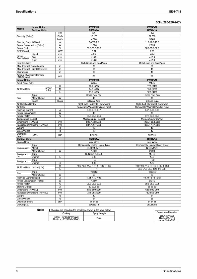
Specifications Si01-718
50Hz 220-230-240V
Note: The data are based on the conditions shown in the table below.
ModelsIndoor Units FT50FVM FT60FVMOutdoor Units R50CV1A R60CV1A
Capacity (Rated)kW 5.3 6.6
Btu/h 18,100 22,500kcal/h 4,560 5,680
Running Current (Rated) A 7.4-7.3-7.2 11.0-10.9-10.8Power Consumption (Rated) W 1,600 2,390Power Factor % 98.3-95.3-92.6 98.8-95.3-92.2COP (Rated) W/W 3.31 2.76
Piping Connections
Liquid mm φ 6.4 φ 6.4Gas mm φ15.9 φ15.9Drain mm φ18.0 φ18.0
Heat Insulation Both Liquid and Gas Pipes Both Liquid and Gas PipesMax. Interunit Piping Length m 30 30Max. Interunit Height Difference m 15 15Chargeless m 10 10Amount of Additional Chargeof Refrigerant g/m 20 20
Indoor Units FT50FVM FT60FVMFront Panel Color White White
Air Flow Rate m³/min(cfm)
H 16.2 (572) 17.5 (618)M 14.0 (494) 15.0 (530)L 11.9 (420) 12.5 (441)
FanType Cross Flow Fan Cross Flow FanMotor Output W 43 43Speed Steps 5 Steps, Auto 5 Steps, Auto
Air Direction Control Right, Left, Horizontal, Downward Right, Left, Horizontal, DownwardAir Filter Removable/Washable/Mildew Proof Removable/Washable/Mildew ProofRunning Current A 0.19-0.18-0.17 0.21-0.20-0.19Power Consumption W 40 45Power Factor % 95.7-96.6-98.0 97.4-97.8-98.7Temperature Control Microcomputer Control Microcomputer ControlDimensions (H×W×D) mm 290×1,050×238 290×1,050×238Packaged Dimensions (H×W×D) mm 337×1,147×366 337×1,147×366Weight kg 12 12Gross Weight kg 17 17Operation Sound H/M/L dBA 43/39/35 46/41/36
Outdoor Units R50CV1A R60CV1ACasing Color Ivory White Ivory White
CompressorType Hermetically Sealed Rotary Type Hermetically Sealed Rotary TypeModel RC60V1TNRT NH41VMDTMotor Output W 1,500 2,200
Refrigerant Oil
Type SUNISO 4GSD. I. MS-32Charge L 0.85 1.20
RefrigerantType R-22 R-22Charge kg 1.35 1.70
Air Flow Rate m³/min (cfm)H 40.0-40.5-41.0 (1,412-1,430-1,448) 40.0-40.5-41.0 (1,412-1,430-1,448)L — (—) 23.3-24.8-26.2 (823-876-925)
FanType Propeller PropellerMotor Output W 53 53
Running Current (Rated) A 7.21-7.12-7.03 10.79-10.70-10.61Power Consumption (Rated) W 1,560 2,345Power Factor % 98.3-95.3-92.5 98.8-95.3-92.1Starting Current A 32-33.5-35 55-58-60Dimensions (H×W×D) mm 685×800×300 685×800×300Packaged Dimensions (H×W×D) mm 732×955×390 732×955×390Weight kg 49 61Gross Weight kg 54 66Operation Sound dBA 54-54-55 54-54-55Drawing No. 3D056214 3D056216
Conversion Formulae
kcal/h=kW×860Btu/h=kW×3414
cfm=m³/min×35.3
Cooling Piping Length
Indoor ; 27°CDB/19°CWB Outdoor ; 35°CDB/24°CWB 7.5m
8 Specifications
Si01-718
Printed Circuit Board Connector Wiring Diagram 9
Part 3Printed Circuit Board
Connector Wiring Diagram
1. Printed Circuit Board Connector Wiring Diagram..................................101.1 Indoor Unit..............................................................................................10

Printed Circuit Board Connector Wiring Diagram Si01-718
1. Printed Circuit Board Connector Wiring Diagram1.1 Indoor Unit1.1.1 FT50/60FVM
Connectors PCB (1) (Control PCB)
PCB (2) (Signal Receiver PCB)
PCB (3) (Buzzer PCB)
PCB (4) (Display PCB)
Note: Other designationsPCB (1) (Control PCB)
PCB (2) (Signal Receiver PCB)
PCB (3) (Buzzer PCB)
PCB (4) (Display PCB)
1) S1 Connector for DC fan motor2) S6 Connector for swing motor (horizontal blades)3) S8 Connector for swing motor (vertical blades) (FT50/60DSG model)4) S21 Connector for centralized control (HA)5) S26 Connector for buzzer PCB6) S28 Connector for signal receiver PCB7) S32 Connector for heat exchanger thermistor8) H1, H2, H3 Connector for terminal strip
1) S29 Connector for control PCB
1) S27 Connector for control PCB2) S38 Connector for display PCB
1) S37 Connector for buzzer PCB
1) V1, V2 Varistor2) JA Address setting jumper
JB Fan speed setting when compressor is OFF on thermostatJC Power failure recovery function
∗ Refer to page 87 for detail.3) FU1 Fuse (3.15A)4) LED A LED for service monitor (green)
1) SW1 ON/OFF switch
1) RTH1 Room temperature thermistor
1) LED1 LED for operation (green)2) LED2 LED for timer (yellow)
10 Printed Circuit Board Connector Wiring Diagram

Si01-718 Printed Circuit Board Connector Wiring Diagram
PCB Detail PCB(1): Control PCB
PCB(2): Signal Receiver PCB PCB(3): Buzzer PCB
PCB(4): Display PCB
S1
V2
V1
H3
H2
FU1
H1
S6
S8
S26(R4003)
S28S32LED A JCJBJA
S21
SW1
S29
(R2861)
(R2862)RTH1
S38
S27
LED1 LED2 S37(R3087)
Printed Circuit Board Connector Wiring Diagram 11

Printed Circuit Board Connector Wiring Diagram Si01-718
12 Printed Circuit Board Connector Wiring Diagram
Si01-718
Details of Functions 13
Part 4Details of Functions
1. Main Functions......................................................................................141.1 Power-Airflow Dual Flaps, Wide Angle Louvers and Auto-Swing ..........141.2 Fan Speed Control for Indoor Units........................................................151.3 Thermostat Control.................................................................................161.4 Programme Dry Function .......................................................................171.5 Night Set Mode.......................................................................................181.6 POWERFUL Operation ..........................................................................191.7 Other Functions......................................................................................20
Main Functions Si01-718
1. Main Functions1.1 Power-Airflow Dual Flaps, Wide Angle Louvers and
Auto-Swing
Power-airflow Dual Flaps
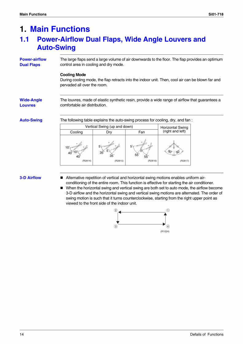
The large flaps send a large volume of air downwards to the floor. The flap provides an optimum control area in cooling and dry mode.
Cooling ModeDuring cooling mode, the flap retracts into the indoor unit. Then, cool air can be blown far and pervaded all over the room.
Wide-Angle Louvres
The louvres, made of elastic synthetic resin, provide a wide range of airflow that guarantees a comfortable air distribution.
Auto-Swing The following table explains the auto-swing process for cooling, dry, and fan :
3-D Airflow Alternative repetition of vertical and horizontal swing motions enables uniform air-conditioning of the entire room. This function is effective for starting the air conditioner.When the horizontal swing and vertical swing are both set to auto mode, the airflow become 3-D airflow and the horizontal swing and vertical swing motions are alternated. The order of swing motion is such that it turns counterclockwise, starting from the right upper point as viewed to the front side of the indoor unit.
Vertical Swing (up and down) Horizontal Swing (right and left)Cooling Dry Fan
10˚
40˚10˚40˚
(R2814)
5˚
35˚5˚
35˚
(R2815)
5˚
55˚5
55˚(R2816)
50˚ 50˚
(R2817)
(R1024)
14 Defails of Functions

Si01-718 Main Functions
1.2 Fan Speed Control for Indoor Units
Control Mode The airflow rate can be automatically controlled depending on the difference between the set temperature and the room temperature. This is done through rotation speed control and Hall IC control.
For more information about Hall IC, refer to the troubleshooting for fan motor on page 52.
Fan Speed Steps Fan speed control contains 9 steps: LLL, LL, SL, L, ML, M, MH, H and HH.In automatic operation, the step “SL” is not available.
= Within this range the airflow rate is automatically controlled when the FAN setting button is set to automatic.
Note: 1. During powerful operation, fan operates H tap + 90 rpm.2. In time of thermostat OFF, the fan rotates at the set tap.
Automatic Air Flow Control for Cooling
The following drawing explains the principle of fan speed control for cooling:
Step Cooling Dry mode
LL
800 - 950 rpm
L
ML
M
MH
H
HH (Powerful)(R2818)
+1.5˚C
+0.5˚C
+2˚C
+1˚C
M
ML
L
fan speed
Difference between room
and set temperature
Phase control
Thermostat
setting
temperature (R2820)
Defails of Functions 15

Main Functions Si01-718
1.3 Thermostat ControlThermostat control is based on the difference between the room temperature and the setpoint.
Thermostat OFF ConditionThe temperature difference is in the zone A.
Thermostat ON ConditionThe temperature difference is above the zone C after being in the zone A.The system resumes from defrost control in any zones except A.The operation turns on in any zones except A.The monitoring time has passed while the temperature difference is in the zone B.(Cooling / Dry : 10 minutes.)
Cooling / Dry
B
A
OFF
ON
C
Cooling : –0.5˚CDry : –0.5˚C
Room temperature - setpoint
Cooling : –2.0˚CDry : –2.5~–2.0˚C
(R4668)
16 Defails of Functions

Si01-718 Main Functions
1.4 Programme Dry FunctionProgramme dry function removes humidity while preventing the room temperature from lowering.Since the microcomputer controls both the temperature and air flow volume, the temperature adjustment and fan adjustment buttons are inoperable in this mode.
In Case of Inverter Units
The microcomputer automatically sets the temperature and fan settings. The difference between the room temperature at startup and the temperature set by the microcomputer is divided into two zones. Then, the unit operates in the dry mode with an appropriate capacity for each zone to maintain the temperature and humidity at a comfortable level.
Room temperature at startup
Set temperature X
Thermostat OFF pointY
Thermostat ON pointZ
24ºC or more
Room temperature at startup
X – 2.5ºC
X – 0.5ºCor
Y + 0.5ºC (zone B) continues for 10 min.
23.5ºC
X – 2.0ºC
X – 0.5ºCor
Y + 0.5ºC (zone B) continues for 10 min.
~
18ºC
18ºC X – 2.0ºC
X – 0.5ºC = 17.5ºCor
Y + 0.5ºC (zone B) continues for 10 min.
17.5ºC
~
Z
Y
Zone BZone B
Zone A = Thermostat OFF
Zone C = Thermostat ON
+0.5ºC
(R6841)
Defails of Functions 17

Main Functions Si01-718
1.5 Night Set ModeWhen the OFF timer is set, the Night Set circuit automatically activates.The Night Set circuit maintains the airflow setting made by users.
The Night Set Circuit
The Night Set circuit continues cooling the room at the set temperature for the first one hour, then automatically raises the temperature setting slightly for economical operations. This prevents excessive cooling to ensure comfortable sleeping conditions, and also conserves electricity.
Cooling Operation
18 Defails of Functions

Si01-718 Main Functions
1.6 POWERFUL Operation
Outline In order to exploit the cooling capacity to full extent, operate the air conditioner by increasing the indoor fan rotating speed and the compressor frequency.
Details of the Control
When Powerful button is pushed in each operation mode, the fan speed/setting temperature will be converted to the following states in a period of twenty minutes.
Ex.) : Powerful operation in cooling mode.
Operation mode Fan speed Target set temperature
Cooling H tap + 90 rpm 18°C
Dry Dry rotating speed + 50 rpm
Normally targeted temperature in dry
operation; Approx. –2°C
Fan H tap + 90 rpm —
(R4834)
Target temp.
Fan
90rpm
Set temp.
18˚C
Powerful ON
Powerful OFF
H tap
Set tap
It should be the lower limit of cooling temperature.
It counts 20 min. also in the remote controller.
Ending condition: "or" in 1 to 31. After the lapse of 20 minutes.2. Stop3. Powerful operation is OFF.20min.
Defails of Functions 19
Main Functions Si01-718
1.7 Other Functions1.7.1 Signal Receiving Sign
When the indoor unit receives a signal from the remote controller, the unit emits a signal receiving sound.
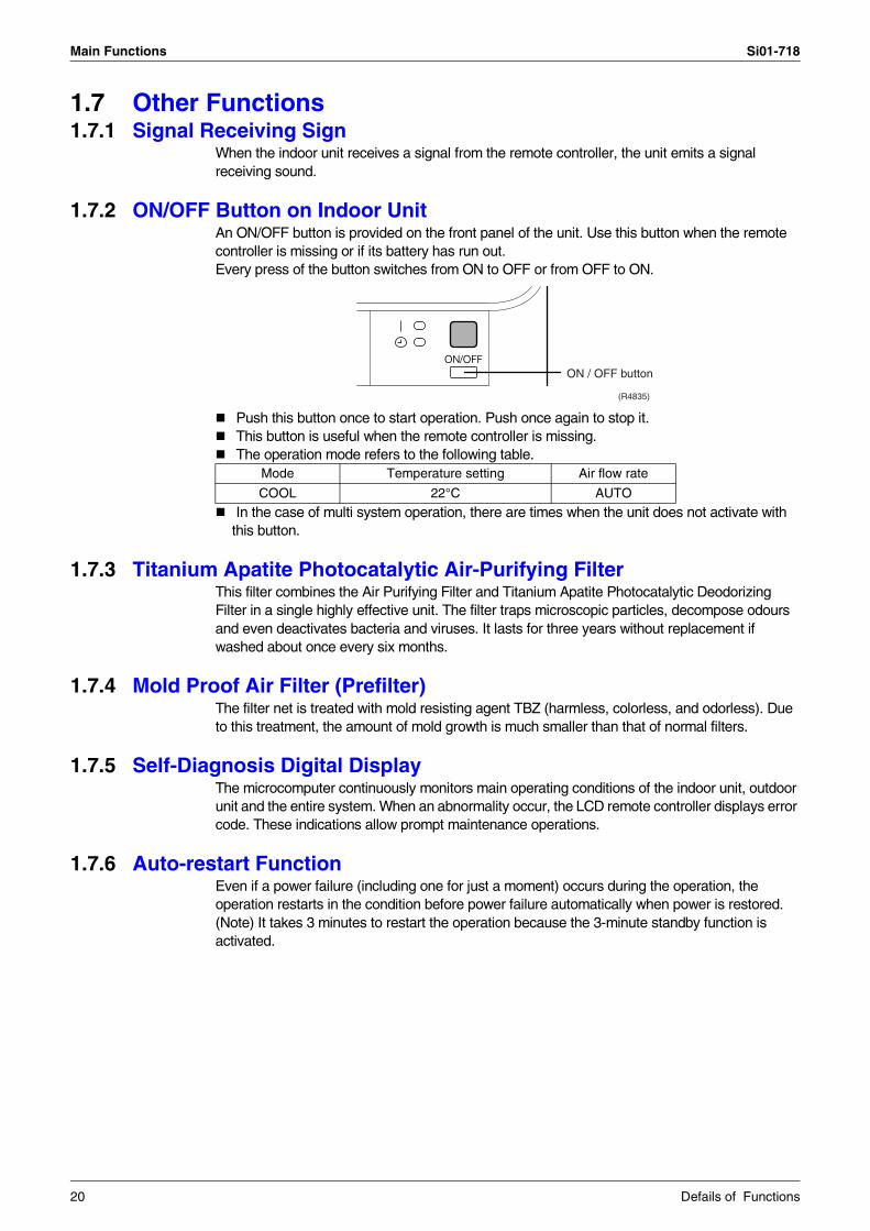
1.7.2 ON/OFF Button on Indoor UnitAn ON/OFF button is provided on the front panel of the unit. Use this button when the remote controller is missing or if its battery has run out. Every press of the button switches from ON to OFF or from OFF to ON.
Push this button once to start operation. Push once again to stop it.This button is useful when the remote controller is missing.The operation mode refers to the following table.
In the case of multi system operation, there are times when the unit does not activate with this button.
1.7.3 Titanium Apatite Photocatalytic Air-Purifying FilterThis filter combines the Air Purifying Filter and Titanium Apatite Photocatalytic Deodorizing Filter in a single highly effective unit. The filter traps microscopic particles, decompose odours and even deactivates bacteria and viruses. It lasts for three years without replacement if washed about once every six months.
1.7.4 Mold Proof Air Filter (Prefilter)The filter net is treated with mold resisting agent TBZ (harmless, colorless, and odorless). Due to this treatment, the amount of mold growth is much smaller than that of normal filters.
1.7.5 Self-Diagnosis Digital DisplayThe microcomputer continuously monitors main operating conditions of the indoor unit, outdoor unit and the entire system. When an abnormality occur, the LCD remote controller displays error code. These indications allow prompt maintenance operations.
1.7.6 Auto-restart FunctionEven if a power failure (including one for just a moment) occurs during the operation, the operation restarts in the condition before power failure automatically when power is restored.(Note) It takes 3 minutes to restart the operation because the 3-minute standby function is activated.
Mode Temperature setting Air flow rate
COOL 22°C AUTO
ON / OFF button
(R4835)
20 Defails of Functions

Si01-718
Operation Manual 21
Part 5Operation Manual
1. System Configuration............................................................................222. Instructions............................................................................................23
2.1 Safety Precautions .................................................................................232.2 Names of Parts.......................................................................................252.3 Preparation Before Operation ................................................................282.4 DRY · COOL · FAN Operation................................................................312.5 Adjusting the Air Flow Direction .............................................................332.6 POWERFUL Operation ..........................................................................342.7 TIMER Operation ...................................................................................352.8 Care and Cleaning .................................................................................372.9 Troubleshooting......................................................................................40

System Configuration Si01-718
1. System ConfigurationAfter the installation and test operation of the room air conditioner have been completed, it should be operated and handled as described below. Every user would like to know the correct method of operation of the room air conditioner, to check if it is capable of cooling well, and to know a clever method of using it.In order to meet this expectation of the users, giving sufficient explanations taking enough time can be said to reduce about 80% of the requests for servicing. However good the installation work is and however good the functions are, the customer may blame either the room air conditioner or its installation work because of improper handling. The installation work and handing over of the unit can only be considered to have been completed when its handling has been explained to the user without using technical terms but giving full knowledge of the equipment.
22 Operation Manual
Si01-718 Instructions
2. Instructions2.1 Safety Precautions
2
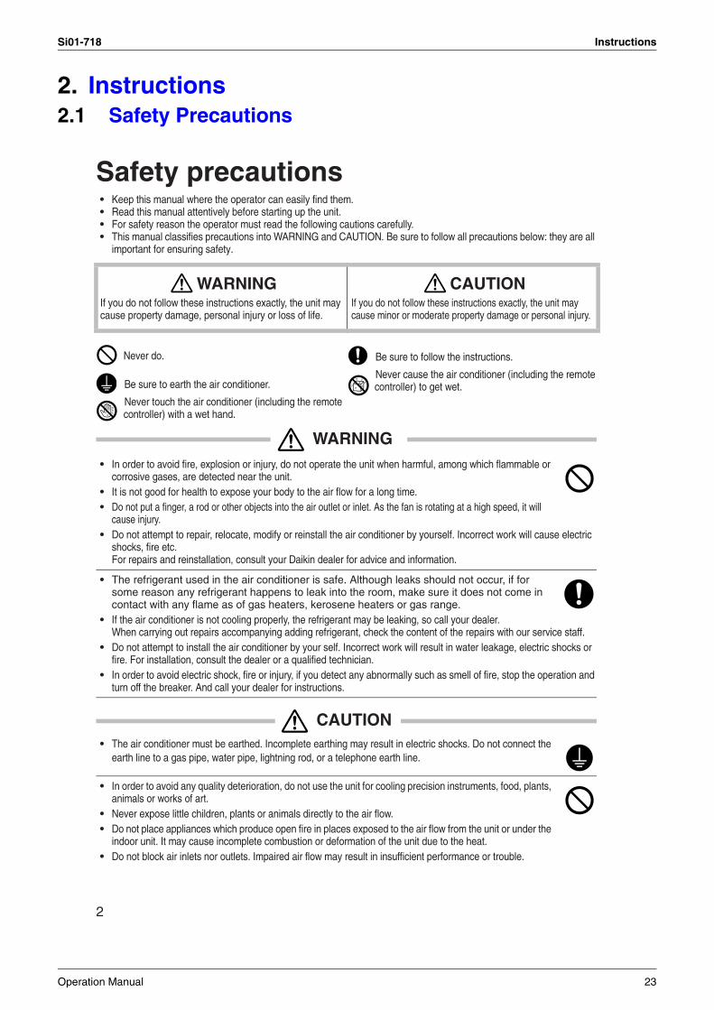
Safety precautions• Keep this manual where the operator can easily find them.• Read this manual attentively before starting up the unit.• For safety reason the operator must read the following cautions carefully.• This manual classifies precautions into WARNING and CAUTION. Be sure to follow all precautions below: they are all
important for ensuring safety.
WARNING• In order to avoid fire, explosion or injury, do not operate the unit when harmful, among which flammable or
corrosive gases, are detected near the unit.• It is not good for health to expose your body to the air flow for a long time.• Do not put a finger, a rod or other objects into the air outlet or inlet. As the fan is rotating at a high speed, it will
cause injury.• Do not attempt to repair, relocate, modify or reinstall the air conditioner by yourself. Incorrect work will cause electric
shocks, fire etc. For repairs and reinstallation, consult your Daikin dealer for advice and information.
• The refrigerant used in the air conditioner is safe. Although leaks should not occur, if for some reason any refrigerant happens to leak into the room, make sure it does not come in contact with any flame as of gas heaters, kerosene heaters or gas range.
• If the air conditioner is not cooling properly, the refrigerant may be leaking, so call your dealer.When carrying out repairs accompanying adding refrigerant, check the content of the repairs with our service staff.
• Do not attempt to install the air conditioner by your self. Incorrect work will result in water leakage, electric shocks or fire. For installation, consult the dealer or a qualified technician.
• In order to avoid electric shock, fire or injury, if you detect any abnormally such as smell of fire, stop the operation and turn off the breaker. And call your dealer for instructions.
CAUTION• The air conditioner must be earthed. Incomplete earthing may result in electric shocks. Do not connect the
earth line to a gas pipe, water pipe, lightning rod, or a telephone earth line.
• In order to avoid any quality deterioration, do not use the unit for cooling precision instruments, food, plants, animals or works of art.
• Never expose little children, plants or animals directly to the air flow.• Do not place appliances which produce open fire in places exposed to the air flow from the unit or under the
indoor unit. It may cause incomplete combustion or deformation of the unit due to the heat.• Do not block air inlets nor outlets. Impaired air flow may result in insufficient performance or trouble.
WARNINGIf you do not follow these instructions exactly, the unit may cause property damage, personal injury or loss of life.
CAUTIONIf you do not follow these instructions exactly, the unit may cause minor or moderate property damage or personal injury.
Never do. Be sure to follow the instructions.
Be sure to earth the air conditioner.Never cause the air conditioner (including the remote controller) to get wet.
Never touch the air conditioner (including the remote controller) with a wet hand.
Operation Manual 23

Instructions Si01-718
3
• Do not stand or sit on the outdoor unit. Do not place any object on the unit to avoid injury.• Do not place anything under the indoor or outdoor unit that must be kept away from moisture. In certain conditions,
moisture in the air may condense and drip.• After a long use, check the unit stand and fittings for damage.• Do not touch the air inlet and alminum fins of outdoor unit. It may cause injury.• The appliance is not intended for use by young children or infirm persons without supervision.• Young children should be supervised to ensure that they do not play with the appliance.
• To avoid oxygen deficiency, ventilate the room sufficiently if equipment with burner is used together with the air conditioner.
• Before cleaning, be sure to stop the operation, turn the breaker off or pull out the supply cord.• Do not connect the air conditioner to a power supply different from the one as specified. It may cause trou-
ble or fire.• Depending on the environment, an earth leakage breaker must be installed. Lack of an earth leakage breaker may
result in electric shocks.• Arrange the drain hose to ensure smooth drainage. Incomplete draining may cause wetting of the building, furniture
etc.• Do not place objects in direct proximity of the outdoor unit and do not let leaves and other debris accumulate around
the unit. Leaves are a hotbed for small animals which can enter the unit. Once in the unit, such animals can cause malfunc-tions, smoke or fire when making contact with electrical parts.
• Do not operate the air conditioner with wet hands.
• Do not wash the indoor unit with excessive water, only use a slightly wet cloth.• Do not place things such as vessels containing water or anything else on top of the unit. Water may pene-
trate into the unit and degrade electrical insulations, resulting in an electric shock.
To install the air conditioner in the following types of environments, consult the dealer.• Places with an oily ambient or where steam or soot occurs.• Salty environment such as coastal areas.• Places where sulfide gas occurs such as hot springs.• Places where snow may block the outdoor unit.
The drain from the outdoor unit must be discharged to a place of good drainage.
For installation, choose a place as described below.• A place solid enough to bear the weight of the unit which does not amplify the operation noise or vibration.• A place from where the air discharged from the outdoor unit or the operation noise will not annoy
your neighbours.
• For power supply, be sure to use a separate power circuit dedicated to the air conditioner.
• Relocating the air conditioner requires specialized knowledge and skills. Please consult the dealer if reloca-tion is necessary for moving or remodeling.
Installation site.
Consider nuisance to your neighbours from noises.
Electrical work.
System relocation.
24 Operation Manual

Si01-718 Instructions
2.2 Names of Parts
4
Names of parts
Indoor Unit
12
43
9 10 86
7
13
11
12
14
5
Operation Manual 25

Instructions Si01-718
5
Outdoor Unit
Indoor Unit1. Air filter
2. Titanium Apatite PhotocatalyticAir-Purifying Filter
3. Air inlet
4. Front panel
5. Panel tab
6. Room temperature sensor:• It senses the air temperature around the unit.
7. Display
8. Air outlet
9. Flap (horizontal blade): (page 12.)
10. Louvers (vertical blades):• The Louvers are inside of the air outlet.
(page 12.)
11. Operation lamp (green)
12. TIMER lamp (yellow): (page 14.)
13. Indoor Unit ON/OFF switch:• Push this switch once to start operation.
Push once again to stop it.• The operation mode refer to the following table.
• This switch is useful when the remote controller is missing.
14. Signal receiver:• It receives signals from the remote controller.• When the unit receives a signal, you will hear a
short beep.• Operation start .............beep-beep• Settings changed..........beep• Operation stop ..............beeeeep
Outdoor Unit
15. Air inlet: (Back and side)
16. Air outlet
17. Refrigerant piping and inter-unit cable
18. Drain hose
19. Earth terminal:• It is inside of this cover.
20. Stop valve:• Dew condensation may form on the stop
valve during operation. This does not indicate any type of malfunction in the outdoor unit.
Appearance of the outdoor unit may differ from some models.
17
1619
18
17
15
20
ModeTemperature
settingAir flow rate
COOL 22°C AUTO
26 Operation Manual

Si01-718 Instructions
6
Remote Controller
1. Signal transmitter:• It sends signals to the indoor unit.
2. Display:• It displays the current settings.
(In this illustration, each section is shown with all its displays ON for the purpose of explanation.)
3. POWERFUL button: POWERFUL operation (page 13.)
4. TEMPERATURE adjustment buttons:• It changes the temperature setting.
5. ON/OFF button:• Press this button once to start operation.
Press once again to stop it.
6. MODE selector button:• It selects the operation mode.(DRY/COOL/FAN) (page 10.)
7. FAN setting button:• It selects the air flow rate setting.
8. SWING button: (page 12.)• Flap (Horizontal blade)
9. ON TIMER button: (page 15.)
10. OFF TIMER button: (page 14.)
11. TIMER Setting button:• It changes the time setting.
12. TIMER CANCEL button:• It cancels the timer setting.
13. CLOCK button: (page 9.)
14. RESET button:• Restart the unit if it freezes.• Use a thin object to push.
1
4
5
78
< ARC433A73 >
2
9
11
10
3
6
12
14
13
Operation Manual 27
Instructions Si01-718
2.3 Preparation Before Operation
7
Preparation Before Operation
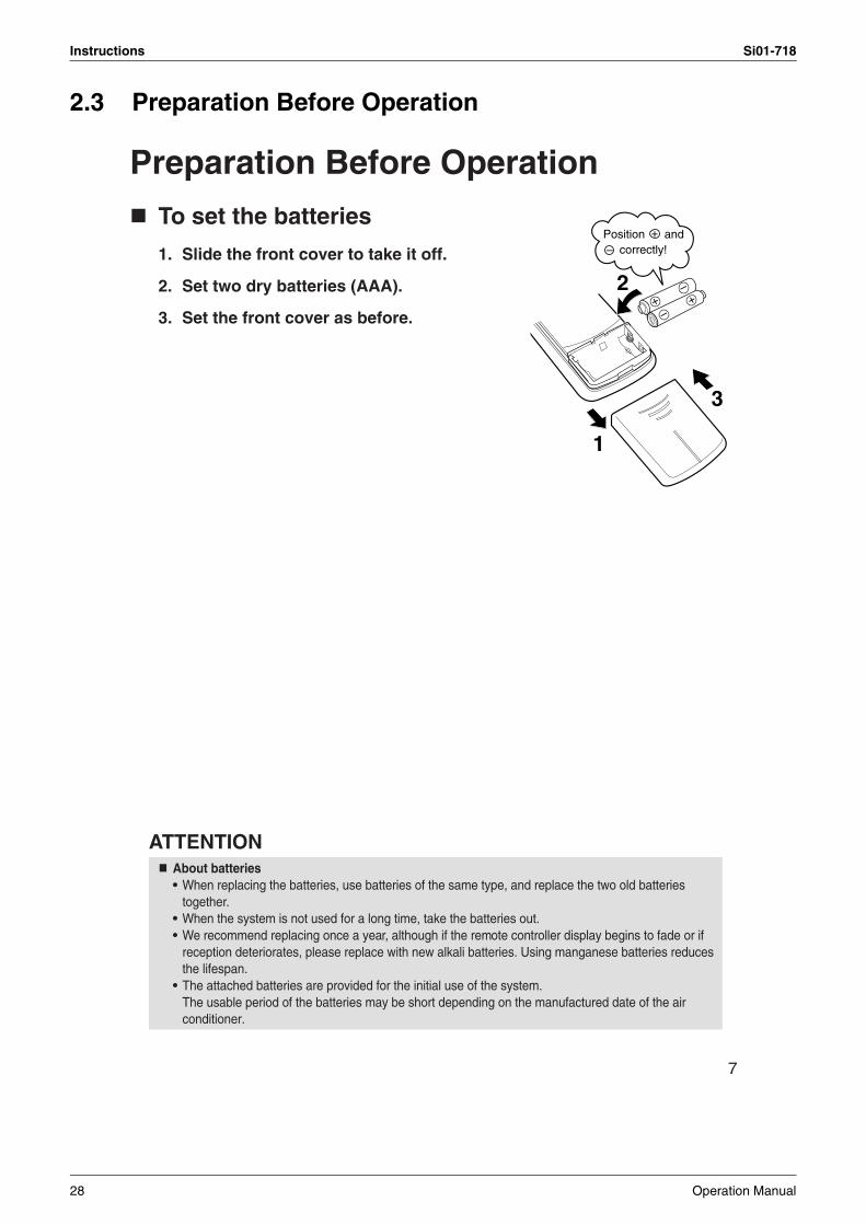
To set the batteries
1. Slide the front cover to take it off.
2. Set two dry batteries (AAA).
3. Set the front cover as before.
ATTENTIONAbout batteries• When replacing the batteries, use batteries of the same type, and replace the two old batteries
together.• When the system is not used for a long time, take the batteries out.• We recommend replacing once a year, although if the remote controller display begins to fade or if
reception deteriorates, please replace with new alkali batteries. Using manganese batteries reduces the lifespan.
• The attached batteries are provided for the initial use of the system.The usable period of the batteries may be short depending on the manufactured date of the air conditioner.
2
3
1
Position and correctly!
+–
28 Operation Manual

Si01-718 Instructions
8
Preparation Before Operation
To operate the remote controller• To use the remote controller, aim the transmitter
at the indoor unit. If there is anything to block signals between the unit and the remote controller, such as a curtain, the unit will not operate.
• Do not drop the remote controller. Do not get it wet.• The maximum distance for communication is
about 7m.
To fix the remote controller holder on the wall
1. Choose a place from where the signals reach the unit.
2. Fix the holder to a wall, a pillar, or similar location with the screws procured locally.
3. Place the remote controller in the remote controller holder.
ATTENTIONAbout remote controller• Never expose the remote controller to direct sunlight.• Dust on the signal transmitter or receiver will reduce the sensitivity. Wipe off dust with soft cloth.• Signal communication may be disabled if an electronic-starter-type fluorescent lamp (such as
inverter-type lamps) is in the room. Consult the shop if that is the case.• If the remote controller signals happen to operate another appliance, move that appliance to some-
where else, or consult the shop.
Receiver
Remote controller holder
Set.
To remove, pull it upwards.
Operation Manual 29

Instructions Si01-718
9
To set the clock
1. Press “CLOCK button”.
is displayed.
blinks.
2. Press “TIMER setting button” to set the clock to the present time.
Holding down “ ” or “ ” button rap-idly increases or decreases the time dis-play.
3. Press “CLOCK button”.
blinks.
Turn the breaker ON• Turning ON the breaker opens the flap,
then closes it again. (This is a normal procedure.)
NOTETips for saving energy• Be careful not to cool the room too much.
Keeping the temperature setting at a moderate level helps save energy.• Cover windows with a blind or a curtain.
Blocking sunlight and air from outdoors increases the cooling effect.• Clogged air filters cause inefficient operation and waste energy. Clean them
once in about every two weeks.Please note• The air conditioner always consumes 15-35 watts of electricity even while it is not operating.• If you are not going to use the air conditioner for a long period, for example in spring or autumn, turn the breaker
OFF.• Use the air conditioner in the following conditions.
• Operation outside this humidity or temperature range may cause a safety device to disable the system.
1, 3
2
Recommended temperature setting
For cooling: 26°C – 28°C
Mode Operating conditions If operation is continued out of this range
COOL Outdoor temperature: 20 to 46°CIndoor temperature: 18 to 32°CIndoor humidity: 80% max.
• A safety device may work to stop the operation.• Condensation may occur on the indoor unit and drip.
DRY Outdoor temperature: 20 to 46°CIndoor temperature: 18 to 32°CIndoor humidity: 80% max.
• A safety device may work to stop the operation.• Condensation may occur on the indoor unit and drip.
30 Operation Manual

Si01-718 Instructions
2.4 DRY · COOL · FAN Operation
10
DRY · COOL · FAN OperationThe air conditioner operates with the operation mode of your choice.From the next time on, the air conditioner will operate with the same operation mode.
To start operation1. Press “MODE selector button”
and select a operation mode.• Each pressing of the button advances the
mode setting in sequence.
: DRY
: COOL
: FAN
2. Press “ON/OFF button”.• The OPERATION lamp lights up.
To stop operation3. Press “ON/OFF button” again.
• Then OPERATION lamp goes off.
To change the temperature setting4. Press “TEMPERATURE adjustment button”.
DRY or FAN mode COOL mode
The temperature setting is not variable.
Press “ ” to raise the temperature and press
“ ” to lower the temperature.
Set to the temperature you like.
2, 31
4
5
Operation Manual 31

Instructions Si01-718
11
To change the air flow rate setting
5. Press “FAN setting button”.
NOTE
DRY mode COOL or FAN mode
The air flow rate setting is not variable.
Five levels of air flow rate setting from “ ” to “ ”
plus “ ” are available.
Note on COOL operation• This air conditioner cools the room by blowing the hot air in the room outside, so if the
outside temperature is high, performance drops.Note on DRY operation• The computer chip works to rid the room of humidity while maintaining the temperature as
much as possible. It automatically controls temperature and fan strength, so manual adjustment of these functions is unavailable.
Note on air flow rate setting• At smaller air flow rates, the cooling effect is also smaller.
32 Operation Manual

Si01-718 Instructions
2.5 Adjusting the Air Flow Direction
12
Adjusting the Air Flow DirectionYou can adjust the air flow direction to increase your com-fort.
To adjust the horizontal blade (flap)
1. Press “SWING button ”.• “ ” is displayed on the LCD.
2. When the flap has reached the desired position, press “SWING button ” once more.• The flap will stop moving.
• “ ” disappears from the LCD.
To adjust the vertical blades (louvers)
Hold the knob and move the louvers.(You will find a knob on the left-side and the right-side blades.)
Notes on flaps and louvers angles• When “SWING button” is selected, the flaps swinging range
depends on the operation mode. (See the figure.)
ATTENTION• Always use a remote controller to adjust the flaps angle. If
you attempt to move it forcibly with hand when it is swinging, the mechanism may be broken.
• Be careful when adjusting the louvers. Inside the air outlet, a fan is rotating at a high speed.
1, 2
STOP
COOLapprox. 10°~40°
DRYapprox. 5°~35°
In COOL or DRY mode
STOP
FANapprox. 5°~55°
In FAN mode
Operation Manual 33
Instructions Si01-718
2.6 POWERFUL Operation
13
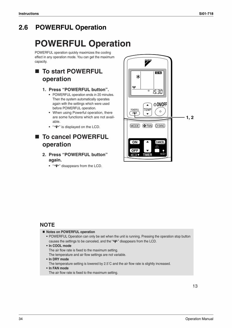
POWERFUL OperationPOWERFUL operation quickly maximizes the cooling effect in any operation mode. You can get the maximum capacity.
To start POWERFUL operation
1. Press “POWERFUL button”.• POWERFUL operation ends in 20 minutes.
Then the system automatically operates again with the settings which were used before POWERFUL operation.
• When using Powerful operation, there are some functions which are not avail-able.
• “ ” is displayed on the LCD.
To cancel POWERFUL operation
2. Press “POWERFUL button” again.• “ ” disappears from the LCD.
NOTENotes on POWERFUL operation• POWERFUL Operation can only be set when the unit is running. Pressing the operation stop button
causes the settings to be canceled, and the “ ” disappears from the LCD.• In COOL mode
The air flow rate is fixed to the maximum setting.The temperature and air flow settings are not variable.
• In DRY modeThe temperature setting is lowered by 2.5˚C and the air flow rate is slightly increased.
• In FAN modeThe air flow rate is fixed to the maximum setting.
1, 2
34 Operation Manual

Si01-718 Instructions
2.7 TIMER Operation
14
TIMER OperationTimer functions are useful for automatically switching the air conditioner on or off at night or in the morning. You can also use OFF TIMER and ON TIMER in combination.
To use OFF TIMER operation• Check that the clock is correct.
If not, set the clock to the present time. (page 9.)
1. Press “OFF TIMER button”.
is displayed.
blinks.
2. Press “TIMER Setting button” until the time setting reaches the point you like.• Every pressing of either button increases
or decreases the time setting by 10 min-utes. Holding down either button changes the setting rapidly.
3. Press “OFF TIMER button” again.• The TIMER lamp lights up.
To cancel the OFF TIMER Operation4. Press “CANCEL button”.
• The TIMER lamp goes off.
NOTE• When TIMER is set, the present time is not displayed.• Once you set ON, OFF TIMER, the time setting is kept in the memory. (The memory is canceled when
remote controller batteries are replaced.)• When operating the unit via the ON/OFF Timer, the actual length of operation may vary from the time
entered by the user. (Maximum approx. 10 minutes)
NIGHT SET MODEWhen the OFF TIMER is set, the air conditioner automatically adjusts the temperature setting (0.5°C up in COOL) to prevent excessive cooling for your pleasant sleep.
42
1, 3
Operation Manual 35

Instructions Si01-718
15
To use ON TIMER operation• Check that the clock is correct. If not, set the
clock to the present time.(page 9.)
1. Press “ON TIMER button”.
is displayed.
blinks.
2. Press “TIMER Setting button” until the time setting reaches the point you like.• Every pressing of either button increases
or decreases the time setting by 10 min-utes. Holding down either button changes the setting rapidly.
3. Press “ON TIMER button” again.• The TIMER lamp lights up.
To cancel ON TIMER operation4. Press “CANCEL button”.
• The TIMER lamp goes off.
To combine ON TIMER and OFF TIMER• A sample setting for combining the two timers is shown below.
ATTENTIONIn the following cases, set the timer again.• After a breaker has turned OFF.• After a power failure.• After replacing batteries in the remote controller.
2
1, 3
4
Dis
play
(Example)Present time: 11:00 p.m. (The unit operating)OFF TIMER at 0:00 a.m.ON TIMER at 7:00 a.m. Combined
36 Operation Manual

Si01-718 Instructions
2.8 Care and Cleaning
16
Care and CleaningCAUTION
Indoor unit, Outdoor unit and Remote controller1. Wipe them with dry soft cloth.
Front panel1. Open the front panel.
• Hold the panel by the tabs on the two sides and lift it until it stops with a click.
2. Remove the front panel.• Open the front panel further while
sliding it to either the left or right and pulling it toward you. This will disconnect the rotation dowel on one side. Then disconnect the rotation dowel on the other side in the same manner.
3. Clean the front panel.• Wipe it with a soft cloth soaked in water.• Only neutral detergent may be used.• In case of washing the panel with water, dry it with cloth, dry it up in the shade after washing.
4. Attach the front panel.• Align the rotation dowels on the left and right of the front panel with
the slots, then push them all the way in.• Close the front panel slowly. (Press the panel at both sides and the
center.)
CAUTION
Units
• Don’t touch the metal parts of the indoor unit. If you touch those parts, this may cause an injury.• When removing or attaching the front panel, use a robust and stable stool and watch your steps carefully.• When removing or attaching the front panel, support the panel securely with hand to prevent it from falling.• For cleaning, do not use hot water above 40°C, benzine, gasoline, thinner, nor other volatile oils,
polishing compound, scrubbing brushes, nor other hand stuff.• After cleaning, make sure that the front panel is securely fixed.
Before cleaning, be sure to stop the operation and turn the breaker OFF.
Operation Manual 37

Instructions Si01-718
17
1. Open the front panel. (page 16.)
2. Pull out the air filters.• Push a little upwards the tab at the
center of each air filter, then pull it down.
3. Take off the Titanium Apatite Photocatalytic Air-Purifying Filter.• Press the top of the air-
cleaning filter onto the tabs (3 tabs at top). Then press the bottom of the filter up slightly, and press it onto the tabs (3 at bottom).
4. Clean or replace each filter.See figure.
5. Set the air filter and the Titanium Apatite Photocatalytic Air-Purifying Filter as they were and close the front panel.• Press the front panel at both sides and the center.
Air Filter1. Wash the air filters with water or clean them with vacuum cleaner.
• If the dust does not come off easily, wash them with neutral detergent thinned with lukewarm water, then dry them up in the shade.
• It is recommended to clean the air filters every two weeks.
Titanium Apatite Photocatalytic Air-purifying Filter The Titanium Apatite Photocatalytic Air-Purifying Filter can be renewed by washing it with water once every 6 months. We recommend replacing it once every 3 years.
[ Maintenance ]1. Remove dust with a vacuum cleaner and wash lightly with water.2. If it is very dirty, soak it for 10 to 15 minutes in water mixed with a neutral cleaning agent.3. After washing, shake off remaining water and dry in the shade.4. Since the material is made out of polyester, do not wring out the filter
when removing water from it.
[ Replacement ]1. Remove the tabs on the filter frame and replace with a new filter.
• Dispose of the old filter as non-flammable waste.
Filters
tabs (3 tabs at top)
tabs (3 at bottom)
38 Operation Manual

Si01-718 Instructions
18
NOTE
Check
Before a long idle period
1. Operate the “FAN only” for several hours on a fine day to dry out the inside.• Press “MODE” button and select “FAN” operation.
• Press “ON/OFF” button and start operation.
2. After operation stops, turn off the breaker for the room air conditioner.
3. Clean the air filters and set them again.
4. Take out batteries from the remote controller.
• Operation with dirty filters: (1) cannot deodorize the air. (2) cannot clean the air. (3) results in poor cooling. (4) may cause odour.
• To order Titanium Apatite Photocatalytic Air-Purifying Filter contact to the service shop there you bought the air conditioner.
• Dispose of old filters as non-flammable waste.
Check that the base, stand and other fittings of the outdoor unit are not decayed or corroded.
Check that nothing blocks the air inlets and the outlets of the indoor unit and the outdoor unit.
Check that the drain comes smoothly out of the drain hose during COOL or DRY operation.• If no drain water is seen, water may be leaking from the indoor unit. Stop operation and consult the ser-
vice shop if this is the case.
Item Part No.
Titanium Apatite Photocatalytic Air-Purifying Filter (without frame) 1 set KAF952B42
Operation Manual 39
Instructions Si01-718
2.9 Troubleshooting
19
Trouble Shooting
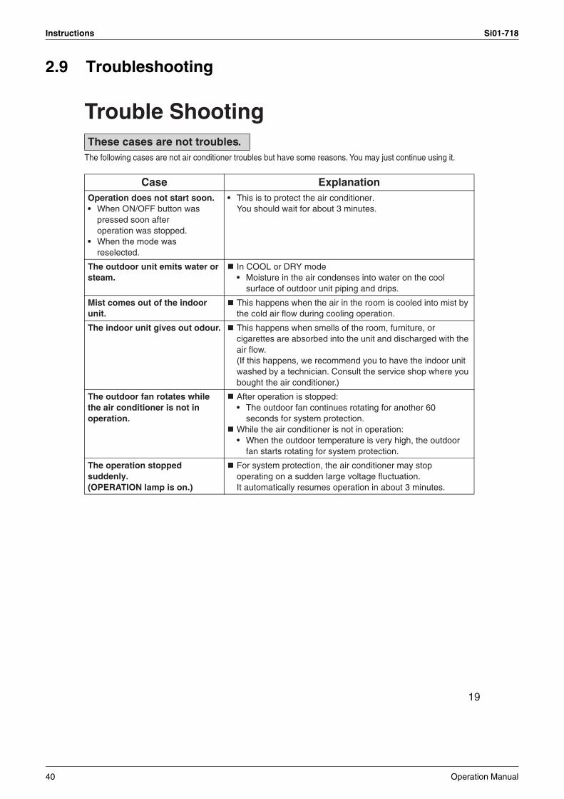
The following cases are not air conditioner troubles but have some reasons. You may just continue using it.
These cases are not troubles.
Case ExplanationOperation does not start soon.• When ON/OFF button was
pressed soon after operation was stopped.
• When the mode was reselected.
• This is to protect the air conditioner.You should wait for about 3 minutes.
The outdoor unit emits water or steam.
In COOL or DRY mode• Moisture in the air condenses into water on the cool
surface of outdoor unit piping and drips.
Mist comes out of the indoor unit.
This happens when the air in the room is cooled into mist by the cold air flow during cooling operation.
The indoor unit gives out odour. This happens when smells of the room, furniture, or cigarettes are absorbed into the unit and discharged with the air flow.(If this happens, we recommend you to have the indoor unit washed by a technician. Consult the service shop where you bought the air conditioner.)
The outdoor fan rotates while the air conditioner is not in operation.
After operation is stopped:• The outdoor fan continues rotating for another 60
seconds for system protection.While the air conditioner is not in operation:• When the outdoor temperature is very high, the outdoor
fan starts rotating for system protection.
The operation stopped suddenly.(OPERATION lamp is on.)
For system protection, the air conditioner may stop operating on a sudden large voltage fluctuation.It automatically resumes operation in about 3 minutes.
40 Operation Manual

Si01-718 Instructions
20
Please check again before calling a repair person.
Case CheckThe air conditioner does not operate.(OPERATION lamp is off.)
• Hasn’t a breaker turned OFF or a fuse blown?• Isn’t it a power failure?• Are batteries set in the remote controller?• Is the timer setting correct?
Cooling effect is poor. • Are the air filters clean?• Is there anything to block the air inlet or the outlet of the
indoor and the outdoor units?• Is the temperature setting appropriate?• Are the windows and doors closed?• Are the air flow rate and the air direction set appropriately?
Operation stops suddenly.(OPERATION lamp flashes.)
• Are the air filters clean?• Is there anything to block the air inlet or the outlet of the
indoor and the outdoor units?Clean the air filters or take all obstacles away and turn the breaker OFF. Then turn it ON again and try operating the air conditioner with the remote controller. If the lamp still blinks, call the service shop where you bought the air conditioner.
An abnormal functioninghappens during operation.
• The air conditioner may malfunction with lightning or radio waves. Turn the breaker OFF, turn it ON again and try operating the air conditioner with the remote controller.
Check again.
Operation Manual 41
Instructions Si01-718
3P192025-3
21
WARNING When an abnormality (such as a burning smell) occurs, stop operation and turn the breaker OFF.
Continued operation in an abnormal condition may result in troubles, electric shocks or fire.Consult the service shop where you bought the air conditioner.
Do not attempt to repair or modify the air conditioner by yourself.Incorrect work may result in electric shocks or fire.Consult the service shop where you bought the air conditioner.
If one of the following symptoms takes place, call the service shop immediately.
In certain operating conditions, the inside of the air conditioner may get foul after several seasons of use, resulting in poor performance. It is recommended to have periodical maintenance by a specialist aside from regular cleaning by the user. For specialist maintenance, contact the service shop where you bought the air conditioner.The maintenance cost must be born by the user.
Call the service shop
After a power failureThe air conditioner automatically resumes operation in about 3 minutes. You should just wait for a while.
LightningIf lightning may strike the neighbouring area, stop operation and turn the breaker OFF for system protection.
We . recommend periodical maintenance
immediately.
42 Operation Manual

Si01-718
Service Diagnosis 43
Part 6Service Diagnosis
1. Caution for Diagnosis............................................................................442. Troubleshooting by Symptoms..............................................................453. Service Check Function ........................................................................464. Troubleshooting ....................................................................................49
4.1 Error Codes and Description ..................................................................494.2 Indoor Unit PCB Abnormality .................................................................504.3 Freeze-up Protection Control .................................................................514.4 Fan Motor or Related Abnormality .........................................................524.5 Thermistor or Related Abnormality (Indoor Unit)....................................544.6 Indoor Unit PCB Abnormality .................................................................55
5. Check ....................................................................................................565.1 How to Check .........................................................................................56
Caution for Diagnosis Si01-718
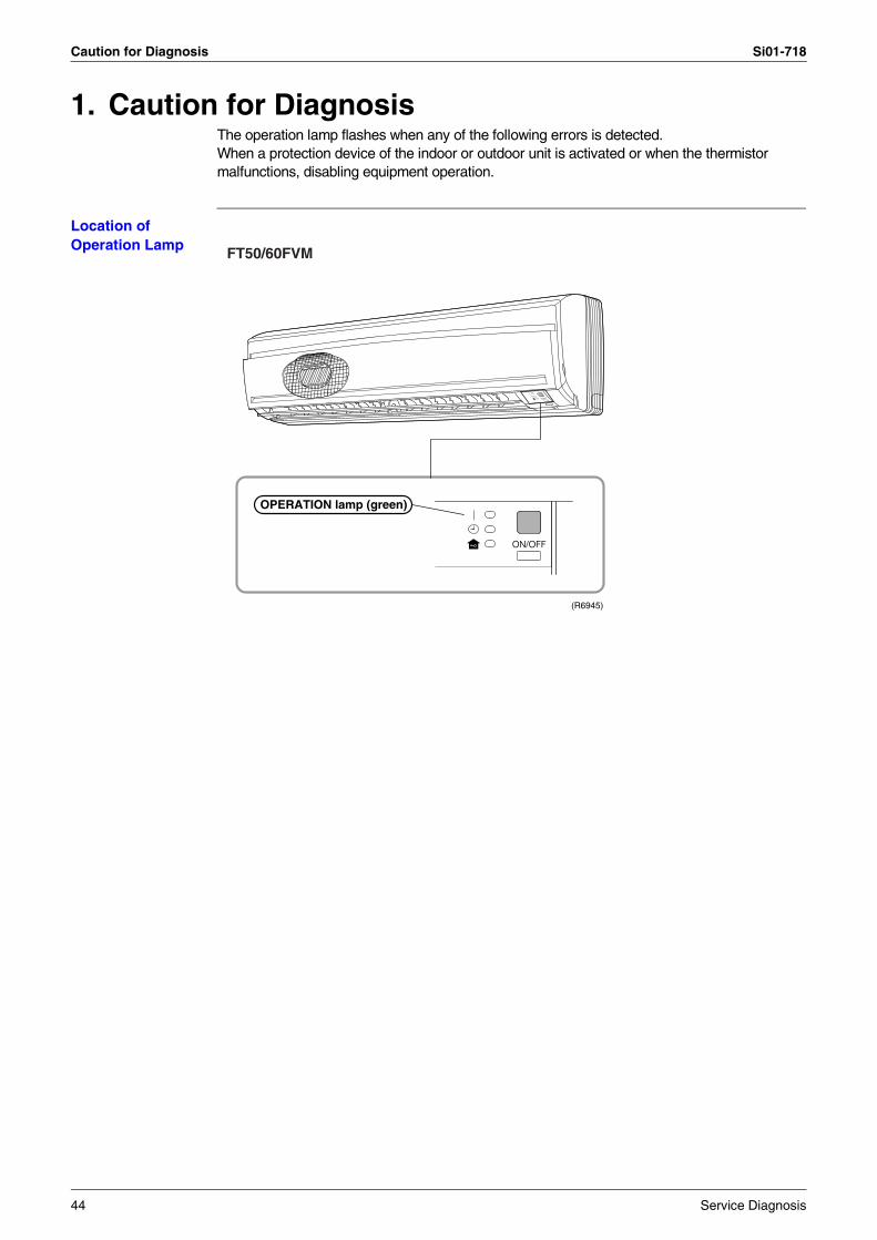
1. Caution for DiagnosisThe operation lamp flashes when any of the following errors is detected.When a protection device of the indoor or outdoor unit is activated or when the thermistor malfunctions, disabling equipment operation.
Location of Operation Lamp FT50/60FVM
(R6945)
OPERATION lamp (green)
44 Service Diagnosis

Si01-718 Troubleshooting by Symptoms
2. Troubleshooting by SymptomsSymptom Check Item Details of Measure Reference
Page
None of the units operates.
Check the power supply. Check to make sure that the rated voltage is supplied.
—
Check the type of the indoor units. Check to make sure that the indoor unit type is compatible with the outdoor unit.
—
Check the outside air temperature. Operation cannot be used when the outside temperature is below 19.4 °C.
—
Diagnose with remote controller indication.
— 49
Check the remote controller addresses.
Check to make sure that address settings for the remote controller and indoor unit are correct.
—
Operation sometimes stops.
Check the power supply. A power failure of 2 to 10 cycles can stop air conditioner operation. (Operation lamp OFF)
—
Check the outside air temperature. Operation cannot be used when the outside temperature is below 19.4°C.
—
Diagnose with remote controller indication.
— 49
Equipment operates but does not cool.
Check for thermistor detection errors.
Check to make sure that the main unit’s thermistor has not dismounted from the pipe holder.
—
Diagnose with remote controller indication.
— 49
Diagnose by service port pressure and operating current.
Check for insufficient gas. —
Large operating noise and vibrations
Check the installation condition. Check to make sure that the required spaces for installation (specified in the Engineering data book, etc.) are provided.
—
Service Diagnosis 45
Service Check Function Si01-718
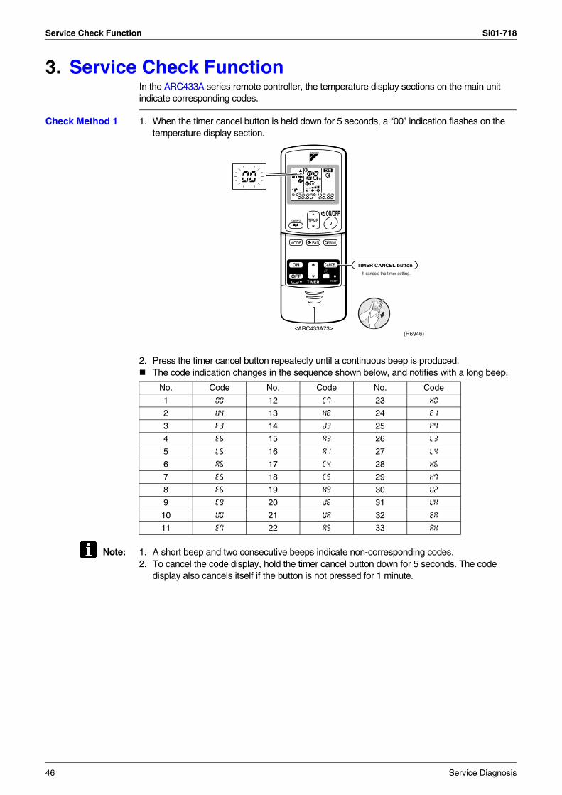
3. Service Check FunctionIn the ARC433A series remote controller, the temperature display sections on the main unit indicate corresponding codes.
Check Method 1 1. When the timer cancel button is held down for 5 seconds, a “00” indication flashes on the temperature display section.
2. Press the timer cancel button repeatedly until a continuous beep is produced.The code indication changes in the sequence shown below, and notifies with a long beep.
Note: 1. A short beep and two consecutive beeps indicate non-corresponding codes.2. To cancel the code display, hold the timer cancel button down for 5 seconds. The code
display also cancels itself if the button is not pressed for 1 minute.
No. Code No. Code No. Code
1 00 12 C7 23 H0
2 U4 13 H8 24 E1
3 F3 14 J3 25 P4
4 E6 15 A3 26 L3
5 L5 16 A1 27 L4
6 A6 17 C4 28 H6
7 E5 18 C5 29 H7
8 F6 19 H9 30 U2
9 C9 20 J6 31 UH
10 U0 21 UA 32 EA
11 E7 22 A5 33 AH
It cancels the timer setting.
(R6946)<ARC433A73>
TIMER CANCEL button
46 Service Diagnosis
Si01-718 Service Check Function
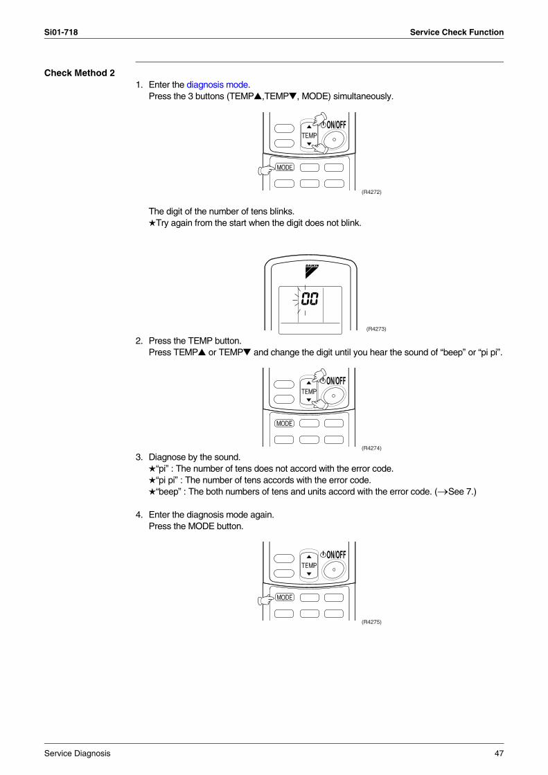
Check Method 21. Enter the diagnosis mode.
Press the 3 buttons (TEMP ,TEMP , MODE) simultaneously.
The digit of the number of tens blinks.Try again from the start when the digit does not blink.
2. Press the TEMP button.Press TEMP or TEMP and change the digit until you hear the sound of “beep” or “pi pi”.
3. Diagnose by the sound.“pi” : The number of tens does not accord with the error code.“pi pi” : The number of tens accords with the error code.“beep” : The both numbers of tens and units accord with the error code. (→See 7.)
4. Enter the diagnosis mode again.Press the MODE button.
(R4272)
(R4273)
(R4274)
(R4275)
Service Diagnosis 47

Service Check Function Si01-718
The digit of the number of units blinks.
5. Press the TEMP button.Press TEMP or TEMP and change the digit until you hear the sound of “beep”.
6. Diagnose by the sound.“pi” : The both numbers of tens and units do not accord with the error code.“pi pi” : The number of tens accords with the error code.“beep” : The both numbers of tens and units accord with the error code.
7. Determine the error code.The digits indicated when you hear the “beep” sound are error code.(Error codes and description → Refer to page 49.)
8. Exit from the diagnosis mode.Press the MODE button.
(R4276)
(R4277)
(R4278)
48 Service Diagnosis

Si01-718 Troubleshooting
4. Troubleshooting4.1 Error Codes and Description
Code Indication Description ReferencePage
00 Normal —
A1 Indoor unit PCB abnormality 50
A5 Freeze-up protection control 51
A6 Fan motor or related abnormality 52
C4 Heat exchanger thermistor abnormality 54
C9 Room temperature thermistor abnormality 54
∗ Indoor unit PCB abnormality 55
Service Diagnosis 49

Troubleshooting Si01-718
4.2 Indoor Unit PCB Abnormality
Remote Controller Display
A1
Method of Malfunction Detection
Evaluation of zero-cross detection of power supply by indoor unit.
Malfunction Decision Conditions
When there is no zero-cross detection in approximately 10 continuous seconds.
Supposed Causes
Faulty indoor unit PCBFaulty connector connection
Troubleshooting
Note: Connector Nos. vary depending on models.
Connector connection check (note).
YES
Is it normal?NO
Correct connections.
Replace PCBs.(R1400)
CautionBe sure to turn off power switch before connect or disconnect connector, or parts damage may be occurred.
Model Type Connector No.
All models Terminal strip~Control PCB (indoor unit)
50 Service Diagnosis

Si01-718 Troubleshooting
4.3 Freeze-up Protection Control
Remote Controller Display
A5
Method of Malfunction Detection
The freeze-up protection control (operation halt) is activated during cooling operation according to the temperature detected by the indoor unit heat exchanger thermistor.
Malfunction Decision Conditions
Freeze-up protectionWhen the indoor unit heat exchanger temperature is below 0°C during cooling operation.
Supposed Causes
Operation halt due to clogged air filter of the indoor unit.Operation halt due to dust accumulation on the indoor unit heat exchanger.Operation halt due to short-circuit.Detection error due to faulty indoor unit heat exchanger thermistor.Detection error due to faulty indoor unit PCB.
Troubleshooting
Check No.06Refer to P.57
NO
NO
NOCheck No. 06Indoor unit heat exchanger thermistor check
Check the intake air filter.
Check the air passage.
YES
YES
(R4695)
Check the dust accumulation on the indoor unit heat exchanger.
YES
YES
Is there anyshort-circuit?
Is it very dirty?
Is it very dirty?
Does it conform to the thermistor characteristic
chart?
NO
Provide sufficient air passage.
Clean the air filter.
Clean the heat exchanger.
Replace the indoor unit PCB.
Replace the thermistor (replace the indoor unit PCB).
CautionBe sure to turn off power switch before connect or disconnect connector, or parts damage may be occurred.
Service Diagnosis 51

Troubleshooting Si01-718
4.4 Fan Motor or Related Abnormality
Remote Controller Display
A6
Method of Malfunction Detection
The rotation speed detected by the Hall IC during fan motor operation is used to determine abnormal fan motor operation.
Malfunction Decision Conditions
When the detected rotation speed does not reach the demanded rotation speed of the target tap, and is less than 50% of the maximum fan motor rotation speed.
Supposed Causes
Operation halt due to short circuit inside the fan motor winding.Operation halt due to breaking of wire inside the fan motor.Operation halt due to breaking of the fan motor lead wires.Operation halt due to faulty capacitor of the fan motor.Detection error due to faulty indoor unit PCB.
52 Service Diagnosis

Si01-718 Troubleshooting
Troubleshooting
Check No.01Refer to P.56
Replace fan motor.
Replace indoor unit PCB.
Replace indoor unit PCB.
Replace fan motor.Note : Motor may
break when the motor connector is disconnected while remaining power supply.
Replace fan motor and indoor PCB.
Replace indoor unit PCB.
Replace fan motor.
Replace indoor unit PCB.
Turn off power supply and rotate fan by hand.
Turn power ON andoperate fan.
Turn off power supply and disconnect fan motor connector, then turn power ON.
Check No.01Check output of fan motor connector
Is motor power voltage
DC 200V generated?
Is motor control power voltage
DC 15V generated?
Turn off power supply and disconnect fan motor connector, then turn power ON again.
Does it rotate?
Stop fan motor.
Is rotation number command pulse
generated?
Is rotation number command pulse
generated?Check No.01Check output of fan motor connector
Check No.01Check output of fan motor connector
Check No.01Check output of fan motor connector
Is rotation number command voltage DC 1~6V
generated?
Does fan rotate smoothly?
(R3098)
YES
YES
NO
YES
YES
NO
YES
NO
NO
YES
NO
YES
NO
NO
CautionBe sure to turn off power switch before connect or disconnect connector, or parts damage may be occurred.
Service Diagnosis 53
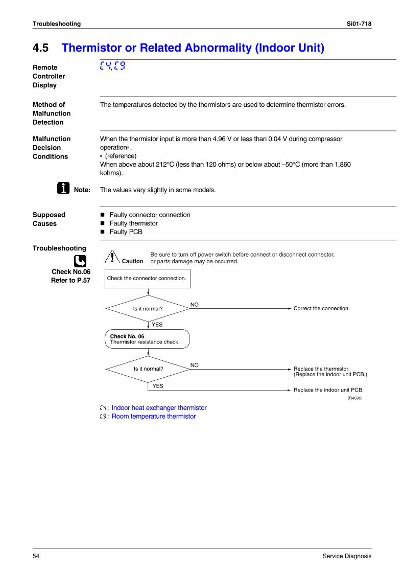
Troubleshooting Si01-718
4.5 Thermistor or Related Abnormality (Indoor Unit)
Remote Controller Display
C4, C9
Method of Malfunction Detection
The temperatures detected by the thermistors are used to determine thermistor errors.
Malfunction Decision Conditions
When the thermistor input is more than 4.96 V or less than 0.04 V during compressor operation∗.∗ (reference)When above about 212°C (less than 120 ohms) or below about –50°C (more than 1,860 kohms).
Note: The values vary slightly in some models.
Supposed Causes
Faulty connector connectionFaulty thermistorFaulty PCB
Troubleshooting
Check No.06Refer to P.57
C4 : Indoor heat exchanger thermistorC9 : Room temperature thermistor
Check the connector connection.
YES
Correct the connection.
Replace the thermistor.(Replace the indoor unit PCB.)
Replace the indoor unit PCB.
Is it normal?
Is it normal?
(R4696)
NO
Check No. 06Thermistor resistance check
YES
NO
CautionBe sure to turn off power switch before connect or disconnect connector, or parts damage may be occurred.
54 Service Diagnosis

Si01-718 Troubleshooting
4.6 Indoor Unit PCB Abnormality
Remote Controller Display
∗
Method of Malfunction Detection
The proper programme operation of the microcomputer is checked by the programme.
Malfunction Decision Conditions
When the microcomputer programme does not function properly.
Supposed Causes
Microcomputer programme is in abnormal condition due to an external factor.*Noise*Momentary voltage drop.*Momentary power failure, etc.Faulty indoor unit PCB.
Troubleshooting
Turn on the power again.
YES
Replace the indoor unit PCB.
Provide proper grounding.
The malfunction may be caused by an external factor, rather than defective parts. Locate the cause of the noise, etc., and correct the situation.
Does the same LED indication appear
again?
Is the grounding proper?
(R1881)
NO
Check the grounding. (earth)
YES
NO
CautionBe sure to turn off power switch before connect or disconnect connector, or parts damage may be occurred.
Service Diagnosis 55

Check Si01-718
5. Check5.1 How to Check5.1.1 Fan Motor Connector Output Check
Check No.01 1. Check connector connection.2. Check motor power supply voltage output (pins 4-7).3. Check motor control voltage (pins 4-3).4. Check rotation command voltage output (pins 4-2).5. Check rotation pulse input (pins 4-1).
7654321
Motor power supply voltageUnusedUnusedP.0V (reference potential)Motor control voltage (15 VDC)Rotation command voltage (1~ 6 VDC)Rotation pulse input
S1
(R3199)
56 Service Diagnosis

Si01-718 Check
5.1.2 Thermistor Resistance Check
Check No.06 Remove the connectors of the thermistors on the PCB, and measure the resistance of each thermistor using tester.The relationship between normal temperature and resistance is shown in the graph and the table below.
Thermistor R25°C=20kΩ B=3950
Temperature (°C)
–20 211.0 (kΩ)
–15 150
–10 116.5
–5 88
0 67.2
5 51.9
10 40
15 31.8
20 25
25 20
30 16
35 13
40 10.6
45 8.7
50 7.2
Service Diagnosis 57

Check Si01-718
58 Service Diagnosis

Si01-718
Removal Procedure 59
Part 7Removal Procedure
1. FT50/60FVM .........................................................................................601.1 Removal of Air Filter / Front Panel .........................................................601.2 Removal of Front Grille ..........................................................................631.3 Removal of Horizontal Blades / Vertical Blades .....................................651.4 Removal of Electrical Box / PCB / Swing Motor .....................................671.5 Removal of Heat Exchanger ..................................................................731.6 Removal of Fan Rotor / Fan Motor.........................................................76
2. R50/60BV1, R60BVL, R50/60CV1A .....................................................782.1 Removal of Panels .................................................................................782.2 Removal of Electrical Box ......................................................................792.3 Removal of Compressor.........................................................................82
Note:The removal procedures for R50BVL are not described.

FT50/60FVM Si01-718
1. FT50/60FVM1.1 Removal of Air Filter / Front Panel
Procedure Warning Be sure to wait 10 minutes or more after turning off all power supplies before disassembling work.
Step Procedure Points
1. Features
When the signal receiver catches a signal from the remote controller, it produces beep sound and the operation lamp blinks.
2. Remove the air filters.1 Hold the front panel by
the tabs on the both sides and lift it until it stops with a click.
2 Lift an air filter upwards slightly by the center knob, and then pull it out downwards.
The right and left filters are interchangeable.Insert the air filters along grooves when installing.Set the air filters with displaying “FRONT” on the front side.Insert 2 hooks of the air filter completely.
Room temperature sensor(thermistor)
(R6699)
ON/OFF
Operation lamp
Signal receiver
Timer lamp
ON/OFF switch
Room temperature sensor(thermistor)
(R6700)
(R6701)
Front panel
Air filter
(R6702)
60 Removal Procedure

Si01-718 FT50/60FVM
3. Remove an “titanium apatite photocatalytic air purifying filter”.
1 Push up the bottom of an air purifying filter to undo the hooks (2 on lower, 3 on upper) and take the filter out.
The right and left filters are interchangeable.
Step Procedure Points
Removal Procedure 61
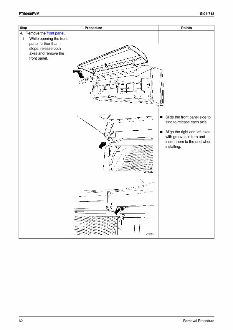
FT50/60FVM Si01-718
4. Remove the front panel.1 While opening the front
panel further than it stops, release both axes and remove the front panel.
Slide the front panel side to side to release each axis.
Align the right and left axes with grooves in turn and insert them to the end when installing.
Step Procedure Points
62 Removal Procedure

Si01-718 FT50/60FVM
1.2 Removal of Front Grille
Procedure Warning Be sure to wait 10 minutes or more after turning off all power supplies before disassembling work.
Step Procedure Points
1. Remove the service cover.
1 Loosen the screw and remove the service cover by the knob.
No field setting switch is inside it. You can remove the front grille without detaching the service cover.
2. Remove the front grille.1 Loosen the 3 fixing
screws of the front grille.
It has no fixing screws inside blades, though previous models had.
Removal Procedure 63
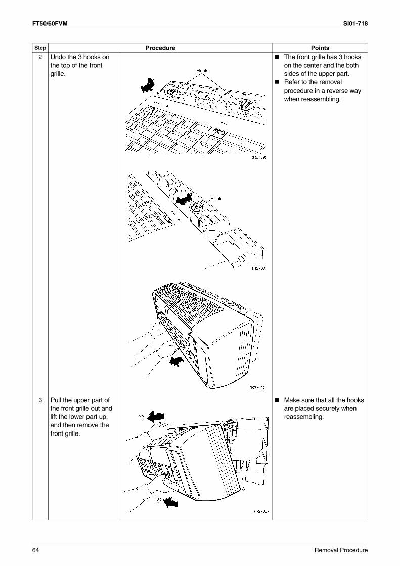
FT50/60FVM Si01-718
2 Undo the 3 hooks on the top of the front grille.
The front grille has 3 hooks on the center and the both sides of the upper part.Refer to the removal procedure in a reverse way when reassembling.
3 Pull the upper part of the front grille out and lift the lower part up, and then remove the front grille.
Make sure that all the hooks are placed securely when reassembling.
Step Procedure Points
64 Removal Procedure

Si01-718 FT50/60FVM
1.3 Removal of Horizontal Blades / Vertical Blades
Procedure Warning Be sure to wait 10 minutes or more after turning off all power supplies before disassembling work.
Step Procedure Points
1. Remove the horizontal blades.
1 Open the horizontal blades.
It has no fixing screws inside blades, though previous models had.
2 Undo the left pivot of the horizontal blades.
3 Bend the horizontal blades slightly and release the center pivots. Slide the horizontal blades to the left and release the right pivot.
Installation procedure1. Since key pattern hook is
provided, rotate the blades and fit it to the right pivot first.
2. Fit the blades to the center and left pivots.
Horizontal blades
(R6703)
Left pivot
(R6704)
Removal Procedure 65

FT50/60FVM Si01-718
2. Remove the vertical blades.
1 Undo the right and left pivots.
2 Undo the 3 hooks.
3 Pull the vertical blades rightwards and remove it.
Step Procedure Points
(R6706)
66 Removal Procedure

Si01-718 FT50/60FVM
1.4 Removal of Electrical Box / PCB / Swing Motor
Procedure Warning Be sure to wait 10 minutes or more after turning off all power supplies before disassembling work.
Step Procedure Points
1. Remove the front grille.Parts layout
2. Remove the drip proof plate.
1 Loosen the screw.
2 Cut the clamp.
3. Disconnect the indoor heat exchanger thermistor and the earth.
Mind that not to lose the clip for the thermistor.
(R6707)
Indoor heat exchanger thermistor
Earth (R6708)
Removal Procedure 67
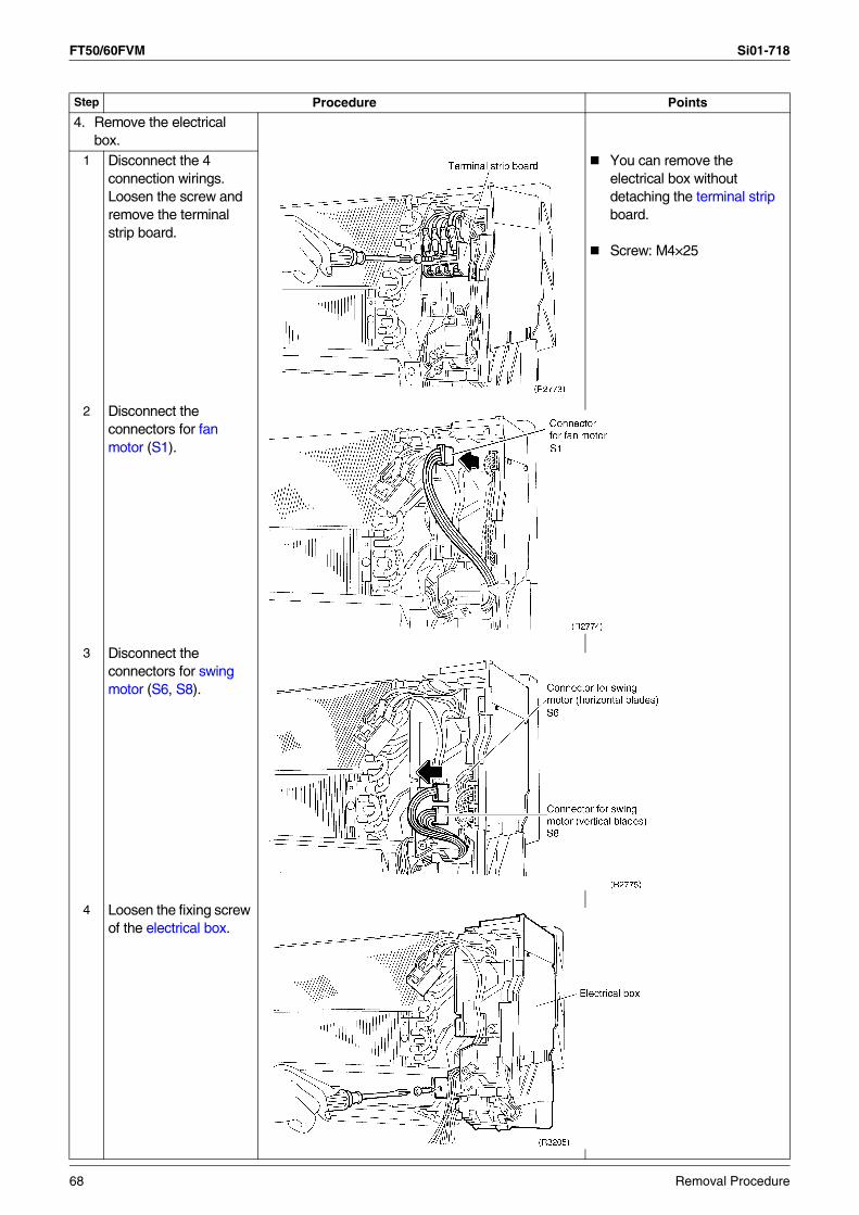
FT50/60FVM Si01-718
4. Remove the electrical box.
1 Disconnect the 4 connection wirings. Loosen the screw and remove the terminal strip board.
You can remove the electrical box without detaching the terminal strip board.
Screw: M4×25
2 Disconnect the connectors for fan motor (S1).
3 Disconnect the connectors for swing motor (S6, S8).
4 Loosen the fixing screw of the electrical box.
Step Procedure Points
68 Removal Procedure

Si01-718 FT50/60FVM
5 Dislocate the electrical box to the left and undo the back hook.
The electrical box has a hook on its back.
6 Pull the electrical box out towards you.
Catch the back hook of the electrical box when reassembling.
7 Loosen the screw on the electrical box.
Screw: M4×16
8 Push the shelter up and undo the hook.
Step Procedure Points
Removal Procedure 69

FT50/60FVM Si01-718
9 Press the receiver units down and undo the hooks on the upper side, and then undo the hooks on the lower side.
Release the hooks on the upper side.
10 Cut the clamp.
11 The receiver units contain 4 PCBs.Remove each PCB with releasing hooks.Disconnect every connector from each PCB.
Remove the receiver units while pushing the hooks of connectors.
12 Cut the clamp. Clamps should be always available. Fix it as it was before.
Step Procedure Points
70 Removal Procedure

Si01-718 FT50/60FVM
5. Remove the control PCB.1 Undo the 2 hooks on
the lower side, and then the 2 hooks on the upper side. Remove the control PCB.
2 Control PCB (indoor unit)S1: connector for the
fan motorS21: HAS26: connector for
buzzer PCB thermistor
S28: connector for signal receiver PCB
S32: connector for the heat exchanger thermistor
6. Remove the swing motor for horizontal blades.
1 Remove the screw of the swing motor.
Step Procedure Points
Removal Procedure 71

FT50/60FVM Si01-718
7. Remove the swing motor for vertical blades.
1 Release the swing axis on the right side.
Releasing the swing axis
2 Loosen the 2 screws and detach the swing motor assembly.
3 Loosen the 2 screws and remove the swing motor.
6 hooks hold the assembly.
Step Procedure Points
72 Removal Procedure

Si01-718 FT50/60FVM
1.5 Removal of Heat Exchanger
Procedure Warning Be sure to wait 10 minutes or more after turning off all power supplies before disassembling work.
Step Procedure Points
Remove the electrical box. Caution
If gas leaks, repair the spot of leaking, then collect all refrigerant from the unit. After conducting vacuum drying, recharge proper amount of refrigerant.
CautionDo not contaminate any gas (including air) other than the specified refrigerant (R-22 or R-410A, depending on the model) into refrigerant cycle.(Contaminating of air or other gas causes abnormal high pressure in refrigerating cycle, and this results in pipe breakage or personal injuries.)
Pay attention so that the residual water in the drain will not make the floor wet.In case that a drain hose is buried inside a wall, remove it after the drain hose in the wall is pulled out.
1. Disconnect the refrigerant piping.
1 Hold the indoor unit up by a piece of wood etc.
2 Unscrew the flare nut for gas piping by 2 wrenches.
Use 2 wrenches to disconnected pipes.When disconnecting pipes, cover every nozzle with caps so as not to let dust and moisture in.
3 Unscrew the flare nut for liquid piping by 2 wrenches.
Removal Procedure 73
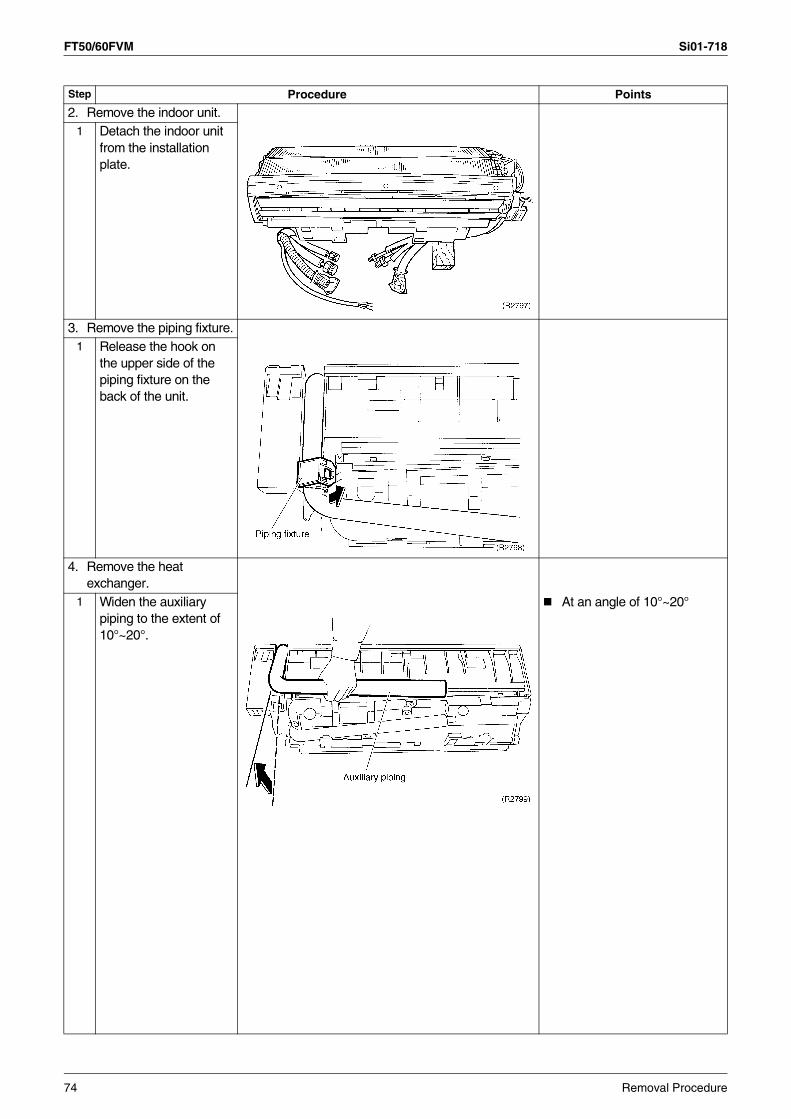
FT50/60FVM Si01-718
2. Remove the indoor unit.1 Detach the indoor unit
from the installation plate.
3. Remove the piping fixture.1 Release the hook on
the upper side of the piping fixture on the back of the unit.
4. Remove the heat exchanger.
1 Widen the auxiliary piping to the extent of 10°~20°.
At an angle of 10°~20°
Step Procedure Points
74 Removal Procedure

Si01-718 FT50/60FVM
2 Release the hooks on the left side.
3 Push the fixing hooks on the right side and release.
4 Pull the heat exchanger to the front side and undo the hooks completely, and then lift it.
CautionWhen removing or reinstalling heat exchanger, be sure to wear protective gloves or wrap the heat exchanger with cloths. (Fins can cut fingers.)
Step Procedure Points
Removal Procedure 75

FT50/60FVM Si01-718
1.6 Removal of Fan Rotor / Fan Motor
Procedure Warning Be sure to wait 10 minutes or more after turning off all power supplies before disassembling work.
Step Procedure Points
1. Remove the right side panel.1 Loosen the 2 screws. You can remove the fan
rotor without detaching the right side panel.
2 Lift the right side panel and remove it.
2. Remove the fan rotor.1 Loosen the screw and
remove the fan motor fixture.
2 Loosen the fixing screw of the fan rotor.
76 Removal Procedure

Si01-718 FT50/60FVM
3. Remove the fan motor.1 Remove the fan rotor. Reassembling the fan motor
(1) When reassembling the fan rotor, provide as much as 5mm of play between the side face of the rotor and the bottom frame.
(2) When reassembling the fan motor, align the end of the connector with the height of
for play.
4. Remove the bearing.1 Remove the fan rotor.
The bearing is on the left side.
2 Loosen the 2 screws and remove the mounting plate for the bearing.
3 The bearing is made of rubber. Push it inwards firmly and remove it.
Step Procedure Points
5mm
Side face ofbottom frameSide face of rotor
(R2808)
Removal Procedure 77
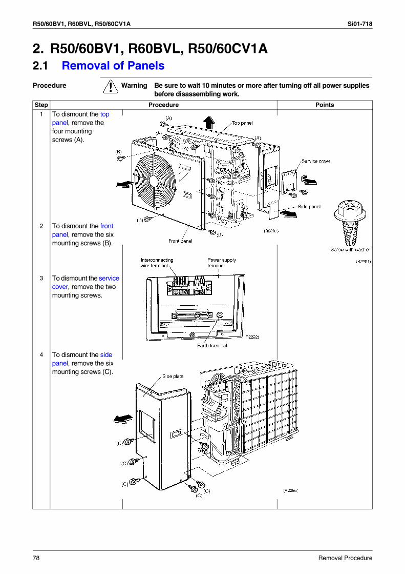
R50/60BV1, R60BVL, R50/60CV1A Si01-718
2. R50/60BV1, R60BVL, R50/60CV1A2.1 Removal of Panels
Procedure Warning Be sure to wait 10 minutes or more after turning off all power supplies before disassembling work.
Step Procedure Points
1 To dismount the top panel, remove thefour mountingscrews (A).
2 To dismount the front panel, remove the six mounting screws (B).
3 To dismount the service cover, remove the two mounting screws.
4 To dismount the side panel, remove the six mounting screws (C).
78 Removal Procedure

Si01-718 R50/60BV1, R60BVL, R50/60CV1A
2.2 Removal of Electrical Box
Procedure Warning Be sure to wait 10 minutes or more after turning off all power supplies before disassembling work.
Step Procedure Points
1 Remove the wire harness connectors from the PCB.
2 Dismount the outdoor air thermistor and the heat exchanger thermistor.
Removal Procedure 79
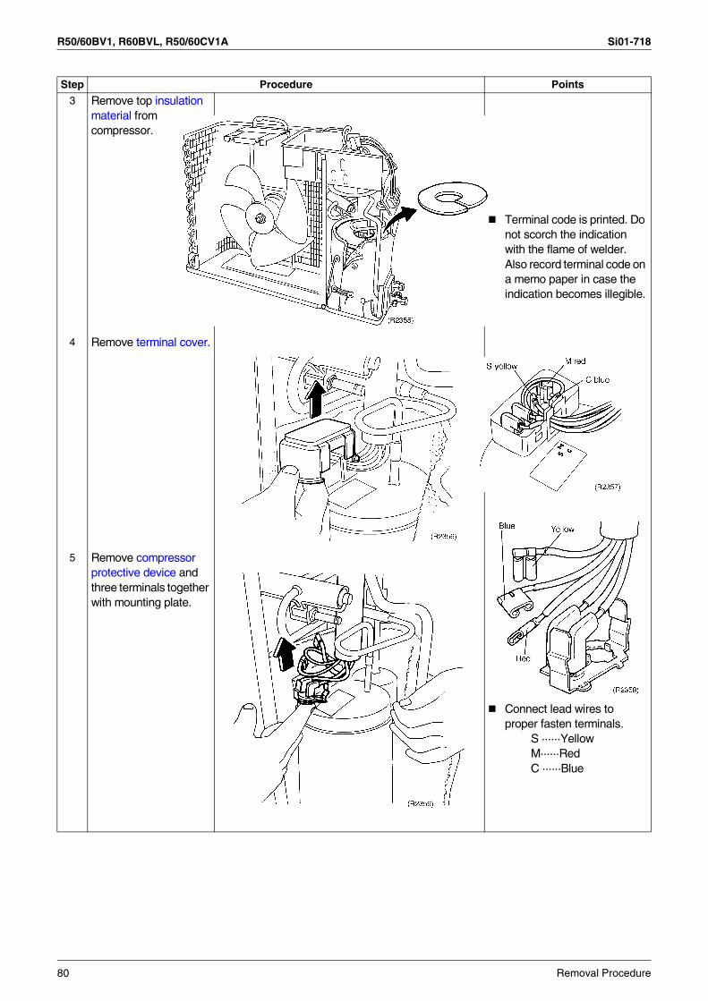
R50/60BV1, R60BVL, R50/60CV1A Si01-718
Step Procedure Points
3 Remove top insulation material from compressor.
Terminal code is printed. Do not scorch the indication with the flame of welder. Also record terminal code on a memo paper in case the indication becomes illegible.
4 Remove terminal cover.
Connect lead wires to proper fasten terminals.
S ······YellowM······RedC ······Blue
5 Remove compressor protective device and three terminals together with mounting plate.
80 Removal Procedure

Si01-718 R50/60BV1, R60BVL, R50/60CV1A
6 Remove the screw.
7 Take off the electrical box.
Step Procedure Points
Removal Procedure 81

R50/60BV1, R60BVL, R50/60CV1A Si01-718
2.3 Removal of Compressor
Procedure Warning Be sure to wait 10 minutes or more after turning off all power supplies before disassembling work.
Step Procedure Points
Make sure that there is no refrigerant in the unit before disassembling.
WARNINGIf refrigerant gas leaks during servicing work, ventilate the area. (If refrigerant gas contacts flames, hazardous gas can generate.)
When removing sound blanket, do not pull it with excessive force, since it is inserted between pipes.
1 Pull out sound blanket (side insulation) from right side.
2 Disconnect suction pipe and discharge pipe of compressor at brazed sections.
82 Removal Procedure

Si01-718 R50/60BV1, R60BVL, R50/60CV1A
3 After disconnecting refrigerant pipes, remove three washer nuts that secure compressor in place. Use open-end wrench to remove washer nut (a) located on right front side.
4 Use T-handle box wrench to loosen nuts (b) and (c).
Step Procedure Points
Removal Procedure 83

R50/60BV1, R60BVL, R50/60CV1A Si01-718
84 Removal Procedure

Si01-718
Others 85
Part 8Others
1. Others ...................................................................................................861.1 Test Run from the Remote Controller ....................................................861.2 Jumper Settings .....................................................................................87
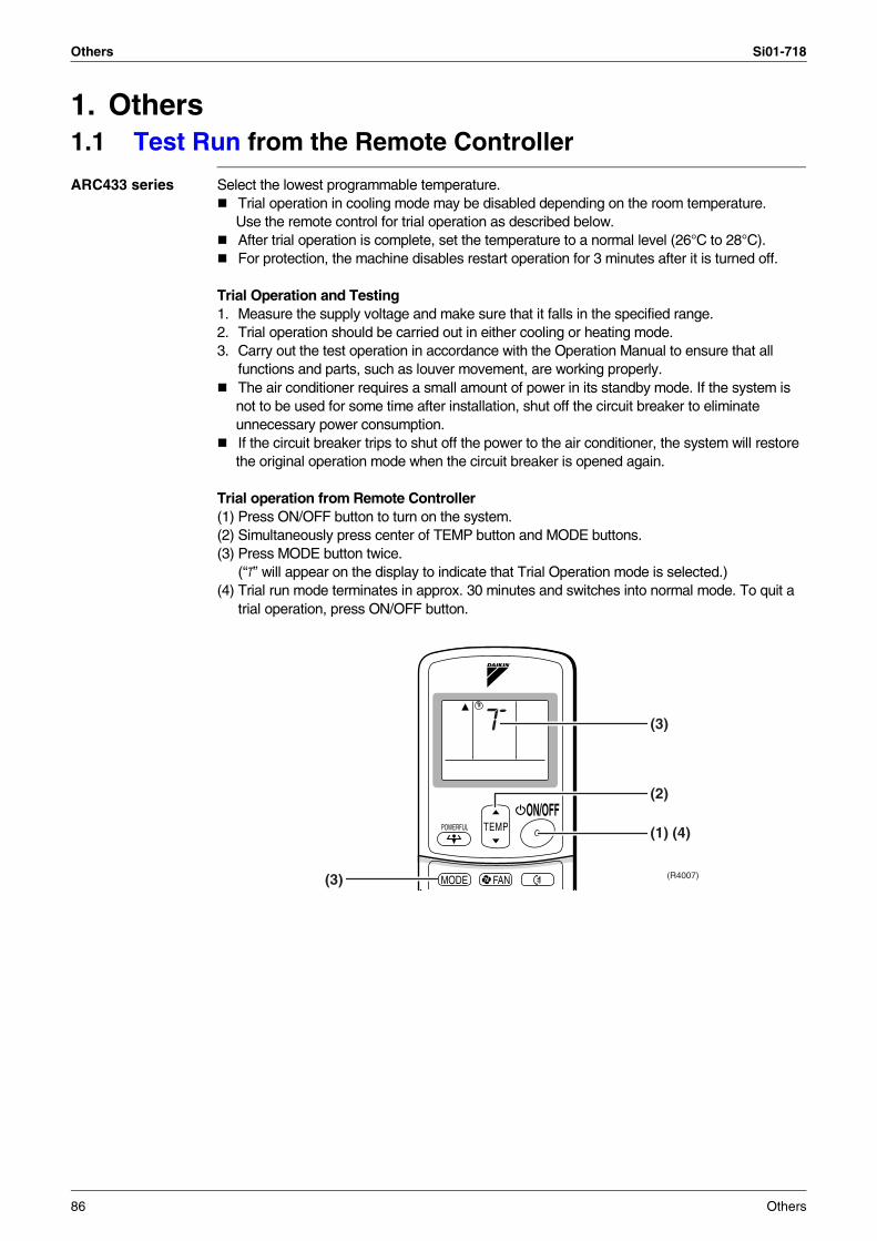
Others Si01-718
1. Others1.1 Test Run from the Remote Controller
ARC433 series Select the lowest programmable temperature.Trial operation in cooling mode may be disabled depending on the room temperature. Use the remote control for trial operation as described below.After trial operation is complete, set the temperature to a normal level (26°C to 28°C).For protection, the machine disables restart operation for 3 minutes after it is turned off.
Trial Operation and Testing1. Measure the supply voltage and make sure that it falls in the specified range.2. Trial operation should be carried out in either cooling or heating mode.3. Carry out the test operation in accordance with the Operation Manual to ensure that all
functions and parts, such as louver movement, are working properly.The air conditioner requires a small amount of power in its standby mode. If the system is not to be used for some time after installation, shut off the circuit breaker to eliminate unnecessary power consumption.If the circuit breaker trips to shut off the power to the air conditioner, the system will restore the original operation mode when the circuit breaker is opened again.
Trial operation from Remote Controller(1) Press ON/OFF button to turn on the system.(2) Simultaneously press center of TEMP button and MODE buttons.(3) Press MODE button twice.
(“T” will appear on the display to indicate that Trial Operation mode is selected.)(4) Trial run mode terminates in approx. 30 minutes and switches into normal mode. To quit a
trial operation, press ON/OFF button.
TEMPON/OFF
POWERFUL
MODE FAN
(2)
(1) (4)
(3)
(3) (R4007)
86 Others

Si01-718 Others
1.2 Jumper Settings1.2.1 When Two Units are Installed in One Room
When two indoor units are installed in one room, the two wireless remote controllers can be set for different addresses.
How to set the different addressesControl PCB of the indoor unit
(1) Remove the electrical box.(2) Cut the address jumper JA on the control PCB.
Wireless remote controller(1) Slide the front cover and take it off.(2) Cut the address jumper J4.
1.2.2 Jumper Setting
(R4417)
ADDR
ESS
JA
ADDRESSJAEXIST 1CUT 2
ADDRESSJ4EXIST CUT
12
J4
(R4418)
Jumper (On indoor control PCB)
Function When connected (factory set)
When cut
JC Power failure recovery function
Auto re-start Unit does not resume operation after recovering from a power failure. Timer ON-OFF settings are cleared.
JB Fan speed setting when compressor is OFF on thermostat.(effective only at cooling operation)
Fan speed setting ; Remote controller setting
Fan rpm is set to “0” <Fan stop>
Others 87

Others Si01-718
88 Others

Si01-718
Appendix 89
Part 9Appendix
1. Piping Diagrams....................................................................................901.1 Indoor Units ............................................................................................901.2 Outdoor Units .........................................................................................90
2. Wiring Diagrams....................................................................................912.1 Indoor Units ............................................................................................912.2 Outdoor Units .........................................................................................92

Piping Diagrams Si01-718
1. Piping Diagrams1.1 Indoor UnitsFT50FVM, FT60FVM
1.2 Outdoor Units
(15.9CuT)
FIELD PIPING
FIELD PIPING
(6.4CuT)
CROSS FLOW FAN
FAN MOTOR
(7.9CuT)
INDOOR UNIT
(12.7CuT)
M
HEAT EXCHANGER
REFRIGERANT FLOW
ON HEAT EXCH.THERMISTOR
COOLING
4D050919E
R50BV1, R60BV1, R50BVL, R50CV1A, R60CV1A R60BVL
OUTDOOR UNIT
COMPRESSOR
PROPELLER FAN
HEAT EXCHANGER
ACCUMULATOR
M
CAPILLARY TUBE
REFRIGERANT FLOWCOOLING
GAS STOP VALVEWITH SERVICE PORT
LIQUID STOPVALVE
FIELD PIPING(15.9CuT)
FIELD PIPING(6.4CuT)
DW521-856N
OUTDOOR UNIT
COMPRESSOR
HEAT EXCHANGER
PROPELLER FAN
HPV
M
ACCUMULATOR
CAPILLARY TUBE
REFRIGERANT FLOWCOOLING
GAS STOP VALVEWITH SERVICE PORT
LIQUID STOPVALVE
FIELD PIPING(6.4CuT)
FIELD PIPING(15.9CuT)
DW527-236D
90 Appendix
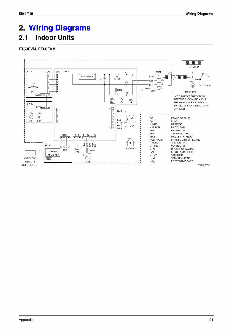
Si01-718 Wiring Diagrams
2. Wiring Diagrams2.1 Indoor Units
FT50FVM, FT60FVM
CONTROLLER
WIRELESSREMOTE
PCB4
PCB3
LED1
H1P
R1T
t°
S37
S38
LED2
H2P
S27
PCB2
RECEIVER
S1W
SIGNAL
S21
S26
S29
S28
PCB1
R2T
S32
t°
~RECTIFIER
1
M1S
RED
M
S6
ORG
YLW
~
PNK
5
BLU
V1
7
1
SA1
S1
3.15AFu
MR2
WHT
BRN
RED
BLU
ORG
V2
H2
H3
H1
INDOOR
FG
M1F
M
GRN
WHT
BLK
/
RED
FG : FRAME GROUNDFu : FUSE H1~H3 : HARNESS H1P, H2P : PILOT LAMP M1F : FAN MOTOR
S1W : OPERATION SWITCH
MR2 : MAGNETTIC RELAY
SA1
M1S
PCB1~PCB4 : PRINTED CIRCUIT BOARDR1T, R2T : THERMISTORS1~S38 : CONNECTOR
YLW
V1, V2 : VARISTOR X1M : TERMINAL STRIP
X1M
3
2
1
: SWING MOTOR
: SURGE ARRESTER
: PROTECTIVE EARTH
NOTE THAT OPERATION WILLRESTART AUTOMATICALLY IFTHE MAIN POWER SUPPLY ISTURNED OFF AND THEN BACKON AGAIN.
FIELD WIRING.
CAUTION
2
3
1
OUTDOOR
3D038655E
Appendix 91

Wiring Diagrams Si01-718
2.2 Outdoor Units
R50BV1
R60BV1
L : LIVE
C11R, C12R : RUNNING CAPACITORF1U : FUSEF1S : SURGE ARRESTERK1M : COMPRESSOR RELAY
M1C : COMPRESSOR MOTOR
TO INDOOR UNIT
POWER SUPPLY
X1M
N
L
3
2
1
BLK
N : NEUTRALQ1L : OVERLOAD PROTECTOR
M1F : FAN MOTOR
X1M : TERMINAL STRIPX11A : CONNECTOR
RED
RED
F1S
BLK
BLK
3.15A
F1U
WHT
RED
RED
BLK
Q1L
13
A1
5
1
OR
G K1M
NOTES1. REFER TO THE NAMEPLATE FOR
A2
14
6
2
THE POWER REQUIREMENTS.
RED
RED
C12R
C11R
BLU
WHT
BLK
RED
YLW
RED
X11A
S
M
C
1~
1~
M
M
M1F
M1C
3D040743A
L
C11R, C12R
F1UF1S
K1M
M1C
TO INDOOR UNIT
POWER SUPPLY
X1M
L
N
2
3
1
BLK
NM1F
S1T
X1M X11A
RED
RED
F1S
BLK
BLK
3.15A
F1U
WHT
RED
RED
BLK 13
A1
5
1
NOTES1.REFER TO THE NAMEPLATE FOR
K1M
THE POWER REQUIREMENTS.
14
2
6
A2 RED
RED
C11R
WHT
C12R
C
H
LS1T
L
H
YLW
WHT
RED
BLU
RED
BLK
ORG
X11A
S
C
R
1~
1~M
M
M1F
M1C
: RUNNING CAPACITOR: SURGE ARRESTER: FUSE: COMPRESSOR RELAY: LIVE: COMPRESSOR MOTOR
: FAN MOTOR: NEUTRAL: THERMOSTAT: CONNECTOR: TERMINAL STRIP
3D032200A
92 Appendix

Si01-718 Wiring Diagrams
R50BVL
R60BVL
TO INDOOR UNIT
POWER SUPPLY
X1M
N
L
2
3
1
F1S
3.15A
F1U
Q1L
13
A1
5
1
K1M
A2
14
2
6
C12R
C11R
X11A
S
M
CM1~
M1~
M1F
M1C
C11R, C12R : RUNNING CAPACITORF1U : FUSEF1S : SURGE ARRESTERK1M : COMPRESSOR RELAYL : LIVEM1C : COMPRESSOR MOTOR
M1F : FAN MOTORN : NEUTRALQ1L : OVERLOAD PROTECTORX11A : CONNECTORX1M : TERMINAL STRIP
NOTES1.REFER TO THE NAMEPLATE FOR
THE POWER REQUIREMENTS.
RED
RED
BLK
BLU
YLW
BLK
WHT
RED
RED
BLK
RED
RED
BLK
BLK
WHT
RED
RED
BLK
OR
G
3D032199B
POWER SUPPLY~220V 60Hz
FIELD WIRING.
INDOOR
LN
F1S
K1MF1U
C11R,C12R
: FUSE
: LIVE: COMPRESSOR RELAY
: SURGE ARRESTER:RUNNING CAPACITOR
: NEUTRAL
X1M
2
3
N
L
1
BLK
RED
RED
BLK
F1S
BLK
3.15A
X1M
M1FQ1L
S1T
F1U
X11A
M1C
WHT
RED
RED
: CONNECTOR
: FAN MOTOR
: TERMINAL STRIP
: COMPRESSOR MOTOR: THERMOSTAT
: OVERLOAD PROTECTOR
BLK
Q1L
13
A1
ORG
5
1
K1M
14
2
6
A2
PROTECTIVE EARTH
RED
RED
C11R
WHT
C12R
NOTE
C
H
L
BLU
THE POWER REQUIREMENTS.REFER TO THE NAMEPLATE FOR
S1T
L
H
YLW
BLK
WHT
RED
ORG
RED
X11A
BLK
WHT
ORG
RED
S
C
M
1 ~
1 ~M
M
OUTDOOR
M1F
M1C
3D032198C
Appendix 93

Wiring Diagrams Si01-718
R50CV1A
R60CV1A
3
2
1
FIELD WIRING.
N
L
: SURGE ARRESTERF1S
N
L
K1M : COMPRESSOR RELAY
M1C
C11R, C12R : RUNNING CAPACITOR
indoor
outdoor
X1MF1U : FUSE
3.15A
5
RED
F1U
GRN
M
YLW
C11R
N
A2
F1S
X11A: TERMINAL STRIP
GRN
OR
G
RED
WHT
RED
S
BLK M1F
C
X1M
1
6
POWER SUPPLY
3
RED
13
: OVERLOAD PROTECTOR
BLK
YLW
BLU
RED
BLK
M
: FAN MOTOR
: CONNECTOR
M1F: NEUTRAL
YLW
: LIVE
BLK
X11AK1M
: PROTECTIVE EARTH
~50Hz 220-240V
M1C
1
RED
M
BLK
2
THE POWER REQUIREMENTS.1.REFER TO THE NAMEPLATE FOR
NOTES
L
Q1L
C12R
14
Q1L
2
RED
: COMPRESSOR MOTOR
REDA1WHT
/
/
~
~
3D045730A
1
3
2
outdoor
: RUNNING CAPACITORC11R, C12R
F1U : FUSE
indoor
L
X1M
F1S : SURGE ARRESTER
: COMPRESSOR RELAYK1M
M1C
N
L
N
FIELD WIRING.
2
A2
BLK
NOTES1. REFER TO THE NAMEPLATE FOR
THE POWER REQUIREMENTS.
X11A
: COMPRESSOR MOTOR
5
N
/
RED WHT
6
K1M
X1M
YLW
RED
GRN
RED
HL
M1F
3
YLW
RED
/
: TERMINAL STRIP
14
: NEUTRAL
L
S
1
RED
: PROTECTIVE EARTH
L
GRN
2
~50Hz 220-240V
F1U
BLK
C
WHT
13
S1T
WHT
BLK
C11R
S1T
M1CRED
RED
F1S
1
BLK
X11A
R
ORGH
M1F
3.15A
C
C12R
: FAN MOTOR
BLK M
BLU
A1
YLW
: CONNECTOR
POWER SUPPLY: LIVE
M
: THERMOSTAT
RED
~
~
3D045733
94 Appendix

Si01-718
Index
Numerics00 ...........................................................................493 minutes stand-by .................................................20
AA1 ...........................................................................50A5 ...........................................................................51A6 ...........................................................................52address setting jumper ...........................................10air filter ...................................................................60ARC433A ...............................................................46auto-restart .............................................................87auto-restart function ...............................................20auto-swing ..............................................................14
Bbuzzer PCB ............................................................11
CC4 ...........................................................................54C9 ...........................................................................54centralized control ..................................................10check
fan motor connector output check ...................56thermistor resistance check .............................57
check No.01 ...........................................................56check No.06 ...........................................................57compressor ............................................................82compressor protective device ................................80connectors ..............................................................10control PCB (indoor unit) ............................11, 50, 71
Ddiagnosis mode ......................................................47discharge pipe ........................................................82display PCB ............................................................11drain hose ..............................................................73drip proof plate .......................................................67
Eearth .......................................................................67electrical box ....................................................68, 79error codes
00 .....................................................................49A1 ....................................................................50A5 ....................................................................51A6 ....................................................................52C4 ....................................................................54C9 ....................................................................54
error codes and description ....................................49
Ffan motor ..........................................................68, 76fan motor connector output check ..........................56fan motor or related abnormality ............................52
fan rotor ................................................................. 76fan speed control ................................................... 15fan speed setting ............................................. 10, 87filter
mold proof air filter (prefilter) ........................... 20titanium apatite photocatalytic air-purifying
filter .................................................... 20freeze-up protection control .................................. 51front grille .............................................................. 63front panel ....................................................... 62, 78FU1 ....................................................................... 10fuse ....................................................................... 10
Ggas piping .............................................................. 73
HH1 .......................................................................... 10H2 .......................................................................... 10H3 .......................................................................... 10HA ................................................................... 10, 71Hall IC ............................................................. 15, 52heat exchanger ..................................................... 73horizontal blade ..................................................... 65
Iindoor heat exchanger thermistor ................... 54, 67indoor unit PCB abnormality ........................... 50, 55instructions ............................................................ 23insulation material ................................................. 80
JJ4 .......................................................................... 87JA .................................................................... 10, 87JB .................................................................... 10, 87JC .................................................................... 10, 87jumper settings ...................................................... 87
LLED A .................................................................... 10LED1 ..................................................................... 10LED2 ..................................................................... 10liquid piping ........................................................... 73list of functions ........................................................ 2
Mmain functions ....................................................... 14mold proof air filter (prefilter) ................................. 20
Nnight set mode ....................................................... 18
OON/OFF button on indoor unit ............................... 20operation lamp ...................................................... 44
Index i

Si01-718
outdoor air thermistor .............................................79outdoor heat exchanger thermistor ........................79
Ppiping diagrams ......................................................90power failure recovery function ........................10, 87power-airflow dual flaps .........................................14POWERFUL operation ...........................................19printed circuit board (PCB)
buzzer PCB .....................................................11control PCB (indoor unit) .....................11, 50, 71display PCB .....................................................11signal receiver PCB .........................................11
programme dry function .........................................17
Rreceiver units ..........................................................70remote controller ....................................................46room temperature thermistor ..................................54RTH1 ......................................................................10
SS1 ...............................................................10, 68, 71S21 ...................................................................10, 71S26 ...................................................................10, 71S27 .........................................................................10S28 ...................................................................10, 71S29 .........................................................................10S32 ...................................................................10, 71S37 .........................................................................10S38 .........................................................................10S6 .....................................................................10, 68S8 .....................................................................10, 68safety precautions ..................................................23self-diagnosis digital display ...................................20service check function ............................................46service cover ....................................................63, 78shelter ....................................................................69side panel ...............................................................78signal receiver ........................................................60signal receiver PCB ................................................11signal receiving sign ...............................................20sound blanket .........................................................82specifications ............................................................6suction pipe ............................................................82SW1 .......................................................................10swing motor ................................................68, 71, 72swing motor assembly ............................................72
Tterminal cover .........................................................80terminal strip .....................................................50, 68test run ...................................................................86thermistor
indoor heat exchanger thermistor ..............54, 67outdoor air thermistor ......................................79outdoor heat exchanger thermistor ..................79room temperature thermistor ...........................54
thermistor or related abnormality (indoor unit) .......54thermistor resistance check ...................................57thermostat control ..................................................16
titanium apatite photocatalytic air-purifying filter ... 20top panel ............................................................... 78troubleshooting ...................................................... 49troubleshooting by symptoms ............................... 45
VV1 .......................................................................... 10V2 .......................................................................... 10varistor .................................................................. 10vertical blade ......................................................... 66
Wwide-angle louvres ................................................ 14wiring diagrams ..................................................... 91
ii Index

Si01-718
Drawings & Flow Charts iii
Drawings & Flow Charts
Numerics3-D airflow ..............................................................14
AARC433A ...............................................................46auto-swing ..............................................................14
Bbuzzer PCB ............................................................11
Ccheck No.01 ...........................................................56check No.06 ...........................................................57control PCB (indoor unit) ........................................11
Ddiagnosis mode ......................................................47display PCB ............................................................11
Ffan motor connector output check ..........................56fan motor or related abnormality ............................52fan speed control for indoor units ...........................15freeze-up protection control ...................................51
Iindoor unit PCB abnormality ............................50, 55
Jjumper settings .......................................................87
Nnight set mode ........................................................18
OON/OFF button on indoor unit ................................20operation lamp, location .........................................44
Ppiping diagram
FT50FVM .........................................................90FT60FVM .........................................................90indoor units ......................................................90outdoor units ....................................................90R50BV1 ...........................................................90R50BVL ...........................................................90R50CV1A .........................................................90R60BV1 ...........................................................90R60BVL ...........................................................90R60CV1A .........................................................90
POWERFUL operation ...........................................19programme dry function .........................................17
Rremote controller ....................................................46
Ssignal receiver PCB ............................................... 11
Tthermistor or related abnormality (indoor unit) ...... 54thermistor resistance check .................................. 57thermostat control ................................................. 16trial operation from remote controller .................... 86
Wwiring diagram
FT50FVM ........................................................ 91FT60FVM ........................................................ 91indoor units ..................................................... 91outdoor units ................................................... 92R50BV1 .......................................................... 92R50BVL .......................................................... 93R50CV1A ........................................................ 94R60BV1 .......................................................... 92R60BVL .......................................................... 93R60CV1A ........................................................ 94

Specifications, designs and other content appearing in this brochure are current as of March 2007 but subject to change without notice.Si 01-718Printed in Japan 03/2007 B AK


![Connectornewsletter oct%202013[2]](https://static.fdocuments.us/doc/165x107/568c48be1a28ab4916916750/connectornewsletter-oct2020132.jpg)