
SPLIT COUPLED PUMPSfiles.pentairliterature.com/aurora/A-03-369.pdfMETHODOLOGY TO ORIENT PUMPS...
24
NOTE! To the installer: Please make sure you provide this manual to the owner of the equipment or to the responsible party who maintains the system. INSTALLATION OPERATION AND MAINTENANCE INSTRUCTIONS VERTICAL INLINE SPLIT COUPLED PUMPS ENGLISH: PAGES 2-12 Installation Operation and Maintenance Instructions NOTE! To the installer: Please make sure you provide this manual to the owner of the equipment or to the responsible party who maintains the system. Part # A-03-369 | © 2018 Pentair plc. | | 06/06/18 Models Series 382 SC AURORA
Transcript of SPLIT COUPLED PUMPSfiles.pentairliterature.com/aurora/A-03-369.pdfMETHODOLOGY TO ORIENT PUMPS...

NOTE! To the installer: Please make sure you provide this manual to the owner of the equip ment or to the responsible party who maintains the system.
INSTALLATION OPERATION AND MAINTENANCE INSTRUCTIONS
VERTICAL INLINE SPLIT COUPLED PUMPS
ENGLISH: PAGES 2-12Installation Operation and Maintenance Instructions
NOTE! To the installer: Please make sure you provide this manual to the owner of the equipment or to the responsible party who maintains the system.
Part # A-03-369 | © 2018 Pentair plc. | | 06/06/18
Models Series 382 SC
AURORA

IMPORTANT NOTE TO THE INSTALLER:This manual contains important information about the installation, handling, operation and safe use of Pentair vertical in-line pumps. This information should be given to the owner/operator of this equipment. The following instructions must be strictly adhered to get a safe and failure-free operation.
APPLICATIONS:The 382 SC series pumps are superior commercial in-line pumps which have been manufactured and field tested under the severest demands. Pumping applications for the 382 SC include: hot or chilled water circulation, pressure booster systems and cooling towers for office buildings, hotels, hospitals, universities and warehouses.
ATTENTION: SAFETY WARNINGS:Read and understand all the warnings before installation or servicing pump.
• Handling, transportation and installation of this equipment should only be undertaken by trained personnel with proper use of lifting equipment. (Refer lifting arrangements “FIG. 3A & FIG. 3B”)
• Only water or other suitable HVAC media may be circulated through the use of these pumps. Circulation of hazardous, corrosive or flammable liquids by using these pumps is strictly prohibited.
• DO NOT turn on the electrical supply to the pump until all the plumbing connections and commissioning procedure have been accomplished.
• The pump must not be operated dry without fluid. • Pipe systems must be installed in such a manner so
that minimum load is transferred on pump flanges.• Ensure that the motor installation instruction manual
has been followed for determining the proper terminal connections so that correct pump rotation is obtained.
OPERATIONAL LIMITS: *• Maximum operating pressure at temperature 150°F
(65.6°C) is:i. 125# Flanges: 175 PSI ii. Up to 250 PSI dependent on the Mechanical Seal
• Maximum operating temperature: 225°F (107°C) (Standard Seal)
• Pump Speed and Head: Refer the pump nameplate
*See ASTM A126/ANSI B16.1 for pressure/temperature ratings of flanges
NOISE & VIBRATION LEVELS: 382 SC pumps have been designed to meet the noise and vibration levels as per HI standard 9.6.4.
2
ELECTRICAL SAFETY:
Sudden Start-Up HazardDisconnect and lockout power source before servicing. Failure to follow these instructions could result in serious personal injury, death or property damage.
Electrical Shock HazardAll electrical connections are to be made by a qualified electrician in accordance with all codes and ordinances. Failure to follow these instructions could result in serious personal injury, death or property damage.
Electrical Overload HazardInsure all motors have properly sized overload protection. Failure to follow these instructions could result in serious personal injury, death or property damage
HIGH TEMPERATURE SAFETY:
Hot Surface HazardIf pumping hot water, insure guards or proper insulation is installed to protect against skin contact to hot piping or pump components. Failure to follow these instructions could result in serious personal injury, death or property damage.
Spraying Water HazardWhen servicing pump replace all gaskets and seals. Do not re-use old gaskets or seals. Failure to follow these instructions could result in serious personal injury, death or property damage.
HIGH PRESSURE SAFETY:
High Pressure HazardAll single suction pumps are rated at a maximum of 175 psi and double suction pumps are rated at 250 psi. Do not exceed this pressure. Install properly sized pressure relief valves in system. Failure to follow these instructions could result in serious personal injury, death or property damage.
Expansion HazardWater expands when heated. Install properly sized thermal expansion tanks and relief valves. Failure to follow these instructions could result in serious personal injury, death or property damage
CALIFORNIA PROPOSITION 65 WARNING: This product and related accessories contain
chemicals known to the State of California to cause cancer, birth defects or other reproductive harm.

3
PRODUCT DESCRIPTIONCONFIGURATION:Pumps are offered with various Mechanical seal types available.
• Type 1• Type 21• Type 8B2
Along with above mentioned configurations, pumps are also offered with following options required and mentioned by customer at the time of placing order.
• With or without Impeller wear rings (Not applicable for pumps below 10x13.5)
• With or without Flush line• With or without Abrasive separator
PARTS:Refer to Exploded View, FIG. 32, FIG. 33, FIG. 34 & FIG 35 for listing various parts
INSTALLATIONREAD AND UNDERSTAND ALL SAFETY WARNINGS AT THE BEGINNING OF THE MANUAL BEFORE BEGINNING INSTALLATION OR ANY REPAIR WORK.PUMP LOCATION:The pump should be located as close to the liquid source as possible so that the suction line can be short and direct. Location should require a minimum of elbows and fittings in the discharge line to minimize friction losses. The pump must be protected against flooding and located in a clean, open area, where it is easily accessible for inspection, disassembly and repair.
To minimize friction losses pump should be located such that the use of elbows and fittings in the discharge line is reduced. Pumps installed in dark, dirty areas or in cramped locations are often neglected, which can result in premature failure of both the pump and the driver. Open area would also be helpful in better air flow into the motor and/or motor fan.
The 382 SC pump must be installed vertically. Install isolating valves on each side of pump so that pump maintenance can be performed without draining the system. Special mounting requirements may be required.
if the pump is to be mounted near a noise or vibration sensitive area. The installation must be evaluated to ensure that the net positive suction head available (NPSHA) meets or exceeds the net positive suction head required (NPSHR), as stated by the pump performance curve.
STORAGE & PROTECTION:All pumps are shop serviced and delivered in a ready to operate condition. If the pump after being delivered is not put into immediate operation then proper care should be taken so that it operates without failure when put into service. The pump should be kept in a clean and dry area in a vertical position. Ensure that the following precautions are taken for pumps being stored for more than six months.
• Pump surfaces which are machined and unpainted (e.g. flange ends, feet mounting etc.) and are easily subjected to corrosion must be protected by corrosion resistant coating.
• The pump shaft should be rotated once in a month to avoid locking of rotating assembly. This would also be helpful in uniform distribution of lubrication on bearings.
• Bearings must be lubricated with fresh lubricants when pump is being put into service after a long time.
UNCRATING AND LIFTING:Before shipment pump is fastened securely to the crate. The pump should be removed from the crate carefully by using proper tools and equipments. After removing from crate make sure that all the components are in good condition and have been received as mentioned in the packing list. Report immediately to the concerned person/department if any component is missing or received in a damaged condition. Extreme care must be taken while handling the pump set. Slings and hooks should be used in such a manner, so that while lifting the pump is not exposed to stresses.
METHODOLOGY TO ORIENT PUMPS VERTICALLY WHILE UNPACKING THE UNIT. Since the pumps are shipped horizontally laid on crate (shown in FIG.2). It is necessary to orient pumps vertically before shifting to their installation location. Once the unit is uncovered, lift the unit by placing straps around the motor while making a pivot point of casing. Human effort will also be required to orient the unit to vertical position. Now let the unit to rest on crate and follow the procedure mentioned below to place the unit to its desired location.
FIG. 2
FIG. 1

4
NOTE:
For typical installation, suitable overhead lifting equipment of adequate capacity to lift the driver, the entire pump (without driver), or the heaviest sub assembly of the pump should be available at the jobsite when installing or removing the pump.
Use following procedure for lifting the pump set.
i. Remove the coupling guard ii. Size 8x8x13.5 & 10x10x13.5: Use eye bolt or lifting lugs
on motor bracket for lifting the entire unit as shown in the FIG.3A.
With Strap With Spreader Bar
FIG. 3A
iii. For Other Sizes: Place lifting straps/slings on each side of coupling through the motor bracket as shown in the FIG.3B.
iv. Use spreader bar in between the slings if necessary. This would be helpful for protecting the motor fan cover while lifting.
v. DO NOT use eye bolt or lifting lugs on motor and/or motor bracket for lifting the entire unit.
vi. DO NOT place cable slings around the motor shaft.
With Strap With Spreader Bar
FIG.3B
COMMISSIONINGMOUNTING:The pump has been designed to be installed in various configurations as shown in the images below.
1. HANGER SUPPORTED PIPE MOUNTED: (Models 8x8x13.5, 10x10x13.5, 10x10x19, 10x10x14,
12x12x14, 12x12x18, 14x14x15 and 14x14x18 Only) Where floor space is a restriction, 382 SC Vertical Inline
pumps can be installed in the system piping without any additional support from base, as illustrated in FIG.4. For such an installation, care must be taken to ensure that pipe hangers are designed to bear additional weight of pump set.
FIG. 4
2. PIPE MOUNTED SUPPORTED AT CEILING: (Models 8x8x13.5, 10x10x13.5, 10x10x19, 10x10x14,
12x12x14, 12x12x18, 14x14x15 and 14x14x18 Only) In tight rooms pump can be installed directly into the
system piping with no base support and piping can be supported close to ceiling. With this arrangement the pump may be installed with a multi-purpose valve on the discharge side and suction diffuser on the suction side of the pump, as illustrated in FIG.5.
FIG 5.
3. FLOOR SADDLE SUPPORT: (Models 8x8x13.5, 10x10x13.5, 10x10x19, 10x10x14,
12x12x14, 12x12x18, 14x14x15 and 14x14x18 Only)

5
In many of the installation locations where support to pump from above is not possible, floor mounted saddle support can be provided beneath suction and discharge piping. The pump case may be mounted on a base in such an installation but is not necessary. The installation is illustrated in FIG.6.
FIG.6
4. PIPE SUPPORTS: (Models 8x8x13.5, 10x10x13.5, 10x10x19, 10x10x14,
12x12x14, 12x12x18, 14x14x15 and 14x14x18 Only) For ease of installation and increasing rigidity of the
unit, a Structural support may be provided at the pump suction and discharge ports with Isolation pads beneath the support, as illustrated in FIG.7. It is to be ensured that pipe hangers are so adjusted that pump flanges do not support the piping.
FIG.7
5. FLOOR MOUNTED: It is recommended that larger double suction vertical
in-line pumps be floor mounted. This recommendation is based on the account of weight of pump and motor assembly. A mounting base is to be used for floor mounting which can be fastened to the integral cast in feet on the bottom of casing, as illustrated in FIGS.8A and 8B. Make sure that pump is firmly bolted to the mounting base which in turn is also rigidly secured and mounted on the floor. During floor mounting it is
recommended that flexible connectors are used to eliminate the potential for pipe load to be transferred to the pump. If flexible connectors are not used, it is very important to closely monitor the height of the pump support. If the height of support is more than required then the entire pipe load will be transferred to the pump which will start acting like a pipe support.
FIG.8A
FIG.8B
When the pump is floor mounted, the piping will still need to be supported on both the suction and discharge sides to eliminate pipe stress at the pump. For supporting the pump from the bottom, case feet have been drilled and tapped to use commonly available pipe flanges to create the pump support.
PUMP SIZE FEET DRILLING AS PER FLANGE
2x2x7, 2x2x9C 2”
2.5x2.5x7, 3x3x7A & B, 4x4x7A & B, 2.5x2.5x9, 3x4x9, 4x5x9 3”
5x5x9, 6x6x9, 4x4x11, 5x5x11, 6x6x11, 8x8x11, 4x4x12, 5x5x12,
6x6x12, 8x8x12
4”
8x8x13.5, 10x10x13.5 6”
10x10x14, 10x10x19 8”
12x12x14, 12x12x18, 14x14x15, 14x14x18
10”

6
PIPING:A minimum length of straight pipe is required on the suction side of the pump. Five times the pipe diameter is sufficient to allow a smooth entry of liquid into the pump.
Avoid using short elbows as they tend to give higher friction losses and interruption in streamline flow. Suction and discharge piping must be in line. To avoid undue stresses on pump and pipe flanges, never force align the pipes and provide a rigid support near the pump casing. Pump flanges must be tightened evenly to avoid flange cocking and liquid leakage.
Air leak/trapped in suction piping is one of the major cause of erratic pump performance. To avoid any such kind of trouble, suction piping should be arranged in such a manner that there are no high spots. This is to ensure that air is not trapped in the suction line which will cause faulty pump operation. Wherever suction line is larger than the pump suction nozzle, it is mandatory to use an eccentric reducer. For sumps below center line the straight side of the reducer must be located upwards so that any air cavity if present in the suction line passes through the line to outlet and there is no pressure drop at pump suction due to presence of air pockets.
The check valve must be installed in the discharge line which prevents backward flow of liquid into the pump, thereby protecting the pump from liquid back pressure.
Note: The suction valve should be fully open and should not be used for flow regulation. The discharge valve is to be used for flow regulation.
OPERATIONThe following points must be ensured before starting the pump:
i. The current supply agrees with the voltage and frequency on the motor nameplate.
ii. The motor is wired for correct voltage.iii. The thermal overload relays are correct size and set
for operation.iv. The pump is fully primed. Flood the casing and seal
area with liquid to release the air out of pump through flush line and air vent valve near discharge flange. Priming must be continued till air is completely removed. This would be indicated by continuous flow of liquid through flush line and air vent. If accessible, rotate shaft slowly by hand to evacuate air trapped in the impeller passages and to ensure free turning of the pump.a. Failure to flood the seal area with water may
cause seal failure due to lack of lubrication.v. Jog the motor to check that the motor rotates
clockwise, as indicated by the arrow on the pump casing.
vi. Coupling guard must be in its appropriate position on account of human safety.
STARTING UP:NOTE: MAKE SURE SUCTION LINE VALVE IS IN OPEN POSITION AND DISCHARGE LINE VALVE CLOSED
1. Check that the pump is operating smoothly and is not rubbing.
2. Start opening the discharge valve gradually. (Note: Do not run the pump for extended period with
discharge valve closed, so as to avoid overheating and potential damaging loads.)
3. The pump is also provided with a circulation relief valve that prevents overheating when the pump is operating at reduced capacity.
4. Stop the pump immediately if any of the following situations arise: i. No/insufficient liquid. ii. Inadequate discharge pressure. iii. Loss of suction pressure. iv. High power consumption.v. Noisy operation and/or High Vibration. Check the manual for troubleshooting the cause.
SHUT DOWN:It is advisable to close the discharge valve before stopping the pump to avoid any water hammer effect. However, this practice is not mandatory and pump may be stopped with discharge valve open in case an emergency.
Preferred shutdown sequence is as follows:
1. Preferably close the discharge valve first.2. Then turn off the motor.3. Now, close the suction line valve.4. Drain the pump liquid completely, if pump to be kept
un-operational for longer period or if there is danger of freezing.
MAINTENANCE AND SERVICEMAINTENANCE AND SERVICE TO THE PUMPROUTINE CHECK-UP:Preventive maintenance and routine check-ups may prevent the pump from major failures. An inspection & maintenance log should be kept & the inspector is to immediately report any problems. Pump should be checked on regular basis for any unusual noise, vibrations and abnormal rise of temperature. Also, check the sight flow indicator from time to time for fluid flow and if no flow is observed, replace the filter or check the separator. A suggested guide for preventive maintenance for normal application is given below:

7
Items Action required FrequencyVibration Check for change
in vibrationRefer to ANSI/HI 9.6.5
Condition Monitoring
Bolting Check for loose bolting
Annually
Mechanical Seals
Monitor seal leakage
Refer to ANSI/HI 9.6.5 Condition Monitoring
LUBRICATION:The pump does not contain any bearings that require lubrication; however motor bearings must be lubricated periodically. Refer motor manufacturer’s instructions manual for frequency of lubrication and correct amount of lubricant.
SPLIT COUPLINGPower is transmitted from motor shaft to the pump shaft through a split coupling. The pump shaft does not contain bearings that need lubrication.
MECHANICAL SEALThe mechanical seal require flushing which is flushed from discharge of the pump through a flush line. A throttle bush isolates the mechanical seal from the liquid in the pump. Since mechanical seals need a film of liquid between the sealing faces, pump must not be run unless properly filled with liquid for intended operation.
A ‘weep’ sound may be heard from Mechanical seals at start-up. The pump should be made run for approx. 8-10 hours, which is the break-in period for seal. During this operation the mechanical seal would ‘seat’ properly.
The 382 SC pumps are supplied with three basic types of seals
1. Seal type 1 2. Seal type 213. Seal type 8B2
FIG.9 A
Mechanical Seal (Type 1 & 21)
Rotating part
Outboard part
/&-"$*.('$012# (
Impeller End
Stationary part
Gland
Mechanical Seal (Type 8B2)
FIG.9B
RECOMMENDED SPARE PARTS LIST:Although all the components could be procured by the customer at short interval, however to reduce downtime the below mentioned components should be kept handy in case the pump is to be shut down for maintenance. The components are:
• Mechanical seal• Wear rings• Gaskets, O-rings, seals
CONSUMABLES:Following items are of regular use during preventive & accidental maintenance and must be kept in stock by the customer.
• Lubricants• Cleaning materials• Touch up coating
REQUIRED TOOLS AND FIXTURES:Pump assembly and disassembly can be performed by using standard hand tools available in market. For quick reference, tools required for disassembly of various pump components are mentioned below:
FOR PUMPS (8x8x13.5, 10x10x13,5)
Hardware Location Wrench size & type (in inches)
Hex Bolt Motor Bracket - motor mounting flange side
3/4 &15/16 open end wrench
Heavy Hex Nut, Hex bolt
Motor Bracket -motor Bracket register flange
1-1/8 open end wrench
Hex Bolt Coupling guard & motor bracket
1/2 open end wrench
Allen Bolt Coupling 1/2 Allen key
Hex screw /bolt
Gland & gland Jacking, Gland for external mechanical seal
3/4 open end wrench
NPSF plug Suction & Discharge pressure gauge
7/16 open end wrench
NPSF plug Air vent & Drain, Recirculation relief
3/4 open end wrench
Set screw Coupling 1/4 Allen key
Retainer ring Pump shaft External retainer ring pliers

8
FOR PUMPS (10x10x14, 10x10x19, 12x12x14, 12x12x18)
Hardware LocationWrench size
& type (in inches)
Hex Bolt Motor Bracket - motor mounting flange side
15/16 open end wrench
Heavy Hex Nut, Hex bolt
Motor Bracket -motor mounting flange side,
Motor Bracket register flange
1-1/8 open end wrench
Hex Bolt Coupling guard & motor bracket
1/2 open end wrench
Allen BoltCoupling & Gland
Jacking (in 10x10x14 only)
1/2 Allen key
Heavy Hex Nut Coupling
7/8 open end wrench & 3/8 socket head
wrench
Hex screw /bolt
Gland & gland Jacking, Gland for external mechanical seal
3/4 open end wrench
NPSF plug
Suction & Discharge pressure gauge, Air vent
& Drain, Recirculation relief
9/16 open end wrench
Set screw Coupling 1/4 Allen key
Retainer ring Pump shaftExternal
retainer ring pliers
FOR PUMPS (14x14x15, 14x14x18)
Hardware LocationWrench size
& type (in inches)
Hex BoltMotor Bracket - motor mounting
flange side
1-1/8 open end wrench
Heavy Hex Nut, Hex
bolt
Motor Bracket -motor mounting flange side, Motor Bracket register
flange
1-1/4 open end wrench
Hex Bolt Coupling guard & motor bracket
1/2 open end wrench
Allen Bolt Coupling 1/2 Allen key
Heavy Hex Nut Coupling 1-1/16 socket
head wrench
Hex screw /bolt
Gland & gland Jacking, Gland
for external mechanical seal
3/4 open end wrench
NPSF plug
Suction & Discharge pressure
gauge, Air vent & Drain, Recirculation
relief
9/16 open end wrench
Set screw Coupling 3/8 Allen key
Retainer ring Pump shaft
External retainer ring
pliers
In addition to the above mentioned tools some additional equipments & fixtures may be required which are mentioned below:
• Lifting devices (crane, hoist, lifting chains or straps)
• Impeller puller (to remove pressed-on impeller from shaft)
• Torch (to heat parts to aid in removal)• Die grinder (to cut out wear rings or sleeves, if
needed)• Work table or fixture for holding pump• Measuring equipment (feeler gauges, dial
indicator, etc.)
FASTENER TORQUES AND SEQUENCEProper tightening of bolting is very important. Torque values will vary depending on the size and grade of bolting used. Torque values for coupling bolts and grub screws and sequence of their tightening are mentioned in the following section for replacement procedure of mechanical seals.
REPAIRSREAD AND UNDERSTAND ALL SAFETY WARNINGS AT THE BEGINNING OF THE MANUAL BEFORE BEGINNING INSTALLATION OR ANY REPAIR WORKThis repairs section is broken into two parts. The first part covers the replacement of the mechanical seal. The second part covers complete pump disassembly. Refer to the exploded pump diagram (FIG.32, 33, 34 & 35) for Item numbers.
MECHANICAL SEAL REPLACEMENT• SEAL REPLACEMENT MODELS
(Models 1.5x1.5x9B, 2.5x2.5x7, 2.5x2.5x9, 2x2x12, 2x2x7, 2x2x9A/B/C, 3x3x12, 3x3x7A/B, 3x3x9A/B, 3x4x9, 4x4x11, 4x4x12, 4x4x7A/B, 4x4x9A/B, 4x5x9, 5x5x11, 5x5x12, 5x5x9, 6x6x11, 6x6x12, 6x6x9, 8x8x11, 8x8x12, 8x8x15 and 10x10x15)
9
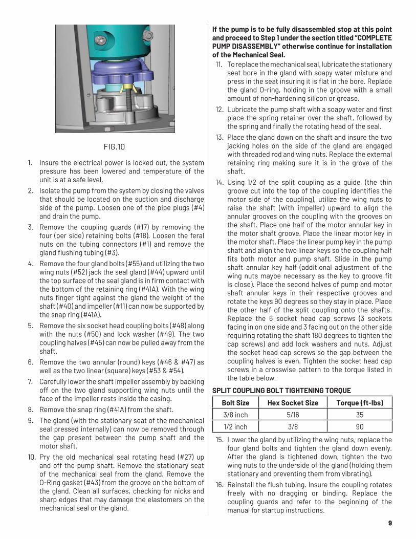
FIG.10
1. Insure the electrical power is locked out, the system pressure has been lowered and temperature of the unit is at a safe level.
2. Isolate the pump from the system by closing the valves that should be located on the suction and discharge side of the pump. Loosen one of the pipe plugs (#4) and drain the pump.
3. Remove the coupling guards (#17) by removing the four (per side) retaining bolts (#18). Loosen the feral nuts on the tubing connectors (#1) and remove the gland flushing tubing (#3).
4. Remove the four gland bolts (#55) and utilizing the two wing nuts (#52) jack the seal gland (#44) upward until the top surface of the seal gland is in firm contact with the bottom of the retaining ring (#41A). With the wing nuts finger tight against the gland the weight of the shaft (#40) and impeller (#11) can now be supported by the snap ring (#41A).
5. Remove the six socket head coupling bolts (#48) along with the nuts (#50) and lock washer (#49). The two coupling halves (#45) can now be pulled away from the shaft.
6. Remove the two annular (round) keys (#46 & #47) as well as the two linear (square) keys (#53 & #54).
7. Carefully lower the shaft impeller assembly by backing off on the two gland supporting wing nuts until the face of the impeller rests inside the casing.
8. Remove the snap ring (#41A) from the shaft. 9. The gland (with the stationary seat of the mechanical
seal pressed internally) can now be removed through the gap present between the pump shaft and the motor shaft.
10. Pry the old mechanical seal rotating head (#27) up and off the pump shaft. Remove the stationary seat of the mechanical seal from the gland. Remove the O-Ring gasket (#43) from the groove on the bottom of the gland. Clean all surfaces, checking for nicks and sharp edges that may damage the elastomers on the mechanical seal or the gland.
If the pump is to be fully disassembled stop at this point and proceed to Step 1 under the section titled “COMPLETE PUMP DISASSEMBLY” otherwise continue for installation of the Mechanical Seal.
11. To replace the mechanical seal, lubricate the stationary seat bore in the gland with soapy water mixture and press in the seat insuring it is flat in the bore. Replace the gland O-ring, holding in the groove with a small amount of non-hardening silicon or grease.
12. Lubricate the pump shaft with a soapy water and first place the spring retainer over the shaft, followed by the spring and finally the rotating head of the seal.
13. Place the gland down on the shaft and insure the two jacking holes on the side of the gland are engaged with threaded rod and wing nuts. Replace the external retaining ring making sure it is in the grove of the shaft.
14. Using 1/2 of the split coupling as a guide, (the thin groove cut into the top of the coupling identifies the motor side of the coupling), utilize the wing nuts to raise the shaft (with impeller) upward to align the annular grooves on the coupling with the grooves on the shaft. Place one half of the motor annular key in the motor shaft groove. Place the linear motor key in the motor shaft. Place the linear pump key in the pump shaft and align the two linear keys so the coupling half fits both motor and pump shaft. Slide in the pump shaft annular key half (additional adjustment of the wing nuts maybe necessary as the key to groove fit is close). Place the second halves of pump and motor shaft annular keys in their respective grooves and rotate the keys 90 degrees so they stay in place. Place the other half of the split coupling onto the shafts. Replace the 6 socket head cap screws (3 sockets facing in on one side and 3 facing out on the other side requiring rotating the shaft 180 degrees to tighten the cap screws) and add lock washers and nuts. Adjust the socket head cap screws so the gap between the coupling halves is even. Tighten the socket head cap screws in a crosswise pattern to the torque listed in the table below.
SPLIT COUPLING BOLT TIGHTENING TORQUE
Bolt Size Hex Socket Size Torque (ft-lbs)
3/8 inch 5/16 35
1/2 inch 3/8 90
15. Lower the gland by utilizing the wing nuts, replace the four gland bolts and tighten the gland down evenly. After the gland is tightened down, tighten the two wing nuts to the underside of the gland (holding them stationary and preventing them from vibrating).
16. Reinstall the flush tubing. Insure the coupling rotates freely with no dragging or binding. Replace the coupling guards and refer to the beginning of the manual for startup instructions.

10
• SEAL REPLACEMENT MODELS(Models 10x10x19, 10x10x14, 12x12x14, 12x12x18, 14x14x15 and 14x14x18 only)
FIG. 11
Refer the Tools mentioned in the required tools and fixtures for pump disassembly
REPLACING THE MECHANICAL SEAL1. Ensure the electrical power is locked out, the system
pressure has been lowered and temperature of the unit is at a safe level.
2. Isolate the pump from the system by closing the valves that should be located on the suction and discharge side of the pump. Loosen one of the pipe plugs (#4) and drain the pump.
FIG. 12
3. Remove the coupling guards (#17) by removing the four (per side) cap screws (#18). Loosen the ferrule nuts on the tubing connectors (#1) and remove the gland flushing tubing (#3).
FIG. 13
If 8b2 Mechanical seal has to be replaced stop at this point and proceed to step 28
FOR TYPE 21 MECHANICAL SEAL4. Size 10x10x14 - Loosen the four gland bolts (#55) so
that there is at least ½” gap between their head and the gland. Tighten the two set screws (#20) pre-installed in to the gland keeping all the loosened gland bolts engaged in case of 10x10x14 pump, they will keep the gland from rotating as it is lifted.
FIG. 14A
All Other Sizes - Loosen the four gland bolts (#55). Two should be loosened so that there is at least ½” gap between their head and the gland, and other two removed and transferred to the provided jacking holes. The other two bolts need to be kept engaged in case of 10x10x14 pump) with the gland to keep the gland from rotating as it is lifted.
FIG. 14B
5. Start tightening the bolts/set screws to jack the seal gland (#44) upward until the top surface of the seal gland makes a firm contact with the bottom of the retaining ring (#41A). Make sure to alternate tightening of the bolts so the gland is raised evenly.
6. With the bolts (#55) tightened against the gland, the weight of the shaft (#40) and impeller (#11) can now be supported by the gland and the split coupling (#45) can be removed without the shaft dropping.

11
7. Remove the four coupling set screws (#20) followed by six/four socket head coupling bolts (#48) along with the nuts (#50) and spring washers (#49). The two coupling halves (#45) can now be pulled away from the shaft.
FIG. 15
8. Remove the two linear (square) keys (#53, #54).
FIG. 16
9. Carefully lower the shaft impeller assembly by backing off on the two gland supporting bolts (the two set screws in case of 10x10x14) until the face of the impeller rests inside the casing.
10. Remove the retaining ring (#41A) from the shaft.11. Remove two remaining gland bolts (#55) which are
engaged with seal plate (#35A).12. The gland (#44) (with the stationary seat of the
mechanical seal pressed internally) can now be removed through the gap present between the pump shaft and the motor shaft.
FIG. 1713. Pry the old mechanical seal (#27) rotating head, spring
& spring retainer up and off the pump shaft. 14. Remove the stationary part of the mechanical seal
from the gland. Remove the O-Ring gasket (#43) from the groove on the bottom of the gland.
FIG. 18
If the pump is to be fully disassembled stop at this point and proceed to Step 1 under the section titled “COMPLETE PUMP DISASSEMBLY” otherwise continue for installation of the Mechanical Seal.
15. Clean all surfaces of the gland, checking for nicks and sharp edges that may damage the elastomers on the mechanical seal or the gland.
16. To replace the mechanical seal, lubricate the stationary seat bore in the gland with soapy water mixture and press in the seat ensuring it is flat in the bore.
17. Replace the gland O-ring, holding in the groove with a small amount of non-hardening silicon or grease.
18. Lubricate the pump shaft with soapy water. Place the spring retainer over the shaft, followed by the spring and finally the rotating head of the seal until it rests over lower retaining ring.
FIG. 19
19. Place the gland down on the seal plate and ensure the two jacking bolts/set screws are engaged.
20. Engage the remaining two gland bolts loosely with the gland and seal plate (all the four bolts in case of 10x10x14 pump) to restrict the motion of the gland about shaft axis.
21. Replace the external retaining ring making sure it is in the groove of the shaft.
22. Using half of the split coupling as a guide, (the tapping for setscrews identifies the motor side of the coupling) utilize the jacking bolts to raise the shaft (with impeller) upward until the step inside the coupling touches motor shaft end face so that pre specified distance between pump shaft & motor shaft is maintained.

12
FIG. 20
23. Place the linear motor key in the motor shaft. Place the linear pump key in the pump shaft and align the two linear keys so that the other coupling half fits over both motor and pump shaft.
24. Place the other half of the split coupling onto the shafts. Replace the six/four socket head cap screws (three/two sockets facing in on one side and three/two facing out on the other side requiring rotating the shaft 180 degrees to tighten the cap screws) and add spring washers and nuts. Adjust the socket head cap screws to maintain even gap between coupling halves. Tighten the socket head cap screws in a crosswise pattern. The minimum tightening torque to be maintained is 120 lbf-ft but should not exceed 130lbf-ft. Make sure that all the bolts are tightened to same torque.
FIG. 21
• Tighten to the required torque in three steps as follows:a) First time – Tighten to 50% of the specified torqueb) Second time – Tighten to 75% of the specified
torquec) Third time – Tighten to 100% of the specified
torque 25. Tighten grub screws to fix the axial location of coupling
(in a crossing pattern). The minimum tightening torque to be maintained is 30 lbf-ft but should not exceed 65lbf-ft. Make sure that all the bolts are tightened to same torque.
• Tighten to the required torque in three steps as followsa) First time – Tighten to 50% of the specified torqueb) Second time – Tighten to 75% of the specified
torque
c) Third time – Tighten to 100% of the specified torque
26. Lower the gland by disengaging the jacking bolts/set screws and tighten the gland to the seal plate using the four gland bolts.
27. Reinstall the flush tubing. Ensure that impeller and motor rotate freely with no dragging or binding. Replace the coupling guards and refer to the beginning of the manual for startup instructions.
FOR TYPE 8B2 MECHANICAL SEAL IN ALL MODELS 28. Loosen the four gland bolts (#55). Keeping the two
bolts engaged with the gland to restrict the motion of the gland about shaft axis, engage the other two bolts into the threaded holes in Jacking Plate (#10). Place the Jacking plate sub-assembly beneath the retaining ring, aligning the bolts with two clear blind holes in the gland (#44). Tighten the engaged bolts simultaneously such that the jacking plate makes a firm contact with the bottom of the retaining ring (41A).
FIG. 22
29. Remove set screws (#21) from rotating part of the seal and move the rotating part slightly upwards so that it does not hinder shaft (#40) axial movement when the jacking plate (#10) is backed off. Failure to do so could cause damage to the stationary seat when the impeller (#11) is lowered.
FIG. 23
30. With the Jacking bolts tight against the jacking plate, the weight of the shaft (#40) and impeller(#11) can now be supported by the gland (#44) and the split coupling (#45) can be removed without the shaft dropping.
31. Remove the four coupling set screws (#20) followed by six/four socket head coupling bolts (#48) along with the nuts (#50) and spring washer (#49). The two coupling halves (#45) can now be pulled away from the shaft.

13
32. Remove the two linear (square) keys (#53, #54).33. Carefully lower the shaft impeller assembly by backing
off the two gland plate supporting bolts until the face of the impeller rests inside the casing.
34. Remove the retaining ring (#41A) from the shaft.35. Pry the old mechanical seal (#27) rotating part off the
pump shaft.36. Remove the jacking plate (#10) and bolts sub-assembly.37. Inspect the surface of the stationary seat. If damaged,
remove gland bolts (#55), and remove gland (#44) through the gap present between the pump shaft and the motor shaft.
FIG. 24
38. Remove the stationary part along with the inboard and outboard stationary gasket off the pump shaft.
If the pump is to be fully disassembled proceed to Step 1 under the section titles “COMPLETE PUMP DISASSEMBLY”, otherwise continue for installation of the 8B2 Seal.
39. Clean all surfaces of the gland, checking for nicks and sharp edges that may damage the elastomers on the mechanical seal or the gland.
40. Remove the mechanical seal from its packaging, inspect for any damage, and keep seal faces clean and free from contaminants during installation. DO NOT GREASE OR LUBRICATE SEAL FACES
41. Use soap, petro gel, glycerin, etc. for lubrication for ease of assembly.
42. If removed, install the inboard stationary gasket and the stationary part of seal on to the shaft. Then place the outboard stationary gasket over the stationary part.
43. Next place the seal gland over the stationary part and gaskets, making sure that all the gaskets have been installed properly before securing the gland bolts.
44. Now install the rotating part of the seal over the shaft. Do not tighten seal set screws at this time.
FIG. 25
45. Replace the external retaining ring making sure it is in the groove of the shaft.
46. Engage the jacking plate and bolt sub-assembly so that it touches the lower face of the retaining ring.
47. Using half of the split coupling as a guide, (the tapping for setscrews identifies the motor side of the coupling), utilize the Jacking plate and bolts sub-assembly to raise the shaft (with impeller) upward until the step inside the coupling touches motor shaft end face so that pre specified distance between pump shaft & motor shaft is maintained.
FIG. 26
48. Place the linear motor key in the motor shaft. Place the linear pump key in the pump shaft and align the two linear keys so that the other coupling half fits over motor and pump shaft.
49. Place the other half of the split coupling onto the shafts. Replace the six/four socket head cap screws (three/two sockets facing in on one side and three/two facing out on the other side requiring rotating the shaft 180 degrees to tighten the cap screws) and add spring washers and nuts. Adjust the socket head cap screws to maintain even gap between the coupling halves.
FIG. 27

14
50. Tighten the socket head cap screws in a crosswise pattern. The minimum tightening torque to be maintained is 120lbf-ft but should not exceed 130lbf-ft. Make sure that all the bolts are tightened to same torque.
• Tighten to the required torque in three steps as follows:a) First time – Tighten to 50% of the specified torqueb) Second time – Tighten to 75% of the specified
torquec) Third time – Tighten to 100% of the specified
torque 51. Tighten set screws to fix the location of coupling (in a
crossing pattern). The minimum tightening torque to be maintained is 30 lbf-ft but should not exceed 65lbf-ft. Make sure that all the bolts are tightened to same torque.
• Tighten to the required torque in three steps as follows:a) First time – Tighten to 50% of the specified torqueb) Second time – Tighten to 75% of the specified
torquec) Third time – Tighten to 100% of the specified
torque 52. Fasten the set screws of rotating part of the seal.
After maintaining the compression recommended by the seal manufacturer, tighten the set screws to a torque as recommended by the seal manufacturer.
53. Lower the jacking plate by utilizing bolts wing nuts, replace the four gland bolts and tighten the gland to the seal plate.
54. Reinstall the flush tubing. Ensure that the coupling rotates freely with no dragging or binding. Replace the coupling guards and refer to the beginning of the manual for startup instructions.
COMPLETE PUMP DISASSEMBLY• PUMP DISASSEMBLY MODELS
(1.5x1.5x9B, 2.5x2.5x7, 2.5x2.5x9, 2x2x12, 2x2x7, 2x2x9A/B/C, 3x3x12, 3x3x7A/B, 3x3x9A/B, 3x4x9, 4x4x11, 4x4x12, 4x4x7A/B, 4x4x9A/B, 4x5x9, 5x5x11, 5x5x12, 5x5x9, 6x6x11, 6x6x12, 6x6x9, 8x8x11, 8x8x12, 8x8x13.5, 10x10x13.5)
1. With the coupling, gland and mechanical seal removed, remove the bolts (#32) and nuts (#31) holding the motor to the bracket (#35). Pull the motor up and away utilizing suitable lifting equipment.
2. Remove the snap ring (#41B) from the shaft (#40). 3. Remove the cap screws (#5) holding the bracket (#35)
to the casing (#6). Utilizing suitable lifting equipment lift the bracket straight up and off the casing and over the shaft. Take care when lifting to insure a straight lift, the carbon bushing (#42) may be damaged by uneven lifting.
4. Remove the casing gasket (#8) from the casing and bracket.
5. Lift the rotating assembly from the casing.
6. Unscrew impeller screw (#9) and remove impeller seal (#9C).
7. Slide impeller (#11) and impeller key (#12) from shaft.8. Now remove the impeller washer (#9A).

15
9. Remove wear rings (#7, #16) from the casing and bracket.
10. Press out the carbon bushing (#42) from the bore inside the bracket (at the base of the packing box). During reassembly the new bushing must be pressed in evenly or it can crack.
11. Pump reassembly is performed in the reverse order. • PUMP DISASSEMBLY MODELS
(Models 10x10x19, 10x10x14, 12x12x14, 12x12x18, 14x14x15 and 14x14x18 only)
1. With the coupling (#45), gland (#44) and mechanical seal (#27) removed, remove the bolts (#32), nuts (#31) and washers (#32A) holding the motor to the bracket.
2. Pull the motor up and away utilizing suitable lifting equipment.
3. Remove the lower snap ring (#41B) from the pump shaft.
4. Remove the cap screws (#5) and washers (#5A) holding the bracket (#35) to the seal plate (#35A). Utilizing suitable lifting equipment lift the bracket straight up.
5. Remove the cap screws (#5) holding the seal plate to the casing (#6) and by utilizing two bolts jack the seal plate upwards. Utilizing suitable lifting equipment lift the seal plate straight up. Take care when lifting to ensure a straight lift.
FIG. 28
FIG. 29
6. Remove carbon bushing (#42) from the bore inside the seal plate. During reassembly the new bushing must be pressed in evenly or it can crack.
7. Remove O-rings/gaskets (#8 and #8A) from the seal plate
FIG. 308. Unscrew impeller screw (#9), remove impeller washer
(#9A) and impeller seal (#9C).9. Slide impeller (#11) and impeller key (#12) from shaft.10. Remove spire bush (#13) from the impeller bore using
a small puller. During reassembly the new bushing must be pressed evenly or it can crack.
11. Remove wear rings (#7) & (#16) from the casing and seal plate with the help of puller.
FIG. 31
12. Remove sleeve (#25A) from casing spire with the help of a puller.
13. Remove nameplate (#34) and screws (#33) only if
replacement is needed.
INSPECTIONOnce the pumping unit is disassembled, component parts should be inspected to determine their condition. Worn parts should be reconditioned to like-new condition or replaced.
ASSEMBLYPump reassembly is performed in the reverse order. During the assembly procedure, take care not to damage any of the component parts and avoid contamination (dirt, debris, moisture, etc.) to the unit.

16
MODEL 382A SCP-Base-Motor
(1.5x1.5x9B, 2.5x2.5x7, 2.5x2.5x9, 2x2x12, 2x2x7, 2x2x9A/B/C, 3x3x12, 3x3x7A/B, 3x3x9A/B, 3x4x9, 4x4x11, 4x4x12, 4x4x7A/B, 4x4x9A/B, 4x5x9, 5x5x11, 5x5x12, 5x5x9, 6x6x11, 6x6x12, 6x6x9, 8x8x11, 8x8x12, 8x8x15, 10x10x15)
FIG. 32

17
MODEL 382B SC VERTICAL IN-LINE PUMPTC-Motor
(Model 10x10x19)
FIG.33

18
MODEL 382B SC VERTICAL IN-LINE PUMP
TC-Motor
(Models 10x10x14, 12x12x14, 12x12x18, 14x14x15 and 14x14x18)
FIG. 34

19
MODEL 382B SC VERTICAL IN-LINE PUMP
TC-Motor
(Models 8x8x13.5 & 10x10x13.5)
FIG.35

20
PART LIST FOR 382 SC VERTICAL INLINE PUMPSReference: FIG. 32, 33, 34, 35 (Exploded Views)
ITEM NO. DESCRIPTION1 COMP. ELBOW2 COMP. CONNECTOR3 TUBING4 PIPE PLUG
4A PIPE PLUG5 CAP SCREW
5A WASHER6 CASING7 WEAR RING8 GASKET9 IMPELLER SCREW
9A WASHER9C CAP SCREW SEAL10 JACKING PLATE11 IMPELLER12 IMPELLER KEY13 IMPELLER BUSH16 WEAR RING17 COUPLING GUARD18 GUARD MOUNTING SCREW20 SET SCREW
23A WEAR RING23B WEAR RING25A SPIRE SLEEVE27 SEAL31 HEX NUT (MOTOR SIDE)32 CAP SCREW
32A LOCK WASHER (MOTOR SIDE)33 SCREW34 NAME PLATE35 BRACKET
35A SEAL PLATE39 CAP SCREW40 SHAFT
41 (A, B) RETAINING RING42 THROTTLE BUSHING43 GLAND O-RING44 GLAND45 SPLIT COUPLING48 CAP SCREW49 LOCK WASHER50 HEX NUT51 STUD52 WING NUT53 PUMP COUPLING KEY54 MOTOR COUPLING KEY55 GLAND CAP SCREW
55A GLAND WASHER73 SPOOL BASE

AURORA
800 Airport Road North Aurora, Illinois 60542630-859-7000 www.aurorapump.com
WARRANTYSeller warrants equipment (and its component parts) of its own manufacture against defects in materials and workmanship under normal use and service for one (1) year from the date of installation or start-up, or for eighteen (18) months after the date of shipment, whichever occurs first. Seller does not warrant accessories or components that are not manufactured by Seller; however, to the extent possible, Seller agrees to assign to Buyer its rights under the original manufacturer's warranty, without recourse to Seller. Buyer must give Seller notice in writing of any alleged defect covered by this warranty (together with all identifying details, including the serial number, the type of equipment, and the date of purchase) within thirty (30) days of the discovery of such defect during the warranty period. No claim made more than 30 days after the expiration of the warranty period shall be valid. Guarantees of performance and warranties are based on the use of original equipment manufactured (OEM) replacement parts. Seller assumes no responsibility or liability if alterations, non-authorized design modifications and/or non-OEM replacement parts are incorporated If requested by Seller, any equipment (or its component parts) must be promptly returned to Seller prior to any attempted repair, or sent to an authorized service station designated by Seller, and Buyer shall prepay all shipping expenses. Seller shall not be liable for any loss or damage to goods in transit, nor will any warranty claim be valid unless the returned goods are received intact and undamaged as a result of shipment. Repaired or replaced material returned to customer will be shipped F.O.B., Seller's factory. Seller will not give Buyer credit for parts or equipment returned to Seller, and will not accept delivery of any such parts or equipment, unless Buyer has obtained Seller's approval in writing. The warranty extends to repaired or replaced parts of Seller's manufacture for ninety (90) days or for the remainder of the original warranty period applicable to the equipment or parts being repaired or replaced, whichever is greater. This warranty applies to the repaired or replaced part and is not extended to the product or any other component of the product being repaired. Repair parts of its own manufacture sold after the original warranty period are warranted for a period of one (1) year from shipment against defects in materials and workmanship under normal use and service. This warranty applies to the replacement part only and is not extended to the product or any other component of the product being repaired. Seller may substitute new equipment or improve part(s) of any equipment judged defective without further liability. All repairs or services performed by Seller, which are not covered by this warranty, will be charged in accordance with Seller's standard prices then in effect.
THIS WARRANTY IS THE SOLE WARRANTY OF SELLER AND SELLER HEREBY EXPRESSLY DISCLAIMS AND BUYER WAIVES ALL OTHER WARRANTIES EXPRESSED, IMPLIED IN LAW OR IMPLIED IN FACT, INCLUDING ANY WARRANTIES OF MERCHANTABILITY OR FITNESS FOR A PARTICULAR PURPOSE. Seller's sole obligation under this warranty shall be, at its option, to repair or replace any equipment (or its component parts) which has a defect covered by this warranty, or to refund the purchase price of such equipment or part. Under the terms of this warranty, Seller shall not be liable for (a) consequential, collateral, special or liquidated losses or damages; (b) equipment conditions caused by normal wear and tear, abnormal conditions of use, accident, neglect, or misuse of said equipment; (c) the expense of, and loss or damage caused by, repairs or alterations made by anyone other than the Seller; (d) damage caused by abrasive materials, chemicals, scale deposits, corrosion, lightning, improper voltage, mishandling, or other similar conditions; (e) any loss, damage, or expense relating to or resulting from installation, removal or reinstallation of equipment; (f) any labor costs or charges incurred in repairing or replacing defective equipment or parts, including the cost of reinstalling parts that are repaired or replaced by Seller; (g) any expense of shipment of equipment or repaired or replacement parts; or (h) any other loss, damage or expense of any nature.
The above warranty shall not apply to any equipment which may be separately covered by any alternate or special warranties.
PERFORMANCE: In the absence of Certified Pump Performance Tests, equipment performance is not warranted or guaranteed. Performance curves and other information submitted to Buyer are approximate and no warranty or guarantee shall be deemed to arise as a result of such submittal. All testing shall be done in accordance with Seller's standard policy under Hydraulic Institute procedures.
LIABILITY LIMITATIONS: Under no circumstances shall the Seller have any liability under the Order or otherwise for liquidated damages or for collateral, consequential or special damages or for loss of profits, or for actual losses or for loss of production or progress of construction, regardless of the cause of such damages or losses. In any event, Seller's aggregate total liability under the Order or otherwise shall not exceed the contract price.
ACTS OF GOD: Seller shall in no event be liable for delays in delivery of the equipment or other failures to perform caused by fires, acts of God, strikes, labor difficulties, acts of governmental or military authorities, delays in transportation or procuring materials, or causes of any kind beyond Seller's control.
COMPLIANCE WITH LAW: Seller agrees to comply with all United States laws and regulations applicable to the manufacturing of the subject equipment. Such compliance shall include: The Fair Labor Standards Acts of 1938, as amended; Equal Employment Opportunity clauses of Executive Order 11246, as amended; Occupational Safety and Health Act of 1970 and the standards promulgated thereunder, if applicable. Since compliance with the various Federal, State, and Local laws and regulations concerning occupational health and safety, pollution or local codes are affected by the use, installation and operation of the equipment and other matters over which Seller has no control, Seller assumes no responsibility for compliance with those laws and regulations, whether by way of indemnity, warranty, or otherwise. It is incumbent upon the Buyer to specify equipment which complies with local codes and ordinances.

22
This page intentionally left blank

23
This page intentionally left blank

24


![NORTA MIT PRESENTATION.pptx [Read-Only] · • Centrifugal pumps • Side channel pumps • Gear pumps • Screw pumps • Single screw pumps • Piston pumps • Vacuum pumps •](https://static.fdocuments.us/doc/165x107/5ec27ab9e3ef591d10504c3a/norta-mit-read-only-a-centrifugal-pumps-a-side-channel-pumps-a-gear-pumps.jpg)


