
Split and Segmented-Type Helical Coils for the Heliotron ...
5
Plasma and Fusion Research: Regular Articles Volume 5, S1026 (2010) Split and Segmented-Type Helical Coils for the Heliotron Fusion Energy Reactor Nagato YANAGI, Kiyohiko NISHIMURA, Gourab BANSAL 1) , Akio SAGARA and Osamu MOTOJIMA National Institute for Fusion Science, 322-6 Oroshi-cho, Toki, Gifu 509-5292, Japan 1) Institute for Plasma Research, Bhat, Gandhinagar, Gujarat, 382-428 India (Received 9 January 2009 / Accepted 8 July 2009) Configuration optimization is carried out for the heliotron-type fusion energy reactor FFHR. One of the important issues is to find sufficient clearances between the ergodic region outside the nested magnetic surfaces and blankets at the inboard side of the torus so that direct losses of alpha particles are minimized and the heat flux on the first walls is reduced. The latest design has a fairly large major radius R c ∼ 17 m of the helical coils in order to satisfy this condition. It has been found, as an alternative design, that equivalent clearances are obtained with R c = 15 m by employing a lower helical pitch parameter and splitting the helical coils in the poloidal cross-section at the outboard side. Furthermore, splitting the helical coils provides another modified configuration at R c ∼ 17 m that ensures magnetic well formation in the fairly large nested magnetic surfaces with outward shifted configurations. From the engineering viewpoint, we propose that such helical coils be constructed by prefabricating half-pitch segments using high-temperature superconductors; the segments are then to be assembled on site with joints. c 2010 The Japan Society of Plasma Science and Nuclear Fusion Research Keywords: heliotron, FFHR, configuration optimization, split-type helical coils, high-temperature superconduc- tor, segmented-type fabrication of helical coils DOI: 10.1585/pfr.5.S1026 1. Introduction Based on the steadfast progress of fusion relevant plasma experiments in the Large Helical Device (LHD) [1], the conceptual design studies on the heliotron-type fusion energy reactor FFHR are being conducted on both physics and engineering issues [2, 3]. For FFHR, a mag- netic configuration similar to that of LHD is employed so that the confined plasma is net current-free with steady- state operations. Though configuration optimization is still being pursued, the present choice gives a major radius of 14-18 m with a toroidal magnetic field of 6-4 T in order to generate ∼3 GW of fusion power. The stored magnetic en- ergy of the superconducting coil system should be in the range of 120-150 GJ. In these studies, the helical pitch parameter γ defined by (m/l)(a c /R c ) for continuous helical coils (having the toroidal pitch number m, poloidal pole number l, average minor radius a c and major radius R c ) has been chosen to be lower than 1.25, the parameter adopted for the present LHD. This choice is made for the purpose of ensuring a sufficient blanket space (thickness > 1 m) between the er- godic region of magnetic field lines (outside the nested magnetic surfaces) and the blankets [4]. At the same time, the lower γ reduces the electromagnetic hoop-forces on the helical coils. The configuration proposed in 2005, “FFHR- 2m1,” has m = 10, l = 2, R c = 14 m and a c = 3.22 m with author’s e-mail: [email protected] γ = 1.15. One of the difficult issues with this configuration is the still observed interferences between the ergodic region and blankets especially at the inboard side of the torus. In order to reduce the heat flux on the blankets, a “helical x-point diverter (HXD)” was proposed [5]. However, this choice gives an extremely high heat flux on the limiter-like struc- tures. Moreover, the confinement of alpha particles dete- riorates by cutting the magnetic field lines in the ergodic region where alpha particles are still confined [6]. In this respect, two approaches are being considered to secure more sufficient clearances. One is to enlarge the ma- jor radius of the helical coils, and the currently improved design, “FFHR-2m2,” gives R c = 17.33 m and a c = 4.02 m with γ = 1.20, which assures a blanket space of 0.95 m at the inboard side. The other approach is to find optimized magnetic configurations by modifying the winding laws of the helical coils. In this respect, we found that favorable configurations could be obtained by splitting the helical coils in the poloidal cross-section [7]. The new configu- rations are named “FFHR-2S,” and two options “Type-I” and “Type-II” are discussed in this paper. From the engineering viewpoint, we also propose that such complicated helical coils with a continuous manner and huge size be constructed by prefabricating half-pitch segments using high-temperature superconductors (HTS); the segments are then to be assembled on site with joints. c 2010 The Japan Society of Plasma Science and Nuclear Fusion Research S1026-1
Transcript of Split and Segmented-Type Helical Coils for the Heliotron ...

Plasma and Fusion Research: Regular Articles Volume 5, S1026 (2010)
Split and Segmented-Type Helical Coils for the Heliotron FusionEnergy Reactor
Nagato YANAGI, Kiyohiko NISHIMURA, Gourab BANSAL1), Akio SAGARAand Osamu MOTOJIMA
National Institute for Fusion Science, 322-6 Oroshi-cho, Toki, Gifu 509-5292, Japan1)Institute for Plasma Research, Bhat, Gandhinagar, Gujarat, 382-428 India
(Received 9 January 2009 / Accepted 8 July 2009)
Configuration optimization is carried out for the heliotron-type fusion energy reactor FFHR. One of theimportant issues is to find sufficient clearances between the ergodic region outside the nested magnetic surfacesand blankets at the inboard side of the torus so that direct losses of alpha particles are minimized and the heatflux on the first walls is reduced. The latest design has a fairly large major radius Rc ∼ 17 m of the helicalcoils in order to satisfy this condition. It has been found, as an alternative design, that equivalent clearancesare obtained with Rc = 15 m by employing a lower helical pitch parameter and splitting the helical coils in thepoloidal cross-section at the outboard side. Furthermore, splitting the helical coils provides another modifiedconfiguration at Rc ∼ 17 m that ensures magnetic well formation in the fairly large nested magnetic surfaceswith outward shifted configurations. From the engineering viewpoint, we propose that such helical coils beconstructed by prefabricating half-pitch segments using high-temperature superconductors; the segments are thento be assembled on site with joints.c© 2010 The Japan Society of Plasma Science and Nuclear Fusion Research
Keywords: heliotron, FFHR, configuration optimization, split-type helical coils, high-temperature superconduc-tor, segmented-type fabrication of helical coils
DOI: 10.1585/pfr.5.S1026
1. IntroductionBased on the steadfast progress of fusion relevant
plasma experiments in the Large Helical Device (LHD)[1], the conceptual design studies on the heliotron-typefusion energy reactor FFHR are being conducted on bothphysics and engineering issues [2, 3]. For FFHR, a mag-netic configuration similar to that of LHD is employed sothat the confined plasma is net current-free with steady-state operations. Though configuration optimization is stillbeing pursued, the present choice gives a major radius of14-18 m with a toroidal magnetic field of 6-4 T in order togenerate ∼3 GW of fusion power. The stored magnetic en-ergy of the superconducting coil system should be in therange of 120-150 GJ.
In these studies, the helical pitch parameter γ definedby (m/l)(ac/Rc) for continuous helical coils (having thetoroidal pitch number m, poloidal pole number l, averageminor radius ac and major radius Rc) has been chosen tobe lower than 1.25, the parameter adopted for the presentLHD. This choice is made for the purpose of ensuring asufficient blanket space (thickness > 1 m) between the er-godic region of magnetic field lines (outside the nestedmagnetic surfaces) and the blankets [4]. At the same time,the lower γ reduces the electromagnetic hoop-forces on thehelical coils. The configuration proposed in 2005, “FFHR-2m1,” has m = 10, l = 2, Rc = 14 m and ac = 3.22 m with
author’s e-mail: [email protected]
γ = 1.15.One of the difficult issues with this configuration is the
still observed interferences between the ergodic region andblankets especially at the inboard side of the torus. In orderto reduce the heat flux on the blankets, a “helical x-pointdiverter (HXD)” was proposed [5]. However, this choicegives an extremely high heat flux on the limiter-like struc-tures. Moreover, the confinement of alpha particles dete-riorates by cutting the magnetic field lines in the ergodicregion where alpha particles are still confined [6].
In this respect, two approaches are being considered tosecure more sufficient clearances. One is to enlarge the ma-jor radius of the helical coils, and the currently improveddesign, “FFHR-2m2,” gives Rc = 17.33 m and ac = 4.02 mwith γ = 1.20, which assures a blanket space of 0.95 m atthe inboard side. The other approach is to find optimizedmagnetic configurations by modifying the winding laws ofthe helical coils. In this respect, we found that favorableconfigurations could be obtained by splitting the helicalcoils in the poloidal cross-section [7]. The new configu-rations are named “FFHR-2S,” and two options “Type-I”and “Type-II” are discussed in this paper.
From the engineering viewpoint, we also propose thatsuch complicated helical coils with a continuous mannerand huge size be constructed by prefabricating half-pitchsegments using high-temperature superconductors (HTS);the segments are then to be assembled on site with joints.
c© 2010 The Japan Society of PlasmaScience and Nuclear Fusion Research
S1026-1

Plasma and Fusion Research: Regular Articles Volume 5, S1026 (2010)
Fig. 1 Vacuum magnetic surfaces at (a) the toroidal angle φ = 0◦ and (b) φ = 18◦ of FFHR-2m2 (Type-A) with Rc = 17.33 m, ac = 4.02 mand γ = 1.2. The magnetic axis is shifted inward at Rp = 16.0 m. (c) Plan view of the coils.
Fig. 2 Vacuum magnetic surfaces at (a) the toroidal angle φ = 0◦ and (b) φ = 18◦ of FFHR-2S Type-I with Rc = 15.0 m, ac = 3.0 m andγ = 1.0. The magnetic axis is at the center of the helical coils (Rp = 15.0 m). (c) Plan view of the coils.
Fig. 3 Vacuum magnetic surfaces at (a) the toroidal angle φ = 0◦ and (b) φ = 18◦ of FFHR-2S Type II with Rc = 17.33 m, ac = 4.02 mand γ = 1.2. The magnetic axis is shifted outward at Rp = 18.0 m. (c) Plan view of the coils.
S1026-2

Plasma and Fusion Research: Regular Articles Volume 5, S1026 (2010)
The feasibility of the HTS option is briefly discussed inthis paper.
2. Proposal of Split-Type Helical CoilsThe vacuum magnetic surfaces of the FFHR-2m2 con-
figuration are shown in Fig. 1, and it is seen that the mag-netic axis is shifted inward (located at Rp = 16.0 m) inorder to have good particle confinement. It is noted thatthe magnetic surfaces have good symmetry with the in-ward shifted configuration. On the other hand, it was previ-ously found that the symmetry of magnetic surfaces wouldbe significantly improved, without shifting the magneticaxis inward, by increasing the current density of the heli-cal coils at the inboard side of the torus while decreasingat the outboard side [8–10]. This situation can be practi-cally realized by splitting the helical coils in the poloidalcross-section at the outboard side.
Here, we newly found that drastically large nestedmagnetic surfaces (or the plasma volume) can be ob-tained by the symmetry improvement using split-type he-lical coils even if the original configuration (non-split heli-cal coils) possesses a fairly large ergodic region outside therelatively small nested magnetic surfaces. In this respect,we first found that sufficient clearances are obtained evenwith a smaller major radius of Rc = 15.0 m (than that of thestandard configuration of FFHR-2m2 with Rc = 17.33 m)by splitting the helical coils and at the same time by reduc-ing the helical pitch parameter to be as low as γ = 1.0 [7].The vacuum magnetic surfaces of this configuration areshown in Fig. 2. The magnetic axis is located at the centerof the helical coils and the blanket space of ∼1 m is securedat the inboard side. Here we should note that such a low he-lical pitch parameter has never been examined so far, as itis well known that one is almost in the so-called forbidden-zone for generating magnetic surfaces with a l = 2 he-liotron configuration [11]. We understand that the low he-lical pitch parameter is effective for compacting the sep-aratrix while the splitting of helical coils at the outboardside ensures larger nested magnetic surfaces as a result ofthe symmetry improvement. This configuration is named“FFHR-2S Type-I.” Owing to the smaller major radius, ourdesigns indicate the toroidal magnetic field to be as high as6 T, while it is 4.84 T for FFHR-2m2.
We then found that split-type helical coils could pro-vide another configuration based on the same conceptof symmetry improvement. The FFHR-2m2 has the in-ward shifted magnetic surfaces, which ensures good par-ticle confinement properties. On the other hand, it hasbeen recently found in the LHD plasma experiments thathigh electron density is achieved with a “superdense core(SDC)” at outward shifted configurations [12]. How-ever, one of the problems with this configuration is thatthe nested magnetic surfaces become considerably smallerthan those at inward shifted cases. Here, we proposethat fairly large nested magnetic surfaces be obtained even
Fig. 4 Radial profiles of (a) rotational transform and (b) mag-netic well depth for FFHR-2m2, FFHR-2S Type-I andType-II.
with outward shifted configurations by splitting the helicalcoils. Figure 3 shows an example of the vacuum magneticsurfaces using this concept, which is named “FFHR-2SType-II.” The basic parameters of this configuration are thesame as those for FFHR-2m2 except for the split-type he-lical coils, and the magnetic axis is located at Rp = 18.0 mwhere the toroidal magnetic field is 4.3 T. Though the orig-inal configuration gives∼35% reduction of the average mi-nor radius at Rp = 18.0 m compared to that at Rp = 16.0 m,it is only ∼7% with FFHR-2S Type-II. Here, it should benoted that a similar idea had been previously proposed[10].
Figure 4 shows the radial profiles of rotational trans-form and magnetic well depth for three configurations:FFHR-2m2, FFHR-2S Type-I and Type-II. As shown inFig. 4, magnetic well is observed within the entire mag-netic surfaces of FFHR-2S Type-II. On the other hand, therotational transform as well as shear are lower with thisconfiguration than those of the other two. For all these con-figurations, magnetic field properties concerning the neo-classical ripple transport and drift orbits of alpha particleswill be clarified in our future studies and further optimiza-tion will be pursued. Moreover, plasma beta should alsobe included in these studies and MHD stabilities will be
S1026-3
Plasma and Fusion Research: Regular Articles Volume 5, S1026 (2010)
investigated.We here note that split-type helical coils are useful not
only for configuration optimization but also for engineer-ing purposes, such as for injecting pellets and/or RF wavesfrom the high-field side through the gaps of helical coilsat the outboard side. It is proposed that ICRF heating hasgood accessibility in case of FFHR-2S configurations [13].
3. Proposal of Segmented-Type Fabri-cation of Helical CoilsFrom the engineering viewpoint, we admit that the
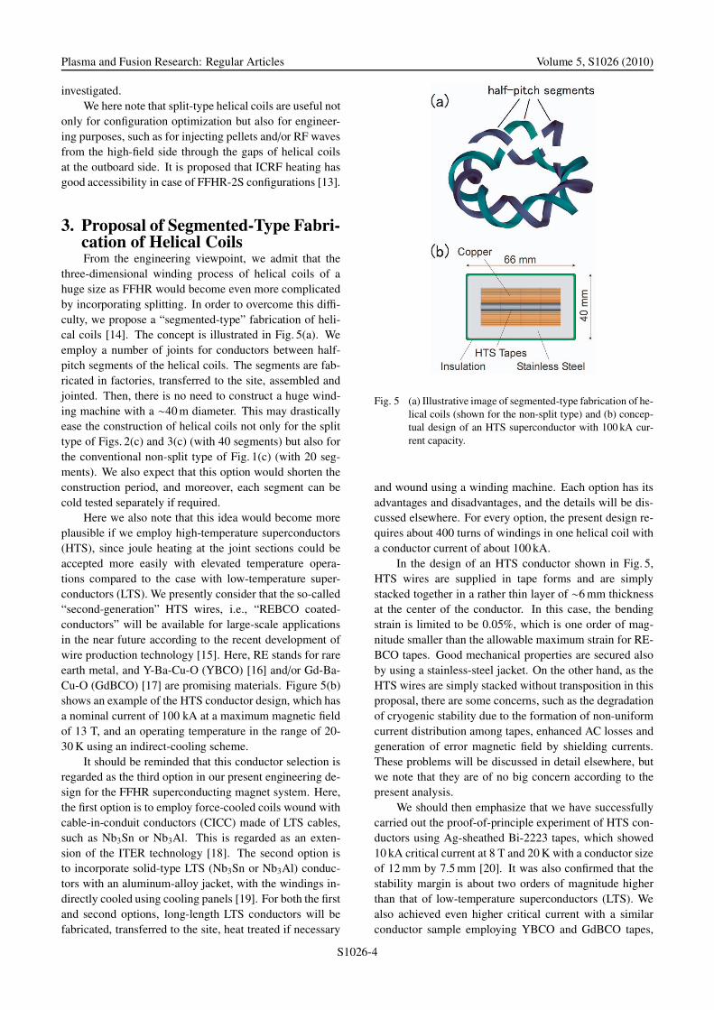
three-dimensional winding process of helical coils of ahuge size as FFHR would become even more complicatedby incorporating splitting. In order to overcome this diffi-culty, we propose a “segmented-type” fabrication of heli-cal coils [14]. The concept is illustrated in Fig. 5(a). Weemploy a number of joints for conductors between half-pitch segments of the helical coils. The segments are fab-ricated in factories, transferred to the site, assembled andjointed. Then, there is no need to construct a huge wind-ing machine with a ∼40 m diameter. This may drasticallyease the construction of helical coils not only for the splittype of Figs. 2(c) and 3(c) (with 40 segments) but also forthe conventional non-split type of Fig. 1(c) (with 20 seg-ments). We also expect that this option would shorten theconstruction period, and moreover, each segment can becold tested separately if required.
Here we also note that this idea would become moreplausible if we employ high-temperature superconductors(HTS), since joule heating at the joint sections could beaccepted more easily with elevated temperature opera-tions compared to the case with low-temperature super-conductors (LTS). We presently consider that the so-called“second-generation” HTS wires, i.e., “REBCO coated-conductors” will be available for large-scale applicationsin the near future according to the recent development ofwire production technology [15]. Here, RE stands for rareearth metal, and Y-Ba-Cu-O (YBCO) [16] and/or Gd-Ba-Cu-O (GdBCO) [17] are promising materials. Figure 5(b)shows an example of the HTS conductor design, which hasa nominal current of 100 kA at a maximum magnetic fieldof 13 T, and an operating temperature in the range of 20-30 K using an indirect-cooling scheme.
It should be reminded that this conductor selection isregarded as the third option in our present engineering de-sign for the FFHR superconducting magnet system. Here,the first option is to employ force-cooled coils wound withcable-in-conduit conductors (CICC) made of LTS cables,such as Nb3Sn or Nb3Al. This is regarded as an exten-sion of the ITER technology [18]. The second option isto incorporate solid-type LTS (Nb3Sn or Nb3Al) conduc-tors with an aluminum-alloy jacket, with the windings in-directly cooled using cooling panels [19]. For both the firstand second options, long-length LTS conductors will befabricated, transferred to the site, heat treated if necessary
Fig. 5 (a) Illustrative image of segmented-type fabrication of he-lical coils (shown for the non-split type) and (b) concep-tual design of an HTS superconductor with 100 kA cur-rent capacity.
and wound using a winding machine. Each option has itsadvantages and disadvantages, and the details will be dis-cussed elsewhere. For every option, the present design re-quires about 400 turns of windings in one helical coil witha conductor current of about 100 kA.
In the design of an HTS conductor shown in Fig. 5,HTS wires are supplied in tape forms and are simplystacked together in a rather thin layer of ∼6 mm thicknessat the center of the conductor. In this case, the bendingstrain is limited to be 0.05%, which is one order of mag-nitude smaller than the allowable maximum strain for RE-BCO tapes. Good mechanical properties are secured alsoby using a stainless-steel jacket. On the other hand, as theHTS wires are simply stacked without transposition in thisproposal, there are some concerns, such as the degradationof cryogenic stability due to the formation of non-uniformcurrent distribution among tapes, enhanced AC losses andgeneration of error magnetic field by shielding currents.These problems will be discussed in detail elsewhere, butwe note that they are of no big concern according to thepresent analysis.
We should then emphasize that we have successfullycarried out the proof-of-principle experiment of HTS con-ductors using Ag-sheathed Bi-2223 tapes, which showed10 kA critical current at 8 T and 20 K with a conductor sizeof 12 mm by 7.5 mm [20]. It was also confirmed that thestability margin is about two orders of magnitude higherthan that of low-temperature superconductors (LTS). Wealso achieved even higher critical current with a similarconductor sample employing YBCO and GdBCO tapes,
S1026-4

Plasma and Fusion Research: Regular Articles Volume 5, S1026 (2010)
and the details of this experiment will be reported else-where.
At the joint locations between half-pitch segments, theHTS conductors are cut in step-like structures, then over-lapped and jointed with superconducting sides facing eachother so that low-resistance joint can be formed [14]. Sincethe HTS conductor has a large temperature margin, thetemperature rise at a joint is not a big concern in terms ofcryogenic stability. Then, for a temperature rise of 5 K, thepower density of 990 W/m3 can be allowed, which meansthat a joint resistance of even 3 nΩ is acceptable [14]. Inthis case, ∼15 MW of additional refrigeration power is re-quired for the entire system with ∼8000 joints of conduc-tors (∼400 turns and 10 segments with 2 helical coils).However, this could be supplied by the surplus refrigera-tion power with elevated temperature operations comparedto the case of LTS coils operated at 4 K [20]. On theother hand, the joint resistance measured with single tapes(∼6 nΩ for 50 mm joint length) gives the expected over-all joint resistance of a 100 kA conductor to be as low as6 pΩ with 100 tapes and 500 mm joint length. This re-quires only ∼30 kW of additional refrigeration power forthe entire cooling system.
Helical coils assembled in segments may have a fur-ther possibility that they can be demountable for mainte-nance, as was originally proposed with NbTi superconduc-tors [21], and more recently with HTS conductors [22].
4. SummaryConfiguration optimization is being carried out as an
alternative design for the heliotron-type fusion energy re-actor FFHR by splitting the helical coils in the poloidalcross-section at the outboard side of the torus, which iseffective at having good symmetry of magnetic surfaces.Together by choosing a low helical pitch parameter ofγ = 1.0, the “FFHR-2S Type-I” configuration providesa smaller major radius of Rc = 15 m to secure sufficientblanket space of ∼1 m which is equivalent with that ob-tained for the presently standard design of “FFHR-2m2”with Rc = 17.33 m. On the other hand, by splitting the he-lical coils with the FFHR-2m2 size, the “FFHR-2S Type-II” configuration provides magnetic well formation in theentire region of the fairly large nested magnetic surfaceswith outward shifted configurations. From the engineeringviewpoint, it is proposed that continuous helical coils withsuch a complicated structure be assembled by prefabricat-
ing half-pitch segments. This method should drasticallyease the winding process and shorten the required period.For this purpose, it is feasible to employ high-temperaturesuperconductors (HTS), such as YBCO or GdBCO. Thejoule heating generated at ∼8000 joints is acceptable bythe elevated temperature operations and by the expectedlow joint resistances between HTS tapes.
AcknowledgmentsThe authors are grateful to T. Watanabe, S. Imagawa,
Y. Kozaki, T. Goto and other members in the FFHR de-sign group for valuable discussion and support. One of theauthors (N.Y.) thanks S. Morimoto for continuous encour-agement.
[1] O. Motojima et al., Nucl. Fusion 47, S668 (2007).[2] A. Sagara et al., Fusion Eng. Des. 81, 2703 (2006).[3] A. Sagara et al., Fusion Eng. Des. 83, 1690 (2008).[4] S. Imagawa et al., J. Plasma Fusion Res. SERIES 5, 537
(2002).[5] T. Morisaki et al., Fusion Eng. Des. 81, 2749 (2006).[6] T. Watanabe et al., Nucl. Fusion 46, 291 (2006).[7] N. Yanagi et al., in Proceedings of 17th International Toki
Conference (2007).[8] K. Nishimura and M. Fujiwara, Research Report of the
Institute of Plasma Physics, Nagoya University, IPPJ-869(1988).
[9] K. Nishimura and M. Fujiwara, J. Phys. Soc. Jpn. 64, 1164(1995).
[10] H. Akao, T. Watanabe and K. Nishikawa, JSPS Report63050027 (1988) 345 (in Japanese).
[11] K. Uo, Nucl. Fusion 13, 661 (1973).[12] H. Yamada et al., Plasma Phys. Control. Fusion 49, B487
(2007).[13] K. Saito et al., Proceedings of 18th International Toki Con-
ference (2008).[14] G. Bansal et al., Plasma Fusion Res. 3, S1049 (2008).[15] Y. Yamada et al., IEEE Trans. Appl. Supercond. 15, 2600
(2005).[16] A. Ibi et al., Physica C 445-448, 525 (2006).[17] H. Fukushima et al., Physica C 463-465, 501 (2007).[18] S. Imagawa, A. Sagara and Y. Kozaki, Plasma Fusion Res.
3, S1050 (2008).[19] K. Takahata et al., Fusion Eng. Des. 82, 1487 (2007).[20] G. Bansal et al., IEEE Trans. Appl. Supercond. 18, 1151
(2008).[21] K. Uo et al., Proc. 14th Symp. Fusion Techonol. 2, 1727
(1986).[22] H. Hashizume et al., Fusion Eng. Des. 63, 449 (2002).
S1026-5