Spiral Wound Gaskets e-Brochure - AG - Associated...
60
Spiral Wound Gaskets
-
Upload
truongngoc -
Category
Documents
-
view
230 -
download
2
Transcript of Spiral Wound Gaskets e-Brochure - AG - Associated...
Spiral Wound Gaskets

1 About AG
Associated Gaskets is a proudly Australian owned company that has been working since 1965 to provide our customers with the very best gaskets, seals, insulation and industrial solutions. Since our founding, we’ve been focused on coupling quality products with the ver y best ser vice and this continues today. We combine huge stock holdings with comprehensive fabr ication facilities so that we can deliver on the tightest schedules without compromise. This brochure is focused on providing information on our huge range of spiral wound gaskets (SWGs). These semi-metallic gaskets have been trusted by industry for over 100 years and have been part of AG’s range since our founding. Though new styles continue to be added for specialised applications, the old design continues to be used as its pr oven to be hard to beat the original spiral wound gasket on per formance, reliability and economy. While we have made every attempt to ensure the information in this booklet is as accurate as possible, new standard updates continue to be issued and we therefore cannot warrant these figures. We hope you find this brochure useful. If you would like more information on any gasket listed here, or any other product in our comprehensive range of gaskets, seals, thermal and electrical insulation, adhesives, sealants, technical sprays, technical liquids, safety products or industrial tapes, please don’t hesitate to contact your local Associated Gaskets branch. We’ll do whatever we can to assist.
Industries Ser ved Agricultural Automotive & Transport Chemical & Petro-Chemical Construction Defence & Aerospace Electric Motor Rewinders & OEMs Electronics Engineer ing Food & Beverage Manufactur ing Mar ine & Shipbuilding Metallur gical Mining Oil & Gas Paper, Pulp & Board Phar maceutical Power Generation & Transmission Renewable Energy Switchboard Manufacture & Repair Tr adespeople Tr ansformer Manufacture & Repair Water & Waste
& Many, Many More...
Services Offered 3D Modelling & Drawing Die Cutting Extrusions Individualised Documentation Kiss Cutting Kits & Custom Packaging Laser Cutting Machining Moulding Product Coding & Traceability Rapid-Prototyping Sample Reproduction Sewing Shut Down Ser vices Slitting Thicknessing Water Cutting
& Many More...

Description Page
Spiral Wound Gaskets Information 3
Available Styles of Spiral Wound Gaskets 4-6
Dimensions for Style W to suit Lar ge Male and Female Joints 7
Style W Spiral Wound Gasket Tolerances 8
Dimensions for Style W to suit Lar ge and Small Tongue and Groove Joints
Double Colour Coding for Spiral Wound Gaskets as per ASME B16.20 9
Limitations on Size and Thickness for Spiral Wound Gaskets
Dimensions for Style WR and WRI per ASME B16.20 to suit ASME B16.5 Flanges 10-16
Spiral Wound Gasket Style WR and WRI Tolerances as per ASME B16.20 Specifications 17
Mar king for Standard Spiral Wound Gaskets
Table for Minimum Pipe Wall Thickness that is suitable for use with Standard Inner Rings as per ASME B16.20
18
Table for Limitations on the Maximum ASME B16.5 Flange Bore for use with Standard ASME B16.20 Spiral Wound Gaskets
19
Dimensions for Style WR and WRI to suit AWWA C207 Class E Slip-On and Weld Neck Flanges
21-22
Dimensions for Style WR and WRI as per ASME B16.20 to suit ASME B16.47 Series A or MSS-SP-44 Flanges
23- 27 Tolerances for Lar ge Spiral Wound Gaskets as per ASME B16.20 to be used with ASME B16.47 Series A Flanges
Dimensions for Style WR and WRI as per ASME B16.20 to suit ASME B16.47 Series B or API-605 Flanges
28-32 Tolerances for Lar ge Spiral Wound Gaskets as per ASME B16.20 to be used with ASME B16.47 Series B Flanges
Dimensions for Style WR and WRI to suit ASME/ANSI B16.5 and Slip-On Flanges 33-34
Dimensions for Style WR and WRI to suit Type A and B Flanges as per EN 1514-2 35
Dimensions for Style WR to suit British Standard BS 10 Weld Neck and Slip-On Flanges 36-38
Dimensions for Style WR and WRI as per British BS 3381 to suit BS 1560 and ASME/ANSI B16.5 Flanges
39-44
Dimensions for Style WR to suit French Standard NF-M-87621 45-46
Dimensions for Style WR to suit Japanese ( JIS) Flanges 47-51
Dimensions for Style WR-RJ and WRI-RJ to suit Raised Face to RTJ Flanges 53-58
2

3
Spiral Wound Gaskets (SWG) have been used for nearly 100 years due to their ability to seal high pressure flanges reliably and cost effectively. Over the years, the variety of styles, materials and constructions available has expanded so that today there’s a spiral wound gasket designed to suit almost any sealing application. Since our founding in 1965, Associated Gaskets has been offering and supplying SWG and can now offer the benefit of our decades of experience to ensure you get the exact gasket you need for your environment. Spiral Wound Gaskets can be manufactured from almost any metal that is both able to be welded and available in thin, strip form. This means that SWGs can be produced to withstand almost any cor rosive medium or temperatures that range from cr yogenic to approximately 1093ºC (2000ºF ). SWGs can be used to seal pressures that range from vacuum through to standard 2500 pound pressure class flange ratings. They can also be produced in a variety of densities so that you can use a low density spiral for vacuum sealing or a high density gasket (with a seating stress of up to 207 MPa) for extremely demanding, high pressure applications.
Variable Density Spiral Wound Gaskets are manufactured from alternate plies of prefor med metal and a sof t non-metallic filler. The metal strip is formed into a chevron conf iguration which allow super ior resiliency and self-adjustment when compared with conventional gaskets. During the winding process, the alternating plies are maintained under pressure. Var ying the pressure and/or the thickness of the filler material allows you to adjust the density of the resulting gasket. As a general rule, low winding pressure and thick fillers are used for low bolt load applications. SWGs with thin fillers and high pressure loads are used for high pressure, high bolt load sealing. This leads to the need for higher bolts loads to be applied to the gasket for high pressure applications.
Available Sizes and Thicknesses Associated Gaskets can provide spiral wound gaskets in nominal thicknesses of 1.6mm, 2.5mm, 3.2mm, 4.5mm, 6.4mm and 7.2mm. Please note this refers to the thickness of the windings and the filler, not any inner or outer ring that may be present. Of these, 4.5mm is by far the most common and is made using 0.18mm metal as standard. The table on page 9 provides information on the size range that each thickness can normally be produced in, the suggested compressed thickness of each and the maximum flange width.
Flange Surface Finish Use of a SWG gives both the engineer and the user a wide tolerance for flange sur face finishes that many other styles of metallic gaskets are unable to match. While they can be used with most commercially available flange sur face finishes, experience has indicated that the appropriate flange surface finishes for spirals are: 125 to 250 AARH Optimum 500 AARH Maximum
Spiral Wound Gaskets Information

4 Available Styles of Spiral Wound Gaskets
Style W Style W Spiral Wound Gaskets are comprised of just the metallic windings and the soft, non-metallic filler. These can be produced in a wide range of sizes, shapes and thicknesses as well as var iable densities to suit a var iety of sealing requirements.
Style WR Style WR SWGs consist of a spiral wound sealing component (basically Style W) with an added solid metal outer ring. The outer ring (or centring ring/guide ring as it is sometimes known) ser ves to centre the gasket on the flange, acts as an anti-blowout device, provides radial support for the spiral wound component and acts as a compression stop to prevent the windings and the filler from being cr ushed. Normally, the outer rings are manufactured from mild steel or stainless steel but can be produced from other metals when required.
Style WRI Style WRI gaskets are identical to Style WR except for the fact that WRI’s feature an additional solid steel inner ring. Like the outer ring present on these and the WR, the inner ring on style WRI ser ves a number of purposes. These include providing radial support on the ID of the gasket to help prevent buckling or imploding whilst also serving as an additional compression limiter. The ID of a standard sized Style WRI SWG is normally slightly larger than the ID of the flange bore, minimising turbulence in process flow. Inner rings are normally supplied in the same material as the metallic windings.
Style WRI-LC Style WRI-LC gaskets are almost identical to our Style WRIs but provide a seal at relatively lower seating stress. This means that this design requires less bolt load to seat, yet still has the recovery of a standard spiral wound gasket. Style WRI-LC SWGs are typically made to suit Class 150 or Class 300 flanges where users are concerned about insuf ficient bolt loading. That said, WRI-LC can be produced in different densities so that they meet virtually any requirements. WRI-LC gaskets are produced using specially made machinery with electronic controls that ensure high quality welding precision with equal spacing, the correct number of plies on the gasket inside periphery, proper ratio of metal to filler, proper number of metal plies on the outside and spot welds on the start and finish of the windings.
Style WRI-HTG Style WRI-HTG spiral wound gaskets combine the corrosion resistance of mica with the outstanding sealability offered by flexible graphite. The use of mica, in conjunction with the metal spiral windings, creates a barrier between any oxidising process conditions and/or external air and the graphite. While Inconel® X-750 is commonly used as the winding material on Style WRI-HTG gaskets, any alloy can be selected. The overall effective rating of the HTG configuration allows use in application up to 815ºC (1500ºF ) though higher temperatures can also be tolerated when the gasket is designed in consultation with Associated Gaskets.

5 Available Styles of Spiral Wound Gaskets
Style WRI-LP Style WRI-LP gaskets are a special type of SWG designed for sealing in highly corrosive environments. This type features a conventional outer ring and a “Kammpro” style LPI inner ring. This dual sealing design engages the raised face completely from the OD to the bore. The windings for Style WRI-LP can be constructed with the exact proportions of metal and filler specified by the user while the “Kammpro” inner ring metal can be ordered in any alloy. If carbon steel is selected for the inner ring, it can be given a protective PTFE coating for increased chemical resistance if the application requires. The “Kammpro” style inner ring is typically faced with 0.5mm expanded PTFE or graphite. Style WRI-LP gaskets have been granted widespread approval for Hydrofluoric Acid (HF ) ser vice, although this design can be used for sealing a whole variety of aggressive media. WRI-LP gaskets are available in a wide range of sizes and of fer no metal contact with the media, excellent chemical resistance, a fire safe design and sizing to meet ASME B16.5 requirements (as well as custom sizing for specialised flanges).
Style Inhibitor Inhibitor Spiral Wound Gaskets have been specially engineered to provide cor rosion resistance in the most extreme conditions. This style combines a HTG filler configuration with exceptionally high purity graphite and a “Kammpro” inner ring laminated with soft PTFE material. The design of Inhibitor style SWGs utilise the “Kammpro” inner ring to provide the primary sealing surface. The inner ring material and its covering layer are inert in terms of corrosion with dissimilar materials. This fire safe design incorporates the sealing integrity of high purity graphite in conjunction with mica on the ID and OD, preventing the entrance of further corrosive conditions to the media.
Style WR-AB In some applications, inward buckling of a spiral wound gasket can be a concern. Usually, this concern is addressed through the selection of a Style WRI SWG (or more specialised variant ) but this is not always an option due to cost or worries about bore intrusion. To provide another option, Style WR-AB spiral wound gaskets have been developed. By providing a space between the OD of the windings and the outer ring the potential for buckling to occur around the inside is reduced. This feature, combined with a reinforced inside circumference, helps to further minimise the likelihood of buckling of the spiral after installation.
Style WRI-HF This style of SWG was developed especially for Hydrofluoric (HF ) acid sealing applications. It consists of Monel® windings, PTFE filler, a car bon steel outer ring and a PTFE inner ring. The carbon steel outer ring can be coated with a special HF acid detecting paint if desired to assist with fast identification of small leakages before they become something more damaging or hazardous. The PTFE inner ring on a Style WRI-HF reduces corrosion to the flanges between the bore of the pipe and the ID of the spiral wound sealing element.

6 Available Styles of Spiral Wound Gaskets
Style WRI-RJ Style WRI-RJ gaskets are identical to Style WRI in construction but are specially sized to be used as replacement gaskets for flanges machined to accept oval or octagonal ring joint gaskets (RTJs). The sealing component is located between the ID of the groove machined in the flange and the flange bore. These are intended to be used as replacement parts or for hydro testing of the assembly without stressing the flange groove and are considered a maintenance item. In new installations, where spiral wound gaskets are intended to be used, raised face flanges should be specified.
Style MW, MWC and MWI These spiral wound gaskets are available in round, obround and oval shapes and are used for standard manhole cover plates. When spiral wound manhole gaskets with a straight side are required, it is necessary for there to be some cur vature allowed due to the fact that spiral wound gaskets are wrapped under tension and therefore tend to buckle inwards when the gaskets are removed from the winding material. As a rule of thumb, the ratio of the long ID to the short ID should not exceed three to one.
Style H Style H SWGs are used on boiler hand hole and tube cap assemblies. These are available in round, square, rectangular, diamond, obround, oval and pear shapes. With decades of experience in producing gaskets to suit all kinds of equipment, AG has records of the sizing required for many common boiler makes and models, though custom sized Style H spirals can also be produced to suit your dimensioned drawing or sample cover plate.
Style WP and WRP These gaskets are similar to Styles W and WR with the addition of a pass par tition for use on shell and tube heat exchangers. Partitions are normally supplied in double-jacketed construction, made of the same material as the spiral wound component. The par tition strips can be soft-soldered, tack welded or silver soldered to the spiral wound component. The double-jacketed par tition strips are nor mally slightly thinner than the spiral wound component in order to maximise the bolt loading requirement needed to properly seat the gasket.

7 Style W Spiral Wound Gaskets
Style W Spiral Wound Gaskets consist of just windings and a f lexible f iller material with no inner or outer ring. These gaskets are available in a wide range of styles, different thicknesses and material combinations and are typically installed in the groove of conf ined groove type flanges.
When installed in conf ined groove type flanges, Style W Spiral Wound Gaskets are sized using the following for mulas:
When confined on the Inside Diameter (ID) and Outside Diameter (OD) (Tongue and Groove): Gasket ID = Groove ID + 1.5mm (1/16”) Gasket OD = Groove OD - 1.5mm (1/16”)
When confined on the Outside Diameter (OD) (Male and Female): Gasket ID = Bore + 6.4mm Minimum (1/4”) Gasket OD = Recess OD - 1.5mm (1/16”)
Dimensions for Style W to suit Large Male and Female Joints
Pipe Nominal
Bore (NB)
Pressure Class
150,300,400,600 900,1500 2500
ID (mm) OD (mm) ID (mm) OD (mm) ID (mm) OD (mm)
6 12.7 25.4 --- --- --- ---
15 25.4 34.9 25.4 34.9 20.6 34.9
20 33.3 42.9 33.3 42.9 27 42.9
25 38.1 50.8 38.1 50.8 31.8 50.8
32 47.6 63.5 47.6 63.5 41.3 63.5
40 54 73 54 73 47.6 73
50 73 92.1 73 92.1 60.3 92.1
65 85.7 104.8 85.7 104.8 76.2 104.8
80 108 127 108 127 95.3 127
90 120.7 139.7 120.7 139.7 --- ---
100 131.8 157.2 131.8 157.2 120.7 157.2
115 144.5 171.5 --- --- ---
125 160.3 185.7 160.3 185.7 146.1 185.7
150 190.5 215.9 190.5 215.9 171.5 215.9
200 238.1 269.9 238.1 269.9 222.3 269.9
250 285.8 323.9 285.8 323.9 273.1 323.9
300 342.9 381 342.9 381 330.2 381
350 374.7 412.8 374.7 412.8
400 431.8 469.9 431.8 469.9
450 489 533.4 489 533.4
500 533.4 584.2 533.4 584.2
600 641.4 692.2 641.4 692.2
Winding ID
Winding OD

8 Style W Spiral Wound Gasket Tolerances Tolerance on thickness is +0.381mm, -0.00mm on special gaskets with:
a. Less than 25.4mm ID or greater than 660.4mm ID. b. PTFE Fillers c. 25.4mm or larger flange width.
Otherwise, tolerance on thickness is +0.254mm, -0.00mm for most other sizes and mater ials.
Gasket Diameter Inside Diameter Outside Diameter
Up to 25.4mm +1.2mm, 0.0mm +0.0mm, -0.8mm
25.4mm to 610mm +0.8mm, -0.0mm +0.0mm, -0.8mm
610mm to 914mm +1.6mm, -0.0mm +0.0mm, -1.6mm
914mm to 1524mm +1.6mm, -0.0mm +0.0mm, -1.6mm
1524mm and above +2.4mm, -0.0mm +0.0mm, -2.4mm
Pipe Nominal
Bore (NB)
Pressure Class Pipe
Nominal Bore (NB)
Pressure Class
150-2500* 150-2500*
ID (mm) OD (mm) ID (mm) OD (mm)
15 25.4 34.9 15 25.4 34.9
20 33.3 42.9 20 33.3 42.9
25 38.1 50.8 25 38.1 47.6
32 47.6 63.5 32 47.6 57.2
40 54 73 40 54 63.5
50 73 92.1 50 73 82.6
65 85.7 104.8 65 85.7 95.3
80 108 127 80 108 117.5
90 120.7 139.7 90 120.7 130.2
100 131.8 157.2 100 131.8 144.5
125 160.3 185.7 125 160.3 173
150 190.5 215.9 150 190.5 203.2
200 238.1 269.9 200 238.1 254
250 285.8 323.9 250 285.8 304.8
300 342.9 381 300 342.9 362
350 374.7 412.8 350 374.7 393.7
400 425.5 469.9 400 425.5 447.7
450 489 533.4 450 489 511.2
500 533.4 584.2 500 533.4 558.8
600 641.4 692.2 600 641.4 666.8
*2500# Pressure Class Only Up To 300NB Pipe
Dimensions for Style W to suit Large and Small Tongue and Groove Joints
Large Tongue and Groove Joints Small Tongue and Groove Joints

9
Double Colour Coding for Spiral Wound Gaskets as per ASME B16.20
Metallic Windings Non-Metallic Fillers
304 SS Yellow Incoloy White PTFE White Stripe
316L SS Green Titanium Purple
317L SS Maroon Alloy 20 Black Ceramic
Light Green Stripe 347 SS Blue Carbon Steel Silver
321 SS Turquoise Hastelloy “B” Brown Flexible Graphite
Grey Stripe Monel Orange Hastelloy “C” Beige
Inconel Gold Phos. Bronze Copper Phyllosilicate (HTG)
Light Blue Stripe Nickel Red
Limitations on Size and Thickness for Spiral Wound Gaskets
Gasket Thickness Maximum
Inside Diameter* Maximum
Flange Width* Suggested Compressed
Thickness
mm Inches mm Inches mm Inches mm Inches
1.59 0.063 229 9 9.53 0.375 1.27 / 1.39 0.050 / 0.055
2.54 0.100 305 12 12.7 0.50 1.91 / 2.03 0.075 / 0.080
3.18 0.125 1016 40 19.05 0.75 2.29 / 2.54 0.090 / 0.100
4.45 0.175 1905 75 25.40 1.00 3.18 / 3.43 0.125 / 0.135
6.35 0.250 4064 160 31.75 1.25 4.57 / 5.08 0.180 / 0.200
7.24 0.285 4064 160 31.75 1.25 5.08 / 5.59 0.200 / 0.220
*These limitations are intended as a general guide only. Material used in the construction and the flange width of the gasket can affect the limitations presented.
Though not a limiting factor in production, it is also worth noting that packaging and transportation need to be considered for very large spiral wound gaskets.

10
Dimensions for Style WR and WRI per ASME B16.20 to suit ASME B16.5 Flanges
Pipe Nominal Bore
(NB)
Class 150
Inner Ring Inside Diameter (mm)
Winding Inside Diameter (mm)
Winding Outside Diameter (mm)
Guide Ring Outside Diameter (mm)
6* - 12.7 22.2 44.5
15 14.2 19.1 31.8 47.6
20 20.6 25.4 39.7 57.2
25 26.9 31.8 47.6 66.7
32 38.1 47.6 60.3 76.2
40 44.5 54 69.9 85.7
50 55.6 69.9 85.7 104.8
65 66.5 82.6 98.4 123.8
80 81 101.6 120.7 136.5
90* 88.9 114.3 133.4 161.9
100 106.4 127 149.2 174.6
125 131.8 155.6 177.8 196.9
150 157.2 182.6 209.6 222.3
200 215.9 233.4 263.5 279.4
250 268.2 287.3 317.5 339.7
300 317.5 339.7 374.7 409.6
350 349.3 371.5 406.4 450.9
400 400.1 422.3 463.6 514.4
450 449.3 474.7 527.1 549.3
500 500.1 525.5 577.9 606.4
600 603.3 628.7 685.8 717.6
*Not listed in ASME B16.20
Inner Ring ID
Winding ID
Winding OD
Guide Ring OD

11
Dimensions for Style WR and WRI per ASME B16.20 to suit ASME B16.5 Flanges
Pipe Nominal Bore
(NB)
Class 300
Inner Ring Inside Diameter (mm)
Winding Inside Diameter (mm)
Winding Outside Diameter (mm)
Guide Ring Outside Diameter (mm)
6* --- 12.7 22.2 44.5
15 14.2 19.1 31.8 54
20 20.6 25.4 39.7 66.7
25 26.9 31.8 47.6 73
32 38.1 47.6 60.3 82.6
40 44.5 54 69.9 95.3
50 55.6 69.9 85.7 111.1
65 66.5 82.6 98.4 130.2
80 81 101.6 120.7 149.2
90* 88.9 114.3 133.4 165.1
100 106.4 127 149.2 181
125 131.8 155.6 177.8 215.9
150 157.2 182.6 209.6 250.8
200 215.9 233.4 263.5 308
250 268.2 287.3 317.5 362
300 317.5 339.7 374.7 422.3
350 349.3 371.5 406.4 485.8
400 400.1 422.3 463.6 539.8
450 449.3 474.7 527.1 596.9
500 500.1 525.5 577.9 654.1
600 603.3 628.7 685.8 774.7
*Not listed in ASME B16.20
Inner Ring ID
Winding ID
Winding OD
Guide Ring OD

12
Dimensions for Style WR and WRI per ASME B16.20 to suit ASME B16.5 Flanges
Pipe Nominal Bore
(NB)
Class 400
Inner Ring Inside Diameter (mm)
Winding Inside Diameter (mm)
Winding Outside Diameter (mm)
Guide Ring Outside Diameter (mm)
6* --- 12.7 22.2 44.5
15 14.2 19.1 31.8 54
20 20.6 25.4 39.7 66.7
25 26.9 31.8 47.6 73
32 38.1 47.6 60.3 82.6
40 44.5 54 69.9 95.3
50 55.6 69.9 85.7 111.1
65 66.5 82.6 98.4 130.2
80 81 101.6 120.7 149.2
90* 88.9 104.8 133.4 161.9
100 102.6 120.7 149.2 177.8
125 128.3 147.6 177.8 212.7
150 154.9 174.6 209.6 247.7
200 205.7 225.4 263.5 304.8
250 255.3 274.6 317.5 358.8
300 307.3 327 374.7 419.1
350 342.9 362 406.4 482.6
400 389.9 412.8 463.6 536.6
450 438.2 469.9 527.1 593.7
500 489 520.7 577.9 647.7
600 590.6 628.7 685.8 768.4
*Not listed in ASME B16.20
Inner Ring ID
Winding ID
Winding OD
Guide Ring OD
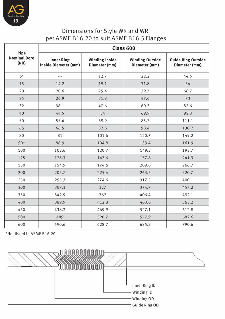
13
Dimensions for Style WR and WRI per ASME B16.20 to suit ASME B16.5 Flanges
Pipe Nominal Bore
(NB)
Class 600
Inner Ring Inside Diameter (mm)
Winding Inside Diameter (mm)
Winding Outside Diameter (mm)
Guide Ring Outside Diameter (mm)
6* --- 12.7 22.2 44.5
15 14.2 19.1 31.8 54
20 20.6 25.4 39.7 66.7
25 26.9 31.8 47.6 73
32 38.1 47.6 60.3 82.6
40 44.5 54 69.9 95.3
50 55.6 69.9 85.7 111.1
65 66.5 82.6 98.4 130.2
80 81 101.6 120.7 149.2
90* 88.9 104.8 133.4 161.9
100 102.6 120.7 149.2 193.7
125 128.3 147.6 177.8 241.3
150 154.9 174.6 209.6 266.7
200 205.7 225.4 263.5 320.7
250 255.3 274.6 317.5 400.1
300 307.3 327 374.7 457.2
350 342.9 362 406.4 492.1
400 389.9 412.8 463.6 565.2
450 438.2 469.9 527.1 612.8
500 489 520.7 577.9 682.6
600 590.6 628.7 685.8 790.6
*Not listed in ASME B16.20
Inner Ring ID
Winding ID
Winding OD
Guide Ring OD

14
Dimensions for Style WR and WRI per ASME B16.20 to suit ASME B16.5 Flanges
Pipe Nominal Bore
(NB)
Class 900
Inner Ring Inside Diameter (mm)
Winding Inside Diameter (mm)
Winding Outside Diameter (mm)
Guide Ring Outside Diameter (mm)
6* --- --- --- ---
15 14.2 19.1 31.8 63.5
20 20.6 25.4 39.7 69.9
25 26.9 31.8 47.6 79.4
32 33.3 39.7 60.3 88.9
40 41.4 47.6 69.9 98.4
50 52.3 58.7 85.7 142.9
65 63.5 69.9 98.4 165.1
80 78.7 95.3 120.7 168.3
90* 88.9 104.8 133.4 190.5
100 102.6 120.7 149.2 206.4
125 128.3 147.6 177.8 247.7
150 154.9 174.6 209.6 288.9
200 196.9 222.3 257.2 358.8
250 246.1 276.2 311.2 435
300 292.1 323.9 368.3 498.5
350 320.8 355.6 400.1 520.7
400 374.7 412.8 457.2 574.7
450 425.5 463.6 520.7 638.2
500 482.6 520.7 571.5 698.5
600** 590.6 628.7 679.5 838.2
*Not listed in ASME B16.20 **Inner Rings Should Be Used
Inner Ring ID
Winding ID
Winding OD
Guide Ring OD

15
Dimensions for Style WR and WRI per ASME B16.20 to suit ASME B16.5 Flanges
Pipe Nominal Bore
(NB)
Class 1500
Inner Ring Inside Diameter (mm)
Winding Inside Diameter (mm)
Winding Outside Diameter (mm)
Guide Ring Outside Diameter (mm)
6* --- --- --- ---
15 14.2 19.1 31.8 63.5
20 20.6 25.4 39.7 69.9
25 26.9 31.8 47.6 79.4
32 33.3 39.7 60.3 88.9
40 41.4 47.6 69.9 98.4
50 52.3 58.7 85.7 142.9
65 63.5 69.9 98.4 165.1
80 78.7 92.1 120.7 174.6
90* 88.9 104.8 133.4 187.3
100 97.8 117.5 149.2 209.6
125 124.5 142.9 177.8 254
150 147.3 171.5 209.6 282.6
200 196.9 215.9 257.2 352.4
250 246.1 266.7 311.2 435
300** 292.1 323.9 368.3 520.7
350** 320.8 362 400.1 577.9
400** 368.3 406.4 457.2 641.4
450** 425.5 463.6 520.7 704.9
500** 476.3 514.4 571.5 755.7
600** 577.9 616 679.5 901.7
*Not listed in ASME B16.20 **Inner Rings Should Be Used
Inner Ring ID
Winding ID
Winding OD
Guide Ring OD

16
Dimensions for Style WR and WRI per ASME B16.20 to suit ASME B16.5 Flanges
Pipe Nominal Bore
(NB)
Class 2500
Inner Ring Inside Diameter (mm)
Winding Inside Diameter (mm)
Winding Outside Diameter (mm)
Guide Ring Outside Diameter (mm)
6* --- --- --- ---
15 14.2 19.1 31.8 69.9
20 20.6 25.4 39.7 76.2
25 26.9 31.8 47.6 85.7
32 33.3 39.7 60.3 104.8
40 41.4 47.6 69.9 117.5
50 52.3 58.7 85.7 146.1
65 63.5 69.9 98.4 168.3
80 78.7 92.1 120.7 196.9
90* 88.9 --- --- ---
100** 97.8 117.5 149.2 235
125** 124.5 142.9 177.8 279.4
150** 147.3 171.5 209.6 317.5
200** 196.9 215.9 257.2 387.4
250** 246.1 269.9 311.2 476.3
300** 292.1 317.5 368.3 549.3
*Not listed in ASME B16.20 **Inner Rings Should Be Used
Inner Ring ID
Winding ID
Winding OD
Guide Ring OD

17
Spiral Wound Gasket Style WR and WRI Tolerances As per ASME B16.20 Specifications Winding thickness: ±0.13mm (±0.005”) measured across the metallic portion of the winding not including
the filler. Winding outside diameter:
For sizes 15NB through 200NB: ±0.8mm (±1/32”) For sizes 250NB through 600NB: +1.5mm, -0.8mm (+1/16”, -1/32”)
Winding inside diameter: For sizes 15NB through 200NB: ±0.4mm (±1/64”) For sizes 250NB through 600NB: ±0.8mm (±1/32”)
Guide ring outside diameter: ±0.8mm (±1/32”) The guide ring and inner thickness shall be between 2.97mm (0.117”) and 3.33mm (0.131”) Inner ring inside diameter:
For sizes 15NB through 80NB: ±0.8mm (±1/32”) For sizes 100NB through 600NB: ±1.5mm (±1/16”)
Marking for Standard Spiral Wounds Gaskets

18
Table for Minimum Pipe Wall Thickness that is Suitable for use with Standard Inner Rings as per ASME B16.20
Pipe Nominal
Bore (NB)
Pressure Class
150 300 400 600 900 1500 2500
15
Schedule 80 20
25
32
40
Schedule 40
50
65
80
90*
100
125
150
200
Schedule 105 Schedule 30
Schedule 80
250
300
350
400
450
500
600
General notes as per ASME B16.20. The pipe wall schedules identified represent the minimum pipe wall thickness suitable for use with inner
rings for ASME B16.5 flanges (ref. ASME B 36.10M and B36.19M). Gaskets with inner rings should be used only with socket welding, lapped, welding neck and
integral flanges. * Not listed in ASME B16.20

19
Table for Limitations on the Maximum ASME B16.5 Flange Bore for use with Standard ASME B16.20 Spiral Wound Gaskets
Pipe Nominal
Bore (NB)
Pressure Class
150 300 400 600 900¹ 1500¹ 2500¹
15
WN Flange Only²
No Flanges use Class
600
WN Flange Only
No Flanges use Class
1500 WN Flange Only²
20
25
32 SO Flange³ WN Flange²
SO Flange³ WN Flange² 40
50 SO Flange³ WN Flange, any bore
SO and WN Flange
any bore 65
80
SO and WN Flange any bore
WN Flange with SW bore
(Includes nozzle4 but excludes SO flange) WN Flange with Schedule
10S bore described in ASME B36.19M
(Includes nozzle4 but excludes SO flange)
100
125
150
200
250
300
350 WN Flange with Schedule
10S bore described in ASME B36.19M
(excludes nozzle4 and SO flanges5)
WN Flange with Schedule 80 bore (excludes nozzle4
and SO flanges5)
No Flanges
400
450
500
600
Abbreviations: SO = Slip On and Threaded WN = Weld Neck SW = Standard Wall General notes as per ASME B16.20 Specification. Inner rings are required for class 900 600NB, class 1500 300NB through 600NB and class 2500 100NB
through 300NB as per ASME B16.20. These inner rings may extend into the pipe bore a maximum of 1.5mm (1/16”) under the worst combination of maximum bore, eccentric installation and additive tolerances.
In these sizes, the gasket is suitable for a welding neck flange with a standard wall bore, if the gasket and the flanges are assembled concentrically. This also applies to a nozzle. It is the users responsibility to determine if the gasket is satisfactory for a flange or any larger bore.
Gaskets in these sizes are suitable for slip on flanges only if the gaskets and flanges are assembled concentrically.
A nozzle is a long weld neck; the bore equals the flange nominal bore.
A 600NB gasket is suitable for nozzles.

20
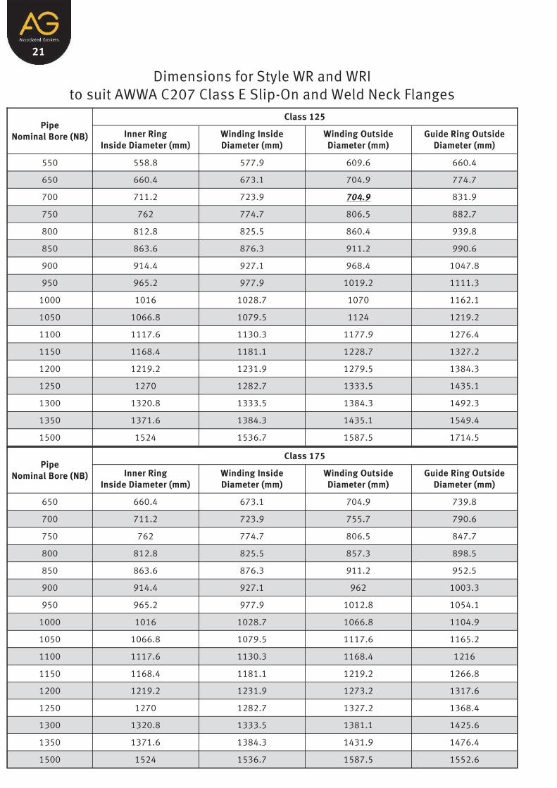
21
Dimensions for Style WR and WRI to suit AWWA C207 Class E Slip-On and Weld Neck Flanges
Pipe Nominal Bore (NB)
Class 125
Inner Ring Inside Diameter (mm)
Winding Inside Diameter (mm)
Winding Outside Diameter (mm)
Guide Ring Outside Diameter (mm)
550 558.8 577.9 609.6 660.4
650 660.4 673.1 704.9 774.7
700 711.2 723.9 704.9 831.9
750 762 774.7 806.5 882.7
800 812.8 825.5 860.4 939.8
850 863.6 876.3 911.2 990.6
900 914.4 927.1 968.4 1047.8
950 965.2 977.9 1019.2 1111.3
1000 1016 1028.7 1070 1162.1
1050 1066.8 1079.5 1124 1219.2
1100 1117.6 1130.3 1177.9 1276.4
1150 1168.4 1181.1 1228.7 1327.2
1200 1219.2 1231.9 1279.5 1384.3
1250 1270 1282.7 1333.5 1435.1
1300 1320.8 1333.5 1384.3 1492.3
1350 1371.6 1384.3 1435.1 1549.4
1500 1524 1536.7 1587.5 1714.5
Pipe Nominal Bore (NB)
Class 175
Inner Ring Inside Diameter (mm)
Winding Inside Diameter (mm)
Winding Outside Diameter (mm)
Guide Ring Outside Diameter (mm)
650 660.4 673.1 704.9 739.8
700 711.2 723.9 755.7 790.6
750 762 774.7 806.5 847.7
800 812.8 825.5 857.3 898.5
850 863.6 876.3 911.2 952.5
900 914.4 927.1 962 1003.3
950 965.2 977.9 1012.8 1054.1
1000 1016 1028.7 1066.8 1104.9
1050 1066.8 1079.5 1117.6 1165.2
1100 1117.6 1130.3 1168.4 1216
1150 1168.4 1181.1 1219.2 1266.8
1200 1219.2 1231.9 1273.2 1317.6
1250 1270 1282.7 1327.2 1368.4
1300 1320.8 1333.5 1381.1 1425.6
1350 1371.6 1384.3 1431.9 1476.4
1500 1524 1536.7 1587.5 1552.6

22
Dimensions for Style WR and WRI to suit AWWA C207 Class E Slip-On and Weld Neck Flanges
Pipe Nominal Bore (NB)
Class 250
Inner Ring Inside Diameter (mm)
Winding Inside Diameter (mm)
Winding Outside Diameter (mm)
Guide Ring Outside Diameter (mm)
650 660.4 673.1 704.9 831.9
700 711.2 723.9 755.7 895.4
750 762 774.7 806.5 952.5
800 812.8 825.5 860.4 1009.7
850 863.6 876.3 911.2 1060.5
900 914.4 927.1 968.4 1117.6
950 965.2 977.9 1019.2 1168.4
1000 1016 1028.7 1070 1225.6
1050 1066.8 1079.5 1124 1289.1
1100 1117.6 1130.3 1177.9 1346.2
1150 1168.4 1181.1 1228.7 1403.4
1200 1219.2 1231.9 1279.5 1492.3
Pipe Nominal Bore (NB)
Class 350
Inner Ring Inside Diameter (mm)
Winding Inside Diameter (mm)
Winding Outside Diameter (mm)
Guide Ring Outside Diameter (mm)
650 660.4 673.1 704.9 752.5
700 711.2 723.9 755.7 803.3
750 762 774.7 806.5 860.4
800 812.8 825.5 860.4 911.2
850 863.6 876.3 911.2 962
900 914.4 927.1 968.4 1025.5
950 965.2 977.9 1019.2 1076.3
1000 1016 1028.7 1070 1127.1
1050 1066.8 1079.5 1124 1184.3
1100 1117.6 1130.3 1177.9 1244.6
1150 1168.4 1181.1 1228.7 1295.4
1200 1219.2 1231.9 1279.5 1346.2
1300 1320.8 1333.5 1378 1457.3
1350 1371.6 1384.3 1435.1 1508.1
1500 1524 1536.7 1587.5 1660.5
1650 1676.4 1689.1 1739.9 1841.5

23
Dimensions for Style WR and WRI as per ASME B16.20 to suit ASME B16.47 Series A or MSS-SP-44 Flanges
Pipe Nominal Bore
(NB)
Class 150
Inner Ring Inside Diameter (mm)
Winding Inside Diameter (mm)
Winding Outside Diameter (mm)
Guide Ring Outside Diameter (mm)
550* --- 577.9 609.6 660.4
650 654.1 673.1 704.9 774.7
700 704.9 723.9 755.7 831.9
750 755.7 774.7 806.5 882.7
800 806.5 825.5 860.4 939.8
850 857.3 876.3 911.2 990.6
900 908.1 927.1 968.4 1047.8
950 958.9 977.9 1019.2 1111.3
1000 1009.7 1028.7 1070 1162.1
1050 1060.5 1079.5 1124 1219.2
1100 1111.3 1130.3 1177.9 1276.4
1150 1162.1 1181.1 1228.7 1327.2
1200 1212.9 1231.9 1279.5 1384.3
1250 1263.7 1282.7 1333.5 1435.1
1300 1314.5 1333.5 1384.3 1492.3
1350 1358.9 1384.3 1435.1 1549.4
1400 1409.7 1435.1 1485.9 1606.6
1450 1460.5 1485.9 1536.7 1663.7
1500 1511.3 1536.7 1587.5 1714.5
*Not listed in ASME B16.20
Inner Ring ID
Winding ID
Winding OD
Guide Ring OD

24
Dimensions for Style WR and WRI as per ASME B16.20 to suit ASME B16.47 Series A or MSS-SP-44 Flanges
Pipe Nominal Bore
(NB)
Class 300
Inner Ring Inside Diameter (mm)
Winding Inside Diameter (mm)
Winding Outside Diameter (mm)
Guide Ring Outside Diameter (mm)
550* --- 577.9 628.7 704.9
650 654.1 685.8 736.6 835
700 704.9 736.6 787.4 898.5
750 755.7 793.8 844.6 952.5
800 806.5 850.9 901.7 1006.5
850 857.3 901.7 952.5 1057.3
900 908.1 955.7 1006.5 1117.6
950 952.5 977.9 1016 1054.1
1000 1003.3 1022.4 1070 1114.4
1050 1054.1 1073.2 1120.8 1165.2
1100 1104.9 1130.3 1181.1 1219.2
1150 1152.7 1177.9 1228.7 1273.2
1200 1209.8 1235.1 1285.9 1324
1250 1244.6 1295.4 1346.2 1378
1300 1320.8 1346.2 1397 1428.8
1350 1352.6 1403.4 1454.2 1492.3
1400 1403.4 1454.2 1505 1543.1
1450 1447.8 1511.3 1562.1 1593.9
1500 1524.0 1562.1 1612.9 1644.7
*Not listed in ASME B16.20
Inner Ring ID
Winding ID
Winding OD
Guide Ring OD
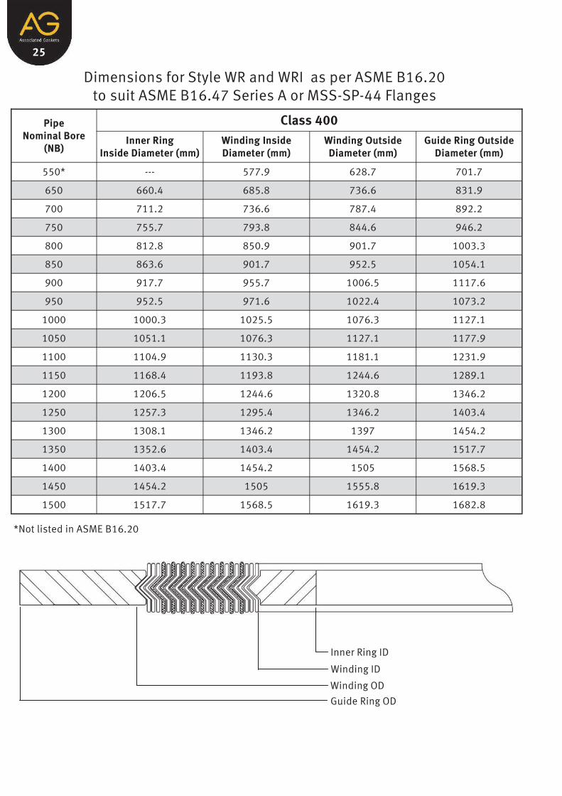
25
Dimensions for Style WR and WRI as per ASME B16.20 to suit ASME B16.47 Series A or MSS-SP-44 Flanges
Pipe Nominal Bore
(NB)
Class 400
Inner Ring Inside Diameter (mm)
Winding Inside Diameter (mm)
Winding Outside Diameter (mm)
Guide Ring Outside Diameter (mm)
550* --- 577.9 628.7 701.7
650 660.4 685.8 736.6 831.9
700 711.2 736.6 787.4 892.2
750 755.7 793.8 844.6 946.2
800 812.8 850.9 901.7 1003.3
850 863.6 901.7 952.5 1054.1
900 917.7 955.7 1006.5 1117.6
950 952.5 971.6 1022.4 1073.2
1000 1000.3 1025.5 1076.3 1127.1
1050 1051.1 1076.3 1127.1 1177.9
1100 1104.9 1130.3 1181.1 1231.9
1150 1168.4 1193.8 1244.6 1289.1
1200 1206.5 1244.6 1320.8 1346.2
1250 1257.3 1295.4 1346.2 1403.4
1300 1308.1 1346.2 1397 1454.2
1350 1352.6 1403.4 1454.2 1517.7
1400 1403.4 1454.2 1505 1568.5
1450 1454.2 1505 1555.8 1619.3
1500 1517.7 1568.5 1619.3 1682.8
*Not listed in ASME B16.20
Inner Ring ID
Winding ID
Winding OD
Guide Ring OD

26
Dimensions for Style WR and WRI as per ASME B16.20 to suit ASME B16.47 Series A or MSS-SP-44 Flanges
Pipe Nominal Bore
(NB)
Class 600
Inner Ring Inside Diameter (mm)
Winding Inside Diameter (mm)
Winding Outside Diameter (mm)
Guide Ring Outside Diameter (mm)
550* --- 577.9 628.7 733.4
650 647.7 685.8 736.6 866.8
700 698.5 736.6 787.4 914.4
750 755.7 793.8 844.6 971.6
800 812.8 850.9 901.7 1022.4
850 863.6 901.7 952.5 1073.2
900 917.7 955.7 1006.5 1130.3
950 952.5 990.6 1041.4 1104.9
1000 1009.7 1047.8 1098.6 1155.7
1050 1066.8 1104.9 1155.7 1219.2
1100 1111.3 1162.1 1212.9 1270
1150 1162.1 1212.9 1263.7 1327.2
1200 1219.2 1270 1320.8 1390.7
1250 1270 1320.8 1371.6 1447.8
1300 1320.8 1371.6 1422.4 1498.6
1350 1378 1428.8 1479.6 1555.8
1400 1428.8 1479.6 1530.4 1612.9
1450 1473.2 1536.7 1587.5 1663.7
1500 1530.4 1593.9 1644.7 1733.6
*Not listed in ASME B16.20
Inner Ring ID
Winding ID
Winding OD
Guide Ring OD

27
Dimensions for Style WR and WRI as per ASME B16.20 to suit ASME B16.47 Series A or MSS-SP-44 Flanges
Pipe Nominal Bore
(NB)
Class 900
Inner Ring Inside Diameter (mm)**
Winding Inside Diameter (mm)
Winding Outside Diameter (mm)
Guide Ring Outside Diameter (mm)
550* --- 616 685.8 838.2
650 660.4 685.8 736.6 882.7
700 711.2 736.6 787.4 946.2
750 768.4 793.8 844.6 1009.7
800 812.8 850.9 901.7 1073.2
850 863.6 901.7 952.5 1136.7
900 920.8 958.9 1009.7 1200.2
950 1009.7 1035.1 1085.9 1200.2
1000 1060.5 1098.6 1149.4 1251
1050 1111.3 1149.4 1200.2 1301.8
1100 1155.7 1206.5 1257.3 1368.4
1150 1219.2 1270 1320.8 1435.1
1200 1270 1320.8 1371.6 1485.9
*Not listed in ASME B16.20 ** Inner Rings are Required
Tolerances for Large Spiral Wounds Gaskets as per ASME B16.20 To be used with ASME B16.47 Series A Flanges Winding thickness: ±0.13mm (±0.005”) measured across the metallic portion of the winding not including
the filler. Winding outside diameter:
For sizes 650NB through 1500NB: ±1.5mm (±1/16”)
Winding inside diameter: For sizes 650NB through 850NB: ±0.8mm (±1/32”) For sizes 900NB through 1500NB: ±1.3mm (±3/64”)
Guide ring outside diameter: ±0.8mm (±1/32”) The guide ring and inner thickness shall be between 2.97mm (0.117”) and 3.33mm (0.131”) Inner ring inside diameter: ±3mm (±1/8”)
These inner rings are suitable for use with pipe walls 9.53mm (0.38”) or thicker.

28
Dimensions for Style WR and WRI as per ASME B16.20 to suit ASME B16.47 Series B or API-605 Flanges
Pipe Nominal Bore
(NB)
Class 150
Inner Ring Inside Diameter (mm)
Winding Inside Diameter (mm)
Winding Outside Diameter (mm)
Guide Ring Outside Diameter (mm)
650 654.05 673.1 698.5 725.5
700 704.9 723.9 749.3 776.3
750 755.7 774.7 800.1 827.1
800 806.5 825.5 850.9 881.1
850 857.3 876.3 908.1 935
900 908.1 927.1 958.9 987.4
950 958.9 974.7 1009.7 1044.6
1000 1009.7 1022.4 1063.6 1095.4
1050 1060.5 1079.5 1114.4 1146.2
1100 1111.3 1124 1165.2 1197
1150 1162.1 1181.1 1224 1255.7
1200 1212.9 1231.9 1270 1306.5
1250 1263.7 1282.7 1325.6 1357.3
1300 1314.5 1333.5 1376.4 1408.1
1350 1365.3 1384.3 1422.4 1463.7
1400 1422.4 1444.6 1478 1514.5
1450 1478 1500.6 1528.8 1579.6
1500 1535.2 1557.3 1585.9 1630.4
Inner Ring ID
Winding ID
Winding OD
Guide Ring OD

29
Dimensions for Style WR and WRI as per ASME B16.20 to suit ASME B16.47 Series B or API-605 Flanges
Pipe Nominal Bore
(NB)
Class 300
Inner Ring Inside Diameter (mm)
Winding Inside Diameter (mm)
Winding Outside Diameter (mm)
Guide Ring Outside Diameter (mm)
650 654.05 673.1 711.2 771.5
700 704.9 723.9 762 825.5
750 755.7 774.7 812.8 885.8
800 806.5 825.5 863.6 939.8
850 857.3 876.3 914.4 993.8
900 908.1 927.1 965.2 1047.8
950 971.6 1009.7 1047.8 1098.6
1000 1022.4 1060.5 1098.6 1149.4
1050 1085.9 1111.3 1149.4 1200.2
1100 1124 1162.1 1200.2 1251
1150 1178.1 1216 1254.3 1317.6
1200 1155.7 1263.7 1311.3 1368.4
1250 1267 1317.6 1355.7 1419.2
1300 1317.8 1368.4 1406.5 1470
1350 1365.3 1403.4 1454.2 1530.4
1400 1428.8 1479.6 1524 1593.9
1450 1484.4 1535.1 1573.2 1655.8
1500 1557.3 1589.1 1630.4 1706.6
Inner Ring ID
Winding ID
Winding OD
Guide Ring OD
30
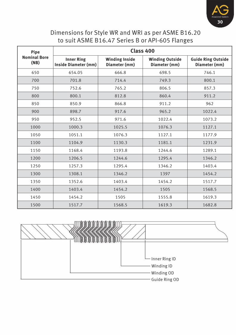
Dimensions for Style WR and WRI as per ASME B16.20 to suit ASME B16.47 Series B or API-605 Flanges
Pipe Nominal Bore
(NB)
Class 400
Inner Ring Inside Diameter (mm)
Winding Inside Diameter (mm)
Winding Outside Diameter (mm)
Guide Ring Outside Diameter (mm)
650 654.05 666.8 698.5 746.1
700 701.8 714.4 749.3 800.1
750 752.6 765.2 806.5 857.3
800 800.1 812.8 860.4 911.2
850 850.9 866.8 911.2 962
900 898.7 917.6 965.2 1022.4
950 952.5 971.6 1022.4 1073.2
1000 1000.3 1025.5 1076.3 1127.1
1050 1051.1 1076.3 1127.1 1177.9
1100 1104.9 1130.3 1181.1 1231.9
1150 1168.4 1193.8 1244.6 1289.1
1200 1206.5 1244.6 1295.4 1346.2
1250 1257.3 1295.4 1346.2 1403.4
1300 1308.1 1346.2 1397 1454.2
1350 1352.6 1403.4 1454.2 1517.7
1400 1403.4 1454.2 1505 1568.5
1450 1454.2 1505 1555.8 1619.3
1500 1517.7 1568.5 1619.3 1682.8
Inner Ring ID
Winding ID
Winding OD
Guide Ring OD

31
Dimensions for Style WR and WRI as per ASME B16.20 to suit ASME B16.47 Series B or API-605 Flanges
Pipe Nominal Bore
(NB)
Class 600
Inner Ring Inside Diameter (mm)
Winding Inside Diameter (mm)
Winding Outside Diameter (mm)
Guide Ring Outside Diameter (mm)
650 644.65 663.6 714.4 765.2
700 685.8 704.9 755.7 819.2
750 752.6 777.9 828.7 879.5
800 793.8 831.9 882.7 933.5
850 850.9 889 939.8 997
900 901.7 939.8 990.6 1047.8
950 952.5 990.6 1041.4 1104.9
1000 1009.7 1047.8 1098.6 1155.7
1050 1066.8 1104.9 1155.7 1219.2
1100 1111.3 1162.1 1212.9 1270
1150 1162.1 1212.9 1263.7 1327.2
1200 1219.2 1270 1320.8 1390.7
1250 1270 1320.8 1371.6 1447.8
1300 1320.8 1371.6 1422.4 1498.6
1350 1378 1428.8 1479.6 1555.8
1400 1428.8 1479.6 1530.4 1612.9
1450 1473.2 1536.7 1587.5 1663.7
1500 1530.4 1593.9 1644.7 1733.6
Inner Ring ID
Winding ID
Winding OD
Guide Ring OD

32
Dimensions for Style WR and WRI as per ASME B16.20 to suit ASME B16.47 Series B or API-605 Flanges
Pipe Nominal Bore
(NB)
Class 900
Inner Ring Inside Diameter (mm)*
Winding Inside Diameter (mm)
Winding Outside Diameter (mm)
Guide Ring Outside Diameter (mm)
650 666.8 692.2 749.3 838.2
700 717.6 743 800.1 901.7
750 781.1 806.5 857.3 958.9
800 838.2 863.6 914.4 1016
850 895.4 920.8 971.6 1073.2
900 920.8 946.2 997 1124
950 1009.7 1035.1 1085.9 1200.2
1000 1060.5 1098.6 1149.4 1251
1050 1111.3 1149.4 1200.2 1301.8
1100 1155.7 1206.5 1257.3 1368.4
1150 1219.2 1270 1320.8 1435.1
1200 1270 1320.8 1371.6 1485.9
* Inner Rings are Required
Tolerances for Large Spiral Wounds Gaskets as per ASME B16.20 To be used with ASME B16.47 Series B Flanges Winding thickness: ±0.13mm (±0.005”) measured across the metallic portion of the winding not including
the filler. Winding outside diameter:
For sizes 650NB through 1500NB: ±1.5mm (±1/16”)
Winding inside diameter: For sizes 650NB through 850NB: ±0.8mm (±1/32”) For sizes 900NB through 1500NB: ±1.3mm (±3/64”)
Guide ring outside diameter: ±0.8mm (±1/32”) The guide ring and inner thickness shall be between 2.97mm (0.117”) and 3.33mm (0.131”) Inner ring inside diameter: ±3mm (±1/8”)
These inner rings are suitable for use with pipe walls 9.53mm (0.38”) or thicker.

33
Dimensions for Style WR and WRI to suit ASME/ANSI B16.5 and Slip-On Flanges
Pipe Nominal Bore
(NB)
Class 150
Inner Ring Inside Diameter (mm)
Winding Inside Diameter (mm)
Winding Outside Diameter (mm)
Guide Ring Outside Diameter (mm)
6 --- 14.3 22.2 44.5
15 14.3 23.8 31.8 47.6
20 20.6 30.2 39.7 57.2
25 27 36.5 47.6 66.7
32 34.9 47.6 60.3 76.2
40 41.3 54 69.9 85.7
Pipe Nominal Bore
(NB)
Class 300
Inner Ring Inside Diameter (mm)
Winding Inside Diameter (mm)
Winding Outside Diameter (mm)
Guide Ring Outside Diameter (mm)
6 --- 14.3 22.2 44.5
15 14.3 23.8 31.8 54
20 20.6 30.2 39.7 66.7
25 27 36.5 47.6 73
32 34.9 47.6 60.3 82.6
40 41.3 54 69.9 95.3
Pipe Nominal Bore
(NB)
Class 400
Inner Ring Inside Diameter (mm)
Winding Inside Diameter (mm)
Winding Outside Diameter (mm)
Guide Ring Outside Diameter (mm)
6 --- 14.3 22.2 44.5
15 14.3 23.8 31.8 54
20 20.6 30.2 39.7 66.7
25 27 36.5 47.6 73
32 34.9 47.6 60.3 82.6
40 41.3 54 69.9 95.3
Pipe Nominal Bore
(NB)
Class 600
Inner Ring Inside Diameter (mm)
Winding Inside Diameter (mm)
Winding Outside Diameter (mm)
Guide Ring Outside Diameter (mm)
6 --- 14.3 22.2 44.5
15 14.3 23.8 31.8 54
20 20.6 30.2 39.7 66.7
25 27 36.5 47.6 73
32 34.9 47.6 60.3 82.6
40 41.3 54 69.9 95.3

34
Dimensions for Style WR and WRI to suit ASME/ANSI B16.5 and Slip-On Flanges
Standard spiral wound gasket dimensions are not compatible with slip-on flanges, threaded flanges or lap joint flanges in certain sizes due to the larger bore on slip-on flanges.
Pipe Nominal Bore
(NB)
Class 900
Inner Ring Inside Diameter (mm)
Winding Inside Diameter (mm)
Winding Outside Diameter (mm)
Guide Ring Outside Diameter (mm)
15 14.3 23.8 31.8 63.5
20 20.6 30.2 39.7 69.9
25 27 36.5 47.6 79.4
32 34.9 47.6 60.3 88.9
40 41.3 54 69.9 98.4
Pipe Nominal Bore
(NB)
Class 1500
Inner Ring Inside Diameter (mm)
Winding Inside Diameter (mm)
Winding Outside Diameter (mm)
Guide Ring Outside Diameter (mm)
15 14.3 23.8 31.8 63.5
20 20.6 30.2 39.7 69.9
25 27 36.5 47.6 79.4
32 34.9 47.6 60.3 88.9
40 41.3 54 69.9 98.4

35
Dimensions for Style WR and WRI to suit Type A and B Flanges as per EN 1514-2
DN
Inner Ring Inside
Diameter (mm)
Winding Inside
Diameter (mm)
Winding Outside
Diameter (mm)
Guide Ring Outside
Diameter (mm) Guide Ring Outside Diameter (mm)
PN10, PN25, PN40
PN63, PN100, PN160
PN 10
PN 25
PN 40
PN 63
PN 100
PN 160
10 18 24 34 34 46 56
15 23 29 39 39 51 61
20 28 34 46 --- 61 ---
25 35 41 53 53 71 82
32 43 49 61 --- 82 ---
40 50 56 68 68 92 103
50 61 70 86 86 107 113 119
65 77 86 102 106 127 137 143
80 90 99 115 119 142 148 154
100 115 127 143 147 162 168 174 180
125 140 152 172 176 192 194 210 217
150 167 179 199 203 217 224 247 257
200 216 228 248 252 272 284 290 309 324
250 267 279 303 307 327 340 352 364 391 388
300 318 330 354 358 377 400 417 424 458 458
350 360 376 400 404 437 457 474 486 512 ---
400 410 422 450 456 488 514 546 543 572 ---
500 510 522 550 556 593 624 628 657 704 ---
600 610 622 650 656 695 731 747 764 813 ---
700 710 722 756 762 810 833 852 879 950 ---
800 810 830 864 870 917 942 974 988 --- ---
900 910 930 964 970 1017 1042 1084 1108 --- ---
1000 1010 1030 1074 1080 1124 1154 1194 --- --- ---
Inner Ring ID
Winding ID
Winding OD
Guide Ring OD

36
Dimensions for Style WR to suit British Standard BS 10 Weld Neck and Slip-On Flanges Table D and E
Pipe Nominal Bore
(NB)
Winding Outside Diameter (mm)
Gasket Outside Diameter (mm) Winding Inside Diameter (mm) Table D Table E
15 26.2 37.3 54 54
20 31.8 42.9 60.3 60.3
25 39.7 52.4 69.9 69.9
32 47.6 60.3 74.6 74.6
40 54 66.7 85.8 85.8
50 66.7 79.4 98.5 98.5
65 82.6 98.5 111.2 111.2
80 96.9 112.8 130.2 130.2
90 109.6 125.5 149.3 149.3
100 123.9 139.7 161.9 161.9
115 136.6 152.4 174.6 174.6
125 149.2 165.1 193.6 193.6
150 174.6 190.5 219 215.9
175 200 219 244.5 241.3
200 225.4 244.5 276.2 273
225 250.8 269.9 308 304.8
250 276.3 295.3 336.6 336.6
275 301.6 320.7 362 362
300 327 349.3 387.4 384.2
325 368.3 390.6 419.1 415.9
350 393.7 416 447.7 447.7
375 419.1 441.3 473 473
400 444.5 466.7 498.5 498.5
425 473 498.5 530.3 527
450 498.5 523.9 562 562
475 523.9 549.3 587.4 587.4
500 549.3 574.7 619.2 619.2
525 574.7 603.3 651 547.7
550 600 628.7 673.1 673.1
575 625.5 654 698.5 698.5
600 650.9 679.5 730.3 728.7

37
Dimensions for Style WR to suit British Standard BS 10 Weld Neck and Slip-On Flanges Table F, H, J, K and R
Pipe Nominal
Bore (NB)
Winding Inside
Diameter (mm)
Winding Outside
Diameter (mm)
Guide Ring Outside Diameter (mm)
Table F Table H Table J Table K Table R
15 26.2 38.9 54 66.7 66.7 66.7 66.7
20 31.8 44.5 60.3 66.7 66.7 66.7 66.7
25 39.7 55.6 71.5 71.5 71.5 79.4 79.4
32 47.6 63.5 82.6 82.6 82.6 82.6 82.6
40 54 69.9 88.9 88.9 88.9 95.3 95.3
50 66.7 82.6 111.2 111.2 108 111.2 111.2
65 82.6 101.6 130.2 130.2 127 127 127
80 96.9 115.9 149.3 149.3 146 146 146
90 109.6 128.6 162 162 158.9 162 162
100 123.9 142.9 174.7 174.7 171.5 174.7 174.7
115 136.6 158.9 190.5 190.5 187.4 187.4 187.4
125 149.2 171.5 215.9 215.9 212.8 212.8 212.8
150 174.6 196.9 241.3 241.3 238.2 238.2 238.2
175 200 225.4 273 273 269.9 266.7 266.7
200 225.4 250.9 304.8 304.8 301.7 292.1 298.5
225 250.8 276.3 333.4 333.4 330.2 330.2 330.2
250 279.4 304.8 358.8 358.8 355.6 355.6 362
275 304.8 330.2 384.2 384.2 381 384.2 403.3
300 330.2 358.7 416 416 412.8 403.3 428.7
325 362 390.6 444.5 444.5 441.4 451 463.6
350 387.4 415.9 470 470 466.8 476.3 495.3
375 412.8 441.4 495.3 495.3 492.2 508 520.7
400 444.5 476.3 527 527 523.9 533.4 552.5
425 469.9 504.9 558.8 558.8 555.7 565.2 577.9
450 495.3 530.3 581 581 577.9 619.2 638.2
475 523.9 562 612.3 612.3 609.6 --- ---
500 549.3 587.4 644.6 644.6 641.4 673.1 692.2
525 574.7 619.2 670 670 666.8 --- ---
550 600 644.5 695.4 695.4 692.2 730.3 755.7
575 625.5 670 723.9 723.9 720.8 --- ---
600 651 695.4 749.3 749.3 746.1 --- ---

38
Dimensions for Style WR to suit British Standard BS 10 Weld Neck and Slip-On Flanges Table S
Pipe Nominal Bore
(NB)
BS 10:1931 BS 10:1962 Guide Ring Outside
Diameter (mm) Winding Inside Diameter (mm)
Winding Outside Diameter (mm)
Winding Inside Diameter (mm)
Winding Outside Diameter (mm)
15 19.1 31.8 19.1 31.8 69.9
20 25.4 39.7 25.4 39.7 69.9
25 31.8 47.6 31.8 47.6 82.6
32 38.1 55.6 38.1 55.6 88.9
40 44.5 63.5 44.5 63.5 101.6
50 57.2 76.2 57.2 79.4 114.3
65 69.9 88.9 73 95.3 127
80 82.6 101.6 85.7 108 142.9
90 95.3 114.3 98.4 120.7 168.3
100 108 127 111.1 136.5 177.8
115 120.7 139.7 123.8 149.2 190.5
125 133.4 152.4 136.5 161.9 212.7
150 158.8 177.8 161.9 187.3 247.7
175 187.3 209.6 187.3 219.1 288.9
200 212.7 235 212.7 244.5 323.9
225 238.1 260.4 241.3 273.1 358.8
250 263.5 285.8 266.7 301.6 393.7
??? 288.9 317.5 292.1 327 435
??? 314.3 346.1 320.7 355.6 469.9
??? 339.7 371.5 346.1 384.2 501.7
??? 365.1 400.1 371.5 409.6 539.8
??? 390.5 428.6 400.1 438.2 581
??? 415.9 454 425.5 466.7 616
Winding ID
Winding OD
Guide Ring OD
39
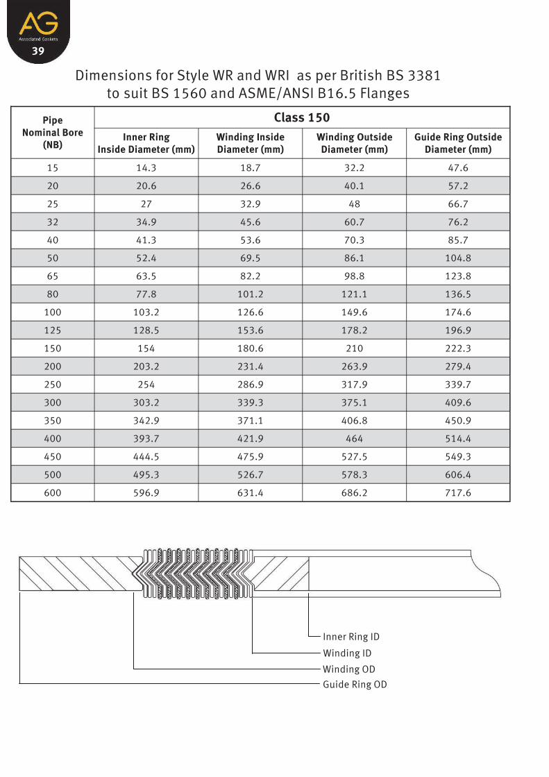
Dimensions for Style WR and WRI as per British BS 3381 to suit BS 1560 and ASME/ANSI B16.5 Flanges
Pipe Nominal Bore
(NB)
Class 150
Inner Ring Inside Diameter (mm)
Winding Inside Diameter (mm)
Winding Outside Diameter (mm)
Guide Ring Outside Diameter (mm)
15 14.3 18.7 32.2 47.6
20 20.6 26.6 40.1 57.2
25 27 32.9 48 66.7
32 34.9 45.6 60.7 76.2
40 41.3 53.6 70.3 85.7
50 52.4 69.5 86.1 104.8
65 63.5 82.2 98.8 123.8
80 77.8 101.2 121.1 136.5
100 103.2 126.6 149.6 174.6
125 128.5 153.6 178.2 196.9
150 154 180.6 210 222.3
200 203.2 231.4 263.9 279.4
250 254 286.9 317.9 339.7
300 303.2 339.3 375.1 409.6
350 342.9 371.1 406.8 450.9
400 393.7 421.9 464 514.4
450 444.5 475.9 527.5 549.3
500 495.3 526.7 578.3 606.4
600 596.9 631.4 686.2 717.6
Inner Ring ID
Winding ID
Winding OD
Guide Ring OD

40
Dimensions for Style WR and WRI as per British BS 3381 to suit BS 1560 and ASME/ANSI B16.5 Flanges
Pipe Nominal Bore
(NB)
Class 300
Inner Ring Inside Diameter (mm)
Winding Inside Diameter (mm)
Winding Outside Diameter (mm)
Guide Ring Outside Diameter (mm)
15 14.3 18.7 32.2 54
20 20.6 25 40.1 66.7
25 27 31.4 48 73
32 34.9 44.1 60.7 82.6
40 41.3 50.4 70.3 95.3
50 52.4 66.3 86.1 111.1
65 63.5 79 98.8 130.2
80 77.8 94.9 121.1 149.2
100 103.2 120.3 149.6 181
125 128.5 147.2 178.2 215.9
150 154 174.2 210 250.8
200 203.2 225 263.9 308
250 254 280.6 317.9 362
300 303.2 333 375.1 422.3
350 342.9 364.7 406.8 485.8
400 393.7 415.5 464 539.8
450 444.5 469.5 527.5 596.9
500 495.3 520.3 578.3 654.1
600 596.9 625.1 686.2 774.7
Inner Ring ID
Winding ID
Winding OD
Guide Ring OD

41
Dimensions for Style WR and WRI as per British BS 3381 to suit BS 1560 and ASME/ANSI B16.5 Flanges
Pipe Nominal Bore
(NB)
Class 600
Inner Ring Inside Diameter (mm)
Winding Inside Diameter (mm)
Winding Outside Diameter (mm)
Guide Ring Outside Diameter (mm)
15 14.3 18.7 32.2 54
20 20.6 25 40.1 66.7
25 27 31.4 48 73
32 34.9 44.1 60.7 82.6
40 41.3 50.4 70.3 95.3
50 52.4 66.3 86.1 111.1
65 63.5 79 98.8 130.2
80 77.8 94.9 121.1 149.2
100 103.2 120.3 149.6 193.7
125 128.5 147.2 178.2 241.3
150 154 174.2 210 266.7
200 203.2 225 263.9 320.7
250 254 280.6 317.9 400.1
300 303.2 333 375.1 457.2
350 342.9 364.7 406.8 492.1
400 393.7 415.5 464 565.2
450 444.5 469.5 527.5 612.8
500 495.3 520.3 578.3 682.6
600 596.9 625.1 686.2 790.6
Inner Ring ID
Winding ID
Winding OD
Guide Ring OD

42
Dimensions for Style WR and WRI as per British BS 3381 to suit BS 1560 and ASME/ANSI B16.5 Flanges
Pipe Nominal Bore
(NB)
Class 900
Inner Ring Inside Diameter (mm)
Winding Inside Diameter (mm)
Winding Outside Diameter (mm)
Guide Ring Outside Diameter (mm)
15 14.3 18.7 32.2 63.5
20 20.6 25 40.1 69.9
25 27 31.4 48 79.4
32 34.9 44.1 60.7 88.9
40 41.3 50.4 70.3 98.4
50 52.4 66.3 86.1 142.9
65 63.5 79 98.8 165.1
80 77.8 94.9 121.1 168.3
100 103.2 120.3 149.6 206.4
125 128.5 147.2 178.2 247.7
150 154 174.2 210 288.9
200 203.2 225 263.9 358.8
250 254 280.6 317.9 435
300 303.2 333 375.1 498.5
350 342.9 364.7 406.8 520.7
400 393.7 415.5 464 574.7
450 444.5 469.5 527.5 638.2
500 495.3 520.3 578.3 698.5
600 596.9 625.1 686.2 838.2
Inner Ring ID
Winding ID
Winding OD
Guide Ring OD

43
Dimensions for Style WR and WRI as per British BS 3381 to suit BS 1560 and ASME/ANSI B16.5 Flanges
Pipe Nominal Bore
(NB)
Class 1500
Inner Ring Inside Diameter (mm)
Winding Inside Diameter (mm)
Winding Outside Diameter (mm)
Guide Ring Outside Diameter (mm)
15 14.3 18.7 32.2 63.5
20 20.6 25 40.1 69.9
25 27 31.4 48 79.4
32 34.9 44.1 60.7 88.9
40 41.3 50.4 70.3 98.4
50 52.4 66.3 86.1 142.9
65 63.5 79 98.8 165.1
80 77.8 94.9 121.1 174.6
100 103.2 120.3 149.6 209.6
125 128.5 147.2 178.2 254
150 154 174.2 210 282.6
200 203.2 225 263.9 352.4
250 254 280.6 317.9 435
300 303.2 333 375.1 520.7
350 342.9 364.7 406.8 577.9
400 393.7 415.5 464 641.4
450 444.5 469.5 527.5 704.9
500 495.3 520.3 578.3 755.7
600 596.9 625.1 686.2 901.7
Inner Ring ID
Winding ID
Winding OD
Guide Ring OD

44
Dimensions for Style WR and WRI as per British BS 3381 to suit BS 1560 and ASME/ANSI B16.5 Flanges
Pipe Nominal Bore
(NB)
Class 2500
Inner Ring Inside Diameter (mm)
Winding Inside Diameter (mm)
Winding Outside Diameter (mm)
Guide Ring Outside Diameter (mm)
15 14.3 18.7 32.2 69.9
20 20.6 25 40.1 76.2
25 27 31.4 48 85.7
32 34.9 39.3 60.7 104.8
40 41.3 47.2 70.3 117.5
50 52.4 58.3 86.1 146.1
65 63.5 69.5 98.8 168.3
80 77.8 91.7 121.1 196.9
100 103.2 117.1 149.6 235
125 128.5 142.5 178.2 279.4
150 154 171.1 210 317.5
200 203.2 215.5 263.9 387.4
250 254 269.5 317.9 476.3
300 303.2 323.5 375.1 549.6
Inner Ring ID
Winding ID
Winding OD
Guide Ring OD

45
Dimensions for Style WR to suit French Standard NF-M-87621
Pipe Nominal
Bore
Class 150 Class 300 Class 600
Winding Inside
Diameter (mm)
Winding Outside
Diameter (mm)
Guide Ring
Outside Diameter
(mm)
Winding Inside
Diameter (mm)
Winding Outside
Diameter (mm)
Guide Ring
Outside Diameter
(mm)
Winding Inside
Diameter (mm)
Winding Outside
Diameter (mm)
Guide Ring
Outside Diameter
(mm)
15 19 29 47 19 29 29 54 19 54
20 25 37 57 25 37 37 66 25 66
25 32 44 66 32 44 44 73 32 73
32 48 57 76 48 57 57 82 48 82
40 54 67 85 54 67 67 95 54 95
50 70 82 104 70 82 82 111 70 111
65 83 95 124 ??? 95 95 130 130 83
80 102 117 136 102 117 117 149 149 102
100 127 146 174 127 146 146 193 181 120
125 156 176 197 156 176 216 176 241 148
150 183 206 222 183 206 251 206 266 175
200 233 260 279 233 260 308 260 320 225
250 287 314 339 287 314 362 275 314 400
300 340 371 409 340 371 422 327 371 457
350 372 403 451 372 403 485 362 403 492
400 422 460 514 422 460 539 413 460 565
450 475 524 549 475 524 597 470 524 612
500 525 575 606 525 575 654 521 575 682
600 629 682 717 629 682 774 629 682 790
Winding ID
Winding OD
Guide Ring OD

46
Dimensions for Style WR to suit French Standard NF-M-87621
Pipe Nominal
Bore
Class 900 Class 1500 Class 2500
Winding Inside
Diameter (mm)
Winding Outside
Diameter (mm)
Guide Ring
Outside Diameter
(mm)
Winding Inside
Diameter (mm)
Winding Outside
Diameter (mm)
Guide Ring
Outside Diameter
(mm)
Winding Inside
Diameter (mm)
Winding Outside
Diameter (mm)
Guide Ring
Outside Diameter
(mm)
15 19 29 63 19 29 29 63 19 70
20 25 37 70 25 37 37 70 25 76
25 32 44 79 32 44 44 79 32 86
32 40 57 89 40 57 57 89 40 105
40 48 67 98 48 67 67 98 48 117
50 59 82 143 59 82 82 143 59 146
65 70 95 165 70 95 95 168 165 70
80 95 117 168 92 117 117 197 174 92
100 120 146 206 118 146 146 235 209 118
125 148 176 247 143 176 254 176 279 143
150 175 206 289 171 206 282 206 317 171
200 225 260 359 216 260 352 260 387 216
250 275 314 435 270 314 435 270 314 476
300 327 371 498 324 371 520 324 371 549
350 362 403 520 362 403 578 --- --- ---
400 413 460 574 413 460 641 --- --- ---
450 464 524 638 454 524 705 --- --- ---
500 514 575 698 514 575 756 --- --- ---
600 616 682 838 516 682 901 --- --- ---
Winding ID
Winding OD
Guide Ring OD

47
Dimensions for Style WR to suit Japanese ( JIS) Flanges Pressure Rating of 10kgf/cm²
DN Winding Inside
Diameter (mm)
Winding Outside
Diameter (mm)
Guide Ring Outside
Diameter (mm)
10 24 37 52
15 28 41 57
20 34 47 62
25 40 53 74
32 51 67 84
40 57 73 89
50 69 89 104
65 87 107 124
80 98 118 134
90 110 130 144
100 123 143 159
125 148 173 190
150 174 199 220
175 201 226 245
200 227 252 270
225 252 277 290
250 278 310 332
300 329 361 377
350 366 406 422
400 417 457 484
450 468 518 539
500 518 568 594
550 569 619 650
600 620 670 700
Winding ID
Winding OD
Guide Ring OD

48
Dimensions for Style WR and WRI to suit Japanese ( JIS) Flanges Pressure Rating of 16-20kgf/cm²
DN Winding Inside
Diameter (mm)
Winding Outside
Diameter (mm)
Guide Ring Outside
Diameter (mm)
Inner Ring Inside
Diameter (mm)
10 24 37 52 18
15 28 41 57 22
20 34 47 62 28
25 40 53 74 34
32 51 67 84 43
40 57 73 89 49
50 69 89 104 61
65 87 107 124 77
80 99 119 140 89
90 114 139 150 102
100 127 152 165 115
125 152 177 202 140
150 182 214 237 166
175 --- --- --- ---
200 233 265 282 217
225 --- --- --- ---
250 288 328 354 268
300 339 379 404 319
350 376 416 450 356
400 432 482 508 407
450 483 533 573 458
500 533 583 628 508
550 584 634 684 559
600 635 685 734 610
Inner Ring ID
Winding ID
Winding OD
Guide Ring OD

49
Dimensions for Style WR and WRI to suit Japanese ( JIS) Flanges Pressure Rating of 30kgf/cm²
Inner Ring ID
Winding ID
Winding OD
Guide Ring OD
DN Inner Ring
Inside Diameter (mm)
Winding Inside
Diameter (mm)
Winding Outside
Diameter (mm)
Guide Ring Outside
Diameter (mm)
10 18 24 37 59
15 22 28 41 64
20 28 34 47 69
25 34 40 53 79
32 43 51 67 89
40 49 57 73 100
50 61 69 89 114
65 68 78 98 140
80 80 90 110 150
90 92 102 127 162
100 104 116 141 172
125 128 140 165 207
150 153 165 197 249
200 202 218 250 294
250 251 271 311 360
300 300 320 360 418
350 336 356 396 463
400 383 403 453 524

50
Dimensions for Style WR and WRI to suit Japanese ( JIS) Flanges Pressure Rating of 40kgf/cm²
DN Inner Ring
Inside Diameter (mm)
Winding Inside
Diameter (mm)
Winding Outside
Diameter (mm)
Guide Ring Outside
Diameter (mm)
10 15 21 34 59
15 18 24 37 64
20 23 29 42 69
25 29 35 48 79
32 38 44 60 89
40 43 51 67 100
50 55 63 79 114
65 68 78 98 140
80 80 90 110 150
90 92 102 127 162
100 104 116 141 182
125 128 140 165 224
150 153 165 197 265
200 202 218 250 315
250 251 271 311 378
300 300 320 360 434
350 336 356 396 479
400 383 403 453 531
Inner Ring ID
Winding ID
Winding OD
Guide Ring OD

51
Dimensions for Style WR and WRI to suit Japanese ( JIS) Flanges Pressure Rating of 63kgf/cm²
Inner Ring ID
Winding ID
Winding OD
Guide Ring OD
DN Inner Ring
Inside Diameter (mm)
Winding Inside
Diameter (mm)
Winding Outside
Diameter (mm)
Guide Ring Outside
Diameter (mm)
10 15 21 34 64
15 18 24 37 69
20 23 29 42 75
25 29 35 48 80
32 38 44 60 90
40 43 51 67 107
50 55 63 79 125
65 68 78 98 152
80 80 90 110 162
90 92 102 127 179
100 104 116 141 194
125 128 140 165 235
150 153 165 197 275
200 202 218 250 328
250 251 271 311 394
300 300 320 360 446
350 336 356 396 488
400 383 403 453 545

52

53 Style WR-RJ and WRI-RJ Gaskets
Pipe Nominal Bore
(NB)
Class 150
Inner Ring Inside Diameter (mm)
Winding Inside Diameter (mm)
Winding Outside Diameter (mm)
Guide Ring Outside Diameter (mm)
25 Contact AG for Sizing Information
32
Inside Diameter of Inner Ring will
Depend on Bore Schedule.
34.9 46 76.2
40 41.3 54 85.7
50 54 69.9 104.8
65 69.9 84.1 123.8
80 84.1 100 136.5
100 109.5 131.8 174.6
125 134.9 157.2 196.9
150 160.3 182.6 222.3
200 209.6 233.4 279.4
250 261.9 290.5 339.7
300 309.6 344.5 409.6
350 341.3 379.4 450.9
400 388.9 430.2 514.4
450 438.2 482.6 549.3
500 485.8 536.6 606.4
600 584.2 641.4 717.6
Dimensions for Style WR-RJ and WRI-RJ to suit Raised Face to RTJ Flanges
Inner Ring ID
Winding ID
Winding OD
Guide Ring OD

54
Dimensions for Style WR-RJ and WRI-RJ to suit Raised Face to RTJ Flanges
Inner Ring ID
Winding ID
Winding OD
Guide Ring OD
Pipe Nominal Bore
(NB)
Class 300
Inner Ring Inside Diameter (mm)
Winding Inside Diameter (mm)
Winding Outside Diameter (mm)
Guide Ring Outside Diameter (mm)
15 14.3 23.8 54
Inside Diameter of Inner Ring will
Depend on Bore Schedule.
20 20.6 31.8 66.7
25 27 39.7 73
32 33.3 47.6 82.6
40 39.7 55.6 95.3
50 54 68.3 111.1
65 69.9 84.1 130.2
80 84.1 100 149.2
100 109.5 131.8 181
125 134.9 163.5 215.9
150 163.5 193.7 250.8
200 209.6 252.4 308
250 261.9 304.8 362
300 327 362 422.3
350 362 400.1 485.8
400 412.8 450.9 539.8
450 463.6 514.4 596.9
500 514.4 563.6 654.1
600 616 668.3 774.7

55
Dimensions for Style WR-RJ and WRI-RJ to suit Raised Face to RTJ Flanges
Inner Ring ID
Winding ID
Winding OD
Guide Ring OD
Pipe Nominal Bore
(NB)
Class 400
Inner Ring Inside Diameter (mm)
Winding Inside Diameter (mm)
Winding Outside Diameter (mm)
Guide Ring Outside Diameter (mm)
15 14.3 23.8 54
Inside Diameter of Inner Ring will
Depend on Bore Schedule.
20 20.6 31.8 66.7
25 27 39.7 73
32 33.3 47.6 82.6
40 39.7 55.6 95.3
50 54 68.3 111.1
65 69.9 84.1 130.2
80 84.1 100 149.2
100 109.5 131.8 177.8
125 134.9 163.5 212.7
150 163.5 193.7 247.7
200 209.6 252.4 304.8
250 261.9 304.8 358.8
300 327 362 419.1
350 362 400.1 482.6
400 412.8 450.9 536.6
450 463.6 514.4 593.7
500 514.4 563.6 647.7
600 616 668.3 768.4

56
Dimensions for Style WR-RJ and WRI-RJ to suit Raised Face to RTJ Flanges
Inner Ring ID
Winding ID
Winding OD
Guide Ring OD
Pipe Nominal Bore
(NB)
Class 600
Inner Ring Inside Diameter (mm)
Winding Inside Diameter (mm)
Winding Outside Diameter (mm)
Guide Ring Outside Diameter (mm)
15 14.3 23.8 54
Inside Diameter of Inner Ring will
Depend on Bore Schedule.
20 20.6 31.8 66.7
25 27 39.7 73
32 33.3 47.6 82.6
40 39.7 55.6 95.3
50 54 68.3 111.1
65 69.9 84.1 130.2
80 84.1 100 149.2
100 109.5 131.8 193.7
125 134.9 163.5 241.3
150 163.5 193.7 266.7
200 209.6 252.4 320.7
250 261.9 304.8 400.1
300 327 362 457.2
350 362 400.1 492.1
400 412.8 450.9 565.2
450 463.6 514.4 612.8
500 514.4 563.6 682.6
600 616 668.3 790.6
57
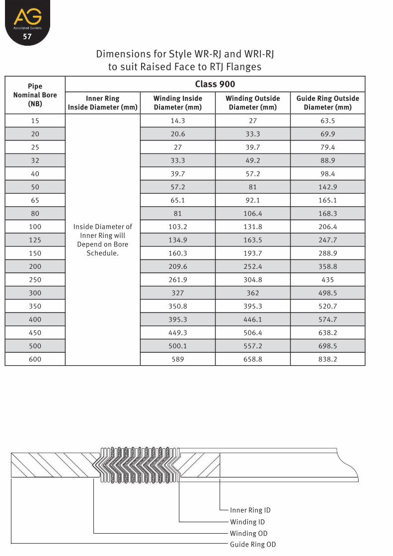
Dimensions for Style WR-RJ and WRI-RJ to suit Raised Face to RTJ Flanges
Inner Ring ID
Winding ID
Winding OD
Guide Ring OD
Pipe Nominal Bore
(NB)
Class 900
Inner Ring Inside Diameter (mm)
Winding Inside Diameter (mm)
Winding Outside Diameter (mm)
Guide Ring Outside Diameter (mm)
15 14.3 27 63.5
Inside Diameter of Inner Ring will
Depend on Bore Schedule.
20 20.6 33.3 69.9
25 27 39.7 79.4
32 33.3 49.2 88.9
40 39.7 57.2 98.4
50 57.2 81 142.9
65 65.1 92.1 165.1
80 81 106.4 168.3
100 103.2 131.8 206.4
125 134.9 163.5 247.7
150 160.3 193.7 288.9
200 209.6 252.4 358.8
250 261.9 304.8 435
300 327 362 498.5
350 350.8 395.3 520.7
400 395.3 446.1 574.7
450 449.3 506.4 638.2
500 500.1 557.2 698.5
600 589 658.8 838.2

58
Dimensions for Style WR-RJ and WRI-RJ to suit Raised Face to RTJ Flanges
Inner Ring ID
Winding ID
Winding OD
Guide Ring OD
Pipe Nominal Bore
(NB)
Class 1500
Inner Ring Inside Diameter (mm)
Winding Inside Diameter (mm)
Winding Outside Diameter (mm)
Guide Ring Outside Diameter (mm)
15 14.3 27 63.5
Inside Diameter of Inner Ring will
Depend on Bore Schedule.
20 20.6 33.3 69.9
25 27 39.7 79.4
32 33.3 49.2 88.9
40 39.7 57.2 98.4
50 57.2 81 142.9
65 65.1 92.1 165.1
80 81 119.1 174.6
100 103.2 144.5 209.6
125 128.6 176.2 254
150 152.4 192.1 282.6
200 200 247.7 352.4
250 249.2 301.6 435
300 303.2 354 520.7
350 341.3 385.8 577.9
400 381 431.8 641.4
450 438.2 495.3 704.9
500 487.4 544.5 755.7
600 584.2 647.7 901.7

For more details on any of the enormous variety of products,
services and solutions offered at AG
Phone: 1300 098 060
Visit: www.agaus.com.au
AG Sydney (Head Office)
68 Marigold Street
REVESBY NSW 2212
Phone: 61-2 9774 3333
Fax: 61-2 9774 1100
Email: [email protected]
AG Newcastle
4 / 32 Rural Drive
SANDGATE NSW 2304
Phone: 61-2 4967 7677
Fax: 61-2 4968 9496
Email: [email protected]
AG Wollongong
2 / 28-30 Glastonbury Avenue
UNANDERRA NSW 2526
Phone: 61-2 4272 4800
Fax: 61-2 4272 4445
Email: [email protected]
AG Brisbane
97 Commercial Road
FORTITUDE VALLEY QLD 4006
Phone: 61-7 3257 1144
Fax: 61-7 3257 1392
Email: [email protected]
+
A Resident Rep in Central Qld
AG Melbourne
3 / 7 England Street
DANDENONG VIC 3175
Phone: 61-3 9768 3113
Fax: 61-3 9768 3112
Email: [email protected]
AG Perth
1 / 32 Pilbara Street
WELSHPOOL WA 6106
Phone: 61-8-9258 5858
Fax: 61-8-9258 9900
Email: [email protected]
www.agaus.com.au