
Spintronic Technology & Advance Research (STAR) Department ...
22
Hydraulic and Irrigation Engineering Spintronic Technology & Advance Research (STAR) Department of Civil Engineering Lecture notes on Hydraulic and Irrigation Engineering BY SASMITA SAHU
Transcript of Spintronic Technology & Advance Research (STAR) Department ...
Hydraulic and Irrigation Engineering
Spintronic Technology & Advance Research (STAR)
Department of Civil Engineering
Lecture notes on
Hydraulic and Irrigation Engineering BY
SASMITA SAHU
Hydraulic and Irrigation Engineering
CHAPTER 5 DIVERSION HEAD WORKS AND REGULATORY STRUCTURES
Diversion Head Works
INTRODUCTION
Any hydraulic structure which supplies water to the off-taking canal is called a headwork.
Headwork may be divided into two
1. Storage headwork.
2. Diversion headwork. A Storage headwork comprises the construction of a dam on the river. It stores water during the period of
excess supplies and releases it when demand overtakes available supplies. A diversion headwork serves to divert
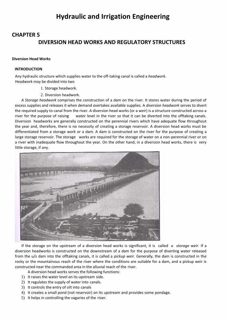
the required supply to canal from the river. A diversion head works (or a weir) is a structure constructed across a river for the purpose of raising water level in the river so that it can be diverted into the offtaking canals.
Diversion headworks are generally constructed on the perennial rivers which have adequate flow throughout the year and, therefore, there is no necessity of creating a storage reservoir. A diversion head works must be
differentiated from a storage work or a dam. A dam is constructed on the river for the purpose of creating a
large storage reservoir. The storage works are required for the storage of water on a non-perennial river or on a river with inadequate flow throughout the year. On the other hand, in a diversion head works, there is very
little storage, if any.
If the storage on the upstream of a diversion head works is significant, it is called a storage weir. If a
diversion headworks is constructed on the downstream of a dam for the purpose of diverting water released from the u/s dam into the offtaking canals, it is called a pickup weir. Generally, the dam is constructed in the
rocky or the mountainous reach of the river where the conditions are suitable for a dam, and a pickup weir is
constructed near the commanded area in the alluvial reach of the river. A diversion head works serves the following functions:
1) It raises the water level on its upstream side. 2) It regulates the supply of water into canals. 3) It controls the entry of silt into canals
4) It creates a small pond (not reservoir) on its upstream and provides some pondage. 5) It helps in controlling the vagaries of the river.
LOCATION OF DIVERSION HEADWORKS The diversion headworks are generally located in the boulder stage or trough stage of the river at a site which
is close to the commanded area of the offtaking canals. If there are a number of sites which are suitable, the final selection is done on the basis of cost. The site which gives the most economical arrangement for the
diversion head works and the distribution works (canals) is usually selected. 1) The river section at the site should be narrow and well-defined.
2) The river should have high, well-defined, inerodible and non-submersible banks so that the cost of river training works is minimum.
3) The canals taking off from the diversion head works should be quite economical and should have a large commanded area.
4) There should be suitable arrangement for the diversion of river during construction. 5) The site should be such that the weir (or barrage) can be aligned at right angles to the direction of flow in
the river.
6) There should be suitable locations for the undersluices, head regulator and other components of the diversion headworks.
7) The diversion headworks should not submerge costly land and property on its upstream. 8) Good foundation should be available at the site. 9) The required materials of construction should be available near the site.
10) The site should be easily accessible by road or rail. 11) The overall cost of the project should be a minimum.
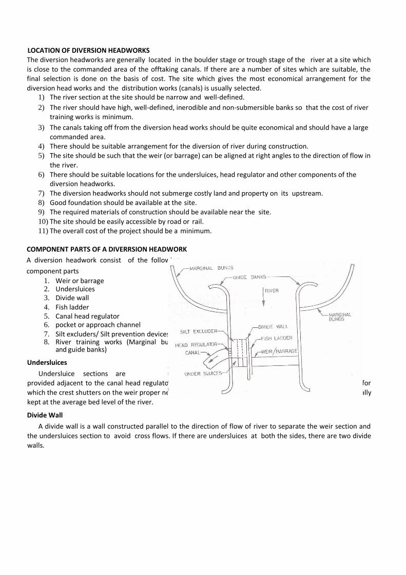
COMPONENT PARTS OF A DIVERRSION HEADWORK
A diversion headwork consist of the following
component parts
1. Weir or barrage 2. Undersluices 3. Divide wall 4. Fish ladder 5. Canal head regulator 6. pocket or approach channel 7. Silt excluders/ Silt prevention devices/ 8. River training works (Marginal bunds
and guide banks)
Undersluices
Undersluice sections are provided adjacent to the canal head regulators. The undersluices should be able to pass fair weather flow for
which the crest shutters on the weir proper need not be dropped. The crest level of the undersluices is generally
kept at the average bed level of the river.
Divide Wall
A divide wall is a wall constructed parallel to the direction of flow of river to separate the weir section and
the undersluices section to avoid cross flows. If there are undersluices at both the sides, there are two divide
walls.
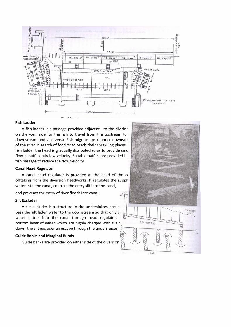
Fish Ladder
A fish ladder is a passage provided adjacent to the divide wall
on the weir side for the fish to travel from the upstream to the
downstream and vice versa. Fish migrate upstream or downstream of the river in search of food or to reach their sprawling places. In a
fish ladder the head is gradually dissipated so as to provide smooth
flow at sufficiently low velocity. Suitable baffles are provided in the fish passage to reduce the flow velocity.
Canal Head Regulator
A canal head regulator is provided at the head of the canal
offtaking from the diversion headworks. It regulates the supply of
water into the canal, controls the entry silt into the canal,
and prevents the entry of river floods into canal.
Silt Excluder
A silt excluder is a structure in the undersluices pocket to
pass the silt laden water to the downstream so that only clear
water enters into the canal through head regulator. The
bottom layer of water which are highly charged with silt pass down the silt excluder an escape through the undersluices.
Guide Banks and Marginal Bunds
Guide banks are provided on either side of the diversion headworks for a smooth
approach and to prevent the river from outflanking. Marginal bunds are provided on either side of the river upstream of diversion headworks to protect the land and property which is likely to be submerged during
ponding of water in floods.
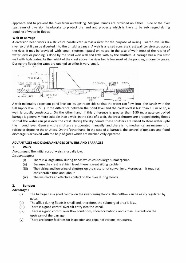
Weir or Barrage A diversion head works is a structure constructed across a river for the purpose of raising water level in the
river so that it can be diverted into the offtaking canals. A weir is a raised concrete crest wall constructed across the river. It may be provided with small shutters (gates) on its top. In the case of weir, most of the raising of
water level or ponding is done by the solid weir wall and little with by the shutters. A barrage has a low crest wall with high gates. As the height of the crest above the river bed is low most of the ponding is done by gates.
During the floods the gates are opened so afflux is very small.
A weir maintains a constant pond level on its upstream side so that the water can flow into the canals with the
full supply level (F.S.L.). If the difference between the pond level and the crest level is less than 1·5 m or so, a
weir is usually constructed. On the other hand, if this difference is greater than 1·50 m, a gate-controlled barrage is generally more suitable than a weir. In the case of a weir, the crest shutters are dropped during floods
so that the water can pass over the crest. During the dry period, these shutters are raised to store water upto the pond level. Generally, the shutters are operated manually, and there is no mechanical arrangement for
raising or dropping the shutters. On the 'other hand, in the case of a barrage, the control of pondage and flood discharge is achieved with the help of gates which are mechanically operated
ADVANTAGES AND DISADVANTAGES OF WEIRS AND BARRAGES
1. Weirs Advantages: The initial cost of weirs is usually low. Disadvantages:
(i) There is a large afflux during floods which causes large submergence.
(ii) Because the crest is at high level, there is great silting problem (iii) The raising and lowering of shutters on the crest is not convenient. Moreover, it requires
considerable time and labour.
(iv) The weir lacks an effective control on the river during floods.
2. Barrages Advantages
(i) The barrage has a good control on the river during floods. The outflow can be easily regulated by
gates. (ii) The afflux during floods is small and, therefore, the submerged area is less. (iii) There is a good control over silt entry into the canal. (iv) There is a good control over flow conditions, shoal formations and cross- currents on the
upstream of the barrage. (v) There are better facilities for inspection and repair of various structures.
(vi) A roadway can be conveniently provided over the structure at a little additional cost.
Disadvantages: The initial cost of the barrage is quite high. Conclusion: A barrage is generally better than a weir. Most of the diversion headworks these days usually consist of barrages.
TYPES OF WEIRS
The weirs may be broadly divided into the following types
(i) Vertical drop weirs.
(ii) Rockfill weirs.
(iii) Concrete glacis or sloping weirs.
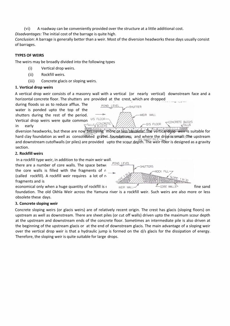
1. Vertical drop weirs
A vertical drop weir consists of a masonry wall with a vertical (or nearly vertical) downstream face and a horizontal concrete floor. The shutters are provided at the crest, which are dropped
during floods so as to reduce afflux. The
water is ponded upto the top of the shutters during the rest of the period.
Vertical drop weirs were quite common in early
diversion headworks, but these are now becoming more or less obsolete. The vertical drop weir is suitable for hard clay foundation as well as consolidated gravel foundations, and where the drop is small. The upstream
and downstream cutofIwalls (or piles) are provided upto the scour depth. The weir floor is designed as a gravity
section.
2. Rockfill weirs
In a rockfill type weir, in addition to the main weir wall,
there are a number of core walls. The space between the core walls is filled with the fragments of rock
(called rockfill). A rockfill weir requires a lot of rock
fragments and is economical only when a huge quantity of rockflll is easily available near the weir site. It is suitable for fine sand foundation. The old Okhla Weir across the Yamuna river is a rockfill weir. Such weirs are also more or less obsolete these days.
3. Concrete sloping weir
Concrete sloping weirs (or glacis weirs) are of relatively recent origin. The crest has glacis (sloping floors) on
upstream as well as downstream. There are sheet piles (or cut off walls) driven upto the maximum scour depth at the upstream and downstream ends of the concrete floor. Sometimes an intermediate pile is also driven at
the beginning of the upstream glacis or at the end of downstream glacis. The main advantage of a sloping weir over the vertical drop weir is that a hydraulic jump is formed on the d/s glacis for the dissipation of energy.
Therefore, the sloping weir is quite suitable for large drops.

Modes of Failure
Irrigation structures (or hydraulic structures) for the diversion and distribution works are weirs, barrages, head
regulators, distributary head regulators, cross regulators, cross-drainage works, etc. These structures are
generally founded on alluvial soils which are highly pervious. Moreover, these soils are easily scoured when
the high velocity water passes over the structures. The failures of weirs constructed on the permeable foundation may occur due to various causes, which may be broadly classified into the following two
categories: 1. Failure due to- subsurface flow 2. Failure due to surface flow
1. Failure due to subsurface flow The failure due to subsurface flow may occur by piping or by rupture of floor due to uplift.
(a) Failure by piping Piping (or undermining) occurs below the weir if the water percolating through the foundation has a large seepage force when it emerges at the downstream end of the impervious floor. When
the seepage force exceeds a certain value, the soil particles are lifted up at the exit point of the seepage. With the removal of the surface soil particles, there is further concentration of flow in the remaining portion and
more soil particles are removed. This process of backward erosion progressively extends towards the upstream
side, and a pipe-like hollow formation occurs beneath the floor. The floor ultimately subsides in the hollows so formed and fails. This type of failure is known as piping failure.
(b) Failure by rupture of floor The water percolating through the foundation exerts an upward pressure on
the impervious floor, called the uplift pressure. If the weight of the floor is not adequate to counterbalance the uplift pressure, it may fail by rupture.
2. Failure due to surface f1ow
The failure due to surface flow may occur by suction pressure due to hydraulic jump or by scouring of the bed.
(a) Failure by suction pressure In the glacis type of weirs, a hydraulic jump is formed on the d/s glacis. In
this case, the water surface profile in the hydraulic jump trough is much lower than the subsoil H.G.L. Therefore
uplift pressure occurs on the glacis. This uplift pressure is known as the suction pressure. If the thickness of floor is not adequate, the rupture of floor may occur.
(b) Failure by scour During floods, scouring occurs in the river bed. The bed of the river may be scoured to a considerable depth. If no suitable measures are adopted, the scour may cause damage to the structure and may lead to the failure.
Design aspects
The basic principles for the design of all irrigation structures on pervious foundations are as follows:
(a) Subsurface flow
1. The structure should be designed such that the piping failure does not occur due to subsurface flow. 2. The downstream pile must be provided to reduce the exit gradient and to prevent piping.
3. An impervious floor of adequate length is provided to increase the path of percolation and to reduce the hydraulic gradient and the seepage force.
4. The seepage path is increased by providing piles and impervious floor to reduce the uplift pressure.
5. The thickness of the floor should be sufficient to resist the uplift pressure due to subsurface flow. The critical section is d/s of the weir/crest wall.
6. A suitably graded inverted filter should be provided at the downstream end of the impervious floor to
check the migration of soil particles along with water. The filter layer is loaded with concrete blocks.
Concrete blocks are also provided at the upstream end.
(b) Surface flow
1. The piles (or cutoff walls) at the upstream and downstream ends of the impervious floor should be
provided upto the maximum scour level to protect the main structure against scour.
2. The launching aprons should be provided at the upstream and downstream ends to provide a cover to
the main structure against scour.
3. A device is required at the downstream to dissipate energy. For large drops, hydraulic jump is used to dissipate the energy.
4. Additional thickness of the impervious floor is provided at the point where the hydraulic jump is formed to counterbalance the suction pressure.
5. The floor is constructed as a monolithic structure to develop bending resistance (or beam action) to
resist the suction pressure. Floor Thickness
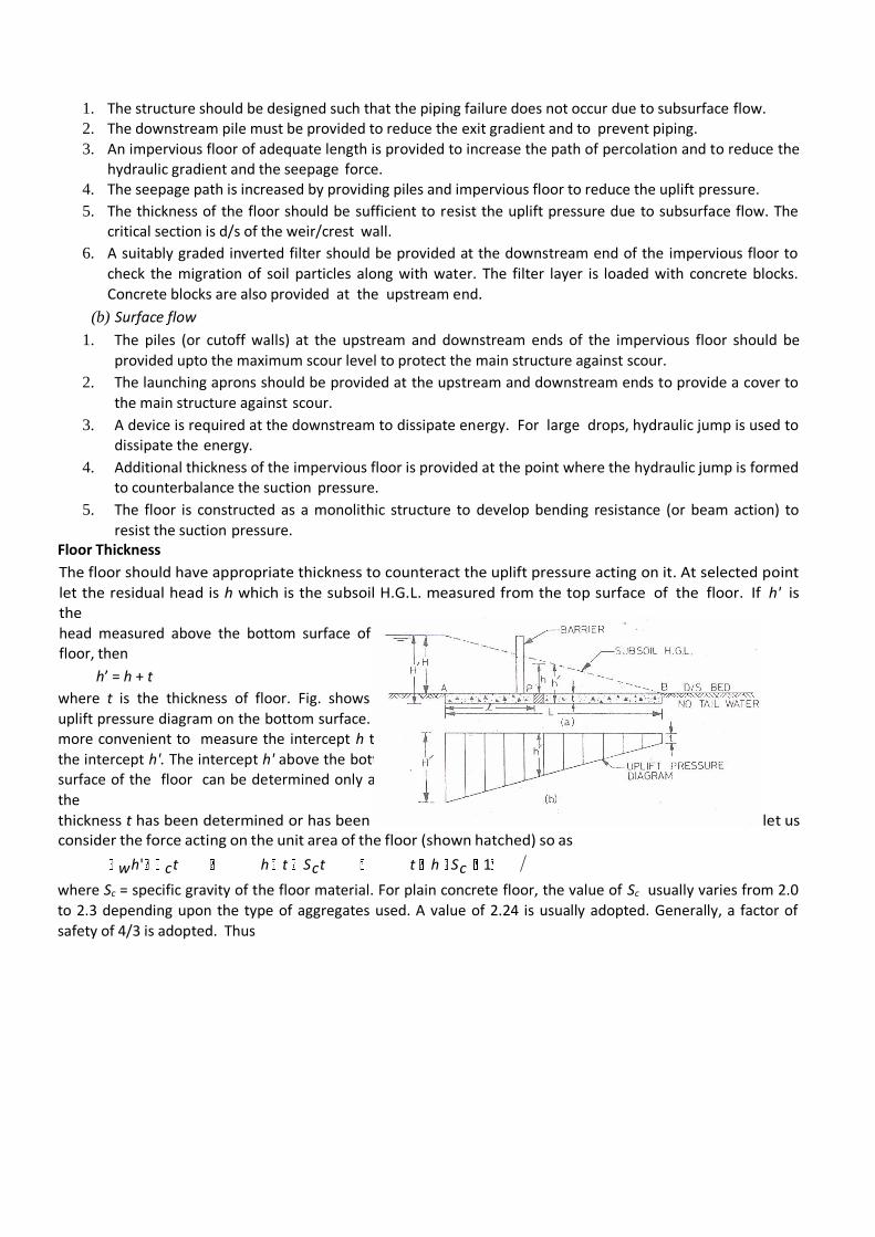
The floor should have appropriate thickness to counteract the uplift pressure acting on it. At selected point
let the residual head is h which is the subsoil H.G.L. measured from the top surface of the floor. If h' is the
head measured above the bottom surface of the floor, then
h’ = h + t
where t is the thickness of floor. Fig. shows the
uplift pressure diagram on the bottom surface. It is more convenient to measure the intercept h than
the intercept h'. The intercept h' above the bottom surface of the floor can be determined only after
the
thickness t has been determined or has been assumed. For the determination of the floor thickness t.let us consider the force acting on the unit area of the floor (shown hatched) so as
wh' ct h t Sct t h Sc 1
where Sc = specific gravity of the floor material. For plain concrete floor, the value of Sc usually varies from 2.0
to 2.3 depending upon the type of aggregates used. A value of 2.24 is usually adopted. Generally, a factor of
safety of 4/3 is adopted. Thus
t 4 h
4 PuH 3 Sc 1 3 Sc 1
where PuH = h is uplift pressure head at that point above the top surface of the floor.
Bligh's Theory
In 1910, W.G. Bligh gave creep theory. According to this theory, the percolating water creeps along the contact
surface of the base profile of the structure with the subsoil. The length of the path thus traversed by the
percolating water is called the length of creep or the creep length. As the water creeps from the upstream end to the downstream end, the head loss occurs. The head loss is proportional to the creep distance travelled.
Bligh made no distinction between the creep in the horizontal direction below the floor and the creep in the vertical direction along the faces of the piles. Bligh's theory is quite simple and convenient. A large number of
early irrigation structures were designed using this theory. Some of these structures are existing even today, but unfortunately a few of them failed. The theory is now rarely used for the design of large, important irrigation
structures. However, sometimes it is used for the design of small structures or for the preliminary design of large
structures. Limitations are: (1) The Bligh theory does not differentiate between the vertical creep and the horizontal creep and gives the same weightage to both, actually, the vertical creep is more effective than the
horizontal creep. (2) The theory assumes that the head loss variation is linear, while the actual head loss variation is non-linear. (3) No distinction is made between the head loss on the outer faces and that on the
inner faces of the sheet piles. Actually, the outer faces are more effective than the inner faces. (4) The theory does not emphasise the importance of the downstream pile without which piping failure occurs. It considers the
downstream pile only as a component of the total creep length and not as a controlling factor for the exit
gradient and the piping. (5) The theory does not give any theoretical or practical method for the determination of the safe gradient. (6) Bligh did not consider the effect of the length of the intermediate pile. Later
investigations by Khosla indicated that the intermediate pile is ineffective if its length is shorter than that of the outer piles. However, there is some local redistribution of uplift pressure.
Further, according to Bligh, the subsoil hydraulic gradient, which is the loss of head per unit length of
creep, is constant throughout the seepage path. Thus if the seepage head (which is the difference of water levels
on the upstream and downstream of weir) is Hs (the total loss of head) and LT is the total creep length, the loss of head per unit length is equal to Hs /LT which is inverse of Bligh’s Creep coefficient C (usually varies from 10
to 18 depending upon the bed material). Therefore for known seepage head and creep coefficient the required creep length or seepage path LT = C Hs. The uplift pressure at any point can be determined by Bligh
theory and then required thickness to counteract it.
Lane's Theory
Lane analysed a large number of dams and weirs founded on pervious foundations which failed or did not fail. He brought out deficiencies in Bligh's creep theory and gave a new theory on statistical basis known as Lane's
weighted creep theory. This theory gives the vertical creep three times more weightage as compared to the
horizontal creep.
Khosla's Theory
In 1926-27, some siphons constructed on the Upper Chenab Canal on the basis of Bligh's creep theory, had
undermining problems. Uplift pressure measurements by Dr. A.N. Khosla, Dr. N.K. Bose and Dr. E.M. Taylor
indicated that the actual uplift pressures were quite different from those computed on the basis of Bligh's theory. These investigations showed that (1) the outer faces of the end sheet piles are much more effective
than the inner faces and the horizontal length of floor, (2) the intermediate piles of smaller in length than the outer
1 1 2
E
piles are ineffective except for some local redistribution of pressure, (3) undermining (piping) of the floors starts from the tail end when the hydraulic gradient at the exit is greater than the critical gradient for that particular
soil. The soil particles move with the flow of water, thus causing progressive degradation of the subsoil and
resulting in cavities below the floor and ultimate failure. Therefore it is absolutely essential to have a reasonably deep cutoff (or pile) at the downstream end of the floor to prevent undermining (or piping).
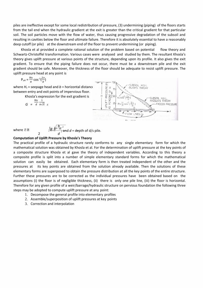
Khosla et al provided a complete rational solution of the problem based on potential flow theory and
Schwartz-Christoffel transformation. Various cases were analysed and studied by them. The resultant Khosla’s theory gives uplift pressure at various points of the structure, depending upon its profile. It also gives the exit
gradient. To ensure that the piping failure does not occur, there must be a downstream pile and the exit gradient should be safe. Moreover, the thickness of the floor should be adequate to resist uplift pressure. The
uplift pressure head at any point is
PuH = Hs
𝜋 cos-1(
2𝑥
𝑏)
where Hs = seepage head and b = horizontal distance
between entry and exit points of impervious floor.
Khosla’s expression for the exit gradient is
G = Hs
𝑑
1
𝜋√𝜆
b where ;
2 d ; and d = depth of d/s pile.
Computation of Uplift Pressure by Khosla’s Theory The practical profile of a hydraulic structure rarely conforms to any single elementary form for which the
mathematical solution was obtained by Khosla et al. For the determination of uplift pressure at the key points of
a composite structure Khosla et al gave the theory of independent variables. According to this theory a composite profile is split into a number of simple elementary standard forms for which the mathematical
solution can easily be obtained. Each elementary form is then treated independent of the other and the pressures at its key points are obtained from the solution already available. Then the solutions of these
elementary forms are superposed to obtain the pressure distribution at all the key points of the entire structure. Further these pressures are to be corrected as the individual pressures have been obtained based on the
assumptions (i) the floor is of negligible thickness, (ii) there is only one pile line, (iii) the floor is horizontal.
Therefore for any given profile of a weir/barrage/hydraulic structure on pervious foundation the following three steps may be adopted to compute uplift pressure at any point:
1. Decompose the general profile into elementary profiles 2. Assemble/superposition of uplift pressures at key points 3. Correction and interpolation
1
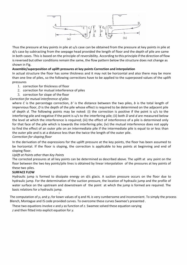
Thus the pressure at key points in pile at u/s case can be obtained from the pressure at key points in pile at
d/s case by subtracting from the seepage head provided the length of floor and the depth of pile are same in both cases. This is based on the principle of reversibility. According to this principle if the direction of flow
is reversed but other conditions remain the same, the flow pattern below the structure does not change as shown in Fig.
Assemble/superposition of uplift pressures at key points Correction and interpolation
In actual structure the floor has some thickness and it may not be horizontal and also there may be more than one line of piles, so the following corrections have to be applied to the superposed values of the uplift
pressures 1. correction for thickness of floor 2. correction for mutual interference of piles 3. correction for slope of the floor
Correction for mutual interference of piles where C is the percentage correction, b' is the distance between the two piles, b is the total length of impervious floor, D is the depth of the pile whose effect is required to be determined on the adjacent pile of depth d. The following points may be noted: (i) the correction is positive if the point is u/s to the interfering pile and negative if the point is u/s to the interfering pile; (ii) both D and d are measured below the level at which the interference is required; (iii) the effect of interference of a pile is determined only for that face of the pile which is towards the interfering pile; (iv) the mutual interference does not apply to find the effect of an outer pile on an intermediate pile if the intermediate pile is equal to or less than the outer pile and is at a distance less than the twice the length of the outer pile. Correction for sloping floor
In the derivation of the expressions for the uplift pressure at the key points, the floor has been assumed to
be horizontal. If the floor is sloping, the correction is applicable to key points at beginning and end of sloping floor. Uplift at Points other than Key Points The corrected pressures at all key points can be determined as described above. The uplift at any point on the floor between the two key points/pile lines is obtained by linear interpolation of the pressures at key points of
these two piles.
SURFACE FLOW Hydraulic jump is formed to dissipate energy on d/s glacis. A suction pressure occurs on the floor due to hydraulic jump. For the determination of the suction pressure, the location of hydraulic jump and the profile of
water surface on the upstream and downstream of the point at which the jump is formed are required. The basic relations for a hydraulic jump.
The computation of y1 and y2 for kown values of q and HL is very cumbersome and inconvenient. To simply the process Blench, Montague and IS code provided curves. To overcome these curves Swamee’s presented .
These two equations involve x and y as function of z. Swamee solved these equation varying z and then fitted into explicit equation for y.
Afflux is the rise in water level on the upstream of the structure after the construction of the weir. The
high flood level on the upstream is higher than that at the downstream. The area of submergence and the top levels of the marginal banks and guide banks depend upon the afflux. The location of the hydraulic jump on
the downstream glacis also depends upon u/s TEL which is a function of afflux. If the afflux is very large, the length of the weir will be small because of high discharge intensity (q) over the crest. However, the cost of the
river training works (guide banks, marginal bunds, etc) will increase. Moreover, the risk of the failure of the structure due to outflanking will also increase. Further, the scour depth will be large and it will increase the cost
of protection works on the upstream and downstream of the impervious floor. The afflux is usually limited to 1
m. IS: 6933-1973 recommends an afflux of 1 m for the alluvial rivers in the upper and middle reaches of the river and of 0,3 m in the lower reaches.
A. hydraulic calculation to fix various levels
B. design for weir wall
C. design for impervious floor and piles 5 points is generally found; depending upon the length of d/s floor. The thickness of floor from the weir wall to d/s end is reduced in steps for ease in construction.
1. Use Khosla’s method to determine uplift pressures and corresponding thicknesses and also exit gradient for tentative dimensions fixed using Bligh’s theory. The final dimensions of the impervious
floor and piles must not be unsafe as well over safe.
B. Design for u/s and d/s protection
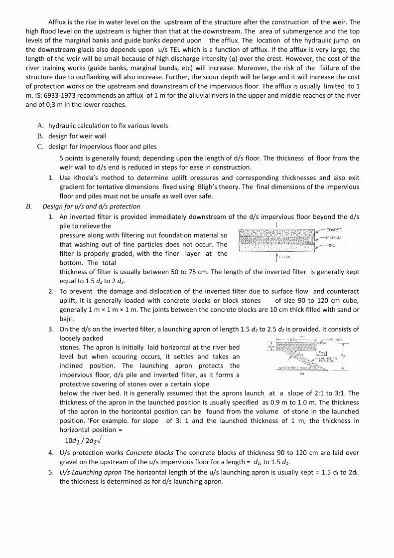
1. An inverted filter is provided immediately downstream of the d/s impervious floor beyond the d/s
pile to relieve the
pressure along with filtering out foundation material so
that washing out of fine particles does not occur. The filter is properly graded, with the finer layer at the
bottom. The total thickness of filter is usually between 50 to 75 cm. The length of the inverted filter is generally kept equal to 1.5 d2 to 2 d2.
2. To prevent the damage and dislocation of the inverted filter due to surface flow and counteract
uplift, it is generally loaded with concrete blocks or block stones of size 90 to 120 cm cube, generally 1 m × 1 m × 1 m. The joints between the concrete blocks are 10 cm thick filled with sand or
bajri.
3. On the d/s on the inverted filter, a launching apron of length 1.5 d2 to 2.5 d2 is provided. It consists of loosely packed stones. The apron is initially laid horizontal at the river bed
level but when scouring occurs, it settles and takes an inclined position. The launching apron protects the
impervious floor, d/s pile and inverted filter, as it forms a
protective covering of stones over a certain slope below the river bed. It is generally assumed that the aprons launch at a slope of 2:1 to 3:1. The
thickness of the apron in the launched position is usually specified as 0.9 m to 1.0 m. The thickness of the apron in the horizontal position can be found from the volume of stone in the launched
position. 'For example. for slope of 3: 1 and the launched thickness of 1 m, the thickness in horizontal position =
10d2 / 2d2 .
4. U/s protection works Concrete blocks The concrete blocks of thickness 90 to 120 cm are laid over
gravel on the upstream of the u/s impervious floor for a length = d1, to 1.5 d1.
5. U/s Launching apron The horizontal length of the u/s launching apron is usually kept = 1.5 dl to 2dl. the thickness is determined as for d/s launching apron.
CHAPTER 6
CROSS DRAINAGE WORKS
INTRODUCTION
When a canal takes ott‘ from a river, it has to cross some streams or rivers before it can reach the top of the intended watershed for the purpose of irrigating an area (as explained in Unit 2). Such crossings constitute various types of cross drainage works that are required to be provided on the canal alignment. Cross drainage works are required to carry the canal by negotiating it above, below or at the same level as the stream across which the canal is meant tta be aligned.
Objectives
By studying this unit you should be able to understand the basic concepts about the following cross drainage works :
an aqueduct,
a syphon aqueduct,
a siphon,
a superpassage,
or inlet and outlet, and
a level crossing.
Further you should be able to
select a suitable type of cross drainage work that is appropriate to given site conditions, and
get an understanding of the various design parameters regarding cross drainage works. NECESSITY OF CROSS DRAINAGE WORKS
canal aligned between the headworks and the main watershed. The canal taking oft from point A on the river has to cross some streams or drainages, a, b, c and d, before it can be taken on the watershed at B. At the intersections or
the canal and the tributaries or streams, ma.l>r cross drainage works will be required.
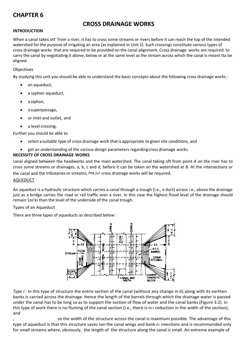
AQUEDUCT
An aqueduct is a hydraulic structure which carries a canal through a trough (i.e., a duct) across i.e., above the drainage just as a bridge carries the road or rail traffic over a river. In this case the highest flood level of the drainage should remain 1oz'ei than the level of the underside of the canal trough.
Types of an Aqueduct
There are three types of aqueducts as described below :
Type I : In this type of structure the entire section of the canal (without any change in it) along with its earthen banks is carried across the drainage. Hence the length of the barrels through which the drainage water is passed under the canal has to be long so as to support the section of flow of water and the canal banks (Figure 3.2). In this type of work there is no fluming of the canal section (i.e., there is n‹› reduction in the width of the section), and , so the width of the structure across the canal is maximum possible. The advantage of this type of aqueduct is that this structure saves tan the canal wings and bank c‹ nnections and is recommended only for small streams where, obviously, the length of the structure along the canal is small. An extreme example of
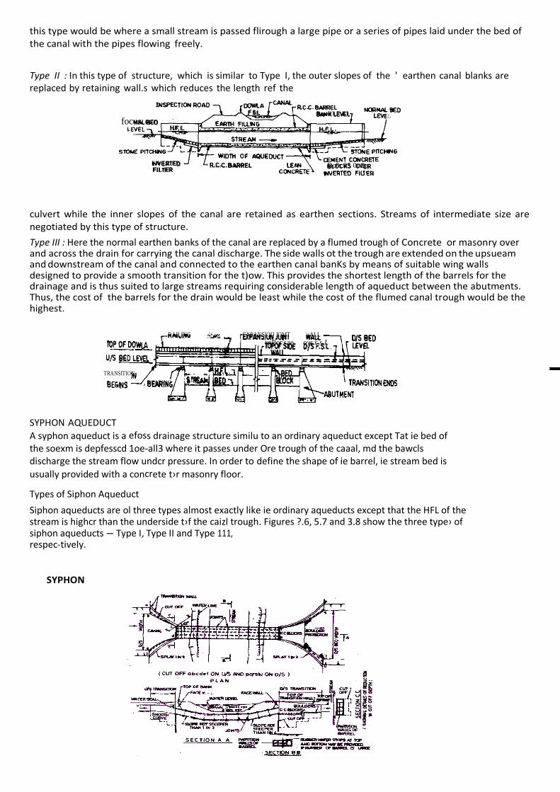
this type would be where a small stream is passed flirough a large pipe or a series of pipes laid under the bed of the canal with the pipes flowing freely.
Type II : In this type of structure, which is similar to Type I, the outer slopes of the ' earthen canal blanks are replaced by retaining wall.s which reduces the length ref the
culvert while the inner slopes of the canal are retained as earthen sections. Streams of intermediate size are negotiated by this type of structure.
Type III : Here the normal earthen banks of the canal are replaced by a flumed trough of Concrete or masonry over and across the drain for carrying the canal discharge. The side walls ot the trough are extended on the upsueam and downstream of the canal and connected to the earthen canal banKs by means of suitable wing walls designed to provide a smooth transition for the t)ow. This provides the shortest length of the barrels for the drainage and is thus suited to large streams requiring considerable length of aqueduct between the abutments. Thus, the cost of the barrels for the drain would be least while the cost of the flumed canal trough would be the highest.
SYPHON AQUEDUCT
A syphon aqueduct is a efoss drainage structure similu to an ordinary aqueduct except Tat ie bed of the soexm is depfesscd 1oe-all3 where it passes under Ore trough of the caaal, md the bawcls discharge the stream flow undcr pressure. In order to define the shape of ie barrel, ie stream bed is
usually provided with a concrete t›r masonry floor.
Types of Siphon Aqueduct
Siphon aqueducts are ol three types almost exactly like ie ordinary aqueducts except that the HFL of the stream is highcr than the underside t›f the caizl trough. Figures ?.6, 5.7 and 3.8 show the three type› of siphon aqueducts — Type I, Type II and Type 111, respec-tively. SYPHON
SL Bzw¥ LE\EL
focus. eco LEVEL
HF. L -
¥JVERtED FlLtER
R.C.C. BARREt. 1.E Bc0c85 0u£p
RAILING -’• EXPANSlOfJ JOMT \sALL
roPor sae oys r.s.L
TRANSITION
BEARING ' docx
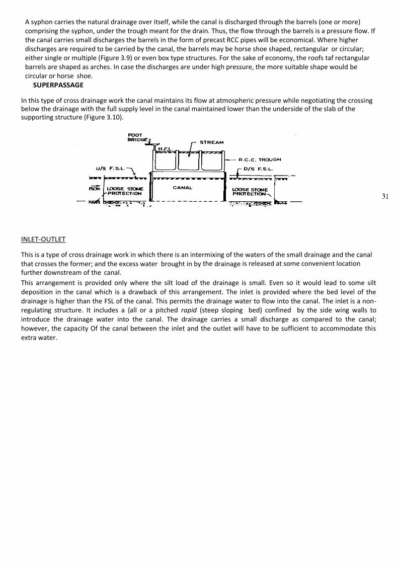
A syphon carries the natural drainage over itself, while the canal is discharged through the barrels (one or more) comprising the syphon, under the trough meant for the drain. Thus, the flow through the barrels is a pressure flow. If the canal carries small discharges the barrels in the form of precast RCC pipes will be economical. Where higher discharges are required to be carried by the canal, the barrels may be horse shoe shaped, rectangular or circular; either single or multiple (Figure 3.9) or even box type structures. For the sake of economy, the roofs taf rectangular barrels are shaped as arches. In case the discharges are under high pressure, the more suitable shape would be circular or horse shoe. SUPERPASSAGE
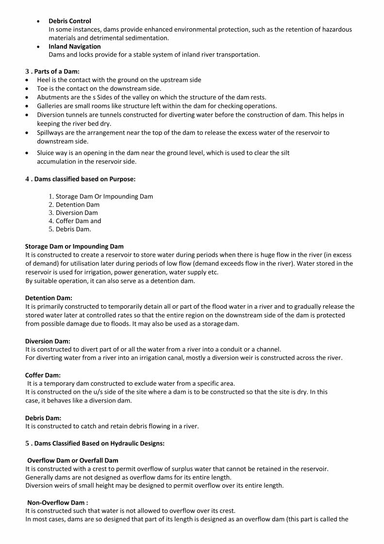
In this type of cross drainage work the canal maintains its flow at atmospheric pressure while negotiating the crossing below the drainage with the full supply level in the canal maintained lower than the underside of the slab of the supporting structure (Figure 3.10).
INLET-OUTLET
This is a type of cross drainage work in which there is an intermixing of the waters of the small drainage and the canal that crosses the former; and the excess water brought in by the drainage is released at some convenient location further downstream of the canal.
This arrangement is provided only where the silt load of the drainage is small. Even so it would lead to some silt deposition in the canal which is a drawback of this arrangement. The inlet is provided where the bed level of the drainage is higher than the FSL of the canal. This permits the drainage water to flow into the canal. The inlet is a non-regulating structure. It includes a {all or a pitched rapid (steep sloping bed) confined by the side wing walls to introduce the drainage water into the canal. The drainage carries a small discharge as compared to the canal; however, the capacity Of the canal between the inlet and the outlet will have to be sufficient to accommodate this extra water.

CHAPTER 7
DAMS
1. Introduction:
A dam is a barrier or large impounding structure designed and constructed on a water course to confine large volume of water and then control the flow of water. It will retain water at the upstream side of the structure. A reservoir is the water retained by such a huge structure. A dam is an artificially created barrier that impounds surface water derived from a small or a large catchment. It may be also a subsurface dam to store underground water. The mass of water stored at upstream side of the dam is called as reservoir. Reservoirs created by dams not only controls floods but also provide water for several human activities . They are irrigation, human consumption, industrial use, aquaculture, recreation, power generation, and navigability. Hydropower is often used in conjunction with dams to generate electricity. A dam can also be used to collect and store water which can be evenly distributed between locations, through
canals or pipelines. Dams generally serve the primary purpose of retaining water, while other structures such as floodgates or levees (also known as dikes) are used to manage or prevent water flow into specific land regions.
2. Benefits provided by dams
Benefits provided by dams include water supplies for drinking, irrigation and industrial uses; flood control; recreation; and navigation. At the same time, dams also represent a risk to public safety.
Man-made dams are typically classified according to their size (height), intended purpose or structures.
Dams provide a wide range of economic, environmental, and social benefits. The following are the major benefits:
Water Storage (Fire & Farm Ponds) Dams create reservoirs that supply water for many uses, including industrial, municipal, and agricultural.
Irrigation A major part of dam water is used for irrigation. Most of the cropland is irrigated using water stored behind dams.
Electrical Generation Hydropower is considered to be clean source form dams because it does not contribute to global warming, air pollution, acid rain, or ozone depletion.
Recreation is one of the benefits Dams provide prime recreational facilities like Boating, skiing, camping, picnic areas, and boat launch facilities.
Flood Control In addition to helping farmers, dams help prevent the loss of life and property caused by flooding. Flood control dams impound floodwaters and then either release them under control to the river below the dam or store or divert the water for other uses.
Debris Control In some instances, dams provide enhanced environmental protection, such as the retention of hazardous materials and detrimental sedimentation.
Inland Navigation Dams and locks provide for a stable system of inland river transportation.
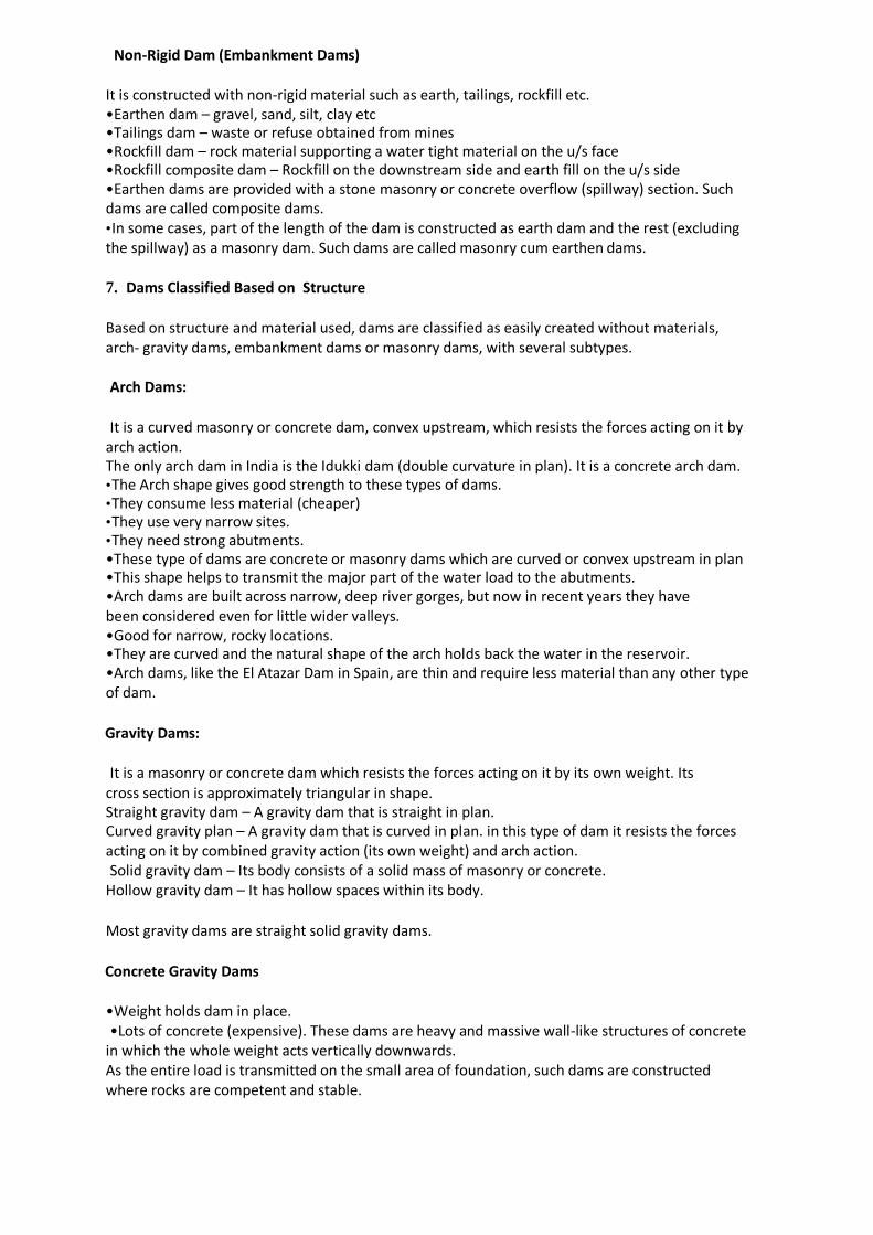
3 . Parts of a Dam: Heel is the contact with the ground on the upstream side Toe is the contact on the downstream side. Abutments are the s Sides of the valley on which the structure of the dam rests. Galleries are small rooms like structure left within the dam for checking operations. Diversion tunnels are tunnels constructed for diverting water before the construction of dam. This helps in
keeping the river bed dry.
Spillways are the arrangement near the top of the dam to release the excess water of the reservoir to downstream side.
Sluice way is an opening in the dam near the ground level, which is used to clear the silt accumulation in the reservoir side.
4 . Dams classified based on Purpose:
1. Storage Dam Or Impounding Dam 2. Detention Dam 3. Diversion Dam 4. Coffer Dam and 5. Debris Dam.
Storage Dam or Impounding Dam It is constructed to create a reservoir to store water during periods when there is huge flow in the river (in excess of demand) for utilisation later during periods of low flow (demand exceeds flow in the river). Water stored in the reservoir is used for irrigation, power generation, water supply etc. By suitable operation, it can also serve as a detention dam.
Detention Dam: It is primarily constructed to temporarily detain all or part of the flood water in a river and to gradually release the stored water later at controlled rates so that the entire region on the downstream side of the dam is protected from possible damage due to floods. It may also be used as a storage dam.
Diversion Dam: It is constructed to divert part of or all the water from a river into a conduit or a channel. For diverting water from a river into an irrigation canal, mostly a diversion weir is constructed across the river.
Coffer Dam: It is a temporary dam constructed to exclude water from a specific area.
It is constructed on the u/s side of the site where a dam is to be constructed so that the site is dry. In this case, it behaves like a diversion dam.
Debris Dam: It is constructed to catch and retain debris flowing in a river.
5 . Dams Classified Based on Hydraulic Designs:
Overflow Dam or Overfall Dam
It is constructed with a crest to permit overflow of surplus water that cannot be retained in the reservoir. Generally dams are not designed as overflow dams for its entire length. Diversion weirs of small height may be designed to permit overflow over its entire length.
Non-Overflow Dam :
It is constructed such that water is not allowed to overflow over its crest. In most cases, dams are so designed that part of its length is designed as an overflow dam (this part is called the

spillway) while the rest of its length is designed as a non-overflow dam. In some cases, these two sections are not combined.
6. Dams Classified Based on Material of Construction Rigid Dam: It is constructed with rigid material such as stone, masonry, concrete, steel, or timber. Steel dams (steel plates supported on inclined struts) and timber dams (wooden planks supported on a wooden framework) are constructed only for small heights (rarely).
Non-Rigid Dam (Embankment Dams)
It is constructed with non-rigid material such as earth, tailings, rockfill etc. •Earthen dam – gravel, sand, silt, clay etc •Tailings dam – waste or refuse obtained from mines •Rockfill dam – rock material supporting a water tight material on the u/s face •Rockfill composite dam – Rockfill on the downstream side and earth fill on the u/s side •Earthen dams are provided with a stone masonry or concrete overflow (spillway) section. Such dams are called composite dams. • In some cases, part of the length of the dam is constructed as earth dam and the rest (excluding the spillway) as a masonry dam. Such dams are called masonry cum earthen dams.
7. Dams Classified Based on Structure
Based on structure and material used, dams are classified as easily created without materials, arch- gravity dams, embankment dams or masonry dams, with several subtypes.
Arch Dams:
It is a curved masonry or concrete dam, convex upstream, which resists the forces acting on it by
arch action. The only arch dam in India is the Idukki dam (double curvature in plan). It is a concrete arch dam. • The Arch shape gives good strength to these types of dams. • They consume less material (cheaper) • They use very narrow sites. • They need strong abutments. •These type of dams are concrete or masonry dams which are curved or convex upstream in plan •This shape helps to transmit the major part of the water load to the abutments. •Arch dams are built across narrow, deep river gorges, but now in recent years they have been considered even for little wider valleys. •Good for narrow, rocky locations. •They are curved and the natural shape of the arch holds back the water in the reservoir. •Arch dams, like the El Atazar Dam in Spain, are thin and require less material than any other type of dam.
Gravity Dams:
It is a masonry or concrete dam which resists the forces acting on it by its own weight. Its cross section is approximately triangular in shape. Straight gravity dam – A gravity dam that is straight in plan. Curved gravity plan – A gravity dam that is curved in plan. in this type of dam it resists the forces acting on it by combined gravity action (its own weight) and arch action. Solid gravity dam – Its body consists of a solid mass of masonry or concrete.
Hollow gravity dam – It has hollow spaces within its body.
Most gravity dams are straight solid gravity dams.
Concrete Gravity Dams
•Weight holds dam in place. •Lots of concrete (expensive). These dams are heavy and massive wall-like structures of concrete
in which the whole weight acts vertically downwards. As the entire load is transmitted on the small area of foundation, such dams are constructed where rocks are competent and stable.
•Bhakra Dam is the highest Concrete Gravity dam in Asia and the second highest in the world. •Bhakra Dam is across river Sutlej in Himachal Pradesh. •The construction of this project was started in the year 1948 and was completed in 1963 . • It is 740 ft. high above the deepest foundation as straight concrete dam being more than three times the height of Qutab Minar. •Length at top 518.16m (1700 feet); width at base 190.5m (625 feet), and at the top is 9.14m (30 feet) •Bhakra Dam is the highest Concrete Gravity dam in Asia and Second Highest in the world.
Arch-gravity dams:
These are of mixed composition of both gravity and arch dams.
Buttress Dam:
It consists of water retaining sloping membrane or deck on the u/s which is supported by a series of buttresses. These buttresses are in the form of equally spaced triangular masonry or reinforced concrete walls or counterforts. The sloping membrane is usually a reinforced concrete slab. In some cases, the u/s slab is replaced by multiple arches supported on buttresses (multiple arch buttress dam) or by flaring the u/s edge of the buttresses to span the distance between the buttresses (bulkhead buttress dam or massive head buttress dam). In general, the structural behaviour of a buttress dam is similar to that of a gravity dam.
1. Face is held up by a series of supports. 2. Flat or curved face. 3. Buttress Dam – Is a gravity dam reinforced by structural supports. 4. Buttress – a support that transmits a force from a roof or wall to another supporting structure. 5. This type of structure can be considered even if the foundation rocks are little weaker.
Barrages:
A barrage dam is a special kind of dam which consists of a line of large gates that can be opened
or closed to control the amount of water passing the dam. The gates are set between flanking piers which are responsible for supporting the water load, and are often used to control and stabilize water flow for irrigation systems. Barrages that are built at the mouths of rivers or lagoons to prevent tidal incursions or utilize the
tidal flow for tidal power are known as tidal barrages.
Embankment dams :
These are Earth Dams. They are trapezoidal in shape. Earth dams are constructed where the foundation or the underlying material or rocks are weak to support the masonry dam or where the suitable competent rocks are at greater depth. •Earthen dams are relatively smaller in height and broad at the base. They are mainly built with clay, sand and gravel, hence they are also known as Earth fill dam or Rock fill dam. Embankment dams are also armed with a dense, waterproof core that prevents water from seeping through the structure. It is a non-rigid dam which resists the forces acting on it by its shear strength and to some extent
also by its own weight (gravity). Its structural behaviour is in many ways different from that of a gravity dam.
8. Dams are classified based on material:
The dams are classified based on material include:

1. Steel dams and 2. Timber dams.
The miscellaneous types of Dams include a) Natural dams b) Beaver dams.
There are many ways in which natural lakes and their dams can form in nature. Natural dams have many economic benefits, including hydropower generation and recreation, but also can constitute serious hazards. In the last one hundred years, a number of catastrophic events associated with rockslide dam formation and failure have occurred in the mountain regions of the world. Most of them happened in the natural dams only. Natural dams may cause upstream flooding as the lake rises and downstream flooding as a result of failure of the dam.
Beaver dams are dams built by beavers to provide ponds as protection against predators such as coyotes, wolves, and bears, and to provide easy access to food during winter. Beavers and their dams play an important role in nature. Because of the dramatic effects their dams have on surrounding ecosystems, these mammals are considered a keystone species.
By constructing dams they create wetlands -- lush environments which attract fish, ducks, frogs and other creatures. Beaver dams are common in forested areas of western Canada. Beavers construct dams of sticks and mud. Breaches in the dams are continuously repaired by the beaver while local food supplies (the inner bark of deciduous trees) last - usually six to ten years.
There is also a technical classification of dams. It is based on three factors.
Class of Dam Maximum Depth of
Water at NWL (m) Impoundment at NWL (m3)
Catchment Area (km2)
A (Low Hazard) 0 - 4.99 <100,000 <100
B (Medium Hazard) 5.00 - 14.99 100,000 to 1,000,000 100 to 1,000
C (High Hazard) >15.00 >1,000,000 >1,000
NWL = Normal Water Level
When using the table above, it is important to note that only one factor is necessary to place a dam into a higher hazard class. For example, a 3m deep reservoir with 20,000 cubic meters of storage and a 1,500 square kilometre catchment area would classify as a high hazard dam due to its large catchment area. Similarly, a 15.5m tall mass gravity wall with 25,000 cubic meters of storage and a 3 square kilometre catchment area would be a high hazard dam due to the maximum water depth.
9 . Causes of Dam Failure:
This itself is a different topic. Dam failures are of particular concern because the failure of a large dam has the potential to cause more death and destruction than the failure of any other man-made structure.
This is because of the destructive power of the flood wave that would be released by the sudden collapse of a large dam. In general, a failure results in the release of large quantities of water, posing serious risks for the people or property downstream. Failure of earth dams may
be: 1.Hydraulic Failure 2. Seepage Failure 3.Structural Failure
The following are some of the reasons for dam failure: 1. Overtopping of embankment dams due to inadequate spillway discharge capacity to pass flood
waters. 2. Faults in construction methods (eg inadequate compaction of fill) or use of the wrong type of
construction materials.
3. Geological problems with the dam foundation. 4. Landslides which fall into the storage reservoir 5. Earthquakes can certainly cause damage to dams.
1. The causes of Hydraulic Failure includes these factors:
1.Overtopping of dams. 2.Erosion of the Upstream Surface 3.Erosion of the Downstream Surface 4.Erosion of the Downstream toe.
2. Seepage Failure: 3. Structural Failure: Slip failure in Dams - Structural failure . Failure due to sliding of foundation. 4. Damage due to burrowing animals 5. Failure of dam due to earthquake or neotectonic movements.
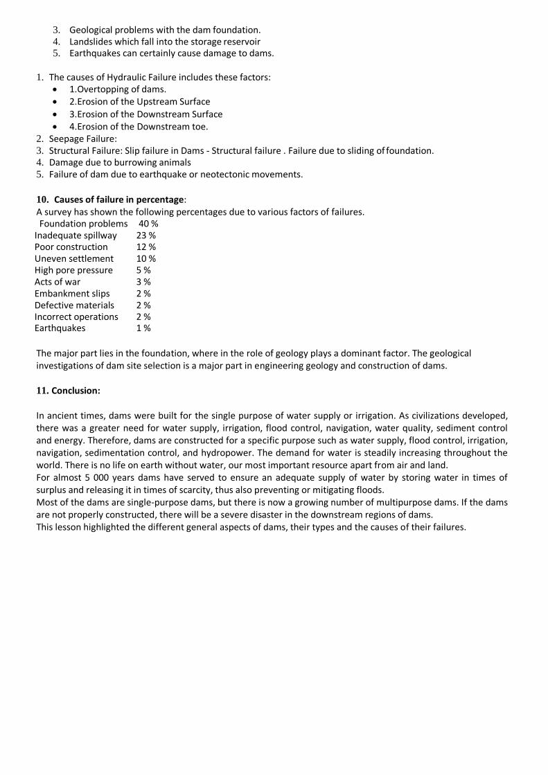
10. Causes of failure in percentage: A survey has shown the following percentages due to various factors of failures. Foundation problems 40 %
Inadequate spillway 23 % Poor construction 12 % Uneven settlement 10 % High pore pressure 5 % Acts of war 3 % Embankment slips 2 % Defective materials 2 % Incorrect operations 2 % Earthquakes 1 %
The major part lies in the foundation, where in the role of geology plays a dominant factor. The geological investigations of dam site selection is a major part in engineering geology and construction of dams.
11. Conclusion:
In ancient times, dams were built for the single purpose of water supply or irrigation. As civilizations developed, there was a greater need for water supply, irrigation, flood control, navigation, water quality, sediment control and energy. Therefore, dams are constructed for a specific purpose such as water supply, flood control, irrigation, navigation, sedimentation control, and hydropower. The demand for water is steadily increasing throughout the world. There is no life on earth without water, our most important resource apart from air and land. For almost 5 000 years dams have served to ensure an adequate supply of water by storing water in times of surplus and releasing it in times of scarcity, thus also preventing or mitigating floods. Most of the dams are single-purpose dams, but there is now a growing number of multipurpose dams. If the dams are not properly constructed, there will be a severe disaster in the downstream regions of dams. This lesson highlighted the different general aspects of dams, their types and the causes of their failures.