SPINNER SPREADER - Gearmore · SPINNER SPREADER Operation, Service & Parts Manual For Models S203L,...
19
SPINNER SPREADER Operation, Service & Parts Manual For Models S203L, S273L & S503L May 2006 Form: Spnsprdr.PM65
Transcript of SPINNER SPREADER - Gearmore · SPINNER SPREADER Operation, Service & Parts Manual For Models S203L,...

SPINNER
SPREADER
Operation, Service &Parts ManualFor Models
S203L, S273L& S503L
May 2006
Form: Spnsprdr.PM65

TABLE OF CONTENTS
Welcome/Introduction ..................................................................................... 1Training .................................................................................................. 1Pre-Operation ....................................................................................... 1
Spreader Assembly .........................................................................................2-3General Maintenance ........................................................................................ 4
Lubrication ............................................................................................ 4Cleaning & Storage .............................................................................. 4Safety Information ............................................................................... 4
Safety Instructions ............................................................................................. 5Operation Safety ................................................................................... 5
To Operate Spreader ......................................................................................... 6Spreading Tables .............................................................................................7-9Frame Assembly S203L .................................................................................. 10Frame Assembly S273L/S503L .................................................................... 11Spreading Disc Assembly ............................................................................... 12Lever Controls ................................................................................................. 13Optional Agitator Assembly .......................................................................... 14Gearbox Assembly .......................................................................................... 15Driveline Assembly ......................................................................................... 16Limited Warranty ............................................................................................. 17
DATE OF PURCHASE: ______________________
MODEL NUMBER: _________________________
SERIAL NUMBER: _________________________

WELCOME / INTRODUCTION
1
We would like to thank you for purchasing a Gearmore product and we assureyou that you have made a good choice, as now you have a very high qualitymachine. Please follow all instructions contained in this manual for a long andtrustworthy machine life.
TRAINING -
Know your controls. Read this operator's manual and the manual provided with your tractor.
Learn how to stop the tractor engine and spreader quickly in case of an emergency.
DO NOT allow adults without proper instructions or children to operate machinery.
BEFORE OPERATING THE SPREADER -
Before operating the spreader please do the following:
- Inspect for damage and loose or missing parts.
- Make sure all fittings and drive components are secure.
- Lubrication - See Lubrication Section.
- Check hopper for any foreign objects.

SPREADER ASSEMBLY
2
Fig. 1 - Bolt the gearbox to the frame.
Fig. 2 - Partially install pin into disc be-fore assembling to gearbox shaft. Insertthe spinner disc onto the driven outputshaft, and align holes and drive in the rollpin "a", which is lower hole. Drive rollpin in until flush with bushing.
Fig. 3 - Insert the roll pins into hole "b".Drive in the pins until the distance is equalon both sides of the shaft.
Fig. 4 - Put control lever rods, for meteringgates to the inside of the frame before placinghopper onto the frame.
SPREADER ASSEMBLY
3
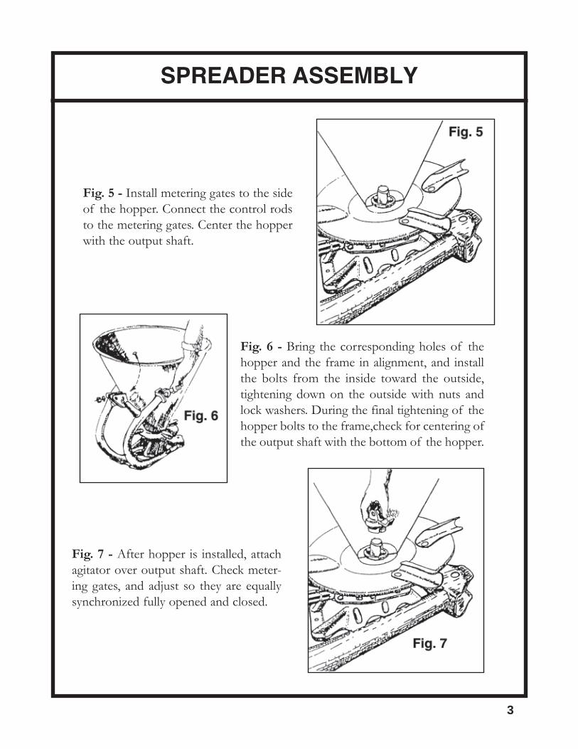
Fig. 5 - Install metering gates to the sideof the hopper. Connect the control rodsto the metering gates. Center the hopperwith the output shaft.
Fig. 6 - Bring the corresponding holes of thehopper and the frame in alignment, and installthe bolts from the inside toward the outside,tightening down on the outside with nuts andlock washers. During the final tightening of thehopper bolts to the frame,check for centering ofthe output shaft with the bottom of the hopper.
Fig. 7 - After hopper is installed, attachagitator over output shaft. Check meter-ing gates, and adjust so they are equallysynchronized fully opened and closed.

MAINTENANCE
4
LUBRICATION -
DRIVESHAFT - The driveshaft must be lubricated before the spreader is put into use. After that,grease every 8 hours. It is also necessary, from time to time, to untelescope the driveshaft to cleanand re-grease tubings.
GEARBOX - Grease every 40 hours.
CLEANING AND STORAGE -
- Wash hopper with water after each use.
- Never let material buildup on shutters or in the hopper.
- Check spreader for needed repairs before using again.
SAFETY INFORMATION -
Safety Tips:
1. Always wear relatively tight and belted clothing when operating spreader.Loose clothing should not be worn, as it could get caught in the moving partsor controls of spreader.
2. Spreader should be operated only by qualified personnel.
3. When starting spreader, always maintain a safe distance from moving parts.
4. Keep hands, feet, and clothing away from all moving parts.

SAFETY INFORMATION
5
OPERATIONAL SAFETY
It is absolutely necessary to empty the hopper before lowering the spreader to theground.
Guards and safety shields are for your protection. DO NOT operate equipmentunless they are in place.
ALWAYS engage tractor PTO at engine idle.
Disengage tractor PTO and shift into neutral before attempting to start engine.
Read and observe all safety decals on the tractor and spreader.
NEVER allow anyone, other than the operator, within 25' of machine while inoperation.
DO NOT stop or start suddenly when going uphill or downhill. Avoid operationon steep slopes.
Be alert for holes in terrain and other hidden hazards. ALWAYS drive slowly overrough ground.
Reduce speed on slopes and in sharp turns to prevent tipping or loss of control. BEcareful when changing directions on slopes.
Take all possible precautions when leaving tractor unattended: Disengage PTO,lower spreader, shift into neutral, set parking brake, stop engine, and remove keyfrom ignition.
Front tractor weights or front tire ballast should be used to enhance front-end sta-bility on small tractors.

TO OPERATE SPREADER
6
NEVER put hands or hand held tools in spreader while PTO is engagedand gearbox is turning. Failure to follow warning can result in personalinjury and/or damage to the spreader.
A) Make sure spreader is properly assembled and secure to 3-point hitch.
B) Before using spreader, make sure that the spreading disc is in a horizontalposition, about 2 1/2 feet from the ground.
C) Engage tractor PTO at engine idle.
NOTE: Never engage PTO above engine idle.
D) Place material to be spread in hopper.
E) Set levers in position needed for your spreading application (See page 5for tables).
WARNING
SPREADING TABLES
7
The figures shown in the table, in particular the spreading quantities, have been establishedthrough appropriate practical testing. The figures are only general indications, because a lotof external elements can modify the spreading (the wind, the moisture of fertilizer, etc.).
If the tractor is driven at a speed which differs from that shown from the table, it is neces-sary to make the right proportions and you must remember that a constant opening and agreater forward speed with constant PTO regime, reduces the quantity of spread for hectar.
THE SPREADING OPERATION
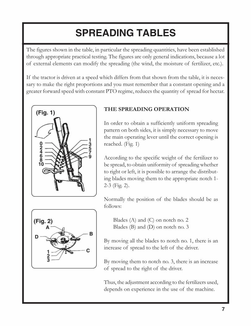
In order to obtain a sufficiently uniform spreadingpattern on both sides, it is simply necessary to movethe main operating lever until the correct opening isreached. (Fig. 1)
According to the specific weight of the fertilizer tobe spread, to obtain uniformity of spreading whetherto right or left, it is possible to arrange the distribut-ing blades moving them to the appropriate notch 1-2-3 (Fig. 2).
Normally the position of the blades should be asfollows:
Blades (A) and (C) on notch no. 2Blades (B) and (D) on notch no. 3
By moving all the blades to notch no. 1, there is anincrease of spread to the left of the driver.
By moving them to notch no. 3, there is an increaseof spread to the right of the driver.
Thus, the adjustment according to the fertilizers used,depends on experience in the use of the machine.

MagnesiumMari
FeedSet
2.48 3.72 4.97 6.2 7.4 8.7
M.P.H.
2 392 261 196 156 130 111
34
13092765
8731843
6541383
5231105
435920
373789
Spreading applicationquantity in LBS/ACRE
P.T.O.: 540 min.
56
37535854
25003902
18762927
15012343
12501950
1071167113.12 foot
Quick Lime FeedSet
2.48 3.72 4.97 6.2 7.4 8.7
M.P.H.
2 251 167 125 100 83 71
34
8402119
5601413
4201059
335847
280705
239604
Spreading applicationquantity in LBS/ACRE
P.T.O.: 540 min.
56
35135937
23423958
17568968
14052374
11701978
10021694
78
73098263
48735514
36544131
29233305
24342753
20862359
SPREADING TABLES
8
13.12 foot
AmmoniumNitrate
FeedSet
2.48 3.72 4.97 6.2 7.4 8.7
M.P.H.
34
186442
124295
92221
73176
61146
-126
Spreading applicationquantity in LBS/ACRE
P.T.O.: 540 min.
56
639966
426544
319483
255386
212321
182275
7 1190 793 595 476 396 339
23 foot
Rhe-Ka-Phos FeedSet
2.48 3.72 4.97 6.2 7.4 8.7
M.P.H.
34
248492
165328
124245
99197
82163
70140
Spreading applicationquantity in LBS/ACRE
P.T.O.: 540 min.
56
8191270
546846
409634
327507
272423
233326
715211726
10141151
760863
608690
506575
433-
910
17521944
11681296
875972
700777
583647
--
26.2 foot
Thomas Slag(Phosphate)
FeedSet
2.48 3.72 4.97 6.2 7.4 8.7
M.P.H.
2 260 173 129 103 85 73
34
8721803
5811202
435901
348720
289600
248514
Spreading applicationquantity in LBS/ACRE
P.T.O.: 540 min.
56
2478 1652 1239 990 825 70813.12 foot
AmmoniumSulphate
FeedSet
2.48 3.72 4.97 6.2 7.4 8.7
M.P.H.
34
342751
228501
191375
136300
113250
97214
Spreading applicationquantity in LBS/ACRE
P.T.O.: 540 min.
56
10321532
6881021
515766
413613
343510
294437
7 1806 1204 902 721 601 514
26.2 foot
(Granular)Potassium
FeedSet
2.48 3.72 4.97 6.2 7.4 8.7
M.P.H.
2 111 74 55 44 37 -
34
373816
249543
186407
149325
124271
106232
Spreading applicationquantity in LBS/ACRE
P.T.O.: 540 min.
56
11971795
7981197
599897
478718
398597
34151213.12 foot
ThomasPotassium
(Grains)
FeedSet
2.48 3.72 4.97 6.2 7.4 8.7
M.P.H.
34
272664
182442
136332
109265
91220
77188
Spreading applicationquantity in LBS/ACRE
P.T.O.: 540 min.
56
9771496
651998
488748
390598
325498
299423
78
18122072
12081381
9061036
724829
604690
517591
910
20932322
13961548
10461161
837928
697773
597662
26.2 foot

GrainedPotassium
FeedSet
2.48 3.72 4.97 6.2 7.4 8.7
M.P.H.
34
154378
103253
77189
62151
51126
-108
Spreading applicationquantity in LBS/ACRE
P.T.O.: 540 min.
56
591918
394612
295459
235367
196305
168262
78
10961218
730812
548609
438486
364406
312347
910
12371415
825944
618707
494566
411471
352404
SPREADING TABLES
9
32.8 foot
29.5 foot
Superphosphate FeedSet
2.48 3.72 4.97 6.2 7.4 8.7
M.P.H.
2 46 31 23 - - -
34
160410
107273
80205
64163
53136
-117
Spreading applicationquantity in LBS/ACRE
P.T.O.: 540 min.
56
627959
418639
313479
251383
208319
179273
78
11101223
740815
555611
443488
369406
316349
910
12551444
837963
627721
502577
417480
358412
32.8 foot
Ammoniumand Calcium
Nitrate
FeedSet
2.48 3.72 4.97 6.2 7.4 8.7
M.P.H.
34
137327
91218
68163
-130
-108
-93
Spreading applicationquantity in LBS/ACRE
P.T.O.: 540 min.
56
494783
329522
246391
197313
163260
140223
78
9551082
637721
478540
381432
317360
272308
910
10891242
726828
544621
435496
362413
310354
29.5 foot
N.P.K. Types FeedSet
2.48 3.72 4.97 6.2 7.4 8.7
M.P.H.
34
130345
87230
64172
52137
-115
-98
Spreading applicationquantity in LBS/ACRE
P.T.O.: 540 min.
56
537842
358561
268421
214336
178280
153240
78
10281164
685976
513582
411465
342387
293332
910
11851350
790900
592675
473540
394440
338385
31.8 foot
CoarseGrained
Potassium
FeedSet
2.48 3.72 4.97 6.2 7.4 8.7
M.P.H.
34
135360
91240
67180
54144
-119
-102
Spreading applicationquantity in LBS/ACRE
P.T.O.: 540 min.
56
550862
367575
275431
219344
182287
156245
78
10691232
712821
534515
427492
355410
305351
910
12501402
833935
624701
499580
415467
356400

S203L FRAME ASSEMBLY
10
REF # QTY. PART NO. DESCRIPTION
1 1 C016019 Hopper2 1 T003049 Frame3 2 D001002 Nut M104 4 V003016 Bolt M10 x 205 2 R004002 Washer6 4 D001002 Nut M107 2 V003002 Carriage Bolt M10 x 208 4 R004002 Washer9 1 R005037 Washer

S273L/S503L FRAME ASSEMBLY
11
REF # QTY. PART NO. DESCRIPTION
1 1 C016033 Hopper S273L1 1 C016035 Hopper S503L2 1 T003100 Frame3 2 T017015 Plug4 1 R005037 Washer5 2 R004002 Washer6 4 D001002 Nut M107 4 V003010 Bolt M10 x 208 4 R004002 Washer9 2 D001002 Nut M1010 2 V003002 Carriage Bolt M10 x 20

SPREADING DISC ASSEMBLY
12
REF # QTY. PART NO. DESCRIPTION
1 1 D002001 Spreading Disc S203L1 1 D002003 Spreading Disc S273L/S503L2 1 T011001 Drag Spindle3 4 P001001 Vane Kit4 1 S006001 Roll Pin M5 x 454 1 S006002 Roll Pin M8 x 45

LEVER CONTROLS
13
REF # QTY. PART NO. DESCRIPTION
1 1 I006001 Grip2 1 L003002 Lever, Left3 1 L003001 Lever, Right4 1 P004002 Pin5 1 C019001 Hair Pin6 1 V003036 Bolt M12 x 457 2 R005001 Washer8 1 D001003 Nut9 1 D001004 Nut10 2 T008001 Tie Rod S203L10 2 T008002 Tie Rod S273L10 2 T008003 Tie Rod S503L11 1 S012001 Shutter, Right Side11 1 S012002 Shutter, Left Side12 4 D001002 Nut

OPTIONAL AGITATOR ASSEMBLY
14
REF # QTY. PART NO. DESCRIPTION
1 1 S004001 Joint2 1 P004003 Pin3 2 C019002 Cotter Key4 1 T003005 Agitator5 1 R005002 Washer6 2 R005003 Washer7 1 R008007 Rubber Wheel8 1 S006003 Cotter Key M4 x 20
A002001

GEARBOX ASSEMBLY
15
REF # QTY. PART NO. DESCRIPTION
1 1 A005064 Shaft, Output2 2 L005014 Key 7 x 8 x 203 1 F005001 Cover, Dust4 8 V003003 Bolt M8 x 165 1 S002001 Housing, Upper 1/26 2 R009072 Pinion Gear 11 Tooth7 3 6205 Bearing8 1 6205-2RS Bearing9 1 35x52x10 Oil Seal10 1 A005059 Input Shaft11 1 I002002 Grease Zerk12 3 S011001 Circlip E2513 1 S002002 Housing, Lower 1/214 8 R004001 Washer15 8 D001001 Nut M8
G005009

DRIVELINE ASSEMBLY
16
REF # QTY. PART NO. DESCRIPTION
1 2 507010351 Yoke 1 3/8", 6-Spline2 2 41201 Cross Kit #13 1 204016851 Outer Tube Yoke4 1 341036000 Roll Pin5 1 225020933 Outer Drive Tube6 1 225010933 Inner Drive Tube7 1 341037000 Roll Pin8 1 204016852 Inner Tube Yoke9 1 255010005 Outer Shield Bearing10 1 255010006 Inner Shield Bearing11 2 252000001 Safety Chain12 1 5N01086N1 Complete Shield
C005210

GEARMORE, INC., warrants each new Gearmore product to be free from defects in material andworkmanship for a period of twelve (12) months from date of purchase to the original purchaser.This warranty shall not apply to implements or parts that have been subject to misuse, negli-gence, accident, or that have been altered in any way.
Our obligation shall be limited to repairing or replacement of any part, provided that such part isreturned within thirty (30) days from date of failure to Gearmore through the dealer from whomthe purchase was made, transportation charges prepaid.
This warranty shall not be interpreted to render us liable for injury or damages of any kind ornature, direct, consequential or contingent, to person or property. This warranty does not extendto loss of crops, loss because of delay in harvesting or any other expenses, for any other rea-sons.
Gearmore in no way warranties engines, tires, or other trade accessories, since these items arewarranted separately by these respective manufacturers.
Gearmore reserves the right to make improvements in design or changes in specification at anytime, without incurring any obligations to owners or units previously sold.
GEARMORE, INC.13477 Benson Ave.
Chino, CA 91710Always refer to and heed machine operating warning decals on machine.
The serial number of this product is stored in our computer database, thussubmitting a warranty registration card is not required.
17
LIMITED WARRANTY