Spin-wave interference patterns created by spin-torque oscillators
19
NYU Spin-wave interference patterns created by spin-torque oscillators 1 F. Macià 1 , A.D.Kent 1 , D.Bedau 1 , P. Warnicke 2 , D. Arena 2 , F. C. Hoppensteadt 3 , P. Fischer 4 1 Department of Physics, New York University 2 Brookhaven National Laboratory (NSLS) 3 Courant Institut for Mathematical Science, New York University 4 Lawrence Berkeley National Laboratory, Berkeley
Transcript of Spin-wave interference patterns created by spin-torque oscillators
NYU
Spin-wave interference patterns created
by spin-torque oscillators
1
F. Macià1, A.D.Kent1, D.Bedau1, P. Warnicke2, D. Arena2, F.
C. Hoppensteadt3, P. Fischer 4
1Department of Physics, New York University
2 Brookhaven National Laboratory (NSLS)
3Courant Institut for Mathematical Science, New York University
4 Lawrence Berkeley National Laboratory, Berkeley
NYU
2
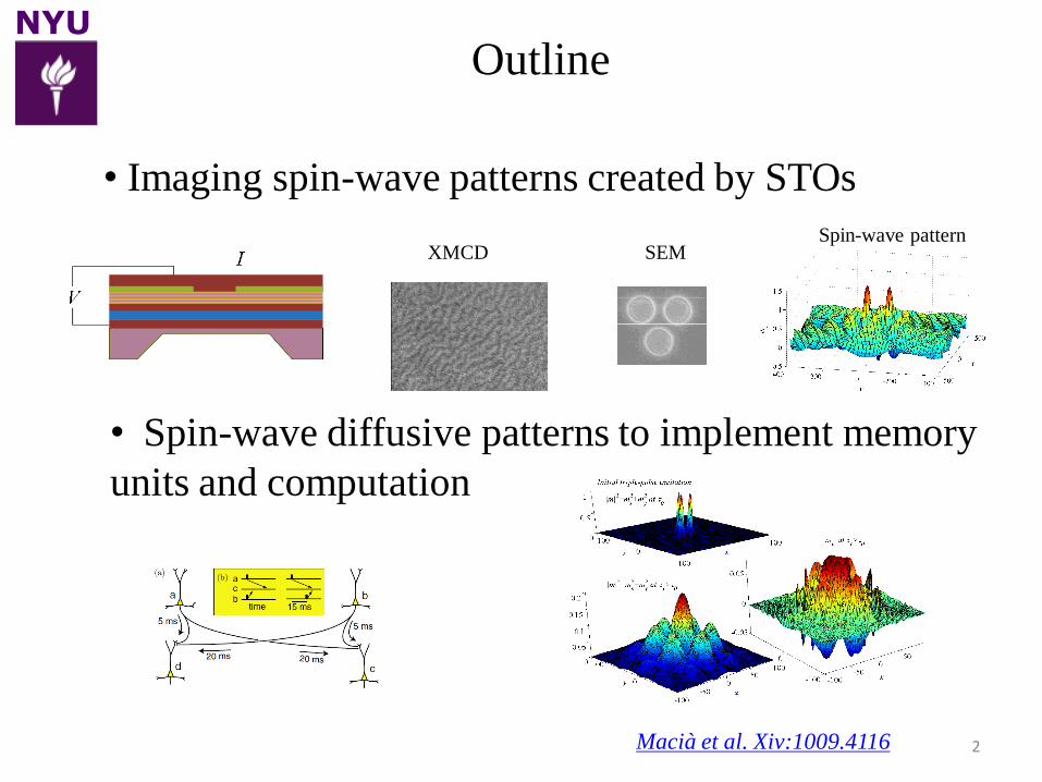
Outline
• Imaging spin-wave patterns created by STOs
• Spin-wave diffusive patterns to implement memory
units and computation
Macià et al. Xiv:1009.4116
XMCD SEMSpin-wave pattern
NYU
3
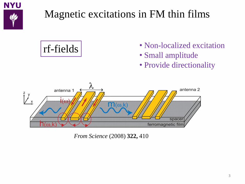
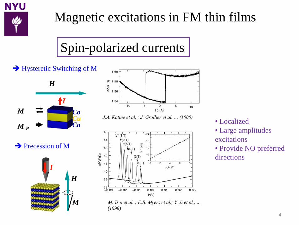
Magnetic excitations in FM thin films
rf-fields • Non-localized excitation
• Small amplitude
• Provide directionality
From Science (2008) 322, 410
NYU
4
Spin-polarized currents
Hysteretic Switching of M
Precession of M
H
I
M
CuCo
Co
I
M
H
M P• Localized
• Large amplitudes
excitations
• Provide NO preferred
directions
Magnetic excitations in FM thin films
M. Tsoi et al. ; E.B. Myers et al.; Y. Ji et al., …
(1998)
J.A. Katine et al. ; J. Grollier et al. … (1000)
NYU
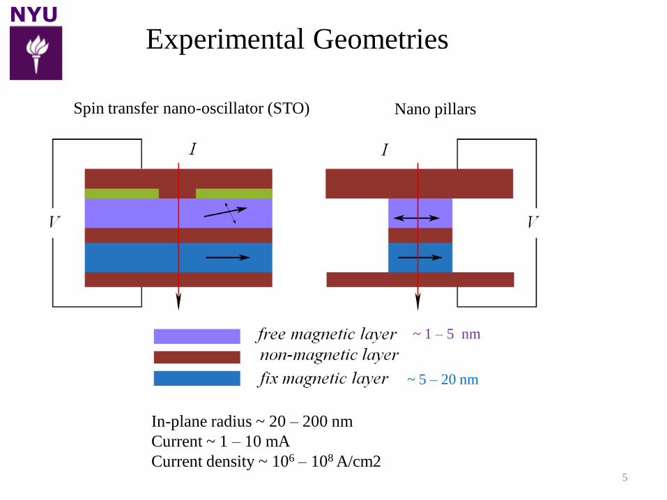
In-plane radius ~ 20 – 200 nm
Current ~ 1 – 10 mA
Current density ~ 106 – 108 A/cm25
~ 1 – 5 nm
~ 5 – 20 nm
Experimental Geometries
Spin transfer nano-oscillator (STO) Nano pillars
NYU
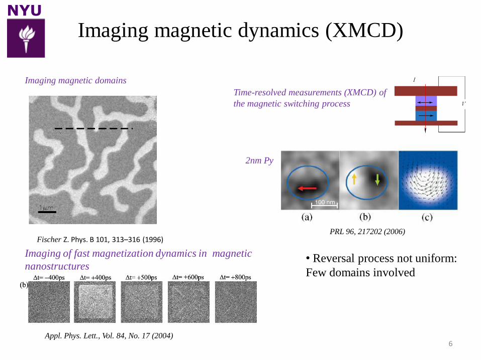
Imaging magnetic dynamics (XMCD)
6
Time-resolved measurements (XMCD) of
the magnetic switching process
Fischer Z. Phys. B 101, 313–316 (1996)PRL 96, 217202 (2006)
2nm Py
Imaging magnetic domains
Imaging of fast magnetization dynamics in magnetic
nanostructures
Appl. Phys. Lett., Vol. 84, No. 17 (2004)
• Reversal process not uniform:
Few domains involved
NYU
7
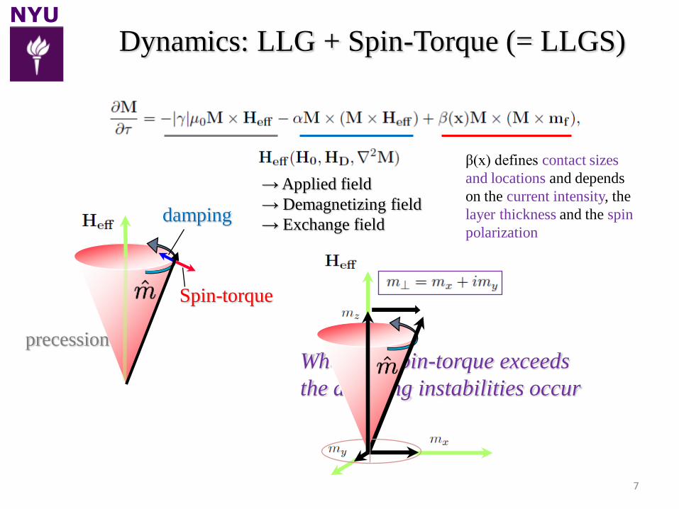
When the spin-torque exceeds
the damping instabilities occur
Dynamics: LLG + Spin-Torque (= LLGS)
damping
precession
Spin-torque
β(x) defines contact sizes
and locations and depends
on the current intensity, the
layer thickness and the spin
polarization
→ Applied field
→ Demagnetizing field
→ Exchange field
NYU
8
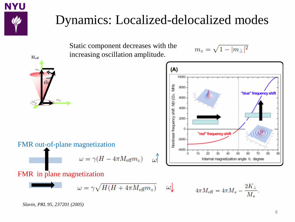
Dynamics: Localized-delocalized modes
Static component decreases with the
increasing oscillation amplitude.
FMR out-of-plane magnetization
FMR in plane magnetization
Slavin, PRL 95, 237201 (2005)
NYU
9
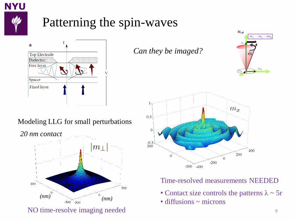
Can they be imaged?
NO time-resolve imaging needed
Time-resolved measurements NEEDED
Patterning the spin-waves
Modeling LLG for small perturbations
(nm)(nm)
20 nm contact
• Contact size controls the patterns λ ~ 5r
• diffusions ~ microns
NYU
10
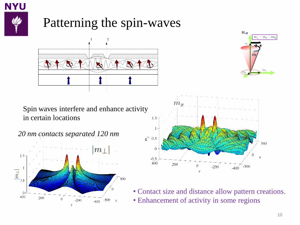
Patterning the spin-waves
Spin waves interfere and enhance activity
in certain locations
• Contact size and distance allow pattern creations.
• Enhancement of activity in some regions
20 nm contacts separated 120 nm
NYU
11
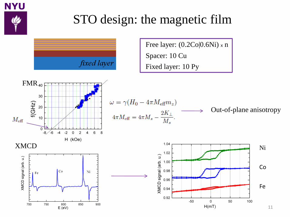
STO design: the magnetic film
FMR
Out-of-plane anisotropy
XMCD
Free layer: (0.2Co|0.6Ni) x n
Fixed layer: 10 Py
Spacer: 10 Cu
Ni
Co
Fe
NYU
12
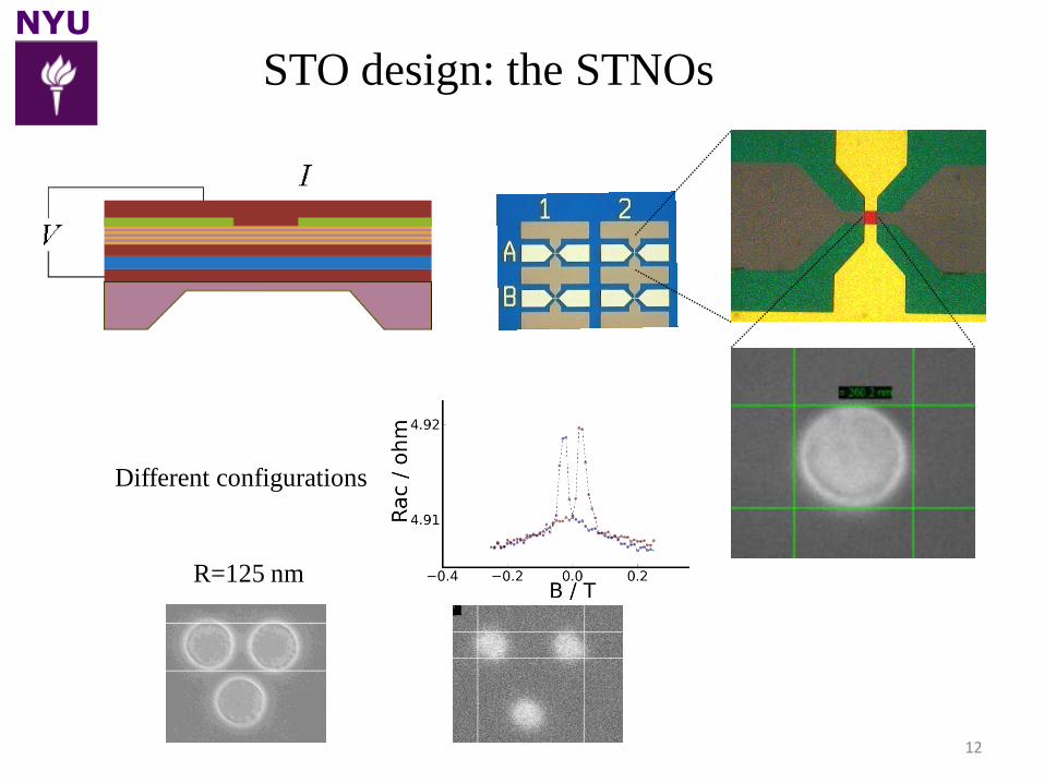
STO design: the STNOs
Different configurations
R=40 nmR=125 nm
NYU
13
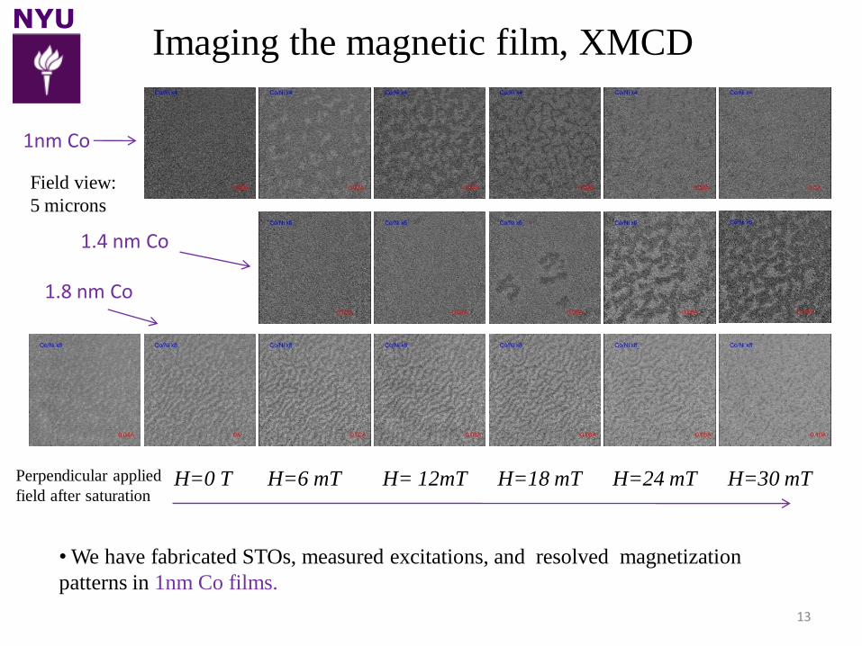
Perpendicular applied
field after saturationH=0 T H=6 mT H=30 mTH=24 mTH=18 mTH= 12mT
1nm Co
1.4 nm Co
1.8 nm Co
Field view:
5 microns
Imaging the magnetic film, XMCD
• We have fabricated STOs, measured excitations, and resolved magnetization
patterns in 1nm Co films.
NYU
14
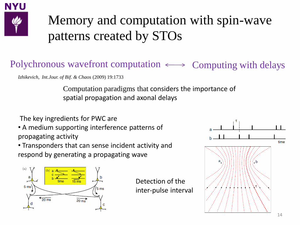
Polychronous wavefront computation Computing with delays
Memory and computation with spin-wave
patterns created by STOs
Izhikevich, Int.Jour. of Bif. & Chaos (2009) 19:1733
Computation paradigms that considers the importance of spatial propagation and axonal delays
The key ingredients for PWC are • A medium supporting interference patterns of propagating activity• Transponders that can sense incident activity and respond by generating a propagating wave
Detection of the inter-pulse interval
NYU
15
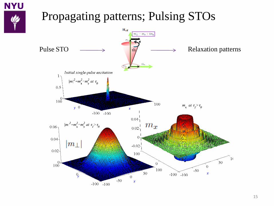
Propagating patterns; Pulsing STOs
Relaxation patternsPulse STO
NYU
16
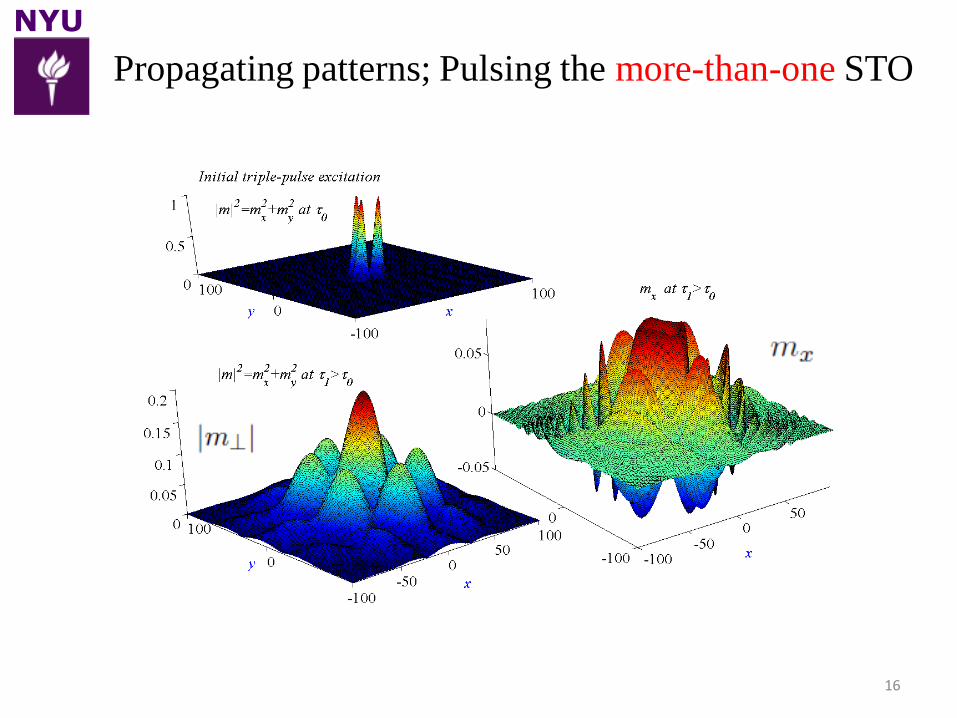
Propagating patterns; Pulsing the more-than-one STO
NYU
17
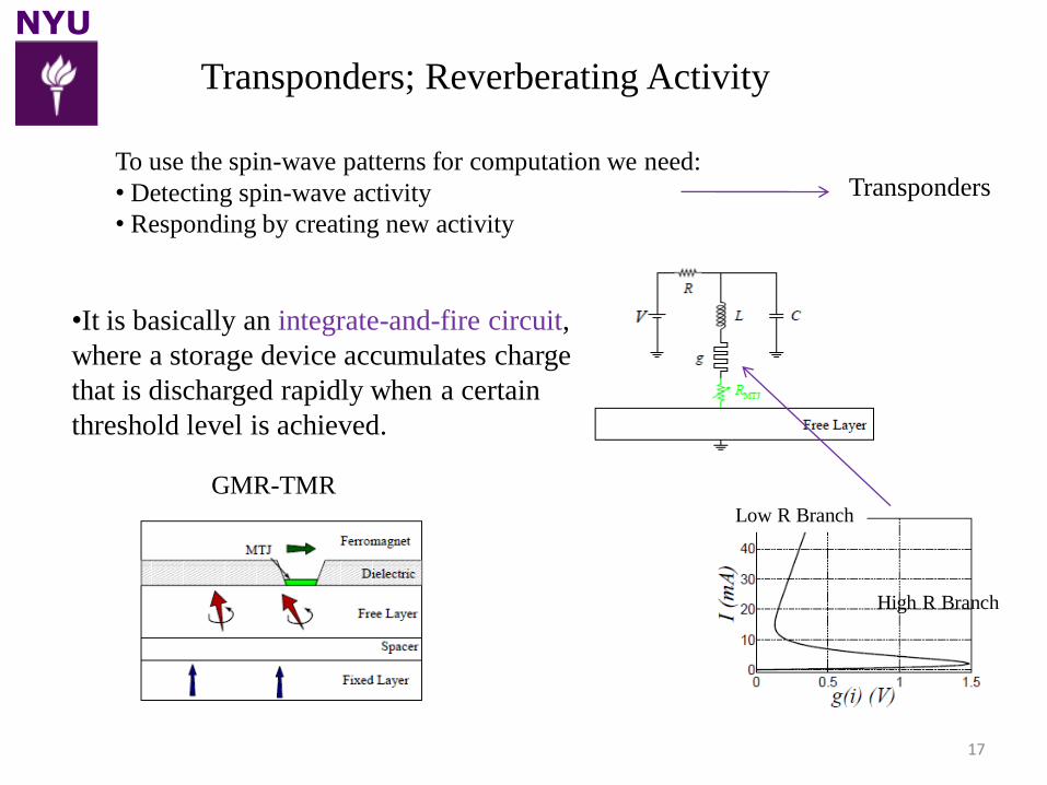
Transponders; Reverberating Activity
•It is basically an integrate-and-fire circuit,
where a storage device accumulates charge
that is discharged rapidly when a certain
threshold level is achieved.
GMR-TMR
High R Branch
To use the spin-wave patterns for computation we need:
• Detecting spin-wave activity
• Responding by creating new activity
Transponders
Low R Branch
NYU
18
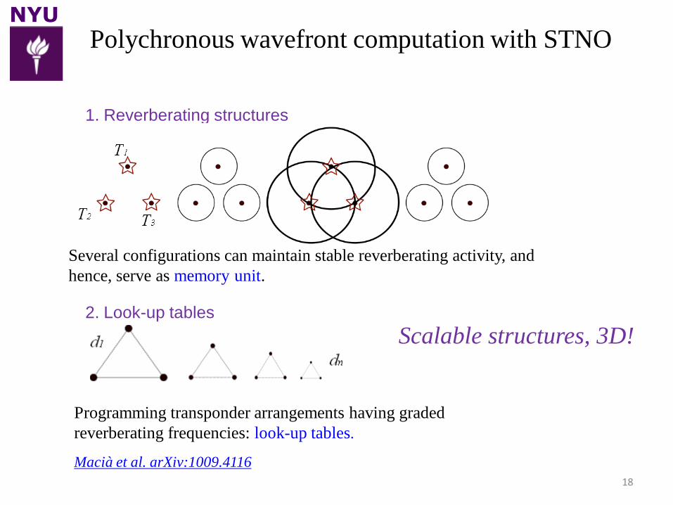
Polychronous wavefront computation with STNO
Scalable structures, 3D!
Macià et al. arXiv:1009.4116
1. Reverberating structures
2. Look-up tables
Several configurations can maintain stable reverberating activity, and
hence, serve as memory unit.
Programming transponder arrangements having graded
reverberating frequencies: look-up tables.
NYU
19
• Fabricated STOs and studied their characteristics
• Imaged 1nm-thick Co Layer
• Modeling shows that spin-wave packets can be tailored
in STO arrays
• Provides a means of implementing Polychronous
Wavefront Computation.
Summary
Macià et al. arXiv:1009.4116