Spill Prevention, Control, and Countermeasure (SPCC) Plan · Spill Prevention, Control, and...
94
Spill Prevention, Control, and Countermeasure (SPCC) Plan January 30, 2018 The University of Texas at Tyler 3900 University Blvd. Tyler, TX 75799 (903) 566-7011
Transcript of Spill Prevention, Control, and Countermeasure (SPCC) Plan · Spill Prevention, Control, and...

Spill Prevention, Control,
and Countermeasure
(SPCC) Plan
January 30, 2018
The University of Texas at Tyler
3900 University Blvd.
Tyler, TX 75799
(903) 566-7011

The University of Texas at Tyler Tyler Campus SPCC Plan
ii
TABLE OF CONTENTS
Professional Engineer Certification .............................................................................................................. iv
General Facility Information ......................................................................................................................... v
Plan Review Matrix ...................................................................................................................................... vi
1.0 INTRODUCTION ................................................................................................................................... 1
2.0 FACILITY DESCRIPTION .................................................................................................................... 2
2.1 Facility Operations ........................................................................................................................ 2
2.2 Drainage Pathways and Distance to Navigable Waters ............................................................... 2
2.3 Site Location Maps ........................................................................................................................ 2
3.0 RESPONSIBILITIES, NOTIFICATIONS AND REPORTING ............................................................... 2
3.1 Responsibilities ............................................................................................................................. 3
3.2 Initial Notifications ......................................................................................................................... 3
3.3 Regulatory and Response Notifications ........................................................................................ 3
3.3.1 Texas Requirements ............................................................................................................. 3
3.3.2 Spills Threatening to Reach Navigable Waters .................................................................... 4
3.3.3 Spills Threatening Human Health ......................................................................................... 5
3.3.4 Commercial Clean-up Contractors ........................................................................................ 5
3.4 Federal Reporting ......................................................................................................................... 5
3.5 State Reporting ............................................................................................................................. 6
4.0 EMERGENCY PROCEDURES ............................................................................................................. 8
5.0 PAST SPILL EXPERIENCE ............................................................................................................... 10
6.0 POTENTIAL SPILL REDUCTION ...................................................................................................... 11
6.1 Oil Capacity and Storage ............................................................................................................ 11
6.2 Bulk Fuel Storage ........................................................................................................................ 16
6.3 Containment ................................................................................................................................ 19
6.3.1 Hydraulic Elevators and Transformers ................................................................................ 19
6.3.2 Waste Kitchen Grease Storage ........................................................................................... 19
6.3.3 Above Ground Storage Drums ............................................................................................ 20
6.3.4 Above Ground Storage Tanks ............................................................................................. 20
6.3.5 Emergency Generator Diesel Fuel Reservoir ........................................................................ 20
6.4 General Practices ........................................................................................................................ 20

The University of Texas at Tyler Tyler Campus SPCC Plan
iii
6.4.1 Oil Transfer Procedures ...................................................................................................... 20
6.4.2 Dike Drainage ...................................................................................................................... 21
6.4.3 Recovered Clean-up Material Disposal .............................................................................. 22
6.4.4 Visiting Vehicle Traffic ......................................................................................................... 22
6.4.5 Drum Handling .................................................................................................................... 22
7.0 INSPECTIONS .................................................................................................................................... 23
7.1 Visual Inspections ....................................................................................................................... 23
7.2 Integrity Testing ........................................................................................................................... 23
8.0 SPILL ABATEMENT EQUIPMENT AND MATERIALS ..................................................................... 25
9.0 SECURITY .......................................................................................................................................... 26
10.0 TRAINING ........................................................................................................................................... 27
11.0 FACILITY RESPONSE PLAN ............................................................................................................ 28
12.0 SPCC PLAN AMENDMENT ............................................................................................................... 29
12.1 Facility Modifications ................................................................................................................... 29
12.2 EPA Requirements ...................................................................................................................... 29
12.3 Five-Year Revisions .................................................................................................................... 29
13.0 IMPLEMENTATION SCHEDULE ....................................................................................................... 30
FIGURES
Figure 1: Facility Drainage and Distance to Navigable Waters ................................................................... 32
Figure 2: Elevator Hydraulic Reservoirs ...................................................................................................... 33
Figure 3: Electrical Transformers ................................................................................................................ 34
Figure 4: Generator Fuel Storage Tanks ..................................................................................................... 34
Figure 5: Bulk Storage Containers ............................................................................................................... 36
APPENDICES
Appendix A: SPCC Regulation 40 CFR Part 112 ........................................................................................... 37
Appendix B: SPCC Rule Cross Reference ..................................................................................................... 68
Appendix C: Spill Reporting Form (Example) .............................................................................................. 77
Appendix D: Inspection and Dike Draining Logs ......................................................................................... 80
Appendix E: Certification of the Applicability of the Substantial Harm Criteria Checklist .......................... 82
Appendix F: Training Roster ........................................................................................................................ 85
Appendix G: Photo Log of Oil Storage Locations ........................................................................................ 87


The University of Texas at Tyler Tyler Campus SPCC Plan
v
GENERAL FACILITY INFORMATION Name and Location of Facility: The University of Texas at Tyler 3900 University Blvd. Tyler, TX 75799 Type of Facility: Educational Facility Telephone Number: 903-566-7300 Normal Operating Schedule: 24 hours/day; 7 days/week; 52 weeks/year Name and Address of Owner/Operator: The University of Texas at Tyler 3900 University Blvd. Tyler, TX 75799 Designated Person Responsible for Paula Tate Spill Prevention at the Facility: Environmental Health & Safety Date of Initial Operation of Facility: 1971 Oil Spill History: N/A Receiving Waters: Gilley Creek, Lake Tyler
MANAGEMENT APPROVAL
The University of Texas at Tyler is committed to the prevention of discharges of oil to navigable waters
and the environment, and maintains the highest standards for spill prevention control and
countermeasures through regular reviews, updating and implementation of this SPCC Plan for its facility
in Tyler, Texas. This SPCC Plan will be implemented as herein described. By signing this document, I
certify that I am thoroughly familiar with this SPCC Plan.
Authorized Facility
Representative: William J. O’Donnell Title: Vice President for Business Affairs
Signature: Date:
03-14-2018

The University of Texas at Tyler Tyler Campus SPCC Plan
vi
PLAN REVIEW MATRIX
Review Date
Reviewer Signature Revision Required
Reason for Revision Revision Number
Revision Date
7/20/2017
Revision needed
Revision not needed
Sign: _________________
Yes Site maintains more than 10,000 gallons of oil
1
1/30/2018
Revision needed
Revision not needed
Sign: _________________
No
Revision needed
Revision not needed
Sign: _________________
Revision needed
Revision not needed
Sign: _________________
Revision needed
Revision not needed
Sign: _________________
Revision needed
Revision not needed
Sign: _________________
Revision needed
Revision not needed
Sign: _________________
CERTIFICATION REQUIREMENTS
A Professional Engineer’s certification is required if: (1) the site maintains oil in excess of 10,000 gallons, (2) the site has a single discharge exceeding 1,000 gallons or two discharges each exceeding 42 gallons within a twelve month period in the three years prior to the SPCC Plan certification date, or (3) the SPCC Plan deviates from any requirements as allowed by 40 CFR 112.7(a)(2) and 112.7(d) except as provided in 40 CFR 112.6(c).

The University of Texas at Tyler Tyler Campus SPCC Plan
1
1.0 INTRODUCTION
The Oil Pollution Prevention Regulation in 40 CFR Part 112 was developed in order to (1) prevent oil
discharges from reaching navigable waterways (defined to include, but not limited to: lakes, rivers,
streams, and wetlands) and adjoining shorelines, and (2) to ensure effective response to oil discharges.
Required under this rule is the development of a Spill Prevention Control and Countermeasure Plan
(SPCC) for applicable owners, users and/or operators of facilities that could possibly discharge oil in
harmful quantities into navigable waterways.
On January 14, 2010, the Environmental Protection Agency (EPA) put into effect a final rule
amending the SPCC regulations. Under the SPCC requirements, owners or operators of facilities that
“drill, produce, gather, store, use, process, refine, transfer, distribute, or consume oil and oil products”
must prepare a SPCC if any of the following storage practices apply:
• greater than 1,320 gallons of oil is stored in above-ground containers/tanks, or
• greater than 42,000 gallons of oil is stored in underground containers/tanks provided the underground storage tank (UST) is not subject to the technical requirements of the UST regulations, 40 CFR Part 280 or 281.
In accordance with SPCC regulations, only containers of oil (defined as “oil of any kind or in any
form, including, but not limited to; petroleum, fuel, oil, sludge, synthetic oils, mineral oils, oil refuse,
or oil mixed with wastes other than dredged spoil”) with a capacity of 55 gallons or greater are counted
in the calculation of the 1,320-gallon threshold. All containers with a storage capacity of less than
55 gallons of oil are exempt from the SPCC regulations. A complete copy of the SPCC regulations
is included in Appendix A.
The University of Texas at Tyler (UT Tyler) is required to prepare, maintain, and follow a SPCC plan
since greater than 1,320 gallons of petroleum products are stored above ground and the discharge of oil
could potentially impact Gilley Creek and ultimately Lake Tyler, located southeast of the campus.

The University of Texas at Tyler Tyler Campus SPCC Plan
2
2.0 FACILITY INFORMATION
2.1 Facility Description
The University of Texas at Tyler Main Campus is located on the southeast side of Tyler, Texas. The
campus encompasses approximately 294 acres with interior paved roads and parking surfaces and
multiple buildings surrounded by green areas and woodlands. The campus is bordered by Varsity Drive to
the north, University Boulevard (Spur 248) to the south, Old Omen Road to the east, and Patriot Drive to
the west.
The University’s total above ground oil storage capacity is approximately 18,850 gallons and includes
the following containers with capacities at or exceeding 55-gallons:
• Hydraulic reservoirs (~5,105 gallons) associated with elevators;
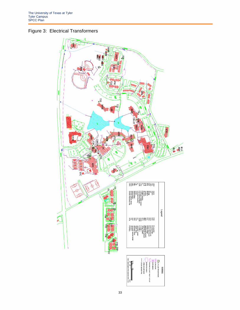
• Electrical transformers (~9,470 gallons) filled with dielectric fluid (non-PCB);
• Diesel reservoirs associated with emergency generators (~2,610 gallons);
• Various aboveground storage tanks and drums (~1,465 gallons); and
• Used kitchen grease containers (~200 gallons).
2.2 Drainage Pathways and Distance to Navigable Waters
Figure 1 depicts the facility drainage, based on a visual observation of site contours is directed to the
south of the property towards Gilley Creek. Storm drains which direct flow to Gilley Creek are located
throughout the campus. A large volume spill could potentially impact Gilley Creek and/or Lake Tyler.
2.3 Site Location Maps
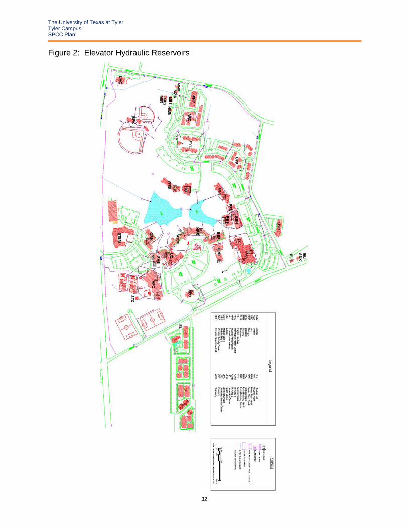
• Figure 2 Elevator Hydraulic Reservoirs
• Figure 3 Electrical Transformers
• Figure 4 Generator Fuel Storage Tanks
• Figure 5 Bulk Storage Containers
A photo log of the oil storage locations is included as Appendix G. Also note that Figures 1 through 5
have been provided at the end of the text for convenience to the reader and user of this SPCC Plan.

The University of Texas at Tyler Tyler Campus SPCC Plan
3
3.0 RESPONSIBILITIES, NOTIFICATIONS, AND REPORTING
3.1 Responsibilities
The duties of the Primary Emergency Coordinator and his/her alternate are to routinely inspect all storage
and handling facilities and take corrective action when conditions warrant. In addition, the Primary
Emergency Coordinator will participate in, set up and maintain: necessary spill emergency procedures;
recordkeeping; personnel training; SPCC Plan Reviews and amendments (if required); and reporting
requirements.
In the event of an oil release, appropriate staff of UT Tyler shall carry out the procedures outlined herein
under the direction of the Primary Emergency Coordinator or his/her alternates(s).
3.2 Initial Notifications
In the event of any emergency or occurrence related to the release or threatened release of
petroleum products, the following persons shall be notified immediately:
Name Phone Number
UT Tyler Police 903-566-7300
Paula Tate 903-566-7401
The Primary Emergency Coordinator and his/her Alternate Emergency Coordinator have been
chosen based on the following qualifications:
• Is on-site or on call at all times;
• Is familiar with the facility layout;
• Is knowledgeable of the locations and characteristics of the materials handled;
• Is familiar with all operations and activities at the facility;
• Is thoroughly familiar with emergency plans;
• Is knowledgeable of the locations of all records; and
• Has the authority to commit facility resources in the event of an emergency.
The Emergency Coordinators or designated Alternates will then notify the proper off-site authorities
about the actual emergency, following their initial action at the site.
UT Tyler staff does not respond to major spills. Response staff, along with the department involved, will
contact campus police who will alert UT Tyler Environmental Health and Safety (EH&S) as necessary. If
the spill is beyond the capacity for campus staff to mitigate, one of the commercial cleanup
contractors will be contacted to provide a response.
3.3 Regulatory and Response Notifications
The guidelines in this section apply to all spills: petroleum products, chemicals, and/or non- hazardous and hazardous waste. 3.3.1 Texas Requirements (Reference 30 TAC 327) The Texas Commission on Environmental Quality (TCEQ) shall be notified as soon as possible but no later than 24 hours after the discovery of a spill. The TCEQ defines a reportable spill as:

The University of Texas at Tyler Tyler Campus SPCC Plan
4
Spill Type Reportable Quantity
Petroleum Product and Used Oil
- 25 gallons onto land; or
- quantity sufficient to create a sheen for spills into water
Crude oil and all other oils not defined as used oil or petroleum product
- 210 gallons onto land; or
- Quantity sufficient to create a sheen for spills into water
Hazardous Substances
- a reportable quantity as defined in Table 302.4 in 40 CFR 302.4 for spills onto land; or
- whichever is less; 100 pounds or the reportable quantity as defined in Table 302.4 in 40 CFR 302.4 for spills into water
All other substances - 100 pounds if spilled into water
State Emergency Response (TCEQ) (24 Hrs) Phone: (800) 832-8224
Tyler Regional TCEQ Office Phone: (903) 535-5100
The following information will be provided:
• Name, title, affiliation, address and telephone number of reporter;
• For discharges from sites on land, the name of the site, street address, municipality, and the county;
• For discharges on, under or into water, the name of the body of water, location of the discharge with reference to a fixed point, description of the area which the discharge may reach;
• Date and time at which the discharge began, the date and time at which the discharge was discovered, and, if the discharge has ended, the date and time at which it ended;
• Common name and quantity of material(s) involved, to the extent known;
• An estimate of the quantity discharged;
• The identity of any governmental representatives, including authorities or third parties, responding to the spill;
• Any actions taken to contain, clean up and remove the hazardous substance(s) discharged;
• The possible hazards to human health or the environment outside the facility;
• The extent of injuries, if any; and
• The name and address of any person responsible for the discharge (i.e. source of the spill). 3.3.2 Spills Threatening to Reach Navigable Waters In the event that a spill of material of any amount threatens to reach navigable waters, the National Response Center in Washington, DC shall be contacted within 24 hours of the event:
Authority Phone Number
National Response Center (NRC) (800) 424-8802
EPA Region VI (800) 887-6063

The University of Texas at Tyler Tyler Campus SPCC Plan
5
If possible, UT Tyler personnel will be ready to report the following information to the NRC:
• Your name, location, organization, and telephone number;
• Name and address of the party responsible for the incident;
• Date and time of the incident;
• Location of the incident;
• Source and cause of the release or spill;
• Types of material(s) released or spilled;
• Quantity of materials released or spilled;
• Danger or threat posed by the release or spill;
• Number and types of injuries (if any);
• Weather conditions at the incident location;
• Any other information that may help emergency personnel respond to the incident.
Navigable waters of United States are defined in 40 CFR Part 110.1 to include interstate waterways or
intrastate waterways including lakes, rivers and streams which may be utilized by interstate
travelers for recreational purposes. Navigable waters also include lakes, rivers, and streams from
which fish or shellfish are taken. The complete definition may be found in Section 502(7) of the
Federal Water Pollution Control Act. In the event of a large volume release, oil products could
potentially enter Gilley or Lake Tyler. Detailed information regarding individual storage areas is
provided in Section 6.0.
3.3.3 Spills Threatening Human Health
In the event the Emergency Coordinator or designated alternate determines that the release of
materials threatens human health outside the facility and evacuation may be necessary, he/she will also
report his findings to the local authorities, as appropriate:
Authority Phone Number
State Emergency Response Commission 800-832-8224
Tyler Fire Department 903-531-1319
Smith County LEPC 903-566-6600
3.3.4 Commercial Clean-Up Contractors
Should a spill contractor be needed, UT Tyler will contact one of the following contractors:
Contractor Phone Number
SWS Environmental Services 1-877-742-4215
SET Environmental Inc. 1-877-437-7455
3.4 Federal Reporting
After a spill or release of greater than 1,000 gallons or after two spills of greater than 42 gallons within
any twelve-month period, or if the spill impacted a navigable waterway, the Emergency Coordinator will
report the event(s) to the following agency within 60 days.

The University of Texas at Tyler Tyler Campus SPCC Plan
6
The Regional Administrator
U.S. Environmental Protection Agency – Region VI
1445 Ross Avenue, Suite 1200
Dallas, Texas 75202
Phone: 1-800- 887-6063
The EPA report will include:
• Name of the facility;
• Your name;
• Location of the facility;
• Maximum storage or handling capacity of the facility and normal daily throughput;
• Corrective action and countermeasures you have taken, including a description of equipment
repairs and replacement;
• An adequate description of the facility, including maps, flow diagrams, and topographical
maps, as necessary;
• The cause of the discharge, including a failure analysis of the system or subsystem in which the
failure occurred;
• Additional preventive measures you have taken or contemplated to minimize the possibility of
recurrence; and
• Such other information as the Regional Administrator may reasonably require pertinent to the
Plan or spill event.
As required by EPA Federal Regulation 40 CFR 112.4(c), a copy of the EPA report will also be
submitted to the TCEQ through the Regional Office.
Texas State Emergency Response Commission (SERC) who will contact TCEQ Emergency Response
Section at the following address:
TCEQ, Region 5
Attn: Emergency Response Section
2916 Teague Drive
Tyler, TX 75701-3734
Phone: 903-595-5100
If 1,000 gallons or more of material is spilled to a navigable waterway, or there are two or more
reportable spills (to the National Response Center) in a year, the EPA may conduct an inspection of the
site and review this Plan. Following the inspection and review, the EPA may require facility
modifications and/or operational changes to minimize the possibility of future spills.
3.5 State Reporting
For all spills reported to the TCEQ, UT Tyler will submit written information in the form of a letter
describing the details of the discharge or spill and supporting the adequacy of the response action within
30 days of the discovery of the reportable discharge or spill.

The University of Texas at Tyler Tyler Campus SPCC Plan
7
The documentation shall contain one of the following items:
• A statement that the discharge or spill response action has been completed and a description of
how the response action was conducted. The statement shall include the initial report
information outlined in Section 3.2 of this plan;
• A request for an extension of time to complete the response action, along with the reasons for
the request. The request shall also include a projected work schedule outlining the time required
to complete the response action. The executive director may grant an extension up to six
months from the date the spill or discharge was reported. Unless otherwise notified by the
appropriate regional manager or the Emergency Response Team, UT Tyler shall proceed
according to the terms of the projected work schedule; or
• A statement that the discharge or spill response action has not been completed nor is it
expected to be completed within the maximum allowable six month extension. The statement
shall explain why completion of the response action is not feasible and include a projected work
schedule outlining the remaining tasks to complete the response action. This information will
also serve as notification that the response actions to the discharge or spill will be conducted
under the Texas Risk Reduction Program rules in Chapter 350 of the Texas Administrative
Coalition. This report will be mailed to:
TCEQ, Region 5
Attn: Emergency Response Section
2916 Teague Drive
Tyler, TX 75701-3734

The University of Texas at Tyler Tyler Campus SPCC Plan
8
4.0 EMERGENCY RESPONSE
In the event of a spill or release, the emergency procedures outlined in the Emergency Procedures flow
chart provided on the following page will be followed. A copy of the emergency procedure flow chart
will be in or near the Primary Emergency Coordinator’s office, as well as all of the alternates. If any
employee discovers a spill or release, it will immediately be reported to the Primary Emergency
Coordinator. If the Primary Emergency Coordinator or alternate determines that the spill or release
cannot be handled by on-site personnel and/or may be a threat to either health or the environment, the
listed professional spill response contractor (previously listed in Section 3.3.4) will be contacted.
The Primary Emergency Coordinator or Alternate is responsible for determining when a spill event has
concluded or is under control sufficiently such that normal activities and personnel presence may be
safely resumed.
Only if the spill or release can be safely handled by on-site personnel, the following actions may be
conducted:
• While awaiting arrival of the Emergency Coordinator or designated Alternates, personnel
shall commence containment activities immediately, using all available man-power and spill
response materials in the adjacent area of the spill.
• Immediate containment of the spill shall be initiated such as blocking of adjacent interior floor
and exterior storm drains, constructing dikes, and using all available containment materials
on hand.
Contained materials will be removed as soon as possible and placed into proper containers, such as 55-
gallon drums. All equipment and manpower shall be utilized to remove spilled materials promptly and
in a safe manner. All drums used to contain spilled waste will be transported to the waste storage
area for eventual off-site disposal by a licensed transporter.

The University of Texas at Tyler Tyler Campus SPCC Plan
9
EMERGENCY PROCEDURE FLOWCHART: SPILL AND/OR RELEASE OF HAZARDOUS MATERIAL
CONTACT EMERGENCY COORDINATOR AND/OR SECONDARY COORDINATOR:
1) Emergency Coordinator – UT Tyler Campus Police 903-566-7300 (24-Hour)
2) Alternate Emergency Coordinator – Paula Tate 903-566-7011
EMERGENCY COORDINATOR OR ALTERNATE OBTAINS THE FOLLOWING
INFORMATION:
1) Nature of emergency; 2) Location of emergency; 3) Size and extent of emergency; and 4) Whether anyone is injured or other hazardous situations
PERSONNEL INJURED? YES
NO
EMERGENCY COORDINATOR / ALTERNATE CONTACTS THE FOLLOWING:
EMS/FIRE: 9-1-1
POISON CONTROL CENTER 1-800-343-272
BE PREPARED TO GIVE: NATURE OF EMERGENCY, NAME, ADDRESS, EXTENT OF INJURIES, AND POSSIBLE HAZARDOUS MATERIALS INVOLVED AND QUANTITY
IF NECESSARY, THE EMERGENCY COORDINATOR WILL ACTIVATE INTERNAL FACILITY
ALARMS AND/OR COMMUNICATIONS SYSTEMS TO NOTIFY ALL PERSONNEL OF EVACUATION
IS THE SPILL AN INCIDENTAL RELEASE THAT CAN BE ABSORBED, NEUTRALIZED, OR OTHERWISE CONTROLLED
AT THE TIME OF RELEASE BY EMPLOYEES IN THE IMMEDIATE RELEASE AREA OR BY MAINTENANCE
PERSONNEL UTILIZING EQUIPMENT ON-HAND WITHOUT JEOPARDIZING THEIR HEALTH OR SAFETY?
BEGIN CONTAINING SPILL, CLEAN-UP SPILLED MATERIAL, AND STORE PROPERLY FOR DISPOSAL.
EMERGENCY COORDINATOR / ALTERNATE CONTACTS THE STATE AS NECESSARY (SECTION 3.3)
TCEQ - STATE: 1-800-832-8224
TCEQ - TYLER OFFICE: 903-595-5100
EMERGENCY COORDINATOR / ALTERNATE
CONTACTS:
TYLER FIRE DEPARTMENT: 903-531-1319
SMITH COUNTY LEPC: 903-566-6600
SPILL CONTRACTOR:
SWS Environmental Services 1-877-742-4215
HAS SPILL REACHED OR THREATENED GILLEY CREEK OR HAS ENTERED THE SOIL, WATER OR VOLITILIZED TO THE AIR?
YES
EMERGENCY COORDINATOR / ALTERNATE CONTACTS THE
FOLLOWING: NATIONAL RESPONSE CENTER: 800-424-8802
SPILL CONTAMINATED MATERIAL CLEANED
UP AND STORED PROPERLY FOR DISPOSAL
REPORTING REQUIREMENTS MET (SECTION 3.4 AND 3.5) AND SPILL FORM (APPENDIX C) COMPLETED
NO
NO
YES

The University of Texas at Tyler Tyler Campus SPCC Plan
10
5.0 PAST SPILL EXPERIENCE
According to 40 CFR 112.7(a), a facility which has experienced one or more spill events within twelve
months prior to the effective date of this part should include a written description of each such spill,
corrective action taken, and plans for preventing a recurrence.
In preparing this plan, no spills having occurred within the past twelve months were identified. Any future
spills will be documented using the Spill Form in Appendix C.

The University of Texas at Tyler Tyler Campus SPCC Plan
11
6.0 POTENTIAL SPILL PREDICTION
6.1 Oil Capacity and Storage After a review of the UT Tyler campus, it was determined that all petroleum products are stored and
managed at the facility within bulk storage and oil filled operational equipment. Provided in Table 1 is a
summary of the oil capacities and containment and control practices identified at UT Tyler. At any one
time, a total of approximately 18,850 gallons of fuel/oil is stored at the facility above ground. Tables 1A
and 1B describe the potential type of failure(s), the estimated amount of material which may be released,
the probable flow direction if a spill should occur, and existing secondary containment measures in each
area of concern.
Oil filled operational equipment includes any oil storage container in which the oil is present solely to
support the function of the apparatus or the device. While oil-filled equipment is not subject to the bulk
storage container requirements, it must still meet the requirements for general secondary containment.
General secondary containment may include:
• Dikes, berms, or retaining walls sufficiently impervious to contain oil;
• Curbing
• Culverting, gutters, or other drainage systems;
• Weirs, booms, or other barriers;
• Spill diversion ponds;
• Retention ponds; or
• Sorbent materials.
Table 1A provides a description of measures for avoiding and/or containing the release of materials
from the facility associated with oil filled operational equipment. In the event of catastrophic failure and
release of oil, the equipment will immediately cease to operate, or “blow” in the case of transformers, in
these instances the release would be immediately observed and addressed with response kits by EH&S
within 5 minutes.
The local electrical utility provider, Oncor, owns one oil filled electrical transformer in the area of the
Alumni House (ALU), and all transformers on the Eagles Landing (EL) property. In the event of a release
from these transformers it is the responsibility of Oncor to conduct all response, repair, and reporting
associated with any releases from the transformer.
Oncor Reporting Division Phone Number
New Construction 1-888-222-8045

The University of Texas at Tyler Tyler Campus SPCC Plan
12
TABLE 1A – OIL FILLED OPERATION EQUIPMENT OIL STORAGE POTENTIAL SPILL PREDICTION AND CONTROL SUMMARY
The University of Texas at Tyler
ELEVATOR HYDRAULIC RESERVOIRS (~5,105 gallons)
Area/Location Source Potential Type
of Failure
Potential Spill Volume
(gal.)
Flow Direction and Distance to Closest Stormwater Drain
Secondary Containment
E1
ADM Hydraulic Oil
Reservoir/Pump failure 165 Concrete Floor,
No access to stormwater
A,B Spill during oil transfer 17
E2
ALU Hydraulic Oil
Reservoir/Pump failure 220 Concrete Floor,
No access to stormwater
A,B Spill during oil transfer 22
E3
BEP Hydraulic Oil
Reservoir/Pump failure 110 Concrete Floor,
No access to stormwater
A,B Spill during oil transfer 11
E4
BRB 2nd Floor Hydraulic Oil
Reservoir/Pump failure 180 Concrete Floor,
No access to stormwater
A,B Spill during oil transfer 18
E5
BUS Hydraulic Oil
Reservoir/Pump failure 75 Concrete Floor,
No access to stormwater
A,B Spill during oil transfer 8
E6
FAC Hydraulic Oil
Reservoir/Pump failure 145 Concrete Floor,
No access to stormwater
A,B Spill during oil transfer 15
E7
FAC Hydraulic Oil
Reservoir/Pump failure 150 Concrete Floor,
No access to stormwater
A,B Spill during oil transfer 15
E8
FAC Hydraulic Oil
Reservoir/Pump failure 220 Concrete Floor,
No access to stormwater
A,B Spill during oil transfer 22
E9
HPC Hydraulic Oil
Reservoir/Pump failure 225 Concrete Floor,
No access to stormwater
A,B Spill during oil transfer 23
E10
HPC Hydraulic Oil
Reservoir/Pump failure 225 Concrete Floor,
No access to stormwater
A,B Spill during oil transfer
23
E11
HPR Hydraulic Oil
Reservoir/Pump failure
100 Concrete Floor, No access to stormwater
A,B Spill during oil transfer
10
E12
LIB
Reservoir #1
Hydraulic Oil
Reservoir/Pump failure
115 Concrete Floor, drain 5’ away A,C2 Spill during oil
transfer 12

The University of Texas at Tyler Tyler Campus SPCC Plan
13
TABLE 1A – OIL FILLED OPERATION EQUIPMENT OIL STORAGE
POTENTIAL SPILL PREDICTION AND CONTROL SUMMARY
The University of Texas at Tyler
Area/Location Source Potential Type of Failure
Potential Spill Volume
(gal.)
Flow Direction and Distance to Closest Stormwater Drain
Secondary Containment
E13
LIB
Reservoir #2
Hydraulic Oil
Reservoir/Pump failure
115 Concrete Floor, drain 5’ away A, C2 Spill during oil
transfer 12
E14
ORH
Reservoir #1
Hydraulic Oil
Reservoir/Pump failure
200 Concrete Floor, No access to stormwater
A,B Spill during oil transfer
20
E15
ORH
Reservoir #2
Hydraulic Oil
Reservoir/Pump failure
200 Concrete Floor, No access to stormwater
A,B Spill during oil transfer
20
E16
PHE Hydraulic Oil
Reservoir/Pump failure
100 Concrete Floor, No access to stormwater
A,B Spill during oil transfer
10
E17
RBN
Reservoir #1
Hydraulic Oil
Reservoir/Pump failure
400 Concrete Floor, No access to stormwater
A,B Spill during oil transfer
40
E18
RBN
Reservoir #2
Hydraulic Oil
Reservoir/Pump failure
400 Concrete Floor, No access to stormwater
A,B Spill during oil transfer
40
E19
RBS
Reservoir #1
Hydraulic Oil
Reservoir/Pump failure
400 Concrete Floor, No access to stormwater
A,B Spill during oil transfer
40
E20
RBS
Reservoir #2
Hydraulic Oil
Reservoir/Pump failure
400 Concrete Floor, No access to stormwater
A,B Spill during oil transfer
40
E21
UC
Exterior Freight
Hydraulic Oil
Reservoir/Pump failure
200 Concrete Floor, No access to stormwater
A,B Spill during oil transfer
20
E22
UC
Kitchen/Freight
Hydraulic Oil
Reservoir/Pump failure
170 Concrete Floor, No access to stormwater
A,B Spill during oil transfer
17
E23
UC Hydraulic Oil
Reservoir/Pump failure
165 Concrete Floor, No access to stormwater
A,B Spill during oil transfer
17
E24
WTB Hydraulic Oil
Reservoir/Pump failure
125 Concrete Floor, No access to stormwater
A,B Spill during oil transfer
13
E25
WTB Hydraulic Oil
Reservoir/Pump failure
300 Concrete Floor, No access to stormwater
A,B Spill during oil transfer
30

The University of Texas at Tyler Tyler Campus SPCC Plan
14
TABLE 1A – OIL FILLED OPERATION EQUIPMENT OIL STORAGE
POTENTIAL SPILL PREDICTION AND CONTROL SUMMARY
The University of Texas at Tyler
ELECTRICAL TRANSFORMERS (~9,470 gallons)
Area/Location Source Potential Type of
Failure
Potential Spill
Volume (gal.)
Flow Direction and Distance to Closest Stormwater Drain
Secondary Containment
T1
ADM Mineral Oil
Reservoir/Pump failure
340 In concrete pit,
floor drain 5’ away A
Spill during oil transfer
34
T2
ARC Envirotemp
Reservoir/Pump failure
377
West 200’ to creek A Spill during oil
transfer 38
T3
BEP Mineral Oil
Reservoir/Pump failure
207
East 20’ A Spill during oil
transfer 21
T4
BPK Mineral Oil
Reservoir/Pump failure
333
West to street A Spill during oil
transfer 33
T5
BRB Mineral Oil
Reservoir/Pump failure
259
North 60’ A Spill during oil
transfer 26
T6
BUS Mineral Oil
Reservoir/Pump failure
200 North to parking lot
then to street A
Spill during oil transfer
20
T19
FAC Mineral Oil
Reservoir/Pump failure
408 West-southwest 20’
to storm water sump A
Spill during oil transfer
41
T20
HPC Mineral Oil
Reservoir/Pump failure
443 None in Immediate
Vicinity A
Spill during oil transfer
44
T21
HPC Mineral Oil
Reservoir/Pump failure
443 None in Immediate
Vicinity A
Spill during oil transfer
44
T22
HPR Mineral Oil
Reservoir/Pump failure
340 In concrete pit
floor drain 5’ away A
Spill during oil transfer
34
T23
LIB Mineral Oil
Reservoir/Pump failure
430 Curb inlet 100’ northeast A
Spill during oil transfer
43
T24
ORH Mineral Oil
Reservoir/Pump failure
305 South 130 yard to curb
inlet A
Spill during oil transfer
31

The University of Texas at Tyler Tyler Campus SPCC Plan
15
TABLE 1A – OIL FILLED OPERATION EQUIPMENT OIL STORAGE
POTENTIAL SPILL PREDICTION AND CONTROL SUMMARY
The University of Texas at Tyler
Area/Location Source Potential Type of
Failure
Potential Spill
Volume (gal.)
Flow Direction and Distance to
Closest Stormwater Drain
Secondary Containment
T25
PHY Mineral Oil
Reservoir/Pump failure
140 West 110’ to creek A
Spill during oil transfer
14
T26
PPN Mineral Oil
Reservoir/Pump failure
639 East 75’ A
Spill during oil
transfer 64
T27
PPN Mineral Oil
Reservoir/Pump failure
639 East 75’ A
Spill during oil transfer
64
T28
PPS
(On the Roof)
Mineral Oil
Reservoir/Pump failure
400
Roof drain A Spill during oil
transfer 40
T29
PPS
(On the Roof)
Mineral Oil
Reservoir/Pump failure
570 Roof drain
A Spill during oil
transfer 57
T30
PPS
(On the Roof)
Mineral Oil
Reservoir/Pump failure
271 Roof drain
A Spill during oil
transfer 27
T31
PPS
(On the Roof)
Mineral Oil
Reservoir/Pump failure
351 Roof drain
A Spill during oil
transfer 35
T32
PVL Mineral Oil
Reservoir/Pump failure
111 West 150’ to
stormwater inlet A
Spill during oil transfer
11
T33
UC Envirotemp
Reservoir/Pump failure
255 Northwest 25’ A
Spill during oil transfer
26
T34
UC Envirotemp
Reservoir/Pump failure
484 South 15’ A
Spill during oil transfer
48
T35
WTB Mineral Oil
Reservoir/Pump failure
481 Conveyance to Harvey Lake 25’
southeast
A Spill during oil
transfer 48
Secondary Containment Legend
A To be contained by spill kit absorbent materials
B Spill contained by impervious nature of building’s floor and walls
C2 Sized Secondary containment via constructed berm
The University of Texas at Tyler Tyler Campus SPCC Plan
16
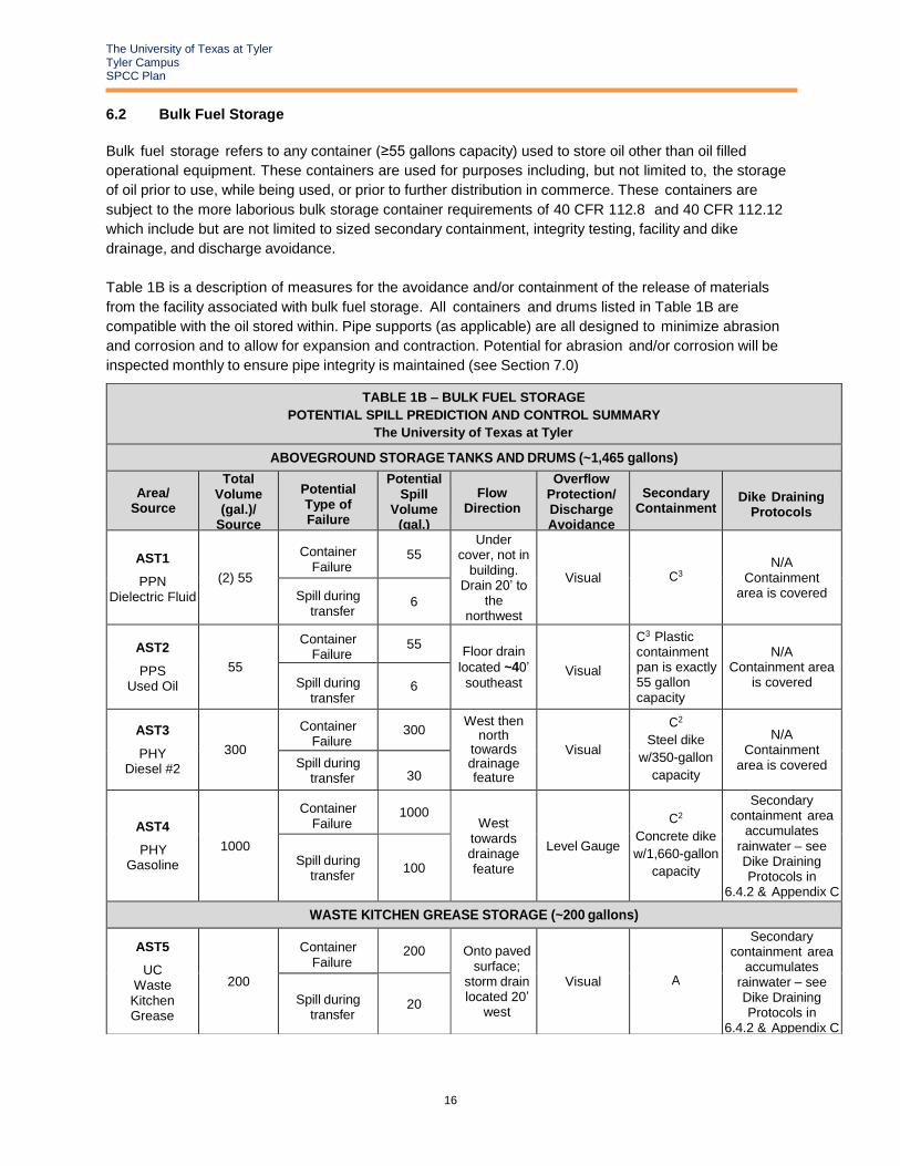
6.2 Bulk Fuel Storage
Bulk fuel storage refers to any container (≥55 gallons capacity) used to store oil other than oil filled
operational equipment. These containers are used for purposes including, but not limited to, the storage
of oil prior to use, while being used, or prior to further distribution in commerce. These containers are
subject to the more laborious bulk storage container requirements of 40 CFR 112.8 and 40 CFR 112.12
which include but are not limited to sized secondary containment, integrity testing, facility and dike
drainage, and discharge avoidance.
Table 1B is a description of measures for the avoidance and/or containment of the release of materials
from the facility associated with bulk fuel storage. All containers and drums listed in Table 1B are
compatible with the oil stored within. Pipe supports (as applicable) are all designed to minimize abrasion
and corrosion and to allow for expansion and contraction. Potential for abrasion and/or corrosion will be
inspected monthly to ensure pipe integrity is maintained (see Section 7.0)
TABLE 1B – BULK FUEL STORAGE
POTENTIAL SPILL PREDICTION AND CONTROL SUMMARY
The University of Texas at Tyler
ABOVEGROUND STORAGE TANKS AND DRUMS (~1,465 gallons)
Area/ Source
Total Volume (gal.)/
Source
Potential Type of Failure
Potential Spill
Volume (gal.)
Flow Direction
Overflow Protection/ Discharge Avoidance
Secondary Containment
Dike Draining Protocols
AST1
PPN Dielectric Fluid
(2) 55
Container Failure
55 Under
cover, not in building.
Drain 20’ to the
northwest
Visual C3 N/A
Containment area is covered Spill during
transfer 6
AST2
PPS Used Oil
55
Container Failure
55 Floor drain
located ~40’
southeast Visual
C3 Plastic containment pan is exactly 55 gallon capacity
N/A Containment area
is covered Spill during transfer
6
AST3
PHY Diesel #2
300
Container Failure
300 West then
north towards drainage feature
Visual
C2
Steel dike
w/350-gallon
capacity
N/A Containment
area is covered Spill during transfer 30
AST4
PHY Gasoline
1000
Container Failure
1000 West
towards drainage feature
Level Gauge
C2
Concrete dike
w/1,660-gallon
capacity
Secondary containment area
accumulates rainwater – see Dike Draining Protocols in
6.4.2 & Appendix C
Spill during transfer
100
WASTE KITCHEN GREASE STORAGE (~200 gallons)
AST5
UC Waste Kitchen Grease
200
Container Failure
200 Onto paved surface;
storm drain located 20’
west
Visual A
Secondary containment area
accumulates rainwater – see Dike Draining Protocols in
6.4.2 & Appendix C
Spill during transfer
20

The University of Texas at Tyler Tyler Campus SPCC Plan
17
TABLE 1B – BULK FUEL STORAGE POTENTIAL SPILL PREDICTION AND CONTROL SUMMARY
The University of Texas at Tyler
EMERGENCY GENERATOR FUEL STORAGE TANKS (~2,610 gallons)
Area/Source
Total Volume (gal.)/
Source
Potential Type of Failure
Potential Spill
Volume (gal.)
Flow Direction
Overflow Protection/ Discharge Avoidance
Secondary Containment
Dike Draining Protocols
G1
FAC Detroit Diesel
250DS60
300
Container Failure
300 Inside
building; northeast 30’ exterior grate
inlet
Visual C1 N/A Spill during
transfer 30
G2
ORH Generac
5876730100
100
Container Failure
100 Onto paved
surface; curb inlet 130
yards southwest
Visual C1 N/A Spill during
transfer 10
G3
PHY Baldor TS60T
80
Container Failure
80 Onto ground; 130’ west to
creek Visual A N/A
Spill during transfer
8
G4
PPN Caterpillar
3125B
500
Container Failure
500 Onto paved surface; 70’ east to floor
drain
Visual C1 N/A Spill during
transfer 50
G5
UC Generac
77110360100
80
Container Failure
80 Onto paved surface;
drain west-southwest
Visual C1 N/A Spill during
transfer 8
G6
MB1 Magnum MMG80
150
Container Failure
150 Onto ground; southwest
300’ to creek Visual A N/A
Spill during transfer
15
G7
WTB Caterpillar
350
1000
Container Failure
1000 Onto paved
surface; adjacent
grate inlet for conveyance to Harvey
Lake
Visual C1 N/A Spill during
transfer 100
G8
USC Caterpillar
D150-8
400
Container Failure
400 Onto paved surface;
250’ south to street
Visual C1 N/A Spill during
transfer 40
Secondary Containment Legend
A To be contained by spill kit absorbent materials
B Spill contained by impervious nature of building’s floor and walls
C1 Sized Secondary containment via double-walled construction
C2 Sized Secondary containment via constructed berm
C3 Sized Secondary containment via spill pallet
D Electronic Monitoring System
E Inadequate containment, see Section 13.0 for implementation schedule

The University of Texas at Tyler Tyler Campus SPCC Plan
18
6.3 Containment
6.3.1 Hydraulic Elevators and Transformers (Oil-Filled Operating Equipment)
There are (25) hydraulic elevators, with hydraulic fluid reservoir capacities at or exceeding 55-gallons,
located throughout the UT Tyler main campus in various buildings. Numerous electrical transformers with
dielectric fluid (mineral oil) capacities at or exceeding 55-gallons are located throughout campus. Photos of
typical hydraulic oil reservoirs and electrical transformers located at UT Tyler are included in Appendix G.
6.3.1.1 Existing Containment and Safeguards
The hydraulic oil reservoirs for each elevator are located in locked elevator or mechanical rooms that are
only accessible by authorized personnel. The walls and concrete floors of the elevator mechanical rooms
provide for a majority of the secondary containment.
Electrical transformers containing dielectric fluid remain locked and are generally located away from high-
traffic areas.
Oil filled operational equipment is subject to general containment requirements. Containment methods
implemented include being located indoors for elevator reservoirs, having sorbent material readily
available as outlined in Section 8.0, and conducting periodic inspections as outlined in Section 7.1.
6.3.2 Waste Kitchen Grease Storage
One (1) container is located on UT Tyler’s main campus at the dining center located in the University
Center. This container and drip pan are regularly serviced by the vendor.
6.3.2.1 Existing Containment and Safeguards
The container of waste kitchen grease is located in the loading dock area discharging onto surrounding
paved area and is adjacent to a storm water drain. The tank is single-walled and a drip pan is installed
beneath to prevent spillage from landing on the paved surface.
UT Tyler will regularly inspect the kitchen grease tank for leaks or releases as outlined in Section 7.1.
6.3.3 Above Ground Storage Drums
UT Tyler Facilities Management maintains (1) one 55-gallon drum to store used oil at the south power
plant building and (2) two 55-gallon drums to store dielectric fluid in the north power plant building.
6.3.3.1 Existing Containment and Safeguards
The 55-gallon drums are located inside the buildings and within adequate secondary containment
systems.
UT Tyler will regularly inspect the 55-gallon drums for leaks or releases as outlined in Section 7.1.
Overfill protection is addressed by maintenance staff visually gauging the available capacity remaining in
the container prior to manually filling the drum.

The University of Texas at Tyler Tyler Campus SPCC Plan
19
6.3.4 Above Ground Storage Tanks
One (1) gasoline AST and one (1) diesel AST, is located at the Physical Plant complex.
6.3.4.1 Existing Containment and Safeguards
The ASTs are single-wall constructed but are in adequate secondary containment systems.
Each tank will be inspected monthly as outlined in Section 7.1.
6.3.5 Emergency Generator Diesel Fuel Reservoir
There are eight (8) emergency generators with diesel fuel reservoirs are located throughout the campus.
6.3.5.1 Existing Containment and Safeguards
The six (6) permanent emergency generators have a double-walled integrated diesel fuel tank and are
mounted to a concrete pad. The two (2) portable emergency generators have a single-wall integrated
diesel fuel tank and are mounted to a trailer. They do not have portable containment systems to provide
adequate secondary containment. Spill response kits are located adjacent to these portable emergency
generators.
Each tank will be inspected monthly as outlined in Section 7.1.
6.4 General Practices
6.4.1 Oil Transfer Procedures and Overfill Protection
6.4.1.1 Elevators and Transformers
During the removal or addition of oil, relative to elevators or transformers, UT Tyler personnel, or trained
contractors acting on their behalf, will supervise these operations if they are being performed by an
outside contractor. If trained UT Tyler personnel are not in attendance during such activities, the
contractor will be informed by UT Tyler personnel, or trained contractors acting on their behalf, of the
emergency response procedures outlined in this plan. Specifically, the contractor will be notified of whom
to call on campus in case of a spill or release.
6.4.1.2 Kitchen Grease
UT Tyler food services contractors will receive training and take necessary precautions when adding
waste kitchen grease to the storage container. Prior to the transfer of used kitchen grease to the
storage container, personnel will note the level within the container to ensure adequate capacity is
available.
UT Tyler personnel, or trained food services contractors acting on their behalf, will oversee the removal
of the waste kitchen grease when vacuum pumped by the disposal contractor to ensure proper
procedures and precautions are taken to minimize any releases. UT Tyler food services contractors will
be present at all off-loading events.

The University of Texas at Tyler Tyler Campus SPCC Plan
20
To reduce the potential for a spill to a storm water drain, grease will not be added to or removed from
the container during a heavy rain event, if at all possible.
6.4.1.3 Above Ground Storage Drums
Oils from smaller containers and are added to the used oil drum. Overfill protection is addressed by
maintenance staff visually gauging the available capacity remaining in the container prior to manually
filling the drum. Care will be taken to minimize releases. UT Tyler personnel, or trained contractors
acting on UT Tyler’s behalf, will be present at all times when vendors are loading or unloading drums
containing new or used oil.
6.4.1.4 Above Ground Storage Tanks
During delivery of fuel to the ASTs throughout campus, the delivery truck’s tires will be chocked and hand
brake set. During fuel transfers, the delivery truck driver and trained UT Tyler personnel, or trained
contractors acting on UT Tyler’s behalf, will observe the filling level of material in the tank via a visual tank
gauge as indicated in Table 1B to ensure no spills occur. In addition, before and after delivery, all valves
on the truck and tank will be inspected to ensure none are leaking and all are secured. To meet the
requirements of overfill protection UT Tyler will ensure that:
• adequate capacity is available to receive the delivery;
• a receipt is obtained; and
• stormwater drains or ditches are protected from a spill or release.
The ports of the ASTs will be locked after the delivery is complete. If at all possible, to reduce the
potential for a spill to a storm water drain, fuel oil, diesel or gasoline will not be off loaded or unloaded
during a heavy rain event, if at all possible.
6.4.1.5 Diesel and Gasoline Electric Dispensers
Equipment and vehicles are refueled in the following manner:
• The pump is locked at all times unless diesel or gasoline is being dispensed.
• Electricity is supplied to the pump via a remote power switch located in a locked room inside
Physical Plant.
• The person dispensing fuel continuously monitors the entire fueling process.
6.4.2 Dike Drainage
In case of rainwater accumulation, a draining log will be used to document all dike or secondary
containment draining activities. The draining log, available in Appendix D, outlines the draining
procedures which entail trained UT Tyler personnel conducting the following:
• Visually inspect the contained rainwater for evidence of color, an oily sheen or film, or oil sludge or
deposits.
• If there is any evidence of discoloration, an oily sheen or film, or oily sludge or deposits, the
material will NOT be drained to the ground. An outside contractor will vacuum the contained
The University of Texas at Tyler Tyler Campus SPCC Plan
21
fuel/oil/water mixture and properly dispose of it in accordance with the resulting waste stream
determination.
• If the containment area is drained to the ground, trained personnel will monitor the entire
draining event (i.e. not leave that dike or containment area while the dike is being drained).
Additionally, all drain lines will be securely closed and locked after the event.
6.4.3 Recovered Clean-up Material Disposal
UT Tyler typically utilizes absorbent mats, absorbent socks, and granular loose absorbent material to
contain any minor spills or releases.
Waste absorbent material will be cleaned-up and disposed of using the following procedure:
• Contain the clean-up material into a dedicated storage container as soon as a spill is
absorbed, but no later than the end of the day in which the spill occurred.
• The dedicated drum will be labeled with the words “Oil Absorbent Material” or other
words as appropriate.
• Conduct a hazardous waste determination to determine if material is hazardous or non-hazardous
waste.
• The used clean-up material will then be disposed of properly based on the outcome of the
hazardous waste determination.
• Shipping records will be maintained by UT Tyler for used materials that are transported off-
site for disposal.
6.4.4 Visiting Vehicle Traffic
To the fullest extent possible, kitchen grease containers, ASTs, and drums are located away from any
roads and therefore are not in the path of vehicular traffic.
6.4.5 Drum Handling
The following precautions will be taken during drum handling operations:
• Keep the drum closed at all times, except when adding or removing oil; and
• Use appropriate transport devices such as a dolly or a specifically designed handcart.
The University of Texas at Tyler Tyler Campus SPCC Plan
22
7.0 INSPECTIONS
7.1 Visual Inspections UT Tyler personnel or a designated vendor will inspect its oil storage areas according to the schedule
herein. A written record of the inspections will be kept as required by 40 CFR Part 112.7 Section (e).
An SPCC Inspection Log (Appendix D), will be completed and signed by the inspector as part of each
inspection. Oil storage locations at UT Tyler will be inspected according to the following schedule:
Oil Storage Location Type Inspection Schedule
Bulk Storage (Table 1B) Monthly (UT Tyler)
Electrical Transformers (Table 1A) Semiannually (UT Tyler)
Elevator Reservoirs (Table 1A) Monthly (Elevator Contractor)
At a minimum, UT Tyler will inspect all tanks for deterioration (e.g. corrosion), leaks, tank supports and
foundations, and condition of secondary containment, where applicable. In addition to the tank, the
associated aboveground piping will be inspected for damage, including the condition of the piping
system including all valves, flanges, etc. Containers and drums will be checked for proper labeling and
signs of deterioration or leakage. Any sign of rust, corrosion, or leakage constitutes an unsatisfactory
condition requiring appropriate preventive maintenance. Any container or drum label deficiencies will be
corrected immediately. The containment areas will also be inspected for cracks or other forms of
deterioration.
During these inspections, personnel will also verify the adequate supply of spill containment and
abatement materials. See Section 8.0 for a detailed list of spill abatement equipment and materials that
will be maintained.
All inspection logs will be stored within the UT Tyler EH&S database.
7.2 Integrity Testing
Each container with a capacity of 55 gallons or greater (e.g. 55-gallon drum, tank, etc.), which is not an
oil-filled electrical, operating, or manufacturing equipment, is considered to be a bulk storage container
and is therefore regulated under 40 CFR 112.8(c)(6). Each above ground bulk storage container will
be tested for integrity on a regular schedule and when material repairs are made.
The Standard Tank Institute (STI) provides industry standards regarding integrity testing guidance for
shop-built tanks and portable containers. The guidance categorizes ASTs from 1-3 based on a spill or
release risk level, with 1 being the lowest risk and 3 being the highest risk for a spill or release. For
instance, a double-walled, shop-built tank in contact with the ground that maintains a Continuous
Release Detection Method (CRDM) and is less than 5,000 gallons is considered a Category 1 tank.
Category 1 tanks are recommended by STI to have periodic inspections conducted by the owner or
designated employee.
The integrity testing requirement does not apply to oil-filled electrical operating and manufacturing
equipment, 55-gallon drums which are not reused on-site, or USTs subject to 40 CFR 280. Based on
these criteria, on these criteria, UT Tyler will perform integrity testing on the following bulk storage tanks
as outlined below.

The University of Texas at Tyler Tyler Campus SPCC Plan
23
OIL STORAGE TANK INTEGRITY TESTING
The University of Texas at Tyler
Location Description AST
Category Integrity Testing Implementation
Physical Plant
(AST3)
300 gallon
Diesel AST 1
Tank maintains continuous release
detection method – conduct monthly and
annual visual inspections
Physical Plant
(AST4)
1000 gallon
Gasoline AST 1
Tank maintains continuous release
detection method – conduct monthly and
annual visual inspections
University Center
(AST5)
200 gallon
Waste Kitchen
Grease Container
1
Tank maintains continuous release
detection method – conduct monthly and
annual visual inspections
Cowan Center
(G1)
300 gallon
Diesel Belly Tank 1
Tank maintains continuous release
detection method – conduct monthly and
annual visual inspections
Ornelas Hall
(G2)
100 gallon
Diesel Belly Tank 1
Tank maintains continuous release
detection method – conduct monthly and
annual visual inspections
Physical Plant
(G3)
80 gallon
Diesel Belly Tank 1
Tank maintains continuous release
detection method – conduct monthly and
annual visual inspections
Power Plant
North
(G4)
500 gallon
Diesel Belly Tank 1
Tank maintains continuous release
detection method – conduct monthly and
annual visual inspections
University Center
(G5)
80 gallon
Diesel Belly Tank 1
Tank maintains continuous release
detection method – conduct monthly and
annual visual inspections
Mobile Building 1
(G6)
150 gallon
Diesel Belly Tank 1
Tank maintains continuous release
detection method – conduct monthly and
annual visual inspections
Brookshire Hall
(G7)
1000 gallon
Diesel Belly Tank 1
Tank maintains continuous release
detection method – conduct monthly and
annual visual inspections
University
Service Center
(G8)
400 gallon
Diesel Belly Tank 1
Tank maintains continuous release
detection method – conduct monthly and
annual visual inspections

The University of Texas at Tyler Tyler Campus SPCC Plan
24
8.0 SPILL ABATEMENT EQUIPMENT AND MATERIALS
UT Tyler will maintain spill control equipment for all of the oil storage areas on-site. The following
materials will be provided:
• absorbent material (i.e. Safe-T-Sorb, pads, and booms);
• spark-free shovel/broom; and
• temporary disposal bag.
Spill control equipment will be stored in locations, which are accessible to all employees and located
near oil storage locations. UT Tyler personnel, or contractors acting on their behalf, will inspect the spill
control equipment monthly to ensure that they are maintained in working order and spill abatement
materials are replenished as needed.
UT Tyler will maintain the bulk of its spill control equipment in the following areas on campus:
• Facility Management, Physical Plant
• EH&S, USC Building
Commercial clean-up contractors who will be contacted by UT Tyler if their assistance is needed are as
follows:
Contractor Phone Number
SWS Environmental Services 1-877-742-4215
SET Environmental Inc. 1-877-437-7455

The University of Texas at Tyler Tyler Campus SPCC Plan
25
9.0 SECURITY
UT Tyler’s hours of operations are 24 hours/day, 7 days/week as the site is always occupied by staff and
students living on-site. In addition, UT Tyler Campus Police ensures the security of campus. The internal
and external areas are patrolled, and the campus maintains numerous security cameras. All fuel storage
areas are either within locked areas to prevent unauthorized access, or are easily visible and therefore
monitored by UT Tyler security personnel.

The University of Texas at Tyler Tyler Campus SPCC Plan
26
10.0 TRAINING
EPA Regulation 40 CFR Part 112.7(f) requires that annual training be provided for all “oil handling”
personnel to assure an understanding of the SPCC Plan. Personnel at UT Tyler whose duties involve the
daily management, use, inspection or maintenance of oil storage, transfer, process or treatment
equipment will be trained in the contents of this SPCC Plan. This training will highlight those portions of
the SPCC as they relate to facility operations, including, but not limited to, known discharges or failures,
malfunctioning components, and recently developed precautionary measures. The training will include
the following:
• Operation and maintenance of equipment to prevent the discharge of oil;
• Discharge procedure protocols;
• Applicable pollution control laws, rules and regulations;
• General facility operations;
• Contents of the facility SPCC plan; and
• Review of any spills or releases in the last year.
All current and new hires of “oil handling” personnel shall be trained by UT Tyler prior to beginning
work. This training includes a detailed and complete review of UT Tyler’s SPCC Plan and its standard
operating procedures. Annual refreshers of this training will be given to all facility employees. Training
will be tracked using UT Tyler’s database. An example roster is provided in Appendix F.
The Designated Person Responsible for spill prevention at the facility (page v), will approve the SPCC
and certify that he/she is thoroughly familiar with the Plan. As such, that individual is qualified to conduct
training of oil handling personnel or may opt to designate to another qualified individual thoroughly familiar
with this plan to conduct such training.

The University of Texas at Tyler Tyler Campus SPCC Plan
27
11.0 FACILITY RESPONSE PLAN
UT Tyler is not required to prepare and submit a Facility Response Plan defined under 40 CFR Part
112.20 for the following reasons:
• This facility does not transfer oil over water to or from vessels with a total oil facility storage
capacity greater than or equal to 42,000 gallons.
• The facility does not have a total oil storage capacity greater than or equal to 1,000,000
gallons.
Since UT Tyler does not meet the substantial harm criteria, UT Tyler must only complete a Certification of
Harm Determination Form and maintain the form as part of their SPCC Plan. The Certification form, to
be completed, is included in Appendix E.

The University of Texas at Tyler Tyler Campus SPCC Plan
28
12.0 SPCC PLAN AMENDMENT
12.1 Facility Modifications
This SPCC Plan, under 40 CFR 112.5, will be amended whenever there is a change in facility design,
construction, operation or maintenance which material affects the facility’s potential for a discharge of
oil to navigable waters of the United States or adjoining shorelines. These plan amendments will be
prepared within six (6) months and fully implemented as soon as possible, but not later than six (6)
months following the plan’s amendment. Emergency response issues will be reviewed when:
• The plan fails during an emergency;
• It becomes evident that emergency contacts are not equipped to handle situations; or
• There are personnel changes (i.e. emergency coordinator or alternate).
12.2 EPA Requirements
The Environmental Protection Agency Regional Administrator may require amendments to the Plan
whenever the facility has: 1) discharged more than 1,000 U.S. gallons into or upon the navigable
waters in the U.S.; 2) discharged oil in quantities larger than 42 gallons, as defined in 40 CFR Part
112.1(b), into or upon the navigable waters of the U.S. in two spill events, occurring within any twelve
month period.
12.3 Five Year Revisions
Regardless of facility changes, the SPCC Plan will also undergo a complete review and evaluation at
least once every five (5) years. As a result of this review, the plan will be updated within six (6) months
to include more effective prevention and control technology, if such technology is identified as having the
ability to significantly reduce the likelihood of spills, and has been field proven at the time of the review.
All technical amendments to this plan shall be certified by a Professional Engineer in accordance with 40
CFR 112.3(d). Non-technical amendments include changes to phone numbers or names. These
amendments will be made as the change occurs, initialed, and dated by UT Tyler personnel.
All 5-year SPCC plan reviews will be documented at their completion in the SPCC Plan Review Log on
page vii at the beginning of this plan. The person responsible for the 5-year review will attest to the
certification statement with their signature, include the date of the review and indicate whether a revision
to the plan is necessary, as well as date of the revision, if applicable.

The University of Texas at Tyler Tyler Campus SPCC Plan
29
13.0 IMPLEMENTATION SCHEDULE
UT Tyler will fully implement this SPCC Plan and be compliant with the SPCC regulations by following
the implementation schedule presented below. UT Tyler should complete the far right column at the
time that each item is implemented. Failure to implement these actions may negate the PE signature
associated with this SPCC Plan.
Action Item
Number Action Item
Corresponding Section in SPCC Plan
Proposed Implementation
Date
Actual Implementation Date
& Signature
1 Post the spill response flow chart in the following locations: Facilities Management and Environmental Health & Safety
4.0 August 2017
2
Procure portable secondary containment systems for the trailer-mounted gen sets located at Physical Plant and Mobile Building 1 (Vivarium)
6.3.5.1 January 2018
3 Ensure appropriate employees are familiar with and following oil transfer procedures
6.4.1 Initially and
annually thereafter
4 Install a drain in the concrete secondary containment wall for the Physical Plant Gasoline AST
6.4.2 September 2018
5 Ensure appropriate employees are familiar with and utilizing the dike draining log
6.4.2 & Appendix D With each rain
event
6 Conduct routine inspections as specified 7.1 & Appendix D As indicated in
Section 7.0
7 Initiate integrity testing schedule 7.2 & Appendix D As indicated in
Section 7.2
8 Maintain spill response material on site in appropriate locations
8.0 Check monthly
9 Conduct training of all oil handling personnel in the contents of this plan
10.0 Initially and
annually thereafter
10 Install secondary containment around stormwater drains in sub-grade transformer vaults T1 and T22
6.1 September 2018

The University of Texas at Tyler Tyler Campus SPCC Plan
30
FIGURES

The University of Texas at Tyler Tyler Campus SPCC Plan
31
Figure 1: Facility Drainage and Distance to Navigable Waters
The University of Texas at Tyler Tyler Campus SPCC Plan
32
Figure 2: Elevator Hydraulic Reservoirs
The University of Texas at Tyler Tyler Campus SPCC Plan
33
Figure 3: Electrical Transformers

The University of Texas at Tyler Tyler Campus SPCC Plan
34
Figure 4: Generator Fuel Storage Tanks

The University of Texas at Tyler Tyler Campus SPCC Plan
35
Figure 5: Bulk Storage Containers

The University of Texas at Tyler Tyler Campus SPCC Plan
36
APPENDIX A SPCC REGULATIONS
The University of Texas at Tyler Tyler Campus SPCC Plan
37
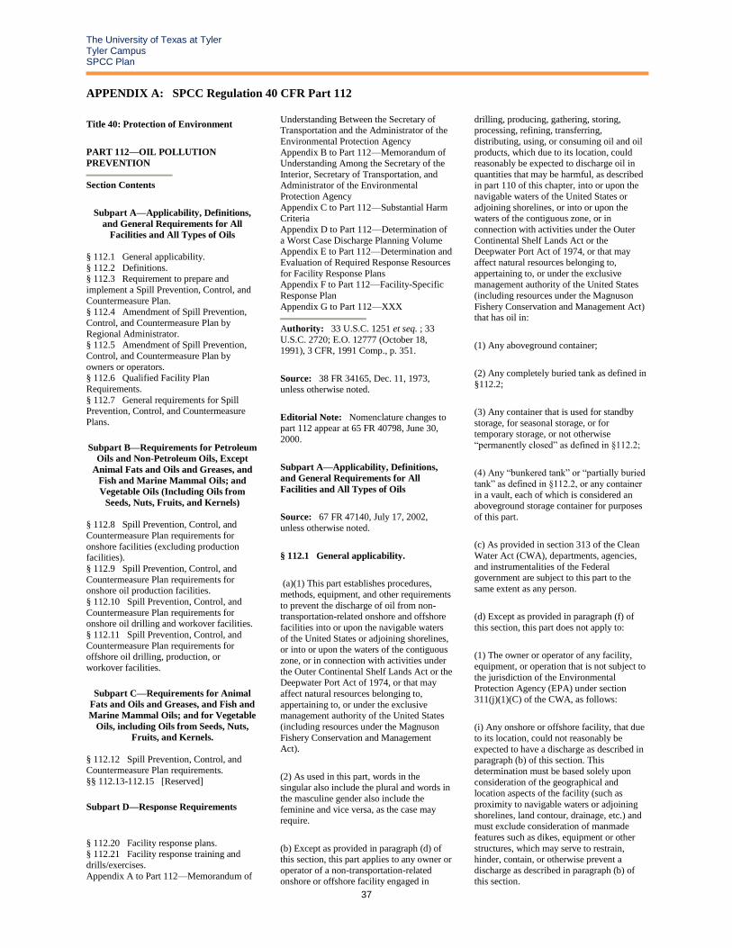
APPENDIX A: SPCC Regulation 40 CFR Part 112
Title 40: Protection of Environment
PART 112—OIL POLLUTION
PREVENTION
Section Contents
Subpart A—Applicability, Definitions,
and General Requirements for All
Facilities and All Types of Oils
§ 112.1 General applicability.
§ 112.2 Definitions. § 112.3 Requirement to prepare and
implement a Spill Prevention, Control, and
Countermeasure Plan. § 112.4 Amendment of Spill Prevention,
Control, and Countermeasure Plan by
Regional Administrator. § 112.5 Amendment of Spill Prevention,
Control, and Countermeasure Plan by
owners or operators. § 112.6 Qualified Facility Plan
Requirements.
§ 112.7 General requirements for Spill Prevention, Control, and Countermeasure
Plans.
Subpart B—Requirements for Petroleum
Oils and Non-Petroleum Oils, Except
Animal Fats and Oils and Greases, and
Fish and Marine Mammal Oils; and
Vegetable Oils (Including Oils from
Seeds, Nuts, Fruits, and Kernels) § 112.8 Spill Prevention, Control, and
Countermeasure Plan requirements for
onshore facilities (excluding production facilities).
§ 112.9 Spill Prevention, Control, and
Countermeasure Plan requirements for onshore oil production facilities.
§ 112.10 Spill Prevention, Control, and
Countermeasure Plan requirements for onshore oil drilling and workover facilities.
§ 112.11 Spill Prevention, Control, and
Countermeasure Plan requirements for offshore oil drilling, production, or
workover facilities.
Subpart C—Requirements for Animal
Fats and Oils and Greases, and Fish and
Marine Mammal Oils; and for Vegetable
Oils, including Oils from Seeds, Nuts,
Fruits, and Kernels.
§ 112.12 Spill Prevention, Control, and Countermeasure Plan requirements.
§§ 112.13-112.15 [Reserved]
Subpart D—Response Requirements
§ 112.20 Facility response plans. § 112.21 Facility response training and
drills/exercises.
Appendix A to Part 112—Memorandum of
Understanding Between the Secretary of Transportation and the Administrator of the
Environmental Protection Agency
Appendix B to Part 112—Memorandum of Understanding Among the Secretary of the
Interior, Secretary of Transportation, and Administrator of the Environmental
Protection Agency
Appendix C to Part 112—Substantial Harm Criteria
Appendix D to Part 112—Determination of
a Worst Case Discharge Planning Volume Appendix E to Part 112—Determination and
Evaluation of Required Response Resources
for Facility Response Plans Appendix F to Part 112—Facility-Specific
Response Plan
Appendix G to Part 112—XXX
Authority: 33 U.S.C. 1251 et seq. ; 33
U.S.C. 2720; E.O. 12777 (October 18, 1991), 3 CFR, 1991 Comp., p. 351.
Source: 38 FR 34165, Dec. 11, 1973, unless otherwise noted.
Editorial Note: Nomenclature changes to part 112 appear at 65 FR 40798, June 30,
2000.
Subpart A—Applicability, Definitions,
and General Requirements for All
Facilities and All Types of Oils
Source: 67 FR 47140, July 17, 2002,
unless otherwise noted.
§ 112.1 General applicability.
(a)(1) This part establishes procedures,
methods, equipment, and other requirements
to prevent the discharge of oil from non-transportation-related onshore and offshore
facilities into or upon the navigable waters
of the United States or adjoining shorelines, or into or upon the waters of the contiguous
zone, or in connection with activities under
the Outer Continental Shelf Lands Act or the
Deepwater Port Act of 1974, or that may
affect natural resources belonging to,
appertaining to, or under the exclusive management authority of the United States
(including resources under the Magnuson
Fishery Conservation and Management Act).
(2) As used in this part, words in the singular also include the plural and words in
the masculine gender also include the
feminine and vice versa, as the case may require.
(b) Except as provided in paragraph (d) of this section, this part applies to any owner or
operator of a non-transportation-related
onshore or offshore facility engaged in
drilling, producing, gathering, storing, processing, refining, transferring,
distributing, using, or consuming oil and oil
products, which due to its location, could reasonably be expected to discharge oil in
quantities that may be harmful, as described in part 110 of this chapter, into or upon the
navigable waters of the United States or
adjoining shorelines, or into or upon the waters of the contiguous zone, or in
connection with activities under the Outer
Continental Shelf Lands Act or the Deepwater Port Act of 1974, or that may
affect natural resources belonging to,
appertaining to, or under the exclusive management authority of the United States
(including resources under the Magnuson
Fishery Conservation and Management Act) that has oil in:
(1) Any aboveground container;
(2) Any completely buried tank as defined in
§112.2;
(3) Any container that is used for standby
storage, for seasonal storage, or for temporary storage, or not otherwise
“permanently closed” as defined in §112.2;
(4) Any “bunkered tank” or “partially buried
tank” as defined in §112.2, or any container
in a vault, each of which is considered an aboveground storage container for purposes
of this part.
(c) As provided in section 313 of the Clean
Water Act (CWA), departments, agencies,
and instrumentalities of the Federal government are subject to this part to the
same extent as any person.
(d) Except as provided in paragraph (f) of
this section, this part does not apply to:
(1) The owner or operator of any facility,
equipment, or operation that is not subject to
the jurisdiction of the Environmental
Protection Agency (EPA) under section
311(j)(1)(C) of the CWA, as follows:
(i) Any onshore or offshore facility, that due
to its location, could not reasonably be
expected to have a discharge as described in paragraph (b) of this section. This
determination must be based solely upon
consideration of the geographical and location aspects of the facility (such as
proximity to navigable waters or adjoining
shorelines, land contour, drainage, etc.) and must exclude consideration of manmade
features such as dikes, equipment or other
structures, which may serve to restrain, hinder, contain, or otherwise prevent a
discharge as described in paragraph (b) of
this section.

The University of Texas at Tyler Tyler Campus SPCC Plan
38
(ii) Any equipment, or operation of a vessel
or transportation-related onshore or offshore
facility which is subject to the authority and
control of the U.S. Department of Transportation, as defined in the
Memorandum of Understanding between the
Secretary of Transportation and the Administrator of EPA, dated November 24,
1971 (Appendix A of this part).
(iii) Any equipment, or operation of a vessel
or onshore or offshore facility which is
subject to the authority and control of the U.S. Department of Transportation or the
U.S. Department of the Interior, as defined
in the Memorandum of Understanding between the Secretary of Transportation, the
Secretary of the Interior, and the
Administrator of EPA, dated November 8, 1993 (Appendix B of this part).
(2) Any facility which, although otherwise subject to the jurisdiction of EPA, meets
both of the following requirements:
(i) The completely buried storage capacity
of the facility is 42,000 gallons or less of oil. For purposes of this exemption, the
completely buried storage capacity of a
facility excludes the capacity of a completely buried tank, as defined in
§112.2, and connected underground piping,
underground ancillary equipment, and containment systems, that is currently
subject to all of the technical requirements
of part 280 of this chapter or all of the technical requirements of a State program
approved under part 281 of this chapter. The
completely buried storage capacity of a facility also excludes the capacity of a
container that is “permanently closed,” as
defined in §112.2.
(ii) The aggregate aboveground storage
capacity of the facility is 1,320 gallons or less of oil. For the purposes of this
exemption, only containers with a capacity
of 55 gallons or greater are counted. The aggregate aboveground storage capacity of a
facility excludes the capacity of a container
that is “permanently closed,” and the capacity of a “motive power container” as
defined in §112.2.
(3) Any offshore oil drilling, production, or
workover facility that is subject to the
notices and regulations of the Minerals Management Service, as specified in the
Memorandum of Understanding between the
Secretary of Transportation, the Secretary of the Interior, and the Administrator of EPA,
dated November 8, 1993 (Appendix B of
this part).
(4) Any completely buried storage tank, as
defined in §112.2, and connected underground piping, underground ancillary
equipment, and containment systems, at any
facility, that is subject to all of the technical
requirements of part 280 of this chapter or a
State program approved under part 281 of this chapter, except that such a tank must be
marked on the facility diagram as provided
in §112.7(a)(3), if the facility is otherwise subject to this part.
(5) Any container with a storage capacity of less than 55 gallons of oil.
(6) Any facility or part thereof used exclusively for wastewater treatment and not
used to satisfy any requirement of this part.
The production, recovery, or recycling of oil is not wastewater treatment for purposes of
this paragraph.
(7) Any “motive power container,” as
defined in §112.2. The transfer of fuel or
other oil into a motive power container at an otherwise regulated facility is not eligible
for this exemption.
(e) This part establishes requirements for the
preparation and implementation of Spill Prevention, Control, and Countermeasure
(SPCC) Plans. SPCC Plans are designed to
complement existing laws, regulations, rules, standards, policies, and procedures
pertaining to safety standards, fire
prevention, and pollution prevention rules. The purpose of an SPCC Plan is to form a
comprehensive Federal/State spill
prevention program that minimizes the potential for discharges. The SPCC Plan
must address all relevant spill prevention,
control, and countermeasures necessary at the specific facility. Compliance with this
part does not in any way relieve the owner
or operator of an onshore or an offshore facility from compliance with other Federal,
State, or local laws.
(f) Notwithstanding paragraph (d) of this
section, the Regional Administrator may
require that the owner or operator of any facility subject to the jurisdiction of EPA
under section 311(j) of the CWA prepare
and implement an SPCC Plan, or any
applicable part, to carry out the purposes of
the CWA.
(1) Following a preliminary determination,
the Regional Administrator must provide a
written notice to the owner or operator stating the reasons why he must prepare an
SPCC Plan, or applicable part. The Regional
Administrator must send such notice to the owner or operator by certified mail or by
personal delivery. If the owner or operator is
a corporation, the Regional Administrator must also mail a copy of such notice to the
registered agent, if any and if known, of the
corporation in the State where the facility is located.
(2) Within 30 days of receipt of such written
notice, the owner or operator may provide
information and data and may consult with
the Agency about the need to prepare an SPCC Plan, or applicable part.
(3) Within 30 days following the time under paragraph (b)(2) of this section within which
the owner or operator may provide
information and data and consult with the Agency about the need to prepare an SPCC
Plan, or applicable part, the Regional
Administrator must make a final determination regarding whether the owner
or operator is required to prepare and
implement an SPCC Plan, or applicable part. The Regional Administrator must send the
final determination to the owner or operator
by certified mail or by personal delivery. If the owner or operator is a corporation, the
Regional Administrator must also mail a
copy of the final determination to the registered agent, if any and if known, of the
corporation in the State where the facility is located.
(4) If the Regional Administrator makes a final determination that an SPCC Plan, or
applicable part, is necessary, the owner or
operator must prepare the Plan, or applicable part, within six months of that final
determination and implement the Plan, or
applicable part, as soon as possible, but not later than one year after the Regional
Administrator has made a final
determination.
(5) The owner or operator may appeal a final
determination made by the Regional Administrator requiring preparation and
implementation of an SPCC Plan, or
applicable part, under this paragraph. The owner or operator must make the appeal to
the Administrator of EPA within 30 days of
receipt of the final determination under paragraph (b)(3) of this section from the
Regional Administrator requiring
preparation and/or implementation of an SPCC Plan, or applicable part. The owner or
operator must send a complete copy of the
appeal to the Regional Administrator at the time he makes the appeal to the
Administrator. The appeal must contain a
clear and concise statement of the issues and points of fact in the case. In the appeal, the
owner or operator may also provide
additional information. The additional information may be from any person. The
Administrator may request additional
information from the owner or operator. The Administrator must render a decision within
60 days of receiving the appeal or additional
information submitted by the owner or operator and must serve the owner or
operator with the decision made in the
appeal in the manner described in paragraph (f)(1) of this section.

The University of Texas at Tyler Tyler Campus SPCC Plan
39
[67 FR 47140, July 17, 2002, as amended at
71 FR 77290, Dec. 26, 2006]
§ 112.2 Definitions.
For the purposes of this part:
Adverse weather means weather conditions
that make it difficult for response equipment
and personnel to clean up or remove spilled oil, and that must be considered when
identifying response systems and equipment
in a response plan for the applicable operating environment. Factors to consider
include significant wave height as specified
in Appendix E to this part (as appropriate), ice conditions, temperatures, weather-related
visibility, and currents within the area in
which the systems or equipment is intended to function.
Alteration means any work on a container involving cutting, burning, welding, or
heating operations that changes the physical
dimensions or configuration of the container.
Animal fat means a non-petroleum oil, fat,
or grease of animal, fish, or marine mammal
origin.
Breakout tank means a container used to
relieve surges in an oil pipeline system or to
receive and store oil transported by a
pipeline for reinjection and continued
transportation by pipeline.
Bulk storage container means any container
used to store oil. These containers are used for purposes including, but not limited to,
the storage of oil prior to use, while being
used, or prior to further distribution in commerce. Oil-filled electrical, operating, or
manufacturing equipment is not a bulk
storage container.
Bunkered tank means a container
constructed or placed in the ground by cutting the earth and re-covering the
container in a manner that breaks the
surrounding natural grade, or that lies above grade, and is covered with earth, sand,
gravel, asphalt, or other material. A
bunkered tank is considered an aboveground storage container for purposes of this part.
Completely buried tank means any container completely below grade and covered with
earth, sand, gravel, asphalt, or other
material. Containers in vaults, bunkered tanks, or partially buried tanks are
considered aboveground storage containers
for purposes of this part.
Complex means a facility possessing a
combination of transportation-related and
non-transportation-related components that
is subject to the jurisdiction of more than one Federal agency under section 311(j) of
the CWA.
Contiguous zone means the zone established
by the United States under Article 24 of the
Convention of the Territorial Sea and Contiguous Zone, that is contiguous to the
territorial sea and that extends nine miles
seaward from the outer limit of the territorial area.
Contract or other approved means means:
(1) A written contractual agreement with an
oil spill removal organization that identifies and ensures the availability of the necessary
personnel and equipment within appropriate
response times; and/or
(2) A written certification by the owner or
operator that the necessary personnel and equipment resources, owned or operated by
the facility owner or operator, are available to respond to a discharge within appropriate
response times; and/or
(3) Active membership in a local or regional
oil spill removal organization that has
identified and ensures adequate access through such membership to necessary
personnel and equipment to respond to a
discharge within appropriate response times in the specified geographic area; and/or
(4) Any other specific arrangement approved by the Regional Administrator
upon request of the owner or operator.
Discharge includes, but is not limited to,
any spilling, leaking, pumping, pouring,
emitting, emptying, or dumping of oil, but excludes discharges in compliance with a
permit under section 402 of the CWA;
discharges resulting from circumstances identified, reviewed, and made a part of the
public record with respect to a permit issued
or modified under section 402 of the CWA, and subject to a condition in such permit; or
continuous or anticipated intermittent
discharges from a point source, identified in a permit or permit application under section
402 of the CWA, that are caused by events
occurring within the scope of relevant operating or treatment systems. For purposes
of this part, the term discharge shall not
include any discharge of oil that is authorized by a permit issued under section
13 of the River and Harbor Act of 1899 (33
U.S.C. 407).
Facility means any mobile or fixed, onshore
or offshore building, structure, installation,
equipment, pipe, or pipeline (other than a
vessel or a public vessel) used in oil well
drilling operations, oil production, oil
refining, oil storage, oil gathering, oil processing, oil transfer, oil distribution, and
waste treatment, or in which oil is used, as
described in Appendix A to this part. The boundaries of a facility depend on several
site-specific factors, including, but not
limited to, the ownership or operation of buildings, structures, and equipment on the
same site and the types of activity at the site.
Farm means a facility on a tract of land
devoted to the production of crops or raising
of animals, including fish, which produced and sold, or normally would have produced
and sold, $1,000 or more of agricultural
products during a year.
Fish and wildlife and sensitive environments
means areas that may be identified by their legal designation or by evaluations of Area
Committees (for planning) or members of the Federal On-Scene Coordinator's spill
response structure (during responses). These
areas may include wetlands, National and State parks, critical habitats for endangered
or threatened species, wilderness and natural
resource areas, marine sanctuaries and estuarine reserves, conservation areas,
preserves, wildlife areas, wildlife refuges,
wild and scenic rivers, recreational areas, national forests, Federal and State lands that
are research national areas, heritage program
areas, land trust areas, and historical and archaeological sites and parks. These areas
may also include unique habitats such as
aquaculture sites and agricultural surface water intakes, bird nesting areas, critical
biological resource areas, designated
migratory routes, and designated seasonal habitats.
Injury means a measurable adverse change, either long- or short-term, in the chemical or
physical quality or the viability of a natural
resource resulting either directly or indirectly from exposure to a discharge, or
exposure to a product of reactions resulting
from a discharge.
Maximum extent practicable means within
the limitations used to determine oil spill planning resources and response times for
on-water recovery, shoreline protection, and
cleanup for worst case discharges from onshore non-transportation-related facilities
in adverse weather. It includes the planned
capability to respond to a worst case discharge in adverse weather, as contained
in a response plan that meets the
requirements in §112.20 or in a specific plan approved by the Regional Administrator.
Mobile refueler means a bulk storage container onboard a vehicle or towed, that is
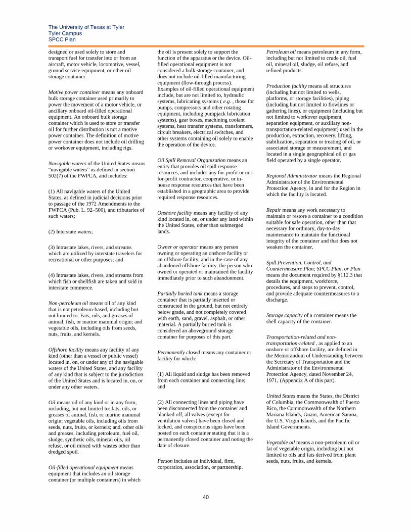
The University of Texas at Tyler Tyler Campus SPCC Plan
40
designed or used solely to store and
transport fuel for transfer into or from an
aircraft, motor vehicle, locomotive, vessel,
ground service equipment, or other oil storage container.
Motive power container means any onboard bulk storage container used primarily to
power the movement of a motor vehicle, or
ancillary onboard oil-filled operational equipment. An onboard bulk storage
container which is used to store or transfer
oil for further distribution is not a motive power container. The definition of motive
power container does not include oil drilling
or workover equipment, including rigs.
Navigable waters of the United States means
“navigable waters” as defined in section 502(7) of the FWPCA, and includes:
(1) All navigable waters of the United States, as defined in judicial decisions prior
to passage of the 1972 Amendments to the
FWPCA (Pub. L. 92–500), and tributaries of such waters;
(2) Interstate waters;
(3) Intrastate lakes, rivers, and streams which are utilized by interstate travelers for
recreational or other purposes; and
(4) Intrastate lakes, rivers, and streams from
which fish or shellfish are taken and sold in
interstate commerce.
Non-petroleum oil means oil of any kind
that is not petroleum-based, including but not limited to: Fats, oils, and greases of
animal, fish, or marine mammal origin; and
vegetable oils, including oils from seeds, nuts, fruits, and kernels.
Offshore facility means any facility of any kind (other than a vessel or public vessel)
located in, on, or under any of the navigable
waters of the United States, and any facility of any kind that is subject to the jurisdiction
of the United States and is located in, on, or
under any other waters.
Oil means oil of any kind or in any form,
including, but not limited to: fats, oils, or greases of animal, fish, or marine mammal
origin; vegetable oils, including oils from
seeds, nuts, fruits, or kernels; and, other oils and greases, including petroleum, fuel oil,
sludge, synthetic oils, mineral oils, oil
refuse, or oil mixed with wastes other than dredged spoil.
Oil-filled operational equipment means equipment that includes an oil storage
container (or multiple containers) in which
the oil is present solely to support the
function of the apparatus or the device. Oil-
filled operational equipment is not
considered a bulk storage container, and does not include oil-filled manufacturing
equipment (flow-through process).
Examples of oil-filled operational equipment include, but are not limited to, hydraulic
systems, lubricating systems ( e.g. , those for
pumps, compressors and other rotating equipment, including pumpjack lubrication
systems), gear boxes, machining coolant
systems, heat transfer systems, transformers, circuit breakers, electrical switches, and
other systems containing oil solely to enable
the operation of the device.
Oil Spill Removal Organization means an
entity that provides oil spill response resources, and includes any for-profit or not-
for-profit contractor, cooperative, or in-
house response resources that have been established in a geographic area to provide
required response resources.
Onshore facility means any facility of any
kind located in, on, or under any land within the United States, other than submerged
lands.
Owner or operator means any person
owning or operating an onshore facility or
an offshore facility, and in the case of any abandoned offshore facility, the person who
owned or operated or maintained the facility
immediately prior to such abandonment.
Partially buried tank means a storage
container that is partially inserted or constructed in the ground, but not entirely
below grade, and not completely covered
with earth, sand, gravel, asphalt, or other material. A partially buried tank is
considered an aboveground storage
container for purposes of this part.
Permanently closed means any container or
facility for which:
(1) All liquid and sludge has been removed
from each container and connecting line;
and
(2) All connecting lines and piping have been disconnected from the container and
blanked off, all valves (except for
ventilation valves) have been closed and locked, and conspicuous signs have been
posted on each container stating that it is a
permanently closed container and noting the date of closure.
Person includes an individual, firm, corporation, association, or partnership.
Petroleum oil means petroleum in any form,
including but not limited to crude oil, fuel
oil, mineral oil, sludge, oil refuse, and
refined products.
Production facility means all structures
(including but not limited to wells, platforms, or storage facilities), piping
(including but not limited to flowlines or
gathering lines), or equipment (including but not limited to workover equipment,
separation equipment, or auxiliary non-
transportation-related equipment) used in the production, extraction, recovery, lifting,
stabilization, separation or treating of oil, or
associated storage or measurement, and located in a single geographical oil or gas
field operated by a single operator.
Regional Administrator means the Regional
Administrator of the Environmental
Protection Agency, in and for the Region in which the facility is located.
Repair means any work necessary to maintain or restore a container to a condition
suitable for safe operation, other than that necessary for ordinary, day-to-day
maintenance to maintain the functional
integrity of the container and that does not weaken the container.
Spill Prevention, Control, and Countermeasure Plan; SPCC Plan, or Plan
means the document required by §112.3 that
details the equipment, workforce, procedures, and steps to prevent, control,
and provide adequate countermeasures to a
discharge.
Storage capacity of a container means the
shell capacity of the container.
Transportation-related and non-
transportation-related , as applied to an onshore or offshore facility, are defined in
the Memorandum of Understanding between
the Secretary of Transportation and the Administrator of the Environmental
Protection Agency, dated November 24,
1971, (Appendix A of this part).
United States means the States, the District
of Columbia, the Commonwealth of Puerto Rico, the Commonwealth of the Northern
Mariana Islands, Guam, American Samoa,
the U.S. Virgin Islands, and the Pacific Island Governments.
Vegetable oil means a non-petroleum oil or fat of vegetable origin, including but not
limited to oils and fats derived from plant
seeds, nuts, fruits, and kernels.

The University of Texas at Tyler Tyler Campus SPCC Plan
41
Vessel means every description of watercraft
or other artificial contrivance used, or
capable of being used, as a means of
transportation on water, other than a public vessel.
Wetlands means those areas that are inundated or saturated by surface or
groundwater at a frequency or duration
sufficient to support, and that under normal circumstances do support, a prevalence of
vegetation typically adapted for life in
saturated soil conditions. Wetlands generally include playa lakes, swamps, marshes, bogs,
and similar areas such as sloughs, prairie
potholes, wet meadows, prairie river overflows, mudflats, and natural ponds.
Worst case discharge for an onshore non-transportation-related facility means the
largest foreseeable discharge in adverse
weather conditions as determined using the worksheets in Appendix D to this part.
[67 FR 47140, July 17, 2002, as amended at 71 FR 77290, Dec. 26, 2006; 73 FR 71943,
Nov. 26, 2008]
§ 112.3 Requirement to prepare and
implement a Spill Prevention, Control,
The owner or operator of an onshore or
offshore facility subject to this section must prepare a Spill Prevention, Control, and
Countermeasure Plan (hereafter “SPCC
Plan” or “Plan),” in writing, and in accordance with §112.7, and any other
applicable section of this part.
(a)(1) If your onshore or offshore facility
was in operation on or before August 16,
2002, you must maintain your Plan, but most amend it, if necessary to ensure
compliance with this part, and implement
the Plan no later than July 1, 2009. If your onshore or offshore facility becomes
operational after August 16, 2002, through
July 1, 2009, and could reasonably be expected to have a discharge as described in
§112.1(b), you must prepare and implement
a Plan on or before July 1, 2009.
(2) If your onshore facility is a farm as
defined in §112.2, the compliance date described in paragraph (a)(1) of this section
is delayed until the effective date of a rule
establishing SPCC requirements specifically for farms or otherwise establishes dates by
which farms must comply with the
provisions of this part.
(b)(1) If you are the owner or operator of an
onshore or offshore facility that becomes operational after July 1, 2009, and could
reasonably be expected to have a discharge
as described in §112.1(b), you must prepare
and implement a Plan before you begin
operations.
(2) If your onshore facility meets the definition of farm in §112.2, the compliance
date described in paragraph (b)(1) of this
section is delayed until the effective date of a rule establishing SPCC requirements
specifically for farms or otherwise
establishes dates by which farms must comply with the provisions of this part.
(c) If you are the owner or operator of an onshore or offshore mobile facility, such as
an onshore drilling or workover rig, barge
mounted offshore drilling or workover rig, or portable fueling facility, you must
prepare, implement, and maintain a facility
Plan as required by this section. You must maintain your Plan, but must amend and
implement it, if necessary to ensure
compliance with this part, on or before July 1, 2009. If your onshore or offshore mobile
facility becomes operational after July 1, 2009, and could reasonably be expected to
have a discharge as described in §112.1(b),
you must prepare and implement a Plan before you begin operations. This provision
does not require that you prepare a new Plan
each time you move the facility to a new site. The Plan may be a general Plan. When
you move the mobile or portable facility,
you must locate and install it using the discharge prevention practices outlined in
the Plan for the facility. The Plan is
applicable only while the facility is in a fixed (non-transportation) operating mode.
(d) Except as provided in §112.6, a licensed Professional Engineer must review and
certify a Plan for it to be effective to satisfy
the requirements of this part.
(1) By means of this certification the
Professional Engineer attests:
(i) That he is familiar with the requirements
of this part;
(ii) That he or his agent has visited and
examined the facility;
(iii) That the Plan has been prepared in
accordance with good engineering practice, including consideration of applicable
industry standards, and with the
requirements of this part;
(iv) That procedures for required inspections
and testing have been established; and
(v) That the Plan is adequate for the facility.
(2) Such certification shall in no way relieve
the owner or operator of a facility of his
duty to prepare and fully implement such
Plan in accordance with the requirements of
this part.
(e) If you are the owner or operator of a
facility for which a Plan is required under
this section, you must:
(1) Maintain a complete copy of the Plan at
the facility if the facility is normally attended at least four hours per day, or at the
nearest field office if the facility is not so
attended, and
(2) Have the Plan available to the Regional
Administrator for on-site review during normal working hours.
(f) Extension of time. (1) The Regional Administrator may authorize an extension of
time for the preparation and full
implementation of a Plan, or any amendment thereto, beyond the time
permitted for the preparation,
implementation, or amendment of a Plan under this part, when he finds that the owner
or operator of a facility subject to this section, cannot fully comply with the
requirements as a result of either
nonavailability of qualified personnel, or delays in construction or equipment delivery
beyond the control and without the fault of
such owner or operator or his agents or employees.
(2) If you are an owner or operator seeking an extension of time under paragraph (f)(1)
of this section, you may submit a written
extension request to the Regional Administrator. Your request must include:
(i) A full explanation of the cause for any such delay and the specific aspects of the
Plan affected by the delay;
(ii) A full discussion of actions being taken
or contemplated to minimize or mitigate
such delay; and
(iii) A proposed time schedule for the
implementation of any corrective actions being taken or contemplated, including
interim dates for completion of tests or
studies, installation and operation of any necessary equipment, or other preventive
measures. In addition you may present
additional oral or written statements in support of your extension request.
(3) The submission of a written extension request under paragraph (f)(2) of this section
does not relieve you of your obligation to
comply with the requirements of this part. The Regional Administrator may request a
copy of your Plan to evaluate the extension

The University of Texas at Tyler Tyler Campus SPCC Plan
42
request. When the Regional Administrator
authorizes an extension of time for particular
equipment or other specific aspects of the
Plan, such extension does not affect your obligation to comply with the requirements
related to other equipment or other specific
aspects of the Plan for which the Regional Administrator has not expressly authorized
an extension.
(g) Qualified Facilities. The owner or
operator of a qualified facility as defined in
this subparagraph may self-certify his or her facility's Plan, as provided in §112.6. A
qualified facility is one that:
(1) Has an aggregate aboveground storage
capacity of 10,000 gallons or less; and
(2) Has had no single discharge as described
in §112.1(b) exceeding 1,000 U.S. gallons or
no two discharges as described in §112.1(b) each exceeding 42 U.S. gallons within any
twelve month period in the three years prior
to the SPCC Plan self-certification date, or since becoming subject to this part if the
facility has been in operation for less than three years (other than discharges as
described in §112.1(b) that are the result of
natural disasters, acts of war, or terrorism).
[67 FR 47140, July 17, 2002, as amended at
68 FR 1351, Jan. 9, 2003; 68 FR 18894, Apr. 17, 2003; 69 FR 48798, Aug. 11, 2004;
71 FR 8466, Feb. 17, 2006; 71 FR 77290,
Dec. 26, 2006; 72 FR 27447, May 16, 2007]
§ 112.4 Amendment of Spill Prevention,
Control, and Countermeasure Plan by
Regional Administrator.
If you are the owner or operator of a facility subject to this part, you must:
(a) Notwithstanding compliance with §112.3, whenever your facility has
discharged more than 1,000 U.S. gallons of
oil in a single discharge as described in §112.1(b), or discharged more than 42 U.S.
gallons of oil in each of two discharges as
described in §112.1(b), occurring within any twelve month period, submit the following
information to the Regional Administrator
within 60 days from the time the facility becomes subject to this section:
(1) Name of the facility;
(2) Your name;
(3) Location of the facility;
(4) Maximum storage or handling capacity of the facility and normal daily throughput;
(5) Corrective action and countermeasures
you have taken, including a description of
equipment repairs and replacements;
(6) An adequate description of the facility,
including maps, flow diagrams, and
topographical maps, as necessary;
(7) The cause of such discharge as described
in §112.1(b), including a failure analysis of the system or subsystem in which the failure
occurred;
(8) Additional preventive measures you
have taken or contemplated to minimize the
possibility of recurrence; and
(9) Such other information as the Regional
Administrator may reasonably require pertinent to the Plan or discharge.
(b) Take no action under this section until it applies to your facility. This section does not
apply until the expiration of the time
permitted for the initial preparation and implementation of the Plan under §112.3,
but not including any amendments to the Plan.
(c) Send to the appropriate agency or agencies in charge of oil pollution control
activities in the State in which the facility is
located a complete copy of all information
you provided to the Regional Administrator
under paragraph (a) of this section. Upon
receipt of the information such State agency or agencies may conduct a review and make
recommendations to the Regional
Administrator as to further procedures, methods, equipment, and other requirements
necessary to prevent and to contain
discharges from your facility.
(d) Amend your Plan, if after review by the
Regional Administrator of the information you submit under paragraph (a) of this
section, or submission of information to
EPA by the State agency under paragraph (c) of this section, or after on-site review of
your Plan, the Regional Administrator
requires that you do so. The Regional Administrator may require you to amend
your Plan if he finds that it does not meet the
requirements of this part or that amendment is necessary to prevent and contain
discharges from your facility.
(e) Act in accordance with this paragraph
when the Regional Administrator proposes
by certified mail or by personal delivery that you amend your SPCC Plan. If the owner or
operator is a corporation, he must also notify
by mail the registered agent of such corporation, if any and if known, in the State
in which the facility is located. The Regional
Administrator must specify the terms of
such proposed amendment. Within 30 days
from receipt of such notice, you may submit
written information, views, and arguments
on the proposed amendment. After considering all relevant material presented,
the Regional Administrator must either
notify you of any amendment required or rescind the notice. You must amend your
Plan as required within 30 days after such
notice, unless the Regional Administrator, for good cause, specifies another effective
date. You must implement the amended Plan
as soon as possible, but not later than six months after you amend your Plan, unless
the Regional Administrator specifies another
date.
(f) If you appeal a decision made by the
Regional Administrator requiring an amendment to an SPCC Plan, send the
appeal to the EPA Administrator in writing
within 30 days of receipt of the notice from the Regional Administrator requiring the
amendment under paragraph (e) of this section. You must send a complete copy of
the appeal to the Regional Administrator at
the time you make the appeal. The appeal must contain a clear and concise statement
of the issues and points of fact in the case. It
may also contain additional information from you, or from any other person. The
EPA Administrator may request additional
information from you, or from any other person. The EPA Administrator must render
a decision within 60 days of receiving the
appeal and must notify you of his decision.
§ 112.5 Amendment of Spill Prevention,
Control, and Countermeasure Plan by
owners or operators.
If you are the owner or operator of a facility subject to this part, you must:
(a) Amend the SPCC Plan for your facility in accordance with the general requirements
in §112.7, and with any specific section of
this part applicable to your facility, when there is a change in the facility design,
construction, operation, or maintenance that
materially affects its potential for a discharge as described in §112.1(b).
Examples of changes that may require
amendment of the Plan include, but are not limited to: commissioning or
decommissioning containers; replacement,
reconstruction, or movement of containers; reconstruction, replacement, or installation
of piping systems; construction or
demolition that might alter secondary containment structures; changes of product
or service; or revision of standard operation
or maintenance procedures at a facility. An amendment made under this section must be
prepared within six months, and
implemented as soon as possible, but not later than six months following preparation
of the amendment.

The University of Texas at Tyler Tyler Campus SPCC Plan
43
(b) Notwithstanding compliance with
paragraph (a) of this section, complete a
review and evaluation of the SPCC Plan at
least once every five years from the date your facility becomes subject to this part; or,
if your facility was in operation on or before
August 16, 2002, five years from the date your last review was required under this
part. As a result of this review and
evaluation, you must amend your SPCC Plan within six months of the review to
include more effective prevention and
control technology if the technology has been field-proven at the time of the review
and will significantly reduce the likelihood
of a discharge as described in §112.1(b) from the facility. You must implement any
amendment as soon as possible, but not later
than six months following preparation of any amendment. You must document your
completion of the review and evaluation,
and must sign a statement as to whether you will amend the Plan, either at the beginning
or end of the Plan or in a log or an appendix to the Plan. The following words will
suffice, “I have completed review and
evaluation of the SPCC Plan for (name of facility) on (date), and will (will not) amend
the Plan as a result.”
(c) Except as provided in §112.6, have a
Professional Engineer certify any technical
amendments to your Plan in accordance with §112.3(d).
[67 FR 47140, July 17, 2002, as amended at 71 FR 77291, Dec. 26, 2006]
§ 112.6 Qualified Facility Plan
Requirements.
(a) Preparation and Self-certification of Plan. If you are the owner or operator of a
facility that meets the qualified facility
qualification criteria in §112.3(g), you may choose to self-certify your Plan. You must
certify in the Plan that:
(1) You are familiar with the requirements
of this part;
(2) You have visited and examined the
facility;
(3) The Plan has been prepared in
accordance with accepted and sound
industry practices and standards, and with the requirements of this part;
(4) Procedures for required inspections and testing have been established;
(5) The Plan is being fully implemented;
(6) The facility meets the qualification
criteria set forth under §112.3(g);
(7) The Plan does not deviate from any requirement of this part as allowed by
§§112.7(a)(2) and 112.7(d), except as
provided in paragraph (c) of this section; and
(8) The Plan and individual(s) responsible for implementing the Plan have the full
approval of management and the facility
owner or operator has committed the necessary resources to fully implement the
Plan.
(b) Self-certification of Technical
Amendments. If you self-certify your Plan
pursuant to paragraph (a) of this section, you must certify any technical amendments to
your Plan in accordance with paragraph (a)
of this section when there is a change in the facility design, construction, operation, or
maintenance that affects its potential for a
discharge as described in §112.1(b) except:
(1) If a Professional Engineer certified a portion of your Plan in accordance with
paragraph (d) of this section, and the
technical amendment affects this portion of the Plan, you must have the amended
provisions of your Plan certified by a
Professional Engineer in accordance with §112.6(d)(2).
(2) If the change is such that the facility no longer meets the qualifying criteria in
§112.3(g) because it exceeds 10,000 gallons
in aggregate aboveground storage capacity, you must prepare a Plan in accordance with
the general Plan requirements in §112.7 and
the applicable requirements in subparts B and C, including having the Plan certified by
a Professional Engineer as required under
§112.3(d).
(c) Applicable Requirements. Except as
provided in this subparagraph, your self-certified SPCC Plan must comply with
§112.7 and the applicable requirements in
subparts B and C of this part:
(1) Environmental Equivalence. Your Plan
may not include alternate methods which provide environmental equivalence pursuant
to §112.7(a)(2), unless each alternate
method has been reviewed and certified in writing by a Professional Engineer, as
provided in paragraph (d) of this section.
(2) Impracticability. Your Plan may not
include any determinations that secondary
containment is impracticable and provisions in lieu of secondary containment pursuant to
§112.7(d), unless each such determination
and alternative provision has been reviewed
and certified in writing by a Professional
Engineer, as provided in paragraph (d) of
this section.
(3) Security (excluding oil production
facilities). You must either:
(i) Comply with the requirements under
§112.7(g); or
(ii) Describe in your Plan how you secure
and control access to the oil handling,
processing and storage areas; secure master flow and drain valves; prevent unauthorized
access to starter controls on oil pumps;
secure out-of-service and loading/unloading connections of oil pipelines; address the
appropriateness of security lighting to both
prevent acts of vandalism and assist in the discovery of oil discharges.
(4) Bulk Storage Container Inspections. You must either:
(i) Comply with the requirements under §112.8(c)(6) or §112.12(c)(6), as applicable;
or
(ii) Test/inspect each aboveground container
for integrity on a regular schedule and whenever material repairs are made. You
must determine, in accordance with industry
standards, the appropriate qualifications for
personnel performing tests and inspections,
the frequency and type of testing and
inspections which take into account container size, configuration, and design
(such as containers that are: shop built, skid-
mounted, elevated, equipped with a liner, double walled, or partially buried).
Examples of these integrity tests include, but
are not limited to: visual inspection, hydrostatic testing, radiographic testing,
ultrasonic testing, acoustic emissions testing,
or other systems of non-destructive testing. You must keep comparison records and you
must also inspect the container's supports
and foundations. In addition, you must frequently inspect the outside of the
container for signs of deterioration,
discharges, or accumulation of oil inside
diked areas. Records of inspections and tests
kept under usual and customary business
practices satisfy the recordkeeping requirements of this paragraph.
(d) Professional Engineer Certification of Portions of a Qualified Facility's Self-
certified Plan. As described in paragraph (c)
of this section, the facility owner or operator may not self-certify alternative measures
allowed under §112.7(a)(2) or (d), that are
included in the facility's Plan. Such measures must be reviewed and certified, in
writing, by a licensed Professional Engineer
as follows:
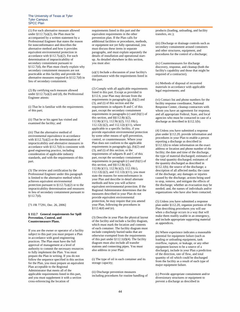
The University of Texas at Tyler Tyler Campus SPCC Plan
44
(1) For each alternative measure allowed
under §112.7(a)(2), the Plan must be
accompanied by a written statement by a
Professional Engineer that states the reason for nonconformance and describes the
alternative method and how it provides
equivalent environmental protection in accordance with §112.7(a)(2). For each
determination of impracticability of
secondary containment pursuant to §112.7(d), the Plan must clearly explain why
secondary containment measures are not
practicable at this facility and provide the alternative measures required in §112.7(d) in
lieu of secondary containment.
(2) By certifying each measure allowed
under §112.7(a)(2) and (d), the Professional
Engineer attests:
(i) That he is familiar with the requirements
of this part;
(ii) That he or his agent has visited and
examined the facility; and
(iii) That the alternative method of environmental equivalence in accordance
with §112.7(a)(2) or the determination of
impracticability and alternative measures in accordance with §112.7(d) is consistent with
good engineering practice, including
consideration of applicable industry standards, and with the requirements of this
part.
(3) The review and certification by the
Professional Engineer under this paragraph
is limited to the alternative method which achieves equivalent environmental
protection pursuant to §112.7(a)(2) or to the
impracticability determination and measures in lieu of secondary containment pursuant to
§112.7(d).
[71 FR 77291, Dec. 26, 2006]
§ 112.7 General requirements for Spill
Prevention, Control, and
Countermeasure Plans.
If you are the owner or operator of a facility
subject to this part you must prepare a Plan
in accordance with good engineering practices. The Plan must have the full
approval of management at a level of
authority to commit the necessary resources to fully implement the Plan. You must
prepare the Plan in writing. If you do not
follow the sequence specified in this section for the Plan, you must prepare an equivalent
Plan acceptable to the Regional
Administrator that meets all of the applicable requirements listed in this part,
and you must supplement it with a section
cross-referencing the location of
requirements listed in this part and the
equivalent requirements in the other
prevention plan. If the Plan calls for
additional facilities or procedures, methods, or equipment not yet fully operational, you
must discuss these items in separate
paragraphs, and must explain separately the details of installation and operational start-
up. As detailed elsewhere in this section,
you must also:
(a)(1) Include a discussion of your facility's
conformance with the requirements listed in this part.
(2) Comply with all applicable requirements listed in this part. Except as provided in
§112.6, your Plan may deviate from the
requirements in paragraphs (g), (h)(2) and (3), and (i) of this section and the
requirements in subparts B and C of this
part, except the secondary containment requirements in paragraphs (c) and (h)(1) of
this section, and §§112.8(c)(2), 112.8(c)(11), 112.9(c)(2), 112.10(c),
112.12(c)(2), and 112.12(c)(11), where
applicable to a specific facility, if you provide equivalent environmental protection
by some other means of spill prevention,
control, or countermeasure. Where your Plan does not conform to the applicable
requirements in paragraphs (g), (h)(2) and
(3), and (i) of this section, or the requirements of subparts B and C of this
part, except the secondary containment
requirements in paragraph (c) and (h)(1) of this section, and §§112.8(c)(2),
112.8(c)(11), 112.9(c)(2), 112.10(c),
112.12(c)(2), and 112.12(c)(11), you must state the reasons for nonconformance in
your Plan and describe in detail alternate
methods and how you will achieve equivalent environmental protection. If the
Regional Administrator determines that the
measures described in your Plan do not provide equivalent environmental
protection, he may require that you amend
your Plan, following the procedures in §112.4(d) and (e).
(3) Describe in your Plan the physical layout of the facility and include a facility diagram,
which must mark the location and contents
of each container. The facility diagram must include completely buried tanks that are
otherwise exempted from the requirements
of this part under §112.1(d)(4). The facility diagram must also include all transfer
stations and connecting pipes. You must
also address in your Plan:
(i) The type of oil in each container and its
storage capacity;
(ii) Discharge prevention measures
including procedures for routine handling of
products (loading, unloading, and facility
transfers, etc.);
(iii) Discharge or drainage controls such as secondary containment around containers
and other structures, equipment, and
procedures for the control of a discharge;
(iv) Countermeasures for discharge
discovery, response, and cleanup (both the facility's capability and those that might be
required of a contractor);
(v) Methods of disposal of recovered
materials in accordance with applicable
legal requirements; and
(vi) Contact list and phone numbers for the
facility response coordinator, National Response Center, cleanup contractors with
whom you have an agreement for response,
and all appropriate Federal, State, and local agencies who must be contacted in case of a
discharge as described in §112.1(b).
(4) Unless you have submitted a response
plan under §112.20, provide information and procedures in your Plan to enable a person
reporting a discharge as described in
§112.1(b) to relate information on the exact address or location and phone number of the
facility; the date and time of the discharge,
the type of material discharged; estimates of the total quantity discharged; estimates of
the quantity discharged as described in
§112.1(b); the source of the discharge; a description of all affected media; the cause
of the discharge; any damages or injuries
caused by the discharge; actions being used to stop, remove, and mitigate the effects of
the discharge; whether an evacuation may be
needed; and, the names of individuals and/or organizations who have also been contacted.
(5) Unless you have submitted a response plan under §112.20, organize portions of the
Plan describing procedures you will use
when a discharge occurs in a way that will make them readily usable in an emergency,
and include appropriate supporting material
as appendices.
(b) Where experience indicates a reasonable
potential for equipment failure (such as loading or unloading equipment, tank
overflow, rupture, or leakage, or any other
equipment known to be a source of a discharge), include in your Plan a prediction
of the direction, rate of flow, and total
quantity of oil which could be discharged from the facility as a result of each type of
major equipment failure.
(c) Provide appropriate containment and/or
diversionary structures or equipment to
prevent a discharge as described in

The University of Texas at Tyler Tyler Campus SPCC Plan
45
§112.1(b), except as provided in paragraph
(k) of this section for qualified oil-filled
operational equipment. The entire
containment system, including walls and floor, must be capable of containing oil and
must be constructed so that any discharge
from a primary containment system, such as a tank or pipe, will not escape the
containment system before cleanup occurs.
At a minimum, you must use one of the following prevention systems or its
equivalent:
(1) For onshore facilities:
(i) Dikes, berms, or retaining walls sufficiently impervious to contain oil;
(ii) Curbing;
(iii) Culverting, gutters, or other drainage
systems;
(iv) Weirs, booms, or other barriers;
(v) Spill diversion ponds;
(vi) Retention ponds; or
(vii) Sorbent materials.
(2) For offshore facilities:
(i) Curbing or drip pans; or
(ii) Sumps and collection systems.
(d) Provided your Plan is certified by a
licensed Professional Engineer under §112.3(d), or, in the case of a qualified
facility that meets the criteria in §112.3(g),
the relevant sections of your Plan are certified by a licensed Professional Engineer
under §112.6(d), if you determine that the
installation of any of the structures or pieces of equipment listed in paragraphs (c) and
(h)(1) of this section, and §§112.8(c)(2),
112.8(c)(11), 112.9(c)(2), 112.10(c),
112.12(c)(2), and 112.12(c)(11) to prevent a
discharge as described in §112.1(b) from
any onshore or offshore facility is not practicable, you must clearly explain in your
Plan why such measures are not practicable;
for bulk storage containers, conduct both periodic integrity testing of the containers
and periodic integrity and leak testing of the
valves and piping; and, unless you have submitted a response plan under §112.20,
provide in your Plan the following:
(1) An oil spill contingency plan following
the provisions of part 109 of this chapter.
(2) A written commitment of manpower,
equipment, and materials required to
expeditiously control and remove any
quantity of oil discharged that may be harmful.
(e) Inspections, tests, and records. Conduct inspections and tests required by this part in
accordance with written procedures that you
or the certifying engineer develop for the facility. You must keep these written
procedures and a record of the inspections
and tests, signed by the appropriate supervisor or inspector, with the SPCC Plan
for a period of three years. Records of
inspections and tests kept under usual and customary business practices will suffice for
purposes of this paragraph.
(f) Personnel, training, and discharge
prevention procedures. (1) At a minimum,
train your oil-handling personnel in the operation and maintenance of equipment to
prevent discharges; discharge procedure protocols; applicable pollution control laws,
rules, and regulations; general facility
operations; and, the contents of the facility SPCC Plan.
(2) Designate a person at each applicable facility who is accountable for discharge
prevention and who reports to facility
management.
(3) Schedule and conduct discharge
prevention briefings for your oil-handling personnel at least once a year to assure
adequate understanding of the SPCC Plan
for that facility. Such briefings must highlight and describe known discharges as
described in §112.1(b) or failures,
malfunctioning components, and any recently developed precautionary measures.
(g) Security (excluding oil production facilities). (1) Fully fence each facility
handling, processing, or storing oil, and lock
and/or guard entrance gates when the facility is not in production or is unattended.
(2) Ensure that the master flow and drain
valves and any other valves permitting direct
outward flow of the container's contents to
the surface have adequate security measures so that they remain in the closed position
when in non-operating or non-standby
status.
(3) Lock the starter control on each oil pump
in the “off” position and locate it at a site accessible only to authorized personnel
when the pump is in a non-operating or non-
standby status.
(4) Securely cap or blank-flange the
loading/unloading connections of oil
pipelines or facility piping when not in
service or when in standby service for an
extended time. This security practice also
applies to piping that is emptied of liquid content either by draining or by inert gas
pressure.
(5) Provide facility lighting commensurate
with the type and location of the facility that
will assist in the:
(i) Discovery of discharges occurring during
hours of darkness, both by operating personnel, if present, and by non-operating
personnel (the general public, local police,
etc.); and
(ii) Prevention of discharges occurring
through acts of vandalism.
(h) Facility tank car and tank truck
loading/unloading rack (excluding offshore facilities). (1) Where loading/unloading area
drainage does not flow into a catchment
basin or treatment facility designed to handle discharges, use a quick drainage
system for tank car or tank truck loading and unloading areas. You must design any
containment system to hold at least the
maximum capacity of any single compartment of a tank car or tank truck
loaded or unloaded at the facility.
(2) Provide an interlocked warning light or
physical barrier system, warning signs,
wheel chocks, or vehicle break interlock system in loading/unloading areas to prevent
vehicles from departing before complete
disconnection of flexible or fixed oil transfer lines.
(3) Prior to filling and departure of any tank car or tank truck, closely inspect for
discharges the lowermost drain and all
outlets of such vehicles, and if necessary, ensure that they are tightened, adjusted, or
replaced to prevent liquid discharge while in
transit.
(i) If a field-constructed aboveground
container undergoes a repair, alteration, reconstruction, or a change in service that
might affect the risk of a discharge or failure
due to brittle fracture or other catastrophe, or has discharged oil or failed due to brittle
fracture failure or other catastrophe, evaluate
the container for risk of discharge or failure due to brittle fracture or other catastrophe,
and as necessary, take appropriate action.
(j) In addition to the minimal prevention
standards listed under this section, include in
your Plan a complete discussion of conformance with the applicable
requirements and other effective discharge
prevention and containment procedures

The University of Texas at Tyler Tyler Campus SPCC Plan
46
listed in this part or any applicable more
stringent State rules, regulations, and
guidelines.
(k) Qualified Oil-filled Operational
Equipment. The owner or operator of a
facility with oil-filled operational equipment that meets the qualification criteria in
paragraph (k)(1) of this sub-section may
choose to implement for this qualified oil-filled operational equipment the alternate
requirements as described in paragraph
(k)(2) of this sub-section in lieu of general secondary containment required in
paragraph (c) of this section.
(1) Qualification Criteria—Reportable
Discharge History: The owner or operator
of a facility that has had no single discharge as described in §112.1(b) from any oil-filled
operational equipment exceeding 1,000 U.S.
gallons or no two discharges as described in §112.1(b) from any oil-filled operational
equipment each exceeding 42 U.S. gallons within any twelve month period in the three
years prior to the SPCC Plan certification
date, or since becoming subject to this part if the facility has been in operation for less
than three years (other than oil discharges as
described in §112.1(b) that are the result of natural disasters, acts of war or terrorism);
and
(2) Alternative Requirements to General
Secondary Containment. If secondary
containment is not provided for qualified oil-filled operational equipment pursuant to
paragraph (c) of this section, the owner or
operator of a facility with qualified oil-filled operational equipment must:
(i) Establish and document the facility procedures for inspections or a monitoring
program to detect equipment failure and/or a
discharge; and
(ii) Unless you have submitted a response
plan under §112.20, provide in your Plan the following:
(A) An oil spill contingency plan following
the provisions of part 109 of this chapter.
(B) A written commitment of manpower, equipment, and materials required to
expeditiously control and remove any
quantity of oil discharged that may be harmful.
[67 FR 47140, July 17, 2002, as amended at 71 FR 77292, Dec. 26, 2006]
Subpart B—Requirements for Petroleum
Oils and Non-Petroleum Oils, Except
Animal Fats and Oils and Greases, and
Fish and Marine Mammal Oils; and
Vegetable Oils (Including Oils from
Seeds, Nuts, Fruits, and Kernels)
Source: 67 FR 47146, July 17, 2002,
unless otherwise noted.
§ 112.8 Spill Prevention, Control, and
Countermeasure Plan requirements for
onshore facilities (excluding production
facilities).
If you are the owner or operator of an onshore facility (excluding a production
facility), you must:
(a) Meet the general requirements for the
Plan listed under §112.7, and the specific
discharge prevention and containment procedures listed in this section.
(b) Facility drainage. (1) Restrain drainage from diked storage areas by valves to
prevent a discharge into the drainage system
or facility effluent treatment system, except where facility systems are designed to
control such discharge. You may empty diked areas by pumps or ejectors; however,
you must manually activate these pumps or
ejectors and must inspect the condition of the accumulation before starting, to ensure
no oil will be discharged.
(2) Use valves of manual, open-and-closed
design, for the drainage of diked areas. You
may not use flapper-type drain valves to drain diked areas. If your facility drainage
drains directly into a watercourse and not
into an on-site wastewater treatment plant, you must inspect and may drain
uncontaminated retained stormwater, as
provided in paragraphs (c)(3)(ii), (iii), and (iv) of this section.
(3) Design facility drainage systems from undiked areas with a potential for a
discharge (such as where piping is located
outside containment walls or where tank truck discharges may occur outside the
loading area) to flow into ponds, lagoons, or
catchment basins designed to retain oil or return it to the facility. You must not locate
catchment basins in areas subject to periodic
flooding.
(4) If facility drainage is not engineered as
in paragraph (b)(3) of this section, equip the final discharge of all ditches inside the
facility with a diversion system that would,
in the event of an uncontrolled discharge, retain oil in the facility.
(5) Where drainage waters are treated in more than one treatment unit and such
treatment is continuous, and pump transfer
is needed, provide two “lift” pumps and
permanently install at least one of the
pumps. Whatever techniques you use, you
must engineer facility drainage systems to prevent a discharge as described in
§112.1(b) in case there is an equipment
failure or human error at the facility.
(c) Bulk storage containers. (1) Not use a
container for the storage of oil unless its material and construction are compatible
with the material stored and conditions of
storage such as pressure and temperature.
(2) Construct all bulk storage tank
installations (except mobile refuelers) so that you provide a secondary means of
containment for the entire capacity of the
largest single container and sufficient freeboard to contain precipitation. You must
ensure that diked areas are sufficiently
impervious to contain discharged oil. Dikes, containment curbs, and pits are commonly
employed for this purpose. You may also use an alternative system consisting of a
drainage trench enclosure that must be
arranged so that any discharge will terminate and be safely confined in a facility
catchment basin or holding pond.
(3) Not allow drainage of uncontaminated
rainwater from the diked area into a storm
drain or discharge of an effluent into an open watercourse, lake, or pond, bypassing
the facility treatment system unless you:
(i) Normally keep the bypass valve sealed
closed.
(ii) Inspect the retained rainwater to ensure
that its presence will not cause a discharge
as described in §112.1(b).
(iii) Open the bypass valve and reseal it
following drainage under responsible supervision; and
(iv) Keep adequate records of such events, for example, any records required under
permits issued in accordance with
§§122.41(j)(2) and 122.41(m)(3) of this chapter.
(4) Protect any completely buried metallic storage tank installed on or after January 10,
1974 from corrosion by coatings or cathodic
protection compatible with local soil conditions. You must regularly leak test
such completely buried metallic storage
tanks.
(5) Not use partially buried or bunkered
metallic tanks for the storage of oil, unless you protect the buried section of the tank
from corrosion. You must protect partially
The University of Texas at Tyler Tyler Campus SPCC Plan
47
buried and bunkered tanks from corrosion
by coatings or cathodic protection
compatible with local soil conditions.
(6) Test each aboveground container for
integrity on a regular schedule, and
whenever you make material repairs. The frequency of and type of testing must take
into account container size and design (such
as floating roof, skid-mounted, elevated, or partially buried). You must combine visual
inspection with another testing technique
such as hydrostatic testing, radiographic testing, ultrasonic testing, acoustic emissions
testing, or another system of non-destructive
shell testing. You must keep comparison records and you must also inspect the
container's supports and foundations. In
addition, you must frequently inspect the outside of the container for signs of
deterioration, discharges, or accumulation of
oil inside diked areas. Records of inspections and tests kept under usual and
customary business practices will suffice for purposes of this paragraph.
(7) Control leakage through defective internal heating coils by monitoring the
steam return and exhaust lines for
contamination from internal heating coils that discharge into an open watercourse, or
pass the steam return or exhaust lines
through a settling tank, skimmer, or other separation or retention system.
(8) Engineer or update each container installation in accordance with good
engineering practice to avoid discharges.
You must provide at least one of the following devices:
(i) High liquid level alarms with an audible or visual signal at a constantly attended
operation or surveillance station. In smaller
facilities an audible air vent may suffice.
(ii) High liquid level pump cutoff devices
set to stop flow at a predetermined container content level.
(iii) Direct audible or code signal
communication between the container
gauger and the pumping station.
(iv) A fast response system for determining
the liquid level of each bulk storage
container such as digital computers, telepulse, or direct vision gauges. If you use
this alternative, a person must be present to
monitor gauges and the overall filling of bulk storage containers.
(v) You must regularly test liquid level sensing devices to ensure proper operation.
(9) Observe effluent treatment facilities
frequently enough to detect possible system
upsets that could cause a discharge as
described in §112.1(b).
(10) Promptly correct visible discharges
which result in a loss of oil from the container, including but not limited to
seams, gaskets, piping, pumps, valves,
rivets, and bolts. You must promptly remove any accumulations of oil in diked areas.
(11) Position or locate mobile or portable oil storage containers to prevent a discharge as
described in §112.1(b). Except for mobile
refuelers, you must furnish a secondary means of containment, such as a dike or
catchment basin, sufficient to contain the
capacity of the largest single compartment or container with sufficient freeboard to
contain precipitation.
(d) Facility transfer operations, pumping,
and facility process. (1) Provide buried
piping that is installed or replaced on or after August 16, 2002, with a protective wrapping
and coating. You must also cathodically protect such buried piping installations or
otherwise satisfy the corrosion protection
standards for piping in part 280 of this chapter or a State program approved under
part 281 of this chapter. If a section of
buried line is exposed for any reason, you must carefully inspect it for deterioration. If
you find corrosion damage, you must
undertake additional examination and corrective action as indicated by the
magnitude of the damage.
(2) Cap or blank-flange the terminal
connection at the transfer point and mark it
as to origin when piping is not in service or is in standby service for an extended time.
(3) Properly design pipe supports to minimize abrasion and corrosion and allow
for expansion and contraction.
(4) Regularly inspect all aboveground
valves, piping, and appurtenances. During
the inspection you must assess the general
condition of items, such as flange joints,
expansion joints, valve glands and bodies,
catch pans, pipeline supports, locking of valves, and metal surfaces. You must also
conduct integrity and leak testing of buried
piping at the time of installation, modification, construction, relocation, or
replacement.
(5) Warn all vehicles entering the facility to
be sure that no vehicle will endanger
aboveground piping or other oil transfer operations.
[67 FR 47146, July 17, 2002, as amended at
71 FR 77293, Dec. 26, 2006]
§ 112.9 Spill Prevention, Control, and
Countermeasure Plan requirements for
onshore oil production facilities.
If you are the owner or operator of an
onshore production facility, you must:
(a) Meet the general requirements for the
Plan listed under §112.7, and the specific
discharge prevention and containment procedures listed under this section.
(b) Oil production facility drainage. (1) At
tank batteries and separation and treating
areas where there is a reasonable possibility
of a discharge as described in §112.1(b), close and seal at all times drains of dikes or
drains of equivalent measures required
under §112.7(c)(1), except when draining uncontaminated rainwater. Prior to drainage,
you must inspect the diked area and take
action as provided in §112.8(c)(3)(ii), (iii), and (iv). You must remove accumulated oil
on the rainwater and return it to storage or dispose of it in accordance with legally
approved methods.
(2) Inspect at regularly scheduled intervals
field drainage systems (such as drainage
ditches or road ditches), and oil traps, sumps, or skimmers, for an accumulation of
oil that may have resulted from any small
discharge. You must promptly remove any accumulations of oil.
(c) Oil production facility bulk storage containers. (1) Not use a container for the
storage of oil unless its material and
construction are compatible with the material stored and the conditions of
storage.
(2) Provide all tank battery, separation, and
treating facility installations with a
secondary means of containment for the entire capacity of the largest single container
and sufficient freeboard to contain
precipitation. You must safely confine drainage from undiked areas in a catchment
basin or holding pond.
(3) Periodically and upon a regular schedule
visually inspect each container of oil for
deterioration and maintenance needs, including the foundation and support of each
container that is on or above the surface of
the ground.
(4) Engineer or update new and old tank
battery installations in accordance with good engineering practice to prevent discharges.

The University of Texas at Tyler Tyler Campus SPCC Plan
48
You must provide at least one of the
following:
(i) Container capacity adequate to assure that a container will not overfill if a
pumper/gauger is delayed in making
regularly scheduled rounds.
(ii) Overflow equalizing lines between
containers so that a full container can overflow to an adjacent container.
(iii) Vacuum protection adequate to prevent container collapse during a pipeline run or
other transfer of oil from the container.
(iv) High level sensors to generate and
transmit an alarm signal to the computer
where the facility is subject to a computer production control system.
(d) Facility transfer operations, oil production facility. (1) Periodically and
upon a regular schedule inspect all
aboveground valves and piping associated with transfer operations for the general
condition of flange joints, valve glands and bodies, drip pans, pipe supports, pumping
well polish rod stuffing boxes, bleeder and
gauge valves, and other such items.
(2) Inspect saltwater (oil field brine)
disposal facilities often, particularly
following a sudden change in atmospheric
temperature, to detect possible system upsets
capable of causing a discharge.
(3) Have a program of flowline maintenance
to prevent discharges from each flowline.
§ 112.10 Spill Prevention, Control, and
Countermeasure Plan requirements for
onshore oil drilling and workover
facilities.
If you are the owner or operator of an
onshore oil drilling and workover facility,
you must:
(a) Meet the general requirements listed
under §112.7, and also meet the specific discharge prevention and containment
procedures listed under this section.
(b) Position or locate mobile drilling or
workover equipment so as to prevent a
discharge as described in §112.1(b).
(c) Provide catchment basins or diversion
structures to intercept and contain discharges of fuel, crude oil, or oily drilling
fluids.
(d) Install a blowout prevention (BOP)
assembly and well control system before
drilling below any casing string or during
workover operations. The BOP assembly and well control system must be capable of
controlling any well-head pressure that may
be encountered while that BOP assembly and well control system are on the well.
§ 112.11 Spill Prevention, Control, and
Countermeasure Plan requirements for
offshore oil drilling, production, or
workover facilities.
If you are the owner or operator of an
offshore oil drilling, production, or workover facility, you must:
(a) Meet the general requirements listed under §112.7, and also meet the specific
discharge prevention and containment
procedures listed under this section.
(b) Use oil drainage collection equipment to
prevent and control small oil discharges around pumps, glands, valves, flanges,
expansion joints, hoses, drain lines, separators, treaters, tanks, and associated
equipment. You must control and direct
facility drains toward a central collection sump to prevent the facility from having a
discharge as described in §112.1(b). Where
drains and sumps are not practicable, you must remove oil contained in collection
equipment as often as necessary to prevent
overflow.
(c) For facilities employing a sump system,
provide adequately sized sump and drains and make available a spare pump to remove
liquid from the sump and assure that oil does
not escape. You must employ a regularly scheduled preventive maintenance
inspection and testing program to assure
reliable operation of the liquid removal system and pump start-up device. Redundant
automatic sump pumps and control devices
may be required on some installations.
(d) At facilities with areas where separators
and treaters are equipped with dump valves
which predominantly fail in the closed
position and where pollution risk is high,
specially equip the facility to prevent the discharge of oil. You must prevent the
discharge of oil by:
(1) Extending the flare line to a diked area if
the separator is near shore;
(2) Equipping the separator with a high
liquid level sensor that will automatically
shut in wells producing to the separator; or
(3) Installing parallel redundant dump
valves.
(e) Equip atmospheric storage or surge containers with high liquid level sensing
devices that activate an alarm or control the
flow, or otherwise prevent discharges.
(f) Equip pressure containers with high and
low pressure sensing devices that activate an alarm or control the flow.
(g) Equip containers with suitable corrosion protection.
(h) Prepare and maintain at the facility a
written procedure within the Plan for
inspecting and testing pollution prevention
equipment and systems.
(i) Conduct testing and inspection of the
pollution prevention equipment and systems at the facility on a scheduled periodic basis,
commensurate with the complexity,
conditions, and circumstances of the facility and any other appropriate regulations. You
must use simulated discharges for testing and inspecting human and equipment
pollution control and countermeasure
systems.
(j) Describe in detailed records surface and
subsurface well shut-in valves and devices
in use at the facility for each well
sufficiently to determine their method of
activation or control, such as pressure differential, change in fluid or flow
conditions, combination of pressure and
flow, manual or remote control mechanisms.
(k) Install a BOP assembly and well control
system during workover operations and before drilling below any casing string. The
BOP assembly and well control system must
be capable of controlling any well-head pressure that may be encountered while the
BOP assembly and well control system are
on the well.
(l) Equip all manifolds (headers) with check
valves on individual flowlines.
(m) Equip the flowline with a high pressure
sensing device and shut-in valve at the wellhead if the shut-in well pressure is
greater than the working pressure of the
flowline and manifold valves up to and including the header valves. Alternatively
you may provide a pressure relief system for
flowlines.
(n) Protect all piping appurtenant to the
facility from corrosion, such as with protective coatings or cathodic protection.

The University of Texas at Tyler Tyler Campus SPCC Plan
49
(o) Adequately protect sub-marine piping
appurtenant to the facility against
environmental stresses and other activities
such as fishing operations.
(p) Maintain sub-marine piping appurtenant
to the facility in good operating condition at all times. You must periodically and
according to a schedule inspect or test such
piping for failures. You must document and keep a record of such inspections or tests at
the facility.
Subpart C—Requirements for Animal
Fats and Oils and Greases, and Fish and
Marine Mammal Oils; and for Vegetable
Oils, including Oils from Seeds, Nuts,
Fruits, and Kernels.
Source: 67 FR 57149, July 17, 2002,
unless otherwise noted.
§ 112.12 Spill Prevention, Control, and
Countermeasure Plan requirements.
If you are the owner or operator of an
onshore facility (excluding a production facility), you must:
(a) Meet the general requirements for the Plan listed under §112.7, and the specific
discharge prevention and containment
procedures listed in this section.
(b) Facility drainage. (1) Restrain drainage
from diked storage areas by valves to prevent a discharge into the drainage system
or facility effluent treatment system, except
where facility systems are designed to control such discharge. You may empty
diked areas by pumps or ejectors; however,
you must manually activate these pumps or ejectors and must inspect the condition of
the accumulation before starting, to ensure
no oil will be discharged.
(2) Use valves of manual, open-and-closed
design, for the drainage of diked areas. You may not use flapper-type drain valves to
drain diked areas. If your facility drainage
drains directly into a watercourse and not into an on-site wastewater treatment plant,
you must inspect and may drain
uncontaminated retained stormwater, subject to the requirements of paragraphs (c)(3)(ii),
(iii), and (iv) of this section.
(3) Design facility drainage systems from
undiked areas with a potential for a
discharge (such as where piping is located outside containment walls or where tank
truck discharges may occur outside the
loading area) to flow into ponds, lagoons, or catchment basins designed to retain oil or
return it to the facility. You must not locate
catchment basins in areas subject to periodic
flooding.
(4) If facility drainage is not engineered as in paragraph (b)(3) of this section, equip the
final discharge of all ditches inside the
facility with a diversion system that would, in the event of an uncontrolled discharge,
retain oil in the facility.
(5) Where drainage waters are treated in
more than one treatment unit and such
treatment is continuous, and pump transfer is needed, provide two “lift” pumps and
permanently install at least one of the
pumps. Whatever techniques you use, you must engineer facility drainage systems to
prevent a discharge as described in
§112.1(b) in case there is an equipment failure or human error at the facility.
(c) Bulk storage containers. (1) Not use a container for the storage of oil unless its
material and construction are compatible
with the material stored and conditions of storage such as pressure and temperature.
(2) Construct all bulk storage tank
installations (except mobile refuelers) so
that you provide a secondary means of containment for the entire capacity of the
largest single container and sufficient
freeboard to contain precipitation. You must ensure that diked areas are sufficiently
impervious to contain discharged oil. Dikes,
containment curbs, and pits are commonly employed for this purpose. You may also
use an alternative system consisting of a
drainage trench enclosure that must be arranged so that any discharge will terminate
and be safely confined in a facility
catchment basin or holding pond.
(3) Not allow drainage of uncontaminated
rainwater from the diked area into a storm drain or discharge of an effluent into an
open watercourse, lake, or pond, bypassing
the facility treatment system unless you:
(i) Normally keep the bypass valve sealed
closed.
(ii) Inspect the retained rainwater to ensure
that its presence will not cause a discharge as described in §112.1(b).
(iii) Open the bypass valve and reseal it following drainage under responsible
supervision; and
(iv) Keep adequate records of such events,
for example, any records required under
permits issued in accordance with §§122.41(j)(2) and 122.41(m)(3) of this
chapter.
(4) Protect any completely buried metallic
storage tank installed on or after January 10,
1974 from corrosion by coatings or cathodic
protection compatible with local soil conditions. You must regularly leak test
such completely buried metallic storage
tanks.
(5) Not use partially buried or bunkered
metallic tanks for the storage of oil, unless you protect the buried section of the tank
from corrosion. You must protect partially
buried and bunkered tanks from corrosion by coatings or cathodic protection
compatible with local soil conditions.
(6) Test each aboveground container for
integrity on a regular schedule, and
whenever you make material repairs. The frequency of and type of testing must take
into account container size and design (such
as floating roof, skid-mounted, elevated, or partially buried). You must combine visual
inspection with another testing technique such as hydrostatic testing, radiographic
testing, ultrasonic testing, acoustic emissions
testing, or another system of non-destructive shell testing. You must keep comparison
records and you must also inspect the
container's supports and foundations. In addition, you must frequently inspect the
outside of the container for signs of
deterioration, discharges, or accumulation of oil inside diked areas. Records of
inspections and tests kept under usual and
customary business practices will suffice for purposes of this paragraph.
(7) Control leakage through defective internal heating coils by monitoring the
steam return and exhaust lines for
contamination from internal heating coils that discharge into an open watercourse, or
pass the steam return or exhaust lines
through a settling tank, skimmer, or other separation or retention system.
(8) Engineer or update each container installation in accordance with good
engineering practice to avoid discharges.
You must provide at least one of the following devices:
(i) High liquid level alarms with an audible or visual signal at a constantly attended
operation or surveillance station. In smaller
facilities an audible air vent may suffice.
(ii) High liquid level pump cutoff devices
set to stop flow at a predetermined container content level.
(iii) Direct audible or code signal communication between the container
gauger and the pumping station.
The University of Texas at Tyler Tyler Campus SPCC Plan
50
(iv) A fast response system for determining
the liquid level of each bulk storage
container such as digital computers,
telepulse, or direct vision gauges. If you use this alternative, a person must be present to
monitor gauges and the overall filling of
bulk storage containers.
(v) You must regularly test liquid level
sensing devices to ensure proper operation.
(9) Observe effluent treatment facilities
frequently enough to detect possible system upsets that could cause a discharge as
described in §112.1(b).
(10) Promptly correct visible discharges
which result in a loss of oil from the
container, including but not limited to seams, gaskets, piping, pumps, valves,
rivets, and bolts. You must promptly remove
any accumulations of oil in diked areas.
(11) Position or locate mobile or portable oil
storage containers to prevent a discharge as described in §112.1(b). Except for mobile
refuelers, you must furnish a secondary means of containment, such as a dike or
catchment basin, sufficient to contain the
capacity of the largest single compartment or container with sufficient freeboard to
contain precipitation.
(d) Facility transfer operations, pumping,
and facility process. (1) Provide buried
piping that is installed or replaced on or after August 16, 2002, with a protective wrapping
and coating. You must also cathodically
protect such buried piping installations or otherwise satisfy the corrosion protection
standards for piping in part 280 of this
chapter or a State program approved under part 281 of this chapter. If a section of
buried line is exposed for any reason, you
must carefully inspect it for deterioration. If you find corrosion damage, you must
undertake additional examination and
corrective action as indicated by the magnitude of the damage.
(2) Cap or blank-flange the terminal
connection at the transfer point and mark it
as to origin when piping is not in service or
is in standby service for an extended time.
(3) Properly design pipe supports to
minimize abrasion and corrosion and allow for expansion and contraction.
(4) Regularly inspect all aboveground valves, piping, and appurtenances. During
the inspection you must assess the general
condition of items, such as flange joints, expansion joints, valve glands and bodies,
catch pans, pipeline supports, locking of
valves, and metal surfaces. You must also
conduct integrity and leak testing of buried
piping at the time of installation,
modification, construction, relocation, or
replacement.
(5) Warn all vehicles entering the facility to
be sure that no vehicle will endanger aboveground piping or other oil transfer
operations.
[67 FR 57149, July 17, 2002, as amended at
71 FR 77293, Dec. 26, 2006]
§§ 112.13-112.15 [Reserved]
Subpart D—Response Requirements
§ 112.20 Facility response plans.
(a) The owner or operator of any non-
transportation-related onshore facility that,
because of its location, could reasonably be expected to cause substantial harm to the
environment by discharging oil into or on
the navigable waters or adjoining shorelines shall prepare and submit a facility response
plan to the Regional Administrator,
according to the following provisions:
(1) For the owner or operator of a facility in operation on or before February 18, 1993
who is required to prepare and submit a
response plan under 33 U.S.C. 1321(j)(5),
the Oil Pollution Act of 1990 (Pub. L. 101–
380, 33 U.S.C. 2701 et seq.) requires the
submission of a response plan that satisfies the requirements of 33 U.S.C. 1321(j)(5) no
later than February 18, 1993.
(i) The owner or operator of an existing
facility that was in operation on or before
February 18, 1993 who submitted a response plan by February 18, 1993 shall revise the
response plan to satisfy the requirements of
this section and resubmit the response plan or updated portions of the response plan to
the Regional Administrator by February 18,
1995.
(ii) The owner or operator of an existing
facility in operation on or before February 18, 1993 who failed to submit a response
plan by February 18, 1993 shall prepare and
submit a response plan that satisfies the requirements of this section to the Regional
Administrator before August 30, 1994.
(2) The owner or operator of a facility in
operation on or after August 30, 1994 that
satisfies the criteria in paragraph (f)(1) of this section or that is notified by the
Regional Administrator pursuant to
paragraph (b) of this section shall prepare and submit a facility response plan that
satisfies the requirements of this section to
the Regional Administrator.
(i) For a facility that commenced operations after February 18, 1993 but prior to August
30, 1994, and is required to prepare and
submit a response plan based on the criteria in paragraph (f)(1) of this section, the owner
or operator shall submit the response plan or
updated portions of the response plan, along with a completed version of the response
plan cover sheet contained in Appendix F to
this part, to the Regional Administrator prior to August 30, 1994.
(ii) For a newly constructed facility that commences operation after August 30, 1994,
and is required to prepare and submit a
response plan based on the criteria in paragraph (f)(1) of this section, the owner or
operator shall submit the response plan,
along with a completed version of the response plan cover sheet contained in
Appendix F to this part, to the Regional Administrator prior to the start of operations
(adjustments to the response plan to reflect
changes that occur at the facility during the start-up phase of operations must be
submitted to the Regional Administrator
after an operational trial period of 60 days).
(iii) For a facility required to prepare and
submit a response plan after August 30, 1994, as a result of a planned change in
design, construction, operation, or
maintenance that renders the facility subject to the criteria in paragraph (f)(1) of this
section, the owner or operator shall submit
the response plan, along with a completed version of the response plan cover sheet
contained in Appendix F to this part, to the
Regional Administrator before the portion of the facility undergoing change commences
operations (adjustments to the response plan
to reflect changes that occur at the facility during the start-up phase of operations must
be submitted to the Regional Administrator
after an operational trial period of 60 days).
(iv) For a facility required to prepare and
submit a response plan after August 30, 1994, as a result of an unplanned event or
change in facility characteristics that renders
the facility subject to the criteria in paragraph (f)(1) of this section, the owner or
operator shall submit the response plan,
along with a completed version of the response plan cover sheet contained in
Appendix F to this part, to the Regional
Administrator within six months of the unplanned event or change.
(3) In the event the owner or operator of a facility that is required to prepare and
submit a response plan uses an alternative
formula that is comparable to one contained in Appendix C to this part to evaluate the

The University of Texas at Tyler Tyler Campus SPCC Plan
51
criterion in paragraph (f)(1)(ii)(B) or
(f)(1)(ii)(C) of this section, the owner or
operator shall attach documentation to the
response plan cover sheet contained in Appendix F to this part that demonstrates
the reliability and analytical soundness of
the alternative formula.
(4) Preparation and submission of response
plans — Animal fat and vegetable oil facilities. The owner or operator of any non-
transportation-related facility that handles,
stores, or transports animal fats and vegetable oils must prepare and submit a
facility response plan as follows:
(i) Facilities with approved plans. The
owner or operator of a facility with a facility
response plan that has been approved under paragraph (c) of this section by July 31,
2000 need not prepare or submit a revised
plan except as otherwise required by paragraphs (b), (c), or (d) of this section.
(ii) Facilities with plans that have been submitted to the Regional Administrator.
Except for facilities with approved plans as provided in paragraph (a)(4)(i) of this
section, the owner or operator of a facility
that has submitted a response plan to the Regional Administrator prior to July 31,
2000 must review the plan to determine if it
meets or exceeds the applicable provisions of this part. An owner or operator need not
prepare or submit a new plan if the existing
plan meets or exceeds the applicable provisions of this part. If the plan does not
meet or exceed the applicable provisions of
this part, the owner or operator must prepare and submit a new plan by September 28,
2000.
(iii) Newly regulated facilities. The owner or
operator of a newly constructed facility that
commences operation after July 31, 2000 must prepare and submit a plan to the
Regional Administrator in accordance with
paragraph (a)(2)(ii) of this section. The plan must meet or exceed the applicable
provisions of this part. The owner or
operator of an existing facility that must prepare and submit a plan after July 31,
2000 as a result of a planned or unplanned
change in facility characteristics that causes the facility to become regulated under
paragraph (f)(1) of this section, must prepare
and submit a plan to the Regional Administrator in accordance with paragraph
(a)(2)(iii) or (iv) of this section, as
appropriate. The plan must meet or exceed the applicable provisions of this part.
(iv) Facilities amending existing plans. The owner or operator of a facility submitting an
amended plan in accordance with paragraph
(d) of this section after July 31, 2000, including plans that had been previously
approved, must also review the plan to
determine if it meets or exceeds the
applicable provisions of this part. If the plan
does not meet or exceed the applicable provisions of this part, the owner or operator
must revise and resubmit revised portions of
an amended plan to the Regional Administrator in accordance with paragraph
(d) of this section, as appropriate. The plan
must meet or exceed the applicable provisions of this part.
(b)(1) The Regional Administrator may at any time require the owner or operator of
any non-transportation-related onshore
facility to prepare and submit a facility response plan under this section after
considering the factors in paragraph (f)(2) of
this section. If such a determination is made, the Regional Administrator shall notify the
facility owner or operator in writing and
shall provide a basis for the determination. If the Regional Administrator notifies the
owner or operator in writing of the requirement to prepare and submit a
response plan under this section, the owner
or operator of the facility shall submit the response plan to the Regional Administrator
within six months of receipt of such written
notification.
(2) The Regional Administrator shall review
plans submitted by such facilities to determine whether the facility could,
because of its location, reasonably be
expected to cause significant and substantial harm to the environment by discharging oil
into or on the navigable waters or adjoining
shorelines.
(c) The Regional Administrator shall
determine whether a facility could, because of its location, reasonably be expected to
cause significant and substantial harm to the
environment by discharging oil into or on the navigable waters or adjoining shorelines,
based on the factors in paragraph (f)(3) of
this section. If such a determination is made, the Regional Administrator shall notify the
owner or operator of the facility in writing
and:
(1) Promptly review the facility response
plan;
(2) Require amendments to any response
plan that does not meet the requirements of this section;
(3) Approve any response plan that meets the requirements of this section; and
(4) Review each response plan periodically thereafter on a schedule established by the
Regional Administrator provided that the
period between plan reviews does not
exceed five years.
(d)(1) The owner or operator of a facility for which a response plan is required under this
part shall revise and resubmit revised
portions of the response plan within 60 days of each facility change that materially may
affect the response to a worst case discharge,
including:
(i) A change in the facility's configuration
that materially alters the information included in the response plan;
(ii) A change in the type of oil handled, stored, or transferred that materially alters
the required response resources;
(iii) A material change in capabilities of the
oil spill removal organization(s) that provide
equipment and personnel to respond to discharges of oil described in paragraph
(h)(5) of this section;
(iv) A material change in the facility's spill
prevention and response equipment or emergency response procedures; and
(v) Any other changes that materially affect the implementation of the response plan.
(2) Except as provided in paragraph (d)(1)
of this section, amendments to personnel
and telephone number lists included in the
response plan and a change in the oil spill removal organization(s) that does not result
in a material change in support capabilities
do not require approval by the Regional Administrator. Facility owners or operators
shall provide a copy of such changes to the
Regional Administrator as the revisions occur.
(3) The owner or operator of a facility that submits changes to a response plan as
provided in paragraph (d)(1) or (d)(2) of this
section shall provide the EPA-issued facility identification number (where one has been
assigned) with the changes.
(4) The Regional Administrator shall review
for approval changes to a response plan
submitted pursuant to paragraph (d)(1) of this section for a facility determined
pursuant to paragraph (f)(3) of this section
to have the potential to cause significant and substantial harm to the environment.
(e) If the owner or operator of a facility determines pursuant to paragraph (a)(2) of
this section that the facility could not,
because of its location, reasonably be expected to cause substantial harm to the
environment by discharging oil into or on

The University of Texas at Tyler Tyler Campus SPCC Plan
52
the navigable waters or adjoining shorelines,
the owner or operator shall complete and
maintain at the facility the certification form
contained in Appendix C to this part and, in the event an alternative formula that is
comparable to one contained in Appendix C
to this part is used to evaluate the criterion in paragraph (f)(1)(ii)(B) or (f)(1)(ii)(C) of
this section, the owner or operator shall
attach documentation to the certification form that demonstrates the reliability and
analytical soundness of the comparable
formula and shall notify the Regional Administrator in writing that an alternative
formula was used.
(f)(1) A facility could, because of its
location, reasonably be expected to cause
substantial harm to the environment by discharging oil into or on the navigable
waters or adjoining shorelines pursuant to
paragraph (a)(2) of this section, if it meets any of the following criteria applied in
accordance with the flowchart contained in Attachment C-I to Appendix C to this part:
(i) The facility transfers oil over water to or from vessels and has a total oil storage
capacity greater than or equal to 42,000
gallons; or
(ii) The facility's total oil storage capacity is
greater than or equal to 1 million gallons, and one of the following is true:
(A) The facility does not have secondary containment for each aboveground storage
area sufficiently large to contain the capacity
of the largest aboveground oil storage tank within each storage area plus sufficient
freeboard to allow for precipitation;
(B) The facility is located at a distance (as
calculated using the appropriate formula in
Appendix C to this part or a comparable formula) such that a discharge from the
facility could cause injury to fish and
wildlife and sensitive environments. For further description of fish and wildlife and
sensitive environments, see Appendices I, II,
and III of the “Guidance for Facility and
Vessel Response Plans: Fish and Wildlife
and Sensitive Environments” (see Appendix
E to this part, section 13, for availability) and the applicable Area Contingency Plan
prepared pursuant to section 311(j)(4) of the
Clean Water Act;
(C) The facility is located at a distance (as
calculated using the appropriate formula in Appendix C to this part or a comparable
formula) such that a discharge from the
facility would shut down a public drinking water intake; or
(D) The facility has had a reportable oil
discharge in an amount greater than or equal
to 10,000 gallons within the last 5 years.
(2)(i) To determine whether a facility could,
because of its location, reasonably be
expected to cause substantial harm to the environment by discharging oil into or on
the navigable waters or adjoining shorelines
pursuant to paragraph (b) of this section, the Regional Administrator shall consider the
following:
(A) Type of transfer operation;
(B) Oil storage capacity;
(C) Lack of secondary containment;
(D) Proximity to fish and wildlife and
sensitive environments and other areas
determined by the Regional Administrator to possess ecological value;
(E) Proximity to drinking water intakes;
(F) Spill history; and
(G) Other site-specific characteristics and
environmental factors that the Regional Administrator determines to be relevant to
protecting the environment from harm by
discharges of oil into or on navigable waters or adjoining shorelines.
(ii) Any person, including a member of the public or any representative from a Federal,
State, or local agency who believes that a
facility subject to this section could, because of its location, reasonably be expected to
cause substantial harm to the environment
by discharging oil into or on the navigable waters or adjoining shorelines may petition
the Regional Administrator to determine
whether the facility meets the criteria in paragraph (f)(2)(i) of this section. Such
petition shall include a discussion of how
the factors in paragraph (f)(2)(i) of this section apply to the facility in question. The
RA shall consider such petitions and
respond in an appropriate amount of time.
(3) To determine whether a facility could,
because of its location, reasonably be expected to cause significant and substantial
harm to the environment by discharging oil
into or on the navigable waters or adjoining shorelines, the Regional Administrator may
consider the factors in paragraph (f)(2) of
this section as well as the following:
(i) Frequency of past discharges;
(ii) Proximity to navigable waters;
(iii) Age of oil storage tanks; and
(iv) Other facility-specific and Region-
specific information, including local impacts on public health.
(g)(1) All facility response plans shall be consistent with the requirements of the
National Oil and Hazardous Substance
Pollution Contingency Plan (40 CFR part 300) and applicable Area Contingency Plans
prepared pursuant to section 311(j)(4) of the
Clean Water Act. The facility response plan should be coordinated with the local
emergency response plan developed by the
local emergency planning committee under section 303 of Title III of the Superfund
Amendments and Reauthorization Act of
1986 (42 U.S.C. 11001 et seq.). Upon request, the owner or operator should
provide a copy of the facility response plan
to the local emergency planning committee or State emergency response commission.
(2) The owner or operator shall review relevant portions of the National Oil and
Hazardous Substances Pollution Contingency Plan and applicable Area
Contingency Plan annually and, if
necessary, revise the facility response plan to ensure consistency with these plans.
(3) The owner or operator shall review and update the facility response plan periodically
to reflect changes at the facility.
(h) A response plan shall follow the format
of the model facility-specific response plan
included in Appendix F to this part, unless you have prepared an equivalent response
plan acceptable to the Regional
Administrator to meet State or other Federal requirements. A response plan that does not
follow the specified format in Appendix F to
this part shall have an emergency response action plan as specified in paragraphs (h)(1)
of this section and be supplemented with a
cross-reference section to identify the location of the elements listed in paragraphs
(h)(2) through (h)(10) of this section. To
meet the requirements of this part, a
response plan shall address the following
elements, as further described in Appendix F
to this part:
(1) Emergency response action plan. The
response plan shall include an emergency response action plan in the format specified
in paragraphs (h)(1)(i) through (viii) of this
section that is maintained in the front of the response plan, or as a separate document
accompanying the response plan, and that
includes the following information:
(i) The identity and telephone number of a
qualified individual having full authority,

The University of Texas at Tyler Tyler Campus SPCC Plan
53
including contracting authority, to
implement removal actions;
(ii) The identity of individuals or organizations to be contacted in the event of
a discharge so that immediate
communications between the qualified individual identified in paragraph (h)(1) of
this section and the appropriate Federal
officials and the persons providing response personnel and equipment can be ensured;
(iii) A description of information to pass to response personnel in the event of a
reportable discharge;
(iv) A description of the facility's response
equipment and its location;
(v) A description of response personnel
capabilities, including the duties of persons
at the facility during a response action and their response times and qualifications;
(vi) Plans for evacuation of the facility and a reference to community evacuation plans, as
appropriate;
(vii) A description of immediate measures to
secure the source of the discharge, and to provide adequate containment and drainage
of discharged oil; and
(viii) A diagram of the facility.
(2) Facility information. The response plan shall identify and discuss the location and
type of the facility, the identity and tenure of
the present owner and operator, and the identity of the qualified individual identified
in paragraph (h)(1) of this section.
(3) Information about emergency response.
The response plan shall include:
(i) The identity of private personnel and
equipment necessary to remove to the
maximum extent practicable a worst case discharge and other discharges of oil
described in paragraph (h)(5) of this section,
and to mitigate or prevent a substantial threat of a worst case discharge (To identify
response resources to meet the facility
response plan requirements of this section, owners or operators shall follow Appendix E
to this part or, where not appropriate, shall
clearly demonstrate in the response plan why use of Appendix E of this part is not
appropriate at the facility and make
comparable arrangements for response resources);
(ii) Evidence of contracts or other approved
means for ensuring the availability of such
personnel and equipment;
(iii) The identity and the telephone number
of individuals or organizations to be
contacted in the event of a discharge so that immediate communications between the
qualified individual identified in paragraph
(h)(1) of this section and the appropriate Federal official and the persons providing
response personnel and equipment can be
ensured;
(iv) A description of information to pass to
response personnel in the event of a reportable discharge;
(v) A description of response personnel capabilities, including the duties of persons
at the facility during a response action and
their response times and qualifications;
(vi) A description of the facility's response
equipment, the location of the equipment, and equipment testing;
(vii) Plans for evacuation of the facility and
a reference to community evacuation plans,
as appropriate;
(viii) A diagram of evacuation routes; and
(ix) A description of the duties of the
qualified individual identified in paragraph
(h)(1) of this section, that include:
(A) Activate internal alarms and hazard
communication systems to notify all facility personnel;
(B) Notify all response personnel, as needed;
(C) Identify the character, exact source, amount, and extent of the release, as well as
the other items needed for notification;
(D) Notify and provide necessary
information to the appropriate Federal,
State, and local authorities with designated response roles, including the National
Response Center, State Emergency
Response Commission, and Local Emergency Planning Committee;
(E) Assess the interaction of the discharged substance with water and/or other
substances stored at the facility and notify
response personnel at the scene of that assessment;
(F) Assess the possible hazards to human
health and the environment due to the
release. This assessment must consider both
the direct and indirect effects of the release (i.e., the effects of any toxic, irritating, or
asphyxiating gases that may be generated, or
the effects of any hazardous surface water runoffs from water or chemical agents used
to control fire and heat-induced explosion);
(G) Assess and implement prompt removal
actions to contain and remove the substance
released;
(H) Coordinate rescue and response actions
as previously arranged with all response personnel;
(I) Use authority to immediately access company funding to initiate cleanup
activities; and
(J) Direct cleanup activities until properly
relieved of this responsibility.
(4) Hazard evaluation. The response plan
shall discuss the facility's known or reasonably identifiable history of discharges
reportable under 40 CFR part 110 for the
entire life of the facility and shall identify areas within the facility where discharges
could occur and what the potential effects of
the discharges would be on the affected environment. To assess the range of areas
potentially affected, owners or operators
shall, where appropriate, consider the distance calculated in paragraph (f)(1)(ii) of
this section to determine whether a facility
could, because of its location, reasonably be expected to cause substantial harm to the
environment by discharging oil into or on
the navigable waters or adjoining shorelines.
(5) Response planning levels. The response
plan shall include discussion of specific planning scenarios for:
(i) A worst case discharge, as calculated using the appropriate worksheet in
Appendix D to this part. In cases where the
Regional Administrator determines that the worst case discharge volume calculated by
the facility is not appropriate, the Regional
Administrator may specify the worst case discharge amount to be used for response
planning at the facility. For complexes, the
worst case planning quantity shall be the larger of the amounts calculated for each
component of the facility;
(ii) A discharge of 2,100 gallons or less,
provided that this amount is less than the
worst case discharge amount. For complexes, this planning quantity shall be
the larger of the amounts calculated for each
component of the facility; and

The University of Texas at Tyler Tyler Campus SPCC Plan
54
(iii) A discharge greater than 2,100 gallons
and less than or equal to 36,000 gallons or
10 percent of the capacity of the largest tank
at the facility, whichever is less, provided that this amount is less than the worst case
discharge amount. For complexes, this
planning quantity shall be the larger of the amounts calculated for each component of
the facility.
(6) Discharge detection systems. The
response plan shall describe the procedures
and equipment used to detect discharges.
(7) Plan implementation. The response plan
shall describe:
(i) Response actions to be carried out by
facility personnel or contracted personnel under the response plan to ensure the safety
of the facility and to mitigate or prevent
discharges described in paragraph (h)(5) of this section or the substantial threat of such
discharges;
(ii) A description of the equipment to be
used for each scenario;
(iii) Plans to dispose of contaminated
cleanup materials; and
(iv) Measures to provide adequate
containment and drainage of discharged oil.
(8) Self-inspection, drills/exercises, and
response training. The response plan shall include:
(i) A checklist and record of inspections for tanks, secondary containment, and response
equipment;
(ii) A description of the drill/exercise
program to be carried out under the response
plan as described in §112.21;
(iii) A description of the training program to
be carried out under the response plan as described in §112.21; and
(iv) Logs of discharge prevention meetings, training sessions, and drills/exercises. These
logs may be maintained as an annex to the
response plan.
(9) Diagrams. The response plan shall
include site plan and drainage plan diagrams.
(10) Security systems. The response plan shall include a description of facility
security systems.
(11) Response plan cover sheet. The
response plan shall include a completed
response plan cover sheet provided in
Section 2.0 of Appendix F to this part.
(i)(1) In the event the owner or operator of a
facility does not agree with the Regional Administrator's determination that the
facility could, because of its location,
reasonably be expected to cause substantial harm or significant and substantial harm to
the environment by discharging oil into or
on the navigable waters or adjoining shorelines, or that amendments to the
facility response plan are necessary prior to
approval, such as changes to the worst case discharge planning volume, the owner or
operator may submit a request for
reconsideration to the Regional Administrator and provide additional
information and data in writing to support
the request. The request and accompanying information must be submitted to the
Regional Administrator within 60 days of receipt of notice of the Regional
Administrator's original decision. The
Regional Administrator shall consider the request and render a decision as rapidly as
practicable.
(2) In the event the owner or operator of a
facility believes a change in the facility's
classification status is warranted because of an unplanned event or change in the
facility's characteristics (i.e., substantial
harm or significant and substantial harm), the owner or operator may submit a request
for reconsideration to the Regional
Administrator and provide additional information and data in writing to support
the request. The Regional Administrator
shall consider the request and render a decision as rapidly as practicable.
(3) After a request for reconsideration under paragraph (i)(1) or (i)(2) of this section has
been denied by the Regional Administrator,
an owner or operator may appeal a determination made by the Regional
Administrator. The appeal shall be made to
the EPA Administrator and shall be made in writing within 60 days of receipt of the
decision from the Regional Administrator
that the request for reconsideration was denied. A complete copy of the appeal must
be sent to the Regional Administrator at the
time the appeal is made. The appeal shall contain a clear and concise statement of the
issues and points of fact in the case. It also
may contain additional information from the owner or operator, or from any other person.
The EPA Administrator may request
additional information from the owner or operator, or from any other person. The EPA
Administrator shall render a decision as
rapidly as practicable and shall notify the owner or operator of the decision.
[59 FR 34098, July 1, 1994, as amended at
65 FR 40798, June 30, 2000; 66 FR 34560,
June 29, 2001; 67 FR 47151, July 17, 2002]
§ 112.21 Facility response training and
drills/exercises.
(a) The owner or operator of any facility
required to prepare a facility response plan
under §112.20 shall develop and implement a facility response training program and a
drill/exercise program that satisfy the
requirements of this section. The owner or operator shall describe the programs in the
response plan as provided in §112.20(h)(8).
(b) The facility owner or operator shall
develop a facility response training program
to train those personnel involved in oil spill response activities. It is recommended that
the training program be based on the
USCG's Training Elements for Oil Spill Response, as applicable to facility
operations. An alternative program can also
be acceptable subject to approval by the Regional Administrator.
(1) The owner or operator shall be
responsible for the proper instruction of
facility personnel in the procedures to respond to discharges of oil and in
applicable oil spill response laws, rules, and
regulations.
(2) Training shall be functional in nature
according to job tasks for both supervisory and non-supervisory operational personnel.
(3) Trainers shall develop specific lesson plans on subject areas relevant to facility
personnel involved in oil spill response and
cleanup.
(c) The facility owner or operator shall
develop a program of facility response drills/exercises, including evaluation
procedures. A program that follows the
National Preparedness for Response Exercise Program (PREP) (see Appendix E
to this part, section 13, for availability) will
be deemed satisfactory for purposes of this section. An alternative program can also be
acceptable subject to approval by the
Regional Administrator.
[59 FR 34101, July 1, 1994, as amended at
65 FR 40798, June 30, 2000]
Appendix A to Part 112—Memorandum
of Understanding Between the Secretary
of Transportation and the Administrator
of the Environmental Protection Agency
section ii—definitions

The University of Texas at Tyler Tyler Campus SPCC Plan
55
The Environmental Protection Agency and
the Department of Transportation agree that
for the purposes of Executive Order 11548,
the term:
(1) Non-transportation-related onshore and
offshore facilities means:
(A) Fixed onshore and offshore oil well
drilling facilities including all equipment and appurtenances related thereto used in
drilling operations for exploratory or
development wells, but excluding any terminal facility, unit or process integrally
associated with the handling or transferring
of oil in bulk to or from a vessel.
(B) Mobile onshore and offshore oil well
drilling platforms, barges, trucks, or other mobile facilities including all equipment and
appurtenances related thereto when such
mobile facilities are fixed in position for the purpose of drilling operations for
exploratory or development wells, but
excluding any terminal facility, unit or process integrally associated with the
handling or transferring of oil in bulk to or from a vessel.
(C) Fixed onshore and offshore oil production structures, platforms, derricks,
and rigs including all equipment and
appurtenances related thereto, as well as completed wells and the wellhead
separators, oil separators, and storage
facilities used in the production of oil, but excluding any terminal facility, unit or
process integrally associated with the
handling or transferring of oil in bulk to or from a vessel.
(D) Mobile onshore and offshore oil production facilities including all equipment
and appurtenances related thereto as well as
completed wells and wellhead equipment, piping from wellheads to oil separators, oil
separators, and storage facilities used in the
production of oil when such mobile facilities are fixed in position for the purpose of oil
production operations, but excluding any
terminal facility, unit or process integrally
associated with the handling or transferring
of oil in bulk to or from a vessel.
(E) Oil refining facilities including all
equipment and appurtenances related thereto
as well as in-plant processing units, storage units, piping, drainage systems and waste
treatment units used in the refining of oil,
but excluding any terminal facility, unit or process integrally associated with the
handling or transferring of oil in bulk to or
from a vessel.
(F) Oil storage facilities including all
equipment and appurtenances related thereto
as well as fixed bulk plant storage, terminal
oil storage facilities, consumer storage,
pumps and drainage systems used in the
storage of oil, but excluding inline or breakout storage tanks needed for the
continuous operation of a pipeline system
and any terminal facility, unit or process integrally associated with the handling or
transferring of oil in bulk to or from a
vessel.
(G) Industrial, commercial, agricultural or
public facilities which use and store oil, but excluding any terminal facility, unit or
process integrally associated with the
handling or transferring of oil in bulk to or from a vessel.
(H) Waste treatment facilities including in-plant pipelines, effluent discharge lines, and
storage tanks, but excluding waste treatment
facilities located on vessels and terminal storage tanks and appurtenances for the
reception of oily ballast water or tank washings from vessels and associated
systems used for off-loading vessels.
(I) Loading racks, transfer hoses, loading
arms and other equipment which are
appurtenant to a nontransportation-related facility or terminal facility and which are
used to transfer oil in bulk to or from
highway vehicles or railroad cars.
(J) Highway vehicles and railroad cars
which are used for the transport of oil exclusively within the confines of a
nontransportation-related facility and which
are not intended to transport oil in interstate or intrastate commerce.
(K) Pipeline systems which are used for the transport of oil exclusively within the
confines of a nontransportation-related
facility or terminal facility and which are not intended to transport oil in interstate or
intrastate commerce, but excluding pipeline
systems used to transfer oil in bulk to or from a vessel.
(2) Transportation-related onshore and
offshore facilities means:
(A) Onshore and offshore terminal facilities including transfer hoses, loading arms and
other equipment and appurtenances used for
the purpose of handling or transferring oil in bulk to or from a vessel as well as storage
tanks and appurtenances for the reception of
oily ballast water or tank washings from vessels, but excluding terminal waste
treatment facilities and terminal oil storage
facilities.
(B) Transfer hoses, loading arms and other
equipment appurtenant to a non-
transportation-related facility which is used
to transfer oil in bulk to or from a vessel.
(C) Interstate and intrastate onshore and offshore pipeline systems including pumps
and appurtenances related thereto as well as
in-line or breakout storage tanks needed for the continuous operation of a pipeline
system, and pipelines from onshore and
offshore oil production facilities, but excluding onshore and offshore piping from
wellheads to oil separators and pipelines
which are used for the transport of oil exclusively within the confines of a
nontransportation-related facility or terminal
facility and which are not intended to transport oil in interstate or intrastate
commerce or to transfer oil in bulk to or
from a vessel.
(D) Highway vehicles and railroad cars
which are used for the transport of oil in interstate or intrastate commerce and the
equipment and appurtenances related thereto, and equipment used for the fueling
of locomotive units, as well as the rights-of-
way on which they operate. Excluded are highway vehicles and railroad cars and
motive power used exclusively within the
confines of a nontransportation-related facility or terminal facility and which are not
intended for use in interstate or intrastate
commerce.
Appendix B to Part 112—Memorandum
of Understanding Among the Secretary of
the Interior, Secretary of Transportation,
and Administrator of the Environmental
Protection Agency
Purpose
This Memorandum of Understanding
(MOU) establishes the jurisdictional
responsibilities for offshore facilities, including pipelines, pursuant to section 311
(j)(1)(c), (j)(5), and (j)(6)(A) of the Clean
Water Act (CWA), as amended by the Oil Pollution Act of 1990 (Public Law 101–
380). The Secretary of the Department of the
Interior (DOI), Secretary of the Department
of Transportation (DOT), and Administrator
of the Environmental Protection Agency
(EPA) agree to the division of responsibilities set forth below for spill
prevention and control, response planning,
and equipment inspection activities pursuant to those provisions.
Background
Executive Order (E.O.) 12777 (56 FR
54757) delegates to DOI, DOT, and EPA various responsibilities identified in section
311(j) of the CWA. Sections 2(b)(3),
2(d)(3), and 2(e)(3) of E.O. 12777 assigned

The University of Texas at Tyler Tyler Campus SPCC Plan
56
to DOI spill prevention and control,
contingency planning, and equipment
inspection activities associated with offshore
facilities. Section 311(a)(11) defines the term “offshore facility” to include facilities
of any kind located in, on, or under
navigable waters of the United States. By using this definition, the traditional DOI role
of regulating facilities on the Outer
Continental Shelf is expanded by E.O. 12777 to include inland lakes, rivers,
streams, and any other inland waters.
Responsibilities
Pursuant to section 2(i) of E.O. 12777, DOI redelegates, and EPA and DOT agree to
assume, the functions vested in DOI by
sections 2(b)(3), 2(d)(3), and 2(e)(3) of E.O. 12777 as set forth below. For purposes of
this MOU, the term “coast line” shall be
defined as in the Submerged Lands Act (43 U.S.C. 1301(c)) to mean “the line of
ordinary low water along that portion of the coast which is in direct contact with the
open sea and the line marking the seaward
limit of inland waters.”
1. To EPA, DOI redelegates responsibility
for non-transportation-related offshore facilities located landward of the coast line.
2. To DOT, DOI redelegates responsibility for transportation-related facilities, including
pipelines, located landward of the coast line.
The DOT retains jurisdiction for deepwater ports and their associated seaward pipelines,
as delegated by E.O. 12777.
3. The DOI retains jurisdiction over
facilities, including pipelines, located
seaward of the coast line, except for deepwater ports and associated seaward
pipelines delegated by E.O. 12777 to DOT.
Effective Date
This MOU is effective on the date of the final execution by the indicated signatories.
Limitations
1. The DOI, DOT, and EPA may agree in
writing to exceptions to this MOU on a facility-specific basis. Affected parties will
receive notification of the exceptions.
2. Nothing in this MOU is intended to
replace, supersede, or modify any existing
agreements between or among DOI, DOT, or EPA.
Modification and Termination
Any party to this agreement may propose
modifications by submitting them in writing
to the heads of the other agency/department.
No modification may be adopted except with the consent of all parties. All parties
shall indicate their consent to or
disagreement with any proposed modification within 60 days of receipt.
Upon the request of any party,
representatives of all parties shall meet for the purpose of considering exceptions or
modifications to this agreement. This MOU
may be terminated only with the mutual consent of all parties.
Dated: November 8, 1993. Bruce Babbitt,
Secretary of the Interior.
Dated: December 14, 1993.
Federico Peña,
Secretary of Transportation.
Dated: February 3, 1994. Carol M. Browner,
Administrator, Environmental Protection
Agency.
[59 FR 34102, July 1, 1994]
Appendix C to Part 112—Substantial
Harm Criteria
1.0 Introduction
The flowchart provided in Attachment C–I to this appendix shows the decision tree with
the criteria to identify whether a facility
“could reasonably be expected to cause substantial harm to the environment by
discharging into or on the navigable waters
or adjoining shorelines.” In addition, the Regional Administrator has the discretion to
identify facilities that must prepare and
submit facility-specific response plans to EPA.
1.1 Definitions
1.1.1 Great Lakes means Lakes Superior,
Michigan, Huron, Erie, and Ontario, their
connecting and tributary waters, the Saint
Lawrence River as far as Saint Regis, and
adjacent port areas.
1.1.2 Higher Volume Port Areas include
(1) Boston, MA;
(2) New York, NY;
(3) Delaware Bay and River to Philadelphia,
PA;
(4) St. Croix, VI;
(5) Pascagoula, MS;
(6) Mississippi River from Southwest Pass,
LA to Baton Rouge, LA;
(7) Louisiana Offshore Oil Port (LOOP),
LA;
(8) Lake Charles, LA;
(9) Sabine-Neches River, TX;
(10) Galveston Bay and Houston Ship
Channel, TX;
(11) Corpus Christi, TX;
(12) Los Angeles/Long Beach Harbor, CA;
(13) San Francisco Bay, San Pablo Bay, Carquinez Strait, and Suisun Bay to
Antioch, CA;
(14) Straits of Juan de Fuca from Port
Angeles, WA to and including Puget Sound,
WA;
(15) Prince William Sound, AK; and
(16) Others as specified by the Regional
Administrator for any EPA Region.
1.1.3 Inland Area means the area
shoreward of the boundary lines defined in 46 CFR part 7, except in the Gulf of
Mexico. In the Gulf of Mexico, it means the
area shoreward of the lines of demarcation (COLREG lines as defined in 33 CFR
80.740–80.850). The inland area does not
include the Great Lakes.

The University of Texas at Tyler Tyler Campus SPCC Plan
57
1.1.4 Rivers and Canals means a body of
water confined within the inland area,
including the Intracoastal Waterways and
other waterways artificially created for navigating that have project depths of 12
feet or less.
2.0 Description of Screening Criteria for the Substantial Harm Flowchart
A facility that has the potential to cause
substantial harm to the environment in the
event of a discharge must prepare and
submit a facility-specific response plan to EPA in accordance with Appendix F to this
part. A description of the screening criteria
for the substantial harm flowchart is
provided below:
2.1 Non-Transportation-Related Facilities With a Total Oil Storage Capacity Greater
Than or Equal to 42,000 Gallons Where
Operations Include Over-Water Transfers of Oil. A non-transportation-related facility
with a total oil storage capacity greater than
or equal to 42,000 gallons that transfers oil
over water to or from vessels must submit a
response plan to EPA. Daily oil transfer operations at these types of facilities occur

The University of Texas at Tyler Tyler Campus SPCC Plan
58
between barges and vessels and onshore
bulk storage tanks over open water. These
facilities are located adjacent to navigable
water.
2.2 Lack of Adequate Secondary
Containment at Facilities With a Total Oil Storage Capacity Greater Than or Equal to
1 Million Gallons. Any facility with a total
oil storage capacity greater than or equal to 1 million gallons without secondary
containment sufficiently large to contain the
capacity of the largest aboveground oil storage tank within each area plus sufficient
freeboard to allow for precipitation must
submit a response plan to EPA. Secondary containment structures that meet the
standard of good engineering practice for the
purposes of this part include berms, dikes, retaining walls, curbing, culverts, gutters, or
other drainage systems.
2.3 Proximity to Fish and Wildlife and
Sensitive Environments at Facilities With a Total Oil Storage Capacity Greater Than or
Equal to 1 Million Gallons. A facility with a
total oil storage capacity greater than or equal to 1 million gallons must submit its
response plan if it is located at a distance
such that a discharge from the facility could cause injury (as defined at 40 CFR 112.2) to
fish and wildlife and sensitive environments.
For further description of fish and wildlife and sensitive environments, see Appendices
I, II, and III to DOC/NOAA's “Guidance for
Facility and Vessel Response Plans: Fish and Wildlife and Sensitive Environments”
(see Appendix E to this part, section 13, for
availability) and the applicable Area Contingency Plan. Facility owners or
operators must determine the distance at
which an oil discharge could cause injury to fish and wildlife and sensitive environments
using the appropriate formula presented in
Attachment C–III to this appendix or a comparable formula. 2.4 Proximity to
Public Drinking Water Intakes at Facilities
with a Total Oil Storage Capacity Greater than or Equal to 1 Million Gallons A facility
with a total oil storage capacity greater than
or equal to 1 million gallons must submit its response plan if it is located at a distance
such that a discharge from the facility would
shut down a public drinking water intake, which is analogous to a public water system
as described at 40 CFR 143.2(c). The
distance at which an oil discharge from an SPCC-regulated facility would shut down a
public drinking water intake shall be
calculated using the appropriate formula presented in Attachment C–III to this
appendix or a comparable
formula.2.5 Facilities That Have Experienced Reportable Oil Discharges in
an Amount Greater Than or Equal to 10,000
Gallons Within the Past 5 Years and That Have a Total Oil Storage Capacity Greater
Than or Equal to 1 Million Gallons. A
facility's oil spill history within the past 5
years shall be considered in the evaluation
for substantial harm. Any facility with a
total oil storage capacity greater than or
equal to 1 million gallons that has experienced a reportable oil discharge in an
amount greater than or equal to 10,000
gallons within the past 5 years must submit a response plan to EPA.
3.0 Certification for Facilities That Do Not Pose Substantial Harm
If the facility does not meet the substantial harm criteria listed in Attachment C–I to this
appendix, the owner or operator shall
complete and maintain at the facility the certification form contained in Attachment
C–II to this appendix. In the event an
alternative formula that is comparable to the one in this appendix is used to evaluate the
substantial harm criteria, the owner or
operator shall attach documentation to the certification form that demonstrates the
reliability and analytical soundness of the comparable formula and shall notify the
Regional Administrator in writing that an
alternative formula was used.
4.0 References
Chow, V.T. 1959. Open Channel
Hydraulics. McGraw Hill.
USCG IFR (58 FR 7353, February 5, 1993).
This document is available through EPA's
rulemaking docket as noted in Appendix E to this part, section 13.
Attachments to Appendix C
Attachment C-II—Certification of the
Applicability of the Substantial Harm Criteria
Facility Name:____________________ Facility Address:____________________
1. Does the facility transfer oil over water to or from vessels and does the facility have a
total oil storage capacity greater than or
equal to 42,000 gallons?
Yes ___ No ___
2. Does the facility have a total oil storage
capacity greater than or equal to 1 million
gallons and does the facility lack secondary containment that is sufficiently large to
contain the capacity of the largest
aboveground oil storage tank plus sufficient freeboard to allow for precipitation within
any aboveground oil storage tank area?
Yes ___ No ___
3. Does the facility have a total oil storage
capacity greater than or equal to 1 million
gallons and is the facility located at a
distance (as calculated using the appropriate formula in Attachment C–III to this
appendix or a comparable formula1 ) such
that a discharge from the facility could cause injury to fish and wildlife and sensitive
environments? For further description of
fish and wildlife and sensitive environments, see Appendices I, II, and III to
DOC/NOAA's “Guidance for Facility and
Vessel Response Plans: Fish and Wildlife and Sensitive Environments” (see Appendix
E to this part, section 13, for availability)
and the applicable Area Contingency Plan.
Yes ___ No ___
4. Does the facility have a total oil storage
capacity greater than or equal to 1 million
gallons and is the facility located at a distance (as calculated using the appropriate
formula in Attachment C-III to this appendix or a comparable formula1 ) such that a
discharge from the facility would shut down
a public drinking water intake2 ?
1 If a comparable formula is used,
documentation of the reliability and analytical soundness of the comparable
formula must be attached to this form.
2 For the purposes of 40 CFR part 112,
public drinking water intakes are analogous
to public water systems as described at 40 CFR 143.2(c).
Yes ___ No ___
5. Does the facility have a total oil storage
capacity greater than or equal to 1 million gallons and has the facility experienced a
reportable oil discharge in an amount greater
than or equal to 10,000 gallons within the last 5 years?
Yes ___ No ___
Certification
I certify under penalty of law that I have
personally examined and am familiar with
the information submitted in this document, and that based on my inquiry of those
individuals responsible for obtaining this
information, I believe that the submitted information is true, accurate, and complete.
____________________
Signature
____________________

The University of Texas at Tyler Tyler Campus SPCC Plan
59
Name (please type or print)
____________________
Title
____________________
Date
Attachment C-III—Calculation of the Planning Distance
1.0 Introduction
1.1 The facility owner or operator must
evaluate whether the facility is located at a
distance such that a discharge from the
facility could cause injury to fish and
wildlife and sensitive environments or disrupt operations at a public drinking water
intake. To quantify that distance, EPA
considered oil transport mechanisms over land and on still, tidal influence, and moving
navigable waters. EPA has determined that
the primary concern for calculation of a planning distance is the transport of oil in
navigable waters during adverse weather conditions. Therefore, two formulas have
been developed to determine distances for
planning purposes from the point of discharge at the facility to the potential site
of impact on moving and still waters,
respectively. The formula for oil transport on moving navigable water is based on the
velocity of the water body and the time
interval for arrival of response resources. The still water formula accounts for the
spread of discharged oil over the surface of
the water. The method to determine oil transport on tidal influence areas is based on
the type of oil discharged and the distance
down current during ebb tide and up current during flood tide to the point of maximum
tidal influence.
1.2 EPA's formulas were designed to be
simple to use. However, facility owners or
operators may calculate planning distances using more sophisticated formulas, which
take into account broader scientific or
engineering principles, or local conditions.
Such comparable formulas may result in
different planning distances than EPA's
formulas. In the event that an alternative formula that is comparable to one contained
in this appendix is used to evaluate the
criterion in 40 CFR 112.20(f)(1)(ii)(B) or (f)(1)(ii)(C), the owner or operator shall
attach documentation to the response plan
cover sheet contained in Appendix F to this part that demonstrates the reliability and
analytical soundness of the alternative
formula and shall notify the Regional Administrator in writing that an alternative
formula was used.1
1 For persistent oils or non-persistent oils, a
worst case trajectory model (i.e., an
alternative formula) may be substituted for
the distance formulas described in still, moving, and tidal waters, subject to
Regional Administrator's review of the
model. An example of an alternative formula that is comparable to the one
contained in this appendix would be a worst
case trajectory calculation based on credible adverse winds, currents, and/or river stages,
over a range of seasons, weather conditions,
and river stages. Based on historical information or a spill trajectory model, the
Agency may require that additional fish and
wildlife and sensitive environments or public drinking water intakes also be
protected.
1.3 A regulated facility may meet the
criteria for the potential to cause substantial
harm to the environment without having to perform a planning distance calculation. For
facilities that meet the substantial harm criteria because of inadequate secondary
containment or oil spill history, as listed in
the flowchart in Attachment C–I to this appendix, calculation of the planning
distance is unnecessary. For facilities that do
not meet the substantial harm criteria for secondary containment or oil spill history as
listed in the flowchart, calculation of a
planning distance for proximity to fish and wildlife and sensitive environments and
public drinking water intakes is required,
unless it is clear without performing the
calculation (e.g., the facility is located in a
wetland) that these areas would be impacted.
1.4 A facility owner or operator who must
perform a planning distance calculation on
navigable water is only required to do so for the type of navigable water conditions (i.e.,
moving water, still water, or tidal-
influenced water) applicable to the facility. If a facility owner or operator determines
that more than one type of navigable water
condition applies, then the facility owner or operator is required to perform a planning
distance calculation for each navigable
water type to determine the greatest single distance that oil may be transported. As a
result, the final planning distance for oil
transport on water shall be the greatest individual distance rather than a summation
of each calculated planning distance.
1.5 The planning distance formula for
transport on moving waterways contains
three variables: the velocity of the navigable water (v), the response time interval (t), and
a conversion factor (c). The velocity, v, is
determined by using the Chezy-Manning equation, which, in this case, models the
flood flow rate of water in open channels.
The Chezy-Manning equation contains three variables which must be determined by
facility owners or operators. Manning's
Roughness Coefficient (for flood flow
rates), n, can be determined from Table 1 of
this attachment. The hydraulic radius, r, can
be estimated using the average mid-channel depth from charts provided by the sources
listed in Table 2 of this attachment. The
average slope of the river, s, can be determined using topographic maps that can
be ordered from the U.S. Geological Survey,
as listed in Table 2 of this attachment.
1.6 Table 3 of this attachment contains
specified time intervals for estimating the arrival of response resources at the scene of
a discharge. Assuming no prior planning,
response resources should be able to arrive at the discharge site within 12 hours of the
discovery of any oil discharge in Higher
Volume Port Areas and within 24 hours in Great Lakes and all other river, canal,
inland, and nearshore areas. The specified
time intervals in Table 3 of Appendix C are to be used only to aid in the identification of
whether a facility could cause substantial harm to the environment. Once it is
determined that a plan must be developed
for the facility, the owner or operator shall reference Appendix E to this part to
determine appropriate resource levels and
response times. The specified time intervals of this appendix include a 3-hour time
period for deployment of boom and other
response equipment. The Regional Administrator may identify additional areas
as appropriate.
2.0 Oil Transport on Moving Navigable
Waters
2.1 The facility owner or operator must use
the following formula or a comparable
formula as described in §112.20(a)(3) to calculate the planning distance for oil
transport on moving navigable water:
d=v×t×c; where
d: the distance downstream from a facility within which fish and wildlife and sensitive
environments could be injured or a public
drinking water intake would be shut down in
the event of an oil discharge (in miles);
v: the velocity of the river/navigable water of concern (in ft/sec) as determined by
Chezy-Manning's equation (see below and
Tables 1 and 2 of this attachment);
t: the time interval specified in Table 3
based upon the type of water body and location (in hours); and
c: constant conversion factor 0.68 secω mile/hrω ft (3600 sec/hr ÷ 5280 ft/mile).

The University of Texas at Tyler Tyler Campus SPCC Plan
60
2.2 Chezy-Manning's equation is used to
determine velocity:
v=1.5/n×r2/3×s1/2; where
v=the velocity of the river of concern (in
ft/sec);
n=Manning's Roughness Coefficient from
Table 1 of this attachment;
r=the hydraulic radius; the hydraulic radius
can be approximated for parabolic channels by multiplying the average mid-channel
depth of the river (in feet) by 0.667 (sources
for obtaining the mid-channel depth are
listed in Table 2 of this attachment); and
s=the average slope of the river (unitless) obtained from U.S. Geological Survey
topographic maps at the address listed in
Table 2 of this attachment.
Table 1—Manning's Roughness
Coefficient for Natural Streams
[Note: Coefficients are presented for high
flow rates at or near flood stage.]
Stream description Roughness
coefficient (n)
Minor Streams (Top Width <100 ft.)
Clean:
Straight 0.03
Winding 0.04
Sluggish (Weedy, deep pools):
No trees or brush 0.06
Trees and/or brush 0.10
Major Streams (Top Width >100 ft.)
Regular section:
(No
boulders/brush) 0.035
Irregular section:
(Brush) 0.05
Table 2—Sources of r and s for the Chezy-
Manning Equation
All of the charts and related publications for
navigational waters may be ordered from:
Distribution Branch
(N/CG33)
National Ocean Service
Riverdale, Maryland 20737–1199 Phone: (301) 436–6990
There will be a charge for materials ordered and a VISA or Mastercard will be accepted.
The mid-channel depth to be used in the calculation of the hydraulic radius (r) can be
obtained directly from the following
sources:
Charts of Canadian Coastal and Great Lakes
Waters:
Canadian Hydrographic Service
Department of Fisheries and Oceans Institute
P.O. Box 8080
1675 Russell Road Ottawa, Ontario KIG 3H6
Canada Phone: (613) 998–4931
Charts and Maps of Lower Mississippi River (Gulf of Mexico to Ohio River and St.
Francis, White, Big Sunflower, Atchafalaya,
and other rivers):
U.S. Army Corps of Engineers
Vicksburg District P.O. Box 60
Vicksburg, Mississippi 39180
Phone: (601) 634–5000
Charts of Upper Mississippi River and
Illinois Waterway to Lake Michigan:
U.S. Army Corps of Engineers
Rock Island District P.O. Box 2004
Rock Island, Illinois 61204
Phone: (309) 794–5552
Charts of Missouri River:
U.S. Army Corps of Engineers
Omaha District
6014 U.S. Post Office and Courthouse Omaha, Nebraska 68102
Phone: (402) 221–3900
Charts of Ohio River:
U.S. Army Corps of Engineers Ohio River Division
P.O. Box 1159
Cincinnati, Ohio 45201 Phone: (513) 684–3002
Charts of Tennessee Valley Authority Reservoirs, Tennessee River and
Tributaries:
Tennessee Valley Authority
Maps and Engineering Section
416 Union Avenue Knoxville, Tennessee 37902
Phone: (615) 632–2921
Charts of Black Warrior River, Alabama
River, Tombigbee River, Apalachicola River and Pearl River:
U.S. Army Corps of Engineers Mobile District
P.O. Box 2288
Mobile, Alabama 36628–0001 Phone: (205) 690–2511
The average slope of the river (s) may be obtained from topographic maps:
U.S. Geological Survey Map Distribution
Federal Center
Bldg. 41 Box 25286
Denver, Colorado 80225
Additional information can be obtained from
the following sources:
1. The State's Department of Natural
Resources (DNR) or the State's Aids to Navigation office;
2. A knowledgeable local marina operator; or
3. A knowledgeable local water authority (e.g., State water commission)
2.3 The average slope of the river (s) can be determined from the topographic maps using
the following steps:
(1) Locate the facility on the map.
(2) Find the Normal Pool Elevation at the point of discharge from the facility into the
water (A).
(3) Find the Normal Pool Elevation of the
public drinking water intake or fish and
wildlife and sensitive environment located downstream (B) (Note: The owner or
operator should use a minimum of 20 miles
downstream as a cutoff to obtain the average slope if the location of a specific public
drinking water intake or fish and wildlife
and sensitive environment is unknown).
(4) If the Normal Pool Elevation is not
available, the elevation contours can be used to find the slope. Determine elevation of the
water at the point of discharge from the
facility (A). Determine the elevation of the water at the appropriate distance
downstream (B). The formula presented
below can be used to calculate the slope.

The University of Texas at Tyler Tyler Campus SPCC Plan
61
(5) Determine the distance (in miles)
between the facility and the public drinking
water intake or fish and wildlife and
sensitive environments (C).
(6) Use the following formula to find the
slope, which will be a unitless value: Average Slope=[(A−B) (ft)/C (miles)] × [1
mile/5280 feet]
2.4 If it is not feasible to determine the
slope and mid-channel depth by the Chezy-
Manning equation, then the river velocity can be approximated on- site. A specific
length, such as 100 feet, can be marked off
along the shoreline. A float can be dropped into the stream above the mark, and the time
required for the float to travel the distance
can be used to determine the velocity in feet per second. However, this method will not
yield an average velocity for the length of
the stream, but a velocity only for the specific location of measurement. In
addition, the flow rate will vary depending on weather conditions such as wind and
rainfall. It is recommended that facility
owners or operators repeat the measurement under a variety of conditions to obtain the
most accurate estimate of the surface water
velocity under adverse weather conditions.
2.5 The planning distance calculations for
moving and still navigable waters are based on worst case discharges of persistent oils.
Persistent oils are of concern because they
can remain in the water for significant periods of time and can potentially exist in
large quantities downstream. Owners or
operators of facilities that store persistent as well as non-persistent oils may use a
comparable formula. The volume of oil
discharged is not included as part of the planning distance calculation for moving
navigable waters. Facilities that will meet
this substantial harm criterion are those with facility capacities greater than or equal to 1
million gallons. It is assumed that these
facilities are capable of having an oil discharge of sufficient quantity to cause
injury to fish and wildlife and sensitive
environments or shut down a public drinking water intake. While owners or operators of
transfer facilities that store greater than or
equal to 42,000 gallons are not required to use a planning distance formula for purposes
of the substantial harm criteria, they should
use a planning distance calculation in the development of facility-specific response
plans.
Table 3—Specified Time Intervals
Operating areas Substantial harm
planning time (hrs)
Higher volume port
area
12 hour arrival+3
hour deployment=15 hours.
Great Lakes
24 hour arrival+3
hour deployment=27
hours.
All other rivers and canals, inland, and
nearshore areas
24 hour arrival+3 hour deployment=27
hours.
2.6 Example of the Planning Distance
Calculation for Oil Transport on Moving Navigable Waters. The following example
provides a sample calculation using the
planning distance formula for a facility discharging oil into the Monongahela River:
(1) Solve for v by evaluating n, r, and s for the Chezy-Manning equation:
Find the roughness coefficient, n, on Table 1 of this attachment for a regular section of a
major stream with a top width greater than 100 feet. The top width of the river can be
found from the topographic map.
n=0.035.
Find slope, s, where A=727 feet, B=710 feet, and C=25 miles.
Solving:
s=[(727 ft−1710 ft)/25 miles]×[1 mile/5280
feet]=1.3×10⁻⁴
The average mid-channel depth is found by
averaging the mid-channel depth for each mile along the length of the river between
the facility and the public drinking water
intake or the fish or wildlife or sensitive
environment (or 20 miles downstream if
applicable). This value is multiplied by
0.667 to obtain the hydraulic radius. The mid-channel depth is found by obtaining
values for r and s from the sources shown in
Table 2 for the Monongahela River.
Solving:
r=0.667×20 feet=13.33 feet
Solve for v using:
v=1.5/n×r2/3×s1/2:
v=[1.5/0.035]×(13.33)2/3×(1.3×10−4)1/2
v=2.73 feet/second
(2) Find t from Table 3 of this attachment.
The Monongahela River's resource response
time is 27 hours.
(3) Solve for planning distance, d:
d=v×t×c
d=(2.73 ft/sec)×(27 hours)×(0.68 secω mile/hrω ft)
d=50 miles
Therefore, 50 miles downstream is the
appropriate planning distance for this facility.
3.0 Oil Transport on Still Water
3.1 For bodies of water including lakes or
ponds that do not have a measurable velocity, the spreading of the oil over the
surface must be considered. Owners or
operators of facilities located next to still water bodies may use a comparable means
of calculating the planning distance. If a
comparable formula is used, documentation of the reliability and analytical soundness of
the comparable calculation must be attached to the response plan cover sheet.
3.2 Example of the Planning Distance Calculation for Oil Transport on Still Water.
To assist those facilities which could
potentially discharge into a still body of water, the following analysis was performed
to provide an example of the type of formula
that may be used to calculate the planning distance. For this example, a worst case
discharge of 2,000,000 gallons is used.
(1) The surface area in square feet covered
by an oil discharge on still water, A1, can be
determined by the following formula,2
where V is the volume of the discharge in
gallons and C is a constant conversion
factor:
2 Huang, J.C. and Monastero, F.C., 1982.
Review of the State-of-the-Art of Oil Pollution Models . Final report submitted to
the American Petroleum Institute by
Raytheon Ocean Systems, Co., East Providence, Rhode Island.
A1=105 ×V3/4×C
C=0.1643
The University of Texas at Tyler Tyler Campus SPCC Plan
62
A1=105 ×(2,000,000 gallons)3/4×(0.1643)
A1=8.74×108 ft2
(2) The spreading formula is based on the
theoretical condition that the oil will spread
uniformly in all directions forming a circle. In reality, the outfall of the discharge will
direct the oil to the surface of the water
where it intersects the shoreline. Although the oil will not spread uniformly in all
directions, it is assumed that the discharge
will spread from the shoreline into a semi-circle (this assumption does not account for
winds or wave action).
(3) The area of a circle=† r2
(4) To account for the assumption that oil will spread in a semi-circular shape, the area
of a circle is divided by 2 and is designated
as A2.
A2=(† r2 )/2
Solving for the radius, r, using the
relationship A1=A2: 8.74×108 ft2 =(†2 )/2
Therefore, r=23,586 ft
r=23,586 ft÷5,280 ft/mile=4.5 miles
Assuming a 20 knot wind under storm conditions:
1 knot=1.15 miles/hour
20 knots×1.15 miles/hour/knot=23 miles/hr
Assuming that the oil slick moves at 3
percent of the wind's speed:3
3 Oil Spill Prevention & Control. National
Spill Control School, Corpus Christi State
University, Thirteenth Edition, May 1990.
23 miles/hour×0.03=0.69 miles/hour
(5) To estimate the distance that the oil will
travel, use the times required for response
resources to arrive at different geographic locations as shown in Table 3 of this
attachment.
For example:
For Higher Volume Port Areas: 15 hrs×0.69 miles/hr=10.4 miles
For Great Lakes and all other areas: 27
hrs×0.69 miles/hr=18.6 miles
(6) The total distance that the oil will travel from the point of discharge, including the
distance due to spreading, is calculated as
follows:
Higher Volume Port Areas: d=10.4+4.5
miles or approximately 15 miles
Great Lakes and all other areas: d=18.6+4.5
miles or approximately 23 miles
4.0 Oil Transport on Tidal-Influence Areas
4.1 The planning distance method for tidal
influence navigable water is based on worst
case discharges of persistent and non-persistent oils. Persistent oils are of primary
concern because they can potentially cause
harm over a greater distance. For persistent oils discharged into tidal waters, the
planning distance is 15 miles from the
facility down current during ebb tide and to the point of maximum tidal influence or 15
miles, whichever is less, during flood tide.
4.2 For non-persistent oils discharged into
tidal waters, the planning distance is 5 miles from the facility down current during ebb
tide and to the point of maximum tidal
influence or 5 miles, whichever is less,
during flood tide.
4.3 Example of Determining the Planning Distance for Two Types of Navigable Water
Conditions. Below is an example of how to
determine the proper planning distance when a facility could impact two types of
navigable water conditions: moving water
and tidal water.
(1) Facility X stores persistent oil and is
located downstream from locks along a slow moving river which is affected by tides. The
river velocity, v, is determined to be 0.5
feet/second from the Chezy-Manning equation used to calculate oil transport on
moving navigable waters. The specified time
interval, t, obtained from Table 3 of this attachment for river areas is 27 hours.
Therefore, solving for the planning distance,
d:
d=v×t×c
d=(0.5 ft/sec)×(27 hours)×(0.68
secmile/hrft)
d=9.18 miles.
(2) However, the planning distance for maximum tidal influence down current
during ebb tide is 15 miles, which is greater
than the calculated 9.18 miles. Therefore, 15
miles downstream is the appropriate
planning distance for this facility.
5.0 Oil Transport Over Land
5.1 Facility owners or operators must
evaluate the potential for oil to be
transported over land to navigable waters of the United States. The owner or operator
must evaluate the likelihood that portions of
a worst case discharge would reach navigable waters via open channel flow or
from sheet flow across the land, or be
prevented from reaching navigable waters when trapped in natural or man-made
depressions excluding secondary
containment structures.
5.2 As discharged oil travels over land, it
may enter a storm drain or open concrete channel intended for drainage. It is assumed
that once oil reaches such an inlet, it will
flow into the receiving navigable water. During a storm event, it is highly probable
that the oil will either flow into the drainage structures or follow the natural contours of
the land and flow into the navigable water.
Expected minimum and maximum velocities are provided as examples of open concrete
channel and pipe flow. The ranges listed
below reflect minimum and maximum velocities used as design criteria.4 The
calculation below demonstrates that the time
required for oil to travel through a storm drain or open concrete channel to navigable
water is negligible and can be considered
instantaneous. The velocities are:
4 The design velocities were obtained from
Howard County, Maryland Department of Public Works' Storm Drainage Design
Manual.
For open concrete channels:

The University of Texas at Tyler Tyler Campus SPCC Plan
63
maximum velocity=25 feet per second
minimum velocity=3 feet per second
For storm drains:
maximum velocity=25 feet per second
minimum velocity=2 feet per second
5.3 Assuming a length of 0.5 mile from the
point of discharge through an open concrete
channel or concrete storm drain to a navigable water, the travel times
(distance/velocity) are:
1.8 minutes at a velocity of 25 feet per
second
14.7 minutes at a velocity of 3 feet per
second
22.0 minutes for at a velocity of 2 feet per
second
5.4 The distances that shall be considered to
determine the planning distance are
illustrated in Figure C-I of this attachment. The relevant distances can be described as
follows:
D1=Distance from the nearest opportunity
for discharge, X1, to a storm drain or an open concrete channel leading to navigable
water.
D2=Distance through the storm drain or
open concrete channel to navigable water.
D3=Distance downstream from the outfall
within which fish and wildlife and sensitive
environments could be injured or a public drinking water intake would be shut down as
determined by the planning distance
formula.
D4=Distance from the nearest opportunity
for discharge, X2, to fish and wildlife and sensitive environments not bordering
navigable water.
5.5 A facility owner or operator whose
nearest opportunity for discharge is located
within 0.5 mile of a navigable water must complete the planning distance calculation
(D3) for the type of navigable water near the
facility or use a comparable formula.
5.6 A facility that is located at a distance
greater than 0.5 mile from a navigable water must also calculate a planning distance (D3)
if it is in close proximity (i.e., D1 is less
than 0.5 mile and other factors are
conducive to oil travel over land) to storm
drains that flow to navigable waters. Factors to be considered in assessing oil transport
over land to storm drains shall include the
topography of the surrounding area, drainage patterns, man-made barriers
(excluding secondary containment
structures), and soil distribution and porosity. Storm drains or concrete drainage
channels that are located in close proximity
to the facility can provide a direct pathway to navigable waters, regardless of the length
of the drainage pipe. If D1 is less than or
equal to 0.5 mile, a discharge from the
facility could pose substantial harm because
the time to travel the distance from the storm
drain to the navigable water (D2) is virtually instantaneous.
5.7 A facility's proximity to fish and wildlife and sensitive environments not
bordering a navigable water, as depicted as
D4 in Figure C–I of this attachment, must also be considered, regardless of the
distance from the facility to navigable
waters. Factors to be considered in assessing oil transport over land to fish and wildlife
and sensitive environments should include
the topography of the surrounding area,
drainage patterns, man-made barriers
(excluding secondary containment
structures), and soil distribution and porosity.
5.8 If a facility is not found to pose substantial harm to fish and wildlife and
sensitive environments not bordering
navigable waters via oil transport on land, then supporting documentation should be
maintained at the facility. However, such
documentation should be submitted with the response plan if a facility is found to pose
substantial harm.
[59 FR 34102, July 1, 1994, as amended at
65 FR 40798, June 30, 2000; 67 FR 47152,
July 17, 2002]

The University of Texas at Tyler Tyler Campus SPCC Plan
64
Appendix D to Part 112—Determination
of a Worst Case Discharge Planning
Volume
1.0 Instructions
1.1 An owner or operator is required to complete this worksheet if the facility meets
the criteria, as presented in Appendix C to
this part, or it is determined by the RA that the facility could cause substantial harm to
the environment. The calculation of a worst
case discharge planning volume is used for emergency planning purposes, and is
required in 40 CFR 112.20 for facility
owners or operators who must prepare a response plan. When planning for the
amount of resources and equipment
necessary to respond to the worst case discharge planning volume, adverse weather
conditions must be taken into consideration.
An owner or operator is required to determine the facility's worst case discharge
planning volume from either part A of this appendix for an onshore storage facility, or
part B of this appendix for an onshore
production facility. The worksheet considers the provision of adequate secondary
containment at a facility.
1.2 For onshore storage facilities and
production facilities, permanently
manifolded oil storage tanks are defined as tanks that are designed, installed, and/or
operated in such a manner that the multiple
tanks function as one storage unit (i.e., multiple tank volumes are equalized). In a
worst case discharge scenario, a single
failure could cause the discharge of the contents of more than one tank. The owner
or operator must provide evidence in the
response plan that tanks with common piping or piping systems are not operated as
one unit. If such evidence is provided and is
acceptable to the RA, the worst case discharge planning volume would be based
on the capacity of the largest oil storage tank
within a common secondary containment area or the largest oil storage tank within a
single secondary containment area,
whichever is greater. For permanently manifolded tanks that function as one oil
storage unit, the worst case discharge
planning volume would be based on the combined oil storage capacity of all
manifolded tanks or the capacity of the
largest single oil storage tank within a secondary containment area, whichever is
greater. For purposes of this rule,
permanently manifolded tanks that are separated by internal divisions for each tank
are considered to be single tanks and
individual manifolded tank volumes are not combined.
1.3 For production facilities, the presence of exploratory wells, production wells, and oil
storage tanks must be considered in the
calculation. Part B of this appendix takes
these additional factors into consideration
and provides steps for their inclusion in the
total worst case discharge planning volume. Onshore oil production facilities may
include all wells, flowlines, separation
equipment, storage facilities, gathering lines, and auxiliary non-transportation-related
equipment and facilities in a single
geographical oil or gas field operated by a single operator. Although a potential worst
case discharge planning volume is
calculated within each section of the worksheet, the final worst case amount
depends on the risk parameter that results in
the greatest volume.
1.4 Marine transportation-related transfer
facilities that contain fixed aboveground onshore structures used for bulk oil storage
are jointly regulated by EPA and the U.S.
Coast Guard (USCG), and are termed “complexes.” Because the USCG also
requires response plans from transportation-related facilities to address a worst case
discharge of oil, a separate calculation for
the worst case discharge planning volume for USCG-related facilities is included in the
USCG IFR (see Appendix E to this part,
section 13, for availability). All complexes that are jointly regulated by EPA and the
USCG must compare both calculations for
worst case discharge planning volume derived by using the EPA and USCG
methodologies and plan for whichever
volume is greater.
PART A: WORST CASE DISCHARGE
PLANNING VOLUME CALCULATION FOR ONSHORE STORAGE FACILITIES1
1 “Storage facilities” represent all facilities subject to this part, excluding oil production
facilities.
Part A of this worksheet is to be completed
by the owner or operator of an SPCC-
regulated facility (excluding oil production facilities) if the facility meets the criteria as
presented in Appendix C to this part, or if it
is determined by the RA that the facility could cause substantial harm to the
environment. If you are the owner or
operator of a production facility, please proceed to part B of this worksheet.
A.1 SINGLE-TANK FACILITIES
For facilities containing only one
aboveground oil storage tank, the worst case discharge planning volume equals the
capacity of the oil storage tank. If adequate
secondary containment (sufficiently large to contain the capacity of the aboveground oil
storage tank plus sufficient freeboard to
allow for precipitation) exists for the oil
storage tank, multiply the capacity of the
tank by 0.8.
(1) FINAL WORST CASE VOLUME: ____ GAL
(2) Do not proceed further.
A.2 SECONDARY CONTAINMENT—
MULTIPLE-TANK FACILITIES
Are all aboveground oil storage tanks or
groups of aboveground oil storage tanks at the facility without adequate secondary
containment?2
2 Secondary containment is described in 40
CFR part 112, subparts A through C.
Acceptable methods and structures for containment are also given in 40 CFR
112.7(c)(1).
____ (Y/N)
A.2.1 If the answer is yes, the final worst case discharge planning volume equals the
total aboveground oil storage capacity at
the facility.
(1) FINAL WORST CASE VOLUME: ____ GAL
(2) Do not proceed further.
A.2.2 If the answer is no, calculate the total
aboveground oil storage capacity of tanks without adequate secondary containment. If
all aboveground oil storage tanks or groups
of aboveground oil storage tanks at the facility have adequate secondary
containment, ENTER “0” (zero).
____ GAL
A.2.3 Calculate the capacity of the largest single aboveground oil storage tank within
an adequate secondary containment area or
the combined capacity of a group of
aboveground oil storage tanks permanently
manifolded together, whichever is greater,
PLUS THE VOLUME FROM QUESTION A.2.2.
FINAL WORST CASE VOLUME:3 ____ GAL
3 All complexes that are jointly regulated by EPA and the USCG must also calculate the
worst case discharge planning volume for
the transportation-related portions of the facility and plan for whichever volume is
greater.

The University of Texas at Tyler Tyler Campus SPCC Plan
65
PART B: WORST CASE DISCHARGE
PLANNING VOLUME CALCULATION
FOR ONSHORE PRODUCTION
FACILITIES
Part B of this worksheet is to be completed
by the owner or operator of an SPCC-regulated oil production facility if the
facility meets the criteria presented in
Appendix C to this part, or if it is determined by the RA that the facility could
cause substantial harm. A production facility
consists of all wells (producing and exploratory) and related equipment in a
single geographical oil or gas field operated
by a single operator.
B.1 SINGLE-TANK FACILITIES
B.1.1 For facilities containing only one
aboveground oil storage tank, the worst case
discharge planning volume equals the capacity of the aboveground oil storage tank
plus the production volume of the well with
the highest output at the facility. If adequate secondary containment (sufficiently large to
contain the capacity of the aboveground oil storage tank plus sufficient freeboard to
allow for precipitation) exists for the storage
tank, multiply the capacity of the tank by 0.8.
B.1.2 For facilities with production wells producing by pumping, if the rate of the well
with the highest output is known and the
number of days the facility is unattended can be predicted, then the production volume is
equal to the pumping rate of the well
multiplied by the greatest number of days the facility is unattended.
B.1.3 If the pumping rate of the well with the highest output is estimated or the
maximum number of days the facility is
unattended is estimated, then the production volume is determined from the pumping rate
of the well multiplied by 1.5 times the
greatest number of days that the facility has been or is expected to be unattended.
B.1.4 Attachment D–1 to this appendix
provides methods for calculating the
production volume for exploratory wells and
production wells producing under pressure.
(1) FINAL WORST CASE VOLUME: ____
GAL
(2) Do not proceed further.
B.2 SECONDARY CONTAINMENT—
MULTIPLE-TANK FACILITIES
Are all aboveground oil storage tanks or
groups of aboveground oil storage tanks at
the facility without adequate secondary
containment?
___ (Y/N)
B.2.1 If the answer is yes, the final worst
case volume equals the total aboveground oil storage capacity without adequate
secondary containment plus the production
volume of the well with the highest output at the facility.
(1) For facilities with production wells producing by pumping, if the rate of the well
with the highest output is known and the
number of days the facility is unattended can be predicted, then the production volume is
equal to the pumping rate of the well
multiplied by the greatest number of days the facility is unattended.
(2) If the pumping rate of the well with the highest output is estimated or the maximum
number of days the facility is unattended is
estimated, then the production volume is determined from the pumping rate of the
well multiplied by 1.5 times the greatest number of days that the facility has been or
is expected to be unattended.
(3) Attachment D–1 to this appendix
provides methods for calculating the
production volumes for exploratory wells and production wells producing under
pressure.
(A) FINAL WORST CASE VOLUME:
____ GAL
(B) Do not proceed further.
B.2.2 If the answer is no, calculate the total aboveground oil storage capacity of tanks
without adequate secondary containment. If
all aboveground oil storage tanks or groups of aboveground oil storage tanks at the
facility have adequate secondary
containment, ENTER “0” (zero).
____ GAL
B.2.3 Calculate the capacity of the largest
single aboveground oil storage tank within
an adequate secondary containment area or the combined capacity of a group of
aboveground oil storage tanks permanently
manifolded together, whichever is greater, plus the production volume of the well with
the highest output, PLUS THE VOLUME
FROM QUESTION B.2.2. Attachment D–1 provides methods for calculating the
production volumes for exploratory wells
and production wells producing under pressure.
(1) FINAL WORST CASE VOLUME:4
____ GAL
4 All complexes that are jointly regulated by EPA and the USCG must also calculate the
worst case discharge planning volume for
the transportation-related portions of the facility and plan for whichever volume is
greater.
(2) Do not proceed further.
Attachments to Appendix D
Attachment D–I—Methods To Calculate
Production Volumes for Production
Facilities With Exploratory Wells or
Production Wells Producing Under Pressure
1.0 Introduction
The owner or operator of a production facility with exploratory wells or production
wells producing under pressure shall
compare the well rate of the highest output well (rate of well), in barrels per day, to the
ability of response equipment and personnel
to recover the volume of oil that could be discharged (rate of recovery), in barrels per
day. The result of this comparison will determine the method used to calculate the
production volume for the production
facility. This production volume is to be
used to calculate the worst case discharge
planning volume in part B of this appendix.
2.0 Description of Methods
2.1 Method A
If the well rate would overwhelm the
response efforts (i.e., rate of well/rate of recovery ≥1), then the production volume
would be the 30-day forecasted well rate for
a well 10,000 feet deep or less, or the 45-day forecasted well rate for a well deeper than
10,000 feet.
(1) For wells 10,000 feet deep or less:
Production volume=30 days × rate of well.
(2) For wells deeper than 10,000 feet:
Production volume=45 days × rate of well.
2.2 Method B
2.2.1 If the rate of recovery would be
greater than the well rate (i.e., rate of well/rate of recovery <1), then the

The University of Texas at Tyler Tyler Campus SPCC Plan
66
production volume would equal the sum of
two terms:
Production volume=discharge volume1+ discharge volume2
2.2.2 The first term represents the volume of the oil discharged from the well between
the time of the blowout and the time the
response resources are on scene and recovering oil (discharge volume1).
Discharge volume1=(days unattended+days to respond) × (rate of well)
2.2.3 The second term represents the
volume of oil discharged from the well after
the response resources begin operating until
the discharge is stopped, adjusted for the recovery rate of the response resources
(discharge volume2).
(1) For wells 10,000 feet deep or less:
Discharge volume2=[30 days−(days unattended + days to respond)] × (rate of
well) × (rate of well/rate of recovery)
(2) For wells deeper than 10,000 feet:
Discharge volume2=[45 days−(days
unattended + days to respond)] × (rate of
well) × (rate of well/rate of recovery)
3.0 Example
3.1 A facility consists of two production
wells producing under pressure, which are
both less than 10,000 feet deep. The well
rate of well A is 5 barrels per day, and the well rate of well B is 10 barrels per day. The
facility is unattended for a maximum of 7
days. The facility operator estimates that it will take 2 days to have response equipment
and personnel on scene and responding to a
blowout, and that the projected rate of recovery will be 20 barrels per day.
(1) First, the facility operator determines that the highest output well is well B. The
facility operator calculates the ratio of the
rate of well to the rate of recovery:
10 barrels per day/20 barrels per day=0.5
Because the ratio is less than one, the facility operator will use Method B to
calculate the production volume.
(2) The first term of the equation is:
Discharge volume1=(7 days + 2 days) × (10 barrels per day)=90 barrels
(3) The second term of the equation is:
Discharge volume2=[30 days—(7 days + 2 days)] × (10 barrels per day) × (0.5)=105
barrels
(4) Therefore, the production volume is:
Production volume=90 barrels + 105
barrels=195 barrels
3.2 If the recovery rate was 5 barrels per day, the ratio of rate of well to rate of
recovery would be 2, so the facility operator
would use Method A. The production volume would have been:
30 days × 10 barrels per day=300 barrels
[59 FR 34110, July 1, 1994; 59 FR 49006,
Sept. 26, 1994, as amended at 65 FR 40800, June 30, 2000; 67 FR 47152, July 17, 2002]
Appendix E to Part 112—Determination
and Evaluation of Required Response
Resources for Facility Response Plans
This section is omitted from UTT SPCC
Plan Appendix A. UTT is not required to
submit a Facility Response Plan (§112.20).
Appendix F to Part 112—Facility-Specific
Response Plan
This section is omitted from UTT SPCC
Plan Appendix A. UTT is not required to
submit a Facility Response Plan (§112.20).

The University of Texas at Tyler Tyler Campus SPCC Plan: APPENDIX B
67
APPENDIX B SPCC PLAN
REGULATORY CROSS REFERENCE

The University of Texas at Tyler Tyler Campus SPCC Plan: APPENDIX B
68
The University of Texas at Tyler SPCC Plan Regulatory Cross Reference
SPCC Rule Section
Description Facility SPCC Plan
Visually Confirmed
in Field
112.3(d) Except as provided in § 112.6, a licensed Professional Engineer must review and certify Plan for it to be effective to satisfy the requirements of this part.
112.3(d)(1) By means of this certification the Professional Engineer attests:
112.3(d)(1)(i) That he is familiar with the requirements of this part:
112.3(d)(1)(ii) That he or his agent has visited and examined the facility:
112.3(d)(1)(iii) That the Plan has been prepared in accordance with good engineering practice, including consideration of applicable industry standards, and with the requirements of this part;
112.3(d)(1)(iv) That procedures for required inspections and testing have been established; and
112.3(d)(1)(v) That the Plan is adequate for the facility.
112.3(d)(1)(vi)
That, if applicable, for a produced water container subject to § 112.9I(6), any procedure to minimize the amount of free-phase oil is designed to reduce the accumulation of free-phase oil and the procedures and frequency for required inspections, maintenance and testing have been established and are described in the Plan.
NA NA
112.4(a)
Notwithstanding compliance with § 112.3, whenever your facility has discharged more than 1,000 U.S. gallons of oil in a single discharge as described in § 112.1(b), or discharged more than 42 U.S. gallons of oil in each of two discharges as described in § 112.1(b), occurring within any twelve month period, submit the following information to the Regional Administrator within 60 days from the time the facility becomes subject of this section:
§3.4 NA
112.4(a)(1) Name of the facility; §3.4 NA
112.4(a)(2) Your name; §3.4 NA
112.4(a)(3) Location of the facility; §3.4 NA
112.4(a)(4) Maximum storage or handling capacity of the facility and normal daily throughput; §3.4 NA
112.4(a)(5) Corrective action and countermeasures you have taken, including a description of equipment repairs and replacements; §3.4 NA
112.4(a)(6) An adequate description of the facility, including maps, flow diagrams, and topographical maps, as necessary; §3.4 NA
112.4(a)(7) The cause of such discharge as described in § 112.1(b), including a failure analysis of the system or subsystem in which the failure occurred; §3.4 NA
112.4(a)(8) An additional preventive measures you have taken or contemplated to minimize the possibility of recurrence; and §3.4 NA
112.4(a)(9) Such other information as the Regional Administrator may reasonably require pertinent to the Plan or discharge. §3.4 NA
112.4(d) Amendment of SPCC Plan by Regional Administrator. -- --
112.5(a) SPCC amendments due to changes in facility design. Iii NA
112.5(b)
Perform a review and evaluation of SPCC Plan at least once every five years. The owner/operator must document completion of the review and evaluation, and must sign a statement as to whether he will amend the SPCC Plan. The following will suffice: “I have completed review and evaluation of the SPCC Plan for (name of facility) on (date), and will (will not) amend the Plan as a result.
Iii NA
112.5I Obtain Professional Engineers certification for any technical amendments in accordance with 11-2.3(d). iii NA
112.7(a)(1) Include a discussion of your facility’s conformance with the requirements listed in 40 CFR 112.7. -- --

The University of Texas at Tyler Tyler Campus SPCC Plan: APPENDIX B
69
The University of Texas at Tyler SPCC Plan Regulatory Cross Reference
SPCC Rule Section
Description Facility SPCC Plan
Visually Confirmed
in Field
112.7(a)(2)
Comply with all applicable requirements listed in this part. Except as provided in § 112.6, your Plan may deviate from the requirements in paragraphs (g), (h)(2) and (3), and (i) of this section and the requirements in subparts B and C of this part, except the secondary containment requirements in paragraphs I and (h)(1) of this section, and §§ 112.8I(2), 112.8I(11), 112.9I(2), 112.9(d)(3), 112.10I, 112.12I(2), and 112.12I(11), where applicable to a specific facility, if you provide equivalent environmental protection by some other means of spill prevention, control, or countermeasure. Where your Plan does not conform to the applicable requirements in paragraphs (g), (h)(2) and (3), and (i) of this section, or the requirements of subparts B and C of this part, except the secondary containment requirements in paragraph I and (h)(1) of this section, and §§ 112.8I(2), 112.8I(11), 112.9I(2), 112.10I, 112.12I(2), and 112.12I(11), you must state the reasons for nonconformance in your Plan and describe in detail alternate methods and how you will achieve equivalent environmental protection. If the Regional Administrator determines that the measures described in your Plan do not provide equivalent environmental protection, he may require that you amend your Plan, following the procedures in § 112.4(d) and (e).
§6.3.1
112.7(a)(3)
Describe in your Plan the physical layout of the facility and include a facility diagram, which must mark the location and contents of each fixed oil storage container and the storage area where mobile or portable containers are located. The facility diagram must identify the location of and mark as “exempt” underground tanks that are otherwise exempted from the requirements of this part under § 112.1(d)(4). The facility diagram must also include all transfer stations and connecting pipes, including intra-facility gathering lines that are otherwise exempted from the requirements of this part under § 112.1(d)(11). You must also address in your Plan:
Figures 1 and 2, Table 1
112.7(a)(3)(i)
The type of oil in each fixed container and its storage capacity. For mobile or portable containers, either provide the type of oil and storage capacity for each container or provide an estimate of the potential number of mobile or portable containers, the types of oil, and anticipated storage capacities
Table 1
112.7(a)(3)(ii) (ii) Discharge prevention measures including procedures for routine handling of products (loading, unloading, and facility transfers, etc.);
§6
112.7(a)(3)(iii) (iii) Discharge or drainage controls such as secondary containment around containers and other structures, equipment, and procedures for the control of a discharge.
§6
112.7(a)(3)(iv) (iv) Countermeasures for discharge discovery, response, and cleanup (both the facility’s capability and those that might be required of a contractor);
§3
112.7(a)(3)(v) (v) Methods of disposal of recovered materials in accordance with applicable legal requirements; and
§6.3.3
112.7(a)(3)(vi)
(vi) Contact list and phone numbers for the facility response coordinator, National Response Center, cleanup contractors with whom you have an agreement for response, and all appropriate Federal, State, and local agencies who must be contacted in case of discharge as described in § 112.1(b).
§3 & 4
112.7(a)(4)
Unless you have submitted a response plan under 40 CFR 112.20, provide information and procedures in your SPCC Plan to enable a person reporting a discharge to relate information on the exact address or location and phone number of the facility.
§3 & 4
112.7(a)(5)
Unless you have submitted a response plan under 40 CFR 112.20, organize portions of the SPCC Plan describing procedures you will use when a discharge occurs in a way that will make them readily usable in an emergency and include appropriate supporting materials as appendices.
§3 & 4

The University of Texas at Tyler Tyler Campus SPCC Plan: APPENDIX B
70
The University of Texas at Tyler SPCC Plan Regulatory Cross Reference
SPCC Rule Section
Description Facility SPCC Plan
Visually Confirmed
in Field
112.7(b)
Where experience indicates a reasonable potential for equipment failure (such as loading or unloading equipment, tank overflow, rupture, or leakage, or any other equipment known to be a source of a discharge), include in your Plan a prediction of the direction, rate of flow, and total quantity of oil which could be discharged from the facility as a result of each type of major equipment failure.
Table 1
112.7I
Provide appropriate containment and/or diversionary structures or equipment to prevent a discharge as described in § 112.1(b), except as provided in paragraph (k) of this section for qualified oil-filled operational equipment, and except as provided in § 112.9(d)(3) for flowlines and intra-facility gathering lines at an oil production facility. The entire containment system, including walls and floor, must be capable of containing oil and must be constructed so that any discharge from a primary containment system, such as a tank, will not escape the containment system before cleanup occurs. In determining the method, design, and capacity for secondary containment, you need only to address the typical failure mode, and the most likely quantity of oil that would be discharged. Secondary containment may be either active or passive in design. At a minimum, you must use one of the following prevention systems or its equivalent:
§6
112.7I(1)
For onshore facilities: Section T. Dikes, berms, or retaining walls sufficiently impervious to contain oil;
(ii) Curbing or drip pans; (iii) Sumps and collection systems; (iv) Culverting, gutters, or other drainage systems; (v) Weirs, booms, or other barriers; (vi) Spill diversion ponds; (vii) Retention ponds; or (viii) Sorbent materials.
§6
112.7I(2) For offshore facilities: Section T. Curbing or drip pans; or
(ii) Sumps and collection systems. NA NA
112.7(d)
When installation of structures or equipment, as outlined in 112.7I and (h)(1) and 40 CFR 112.8I(2), I(11), 112.9I(2), 112.10I, 112.12I(2), 112.12I(11), 112.13I(2) and 112.14I is not practicable, clearly explain why such measures are not practicable; for bulk storage containers, conduct periodic integrity testing of the containers and periodic integrity and leak testing of the valves and piping, unless you have submitted a response plan under 40 CFR 112.20 provide the following in your SPCC Plan:
1. Provide an oil spill contingency plan described in 40 CFR 109; and 2. Provide a written commitment of manpower, equipment, and materials to control and remove harmful quantity of oil discharged.
§6.2 §13
112.7(e)
Conduct inspections and tests required by this part in accordance with written procedures that you or the certifying engineer developed for the facility. You must keep these written procedures and a record of the inspections and tests, signed by the appropriate supervisor or inspector, with the SPCC Plan for a period of three years. Records of inspections and tests kept under usual and customary business practices will suffice for purposes of this paragraph.
§7
112.7(f) Personnel, training, and discharge prevention procedures -- --
112.7(f)(1)
At a minimum, train your oil-handling personnel in the operation and maintenance of equipment to prevent discharges; discharge procedure protocols; applicable pollution control laws, rule, and regulations; general facility operations; and, the contents of the facility SPCC Plan.
§10
112.7(f)(2) Designate a person at each applicable facility who is accountable for discharge prevention and who reports to facility management.
§10

The University of Texas at Tyler Tyler Campus SPCC Plan: APPENDIX B
71
The University of Texas at Tyler SPCC Plan Regulatory Cross Reference
SPCC Rule Section
Description Facility SPCC Plan
Visually Confirmed
in Field
112.7(f)(3)
Schedule and conduct discharge prevention briefings for your oil handling personnel at least once a year to assure adequate understanding of the SPCC Plan for that facility. Such briefings must highlight and describe known discharges as described in § 112.1(b) or failures, malfunctioning components, and any recently developed precautionary measures.
§10
112.7(g)
Security (excluding oil production facilities). Describe in your Plan how you secure and control access to the oil handling, processing and storage areas; secure master flow and drain valves; prevent unauthorized access to starter controls on oil pumps; secure out-of-service and loading/unloading connections of oil pipelines; and address the appropriateness of security lighting to both prevent acts of vandalism and assist in the discovery of oil discharges.
§9
112.7(h) Facility tank car and tank truck loading/unloading rack (excluding offshore facilities).
-- --
112.7(h)(1)
Where loading/unloading rack drainage does not flow into a catchment basin or treatment facility designed to handle discharges, use a quick drainage system for tank car or tank truck loading/unloading racks. You must design any containment system to hold at least the maximum capacity of any single compartment of a tank car or tank truck loaded or unloaded at the facility.
§6
112.7(h)(2)
Provide an interlocked warning light or physical barrier system, warning signs, wheel chocks, or vehicle break interlock system in loading/unloading areas to prevent vehicles from departing before complete disconnection of flexible or fixed oil transfer lines.
§6
112.7(h)(3)
Prior to filling and department of any tank car or tank truck, closely inspect for discharges the lowermost drain and all outlets of such vehicles, and if necessary, ensure that they are tightened, adjusted, or replaced to prevent liquid discharge while in transit.
§6
112.7(i)
If a field-constructed aboveground container undergoes a repair, alteration, reconstruction or a change in service that might affect the risk of a discharge or failure due to brittle fracture or other catastrophe, or has discharged oil or failed due to brittle fracture failure or other catastrophe, evaluate the container of risk of discharge or failure due to brittle fracture or other catastrophe, and as necessary, take appropriate action.
7.0
112.7(j)
In addition to the minimal prevention standards listed under this section, include in your Plan a complete discussion of conformance with the applicable requirements and other effective discharge prevention and containment procedures listed in this part or any applicable more stringent State rules, regulations, and guidelines.
NA
112.8(b), 112.12(b)
Facility Drainage (for onshore facilities, except oil production) -- --
112.8 (b)(1), 112.12 (b)(1)
Restrain drainage from diked storage areas by valves to prevent a discharge into the drainage system or facility effluent treatment system, except where facility systems are designed to control such discharge. You may empty diked areas by pumps or ejectors; however, you must manually activate these pumps or ejectors and must inspect the condition of the accumulation before starting, to ensure no oil will be discharged.
6.3.2
112.8 (b)(2), 112.12 (b)(2)
Use valves of manual, open-and-closed design, for the drainage of diked areas. You may not use flapper-type drain valves to drain diked areas. If your facility drainage drains directly into a watercourse and not into an on-site wastewater treatment plant, you must inspect and may drain uncontaminated retained storm water, as provided in paragraphs I(3)(ii), (iii), and (iv) of this section.
6.3.2
112.8 (b)(3), 112.12 (b)(3)
Design facility drainage systems from undiked areas with a potential for a discharge (such as where piping is located outside containment walls or where tank truck discharges may occur outside the loading area) to flow into ponds, lagoons, or catchment basins designed to retain oil or return it to the facility. You must not locate catchment basins in areas subject to periodic flooding.
6.3

The University of Texas at Tyler Tyler Campus SPCC Plan: APPENDIX B
72
The University of Texas at Tyler SPCC Plan Regulatory Cross Reference
SPCC Rule Section
Description Facility SPCC Plan
Visually Confirmed
in Field
112.8 (b)(4), 112.12 (b)(4)
If facility drainage is not engineered as in paragraph (b)(3) of this section, equip the final discharge of all ditches inside the facility with a diversion system that would, in the event of an uncontrolled discharge retain oil in the facility.
6.3
112.8 (b)(5), 112.12 (b)(5)
Where drainage waters are treated in more than one treatment unit and such treatment is continuous, and pump transfer is needed, provide two “lift” pumps and permanently install at least one of the pumps. Whatever techniques you use, you must engineer facility drainage systems to prevent a discharge as described in § 112.1(b) in case there is an equipment failure or human error at the facility.
NA
112.8 I, 112.12 I
Bulk Storage Containers (for onshore facilities, except oil production) -- --
112.8 I(1), 112.12 I(1)
Bulk storage containers. (1) Not use a container for the storage of oil unless its material and construction are compatible with the material stored and conditions of storage such as pressure and temperature.
6.1
112.8 I(2), 112.12 I(2)
Construct all bulk storage tank installations (except mobile refuelers and other non-transportation-related tank trucks) so that you provide a secondary means of containment for the entire capacity of the largest single container and sufficient freeboard to contain precipitation. You must ensure that diked areas are sufficiently impervious to contain discharged oil. Dikes, containment curbs, and pits are commonly employed for this purpose. You may also use an alternative system consisting of a drainage trench enclosure that must be arranged so that any discharge will terminate and be safely confined in a facility catchment basin or holding pond.
§6
112.8 I(3), 112.12 I(3)
Not allow drainage of uncontaminated rainwater from the diked area into a storm drain or discharge of an effluent into an open watercourse, lake, or pond, bypassing the facility treatment system unless you:
(i) Normally keep the bypass valve sealed closed. (ii) Inspect the retained rainwater to ensure that its presence will not cause a
discharge as described in § 112.1(b). (iii) Open the bypass valve and reseal it following drainage under responsible
supervision; and (iv) Keep adequate records of such events, for example, any records required
under permits issued in accordance with §§ 122.41 (j)(2) and 122.41 (m)(3).
6.3.2
112.8 I(4)
Protect any completely buried metallic storage tank installed on or after January 10, 1974 from corrosion by coatings or cathodic protection compatible with local soil conditions. You must regularly leak test such completely buried metallic storage tanks.
NA
112.8I(5)
Do not use partially buried or bunkered metallic tanks for the storage of oil, unless you protect the buried section of the tank from corrosion. You must protect partially buried and bunkered tanks from corrosion by coatings or cathodic protection compatible with local soil conditions.
NA
112.8I(6)
Test or inspect each aboveground container for integrity on a regular schedule and whenever you make material repairs. You must determine, in accordance with industry standards, the appropriate qualifications for personnel performing tests and inspections, the frequency and type of testing and inspections, which take into account container size, configuration, and design (such as containers that are: shop-built, field-erected, skid-mounted, elevated, equipped with a liner, double-walled, or partially buried). Examples of these integrity tests include, but are not limited to: visual inspection, hydrostatic testing, radiographic testing, ultrasonic testing, acoustic emissions testing, or other systems of non-destructive testing. You must keep comparison records and you must also inspect the container’s supports and foundations. In addition, you must frequently inspect the outside of the container for signs of deterioration, discharges, or accumulation of oil inside diked areas. Records of inspections and tests kept under usual and customary business practices satisfy the recordkeeping requirements of this paragraph.
7.3

The University of Texas at Tyler Tyler Campus SPCC Plan: APPENDIX B
73
The University of Texas at Tyler SPCC Plan Regulatory Cross Reference
SPCC Rule Section
Description Facility SPCC Plan
Visually Confirmed
in Field
112.8I(7)
Control leakage through defective internal heating coils by monitoring the steam return and exhaust lines for contamination from internal heating coils that discharge into an open watercourse, or pass the steam return or exhaust lines through a settling tank, skimmer, or other separation or retention system.
NA
112.8I(8)
Engineer or update each container installation in accordance with good engineering practice to avoid discharges. You must provide at least one of the following devices:
(i) High liquid level alarms with an audible or visual signal at a constantly attended operation or surveillance station. In smaller facilities, an audible air vent may suffice.
(ii) High liquid level pump cutoff devices set to stop flow at a predetermined container content level.
(iii) Direct communication between tank gauger and pumping station. (iv) Fast response system for determining liquid level of each bulk storage
container such as digital computers, telepulse, or direct vision gauges. If you use this alternative, a person must be present to monitor gauges and the overall filling of bulk storage containers.
(v) You must regularly test liquid level sensing devices to ensure proper operation.
Table 1 and
§6
112.8I(9) Observe effluent treatment facilities frequently enough to detect possible system upsets that could cause a discharge as described in § 112.1(b). NA
112.8I(10) Promptly correct visible discharges which result in a loss of oil from the container, including but not limited to seams, gaskets, piping, pumps, valves, rivets, and bolts. You must promptly remove any accumulations of oil in diked areas.
§4 §6
112.8I(11)
Position or locate mobile or portable oil storage containers to prevent a discharge as described in § 112.1(b). Except for mobile refuelers and other non-transportation related tank trucks, you must furnish a secondary means of containment, such as a dike or catchment basin, sufficient to contain the capacity of the largest single compartment or container with sufficient freeboard to contain precipitation.
§6
112.8 (b)(4), 112.12 (b)(4)
If facility drainage is not engineered as in paragraph (b)(3) of this section, equip the final discharge of all ditches inside the facility with a diversion system that would, in the event of an uncontrolled discharge retain oil in the facility.
6.3
112.8 (b)(5), 112.12 (b)(5)
Where drainage waters are treated in more than one treatment unit and such treatment is continuous, and pump transfer is needed, provide two “lift” pumps and permanently install at least one of the pumps. Whatever techniques you use, you must engineer facility drainage systems to prevent a discharge as described in § 112.1(b) in case there is an equipment failure or human error at the facility.
NA
112.8 I, 112.12 I
Bulk Storage Containers (for onshore facilities, except oil production) -- --
112.8 I(1), 112.12 I(1)
Bulk storage containers. (1) Not use a container for the storage of oil unless its material and construction are compatible with the material stored and conditions of storage such as pressure and temperature.
6.1
112.8 I(2), 112.12 I(2)
Construct all bulk storage tank installations (except mobile refuelers and other non-transportation-related tank trucks) so that you provide a secondary means of containment for the entire capacity of the largest single container and sufficient freeboard to contain precipitation. You must ensure that diked areas are sufficiently impervious to contain discharged oil. Dikes, containment curbs, and pits are commonly employed for this purpose. You may also use an alternative system consisting of a drainage trench enclosure that must be arranged so that any discharge will terminate and be safely confined in a facility catchment basin or holding pond.
§6

The University of Texas at Tyler Tyler Campus SPCC Plan: APPENDIX B
74
The University of Texas at Tyler SPCC Plan Regulatory Cross Reference
SPCC Rule Section
Description Facility SPCC Plan
Visually Confirmed
in Field
112.8 I(3), 112.12 I(3)
Not allow drainage of uncontaminated rainwater from the diked area into a storm drain or discharge of an effluent into an open watercourse, lake, or pond, bypassing the facility treatment system unless you:
(i) Normally keep the bypass valve sealed closed. (ii) Inspect the retained rainwater to ensure that its presence will not cause a
discharge as described in § 112.1(b). (iii) Open the bypass valve and reseal it following drainage under responsible
supervision; and (iv) Keep adequate records of such events, for example, any records required
under permits issued in accordance with §§ 122.41 (j)(2) and 122.41 (m)(3).
6.3.2
112.8 I(4)
Protect any completely buried metallic storage tank installed on or after January 10, 1974 from corrosion by coatings or cathodic protection compatible with local soil conditions. You must regularly leak test such completely buried metallic storage tanks.
NA
112.8I(5)
Do not use partially buried or bunkered metallic tanks for the storage of oil, unless you protect the buried section of the tank from corrosion. You must protect partially buried and bunkered tanks from corrosion by coatings or cathodic protection compatible with local soil conditions.
NA
112.8(d)(1) Facility Transfer Operations, Pumping, and Facility Process (onshore facilities, except oil production)
-- --
112.8(d)(1)
Provide buried piping that is installed or replaced on or after August 16, 2002, with a protective wrapping and coating. You must also cathodically protect such buried piping installations or otherwise satisfy the corrosion protection standards for piping in part 280 of this chapter or a State program approved under part 281 of this chapter. If a section of buried line is exposed for any reason, you must carefully inspect if for deterioration. If you find corrosion damage, you must undertake additional examination and corrective action as indicated by the magnitude of the damage.
NA
112.8(d)(2) Cap or blank-flange the terminal connection at the transfer point and mark it as to origin when piping is not in service or is in standby service for an extended time.
NA
112.8(d)(3) Properly design pipe supports to minimize abrasion and corrosion and allow for expansion and contraction.
§6
112.8(d)(4)
Regularly inspect all aboveground valves, piping, and appurtenances. During the inspection you must assess the general condition of items, such as flange joints, expansion joints, valve glands and bodies, catch pans, pipeline supports, locking of valves, and metal surfaces. You must also conduct integrity and leak testing of buried piping at the time of installation, modification, construction, relocation, or replacement.
§7
112.8(d)(5) Warn all vehicles entering the facility to be sure that no vehicle will endanger aboveground piping or other oil transfer operations.
§6.3.4
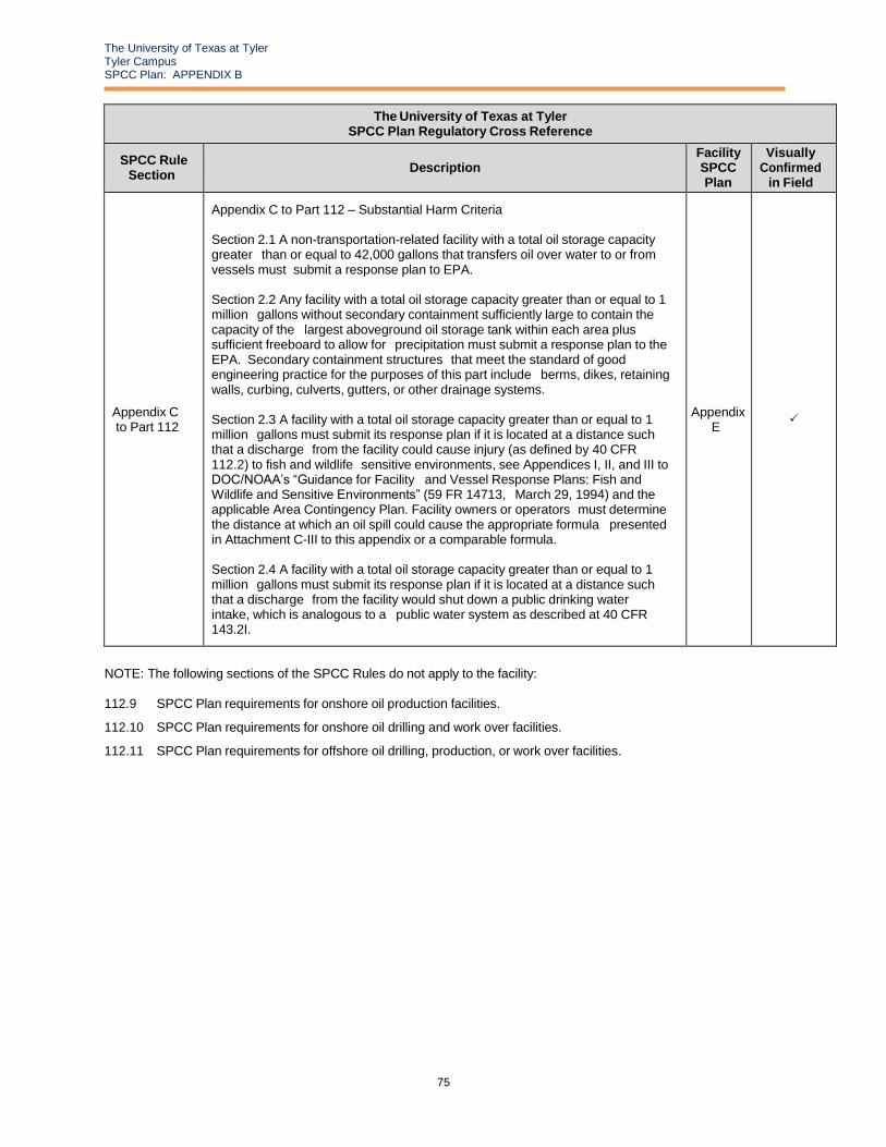
The University of Texas at Tyler Tyler Campus SPCC Plan: APPENDIX B
75
The University of Texas at Tyler SPCC Plan Regulatory Cross Reference
SPCC Rule Section
Description Facility SPCC Plan
Visually Confirmed
in Field
Appendix C to Part 112
Appendix C to Part 112 – Substantial Harm Criteria
Section 2.1 A non-transportation-related facility with a total oil storage capacity greater than or equal to 42,000 gallons that transfers oil over water to or from vessels must submit a response plan to EPA.
Section 2.2 Any facility with a total oil storage capacity greater than or equal to 1 million gallons without secondary containment sufficiently large to contain the capacity of the largest aboveground oil storage tank within each area plus sufficient freeboard to allow for precipitation must submit a response plan to the EPA. Secondary containment structures that meet the standard of good engineering practice for the purposes of this part include berms, dikes, retaining walls, curbing, culverts, gutters, or other drainage systems.
Section 2.3 A facility with a total oil storage capacity greater than or equal to 1 million gallons must submit its response plan if it is located at a distance such that a discharge from the facility could cause injury (as defined by 40 CFR 112.2) to fish and wildlife sensitive environments, see Appendices I, II, and III to DOC/NOAA’s “Guidance for Facility and Vessel Response Plans: Fish and Wildlife and Sensitive Environments” (59 FR 14713, March 29, 1994) and the applicable Area Contingency Plan. Facility owners or operators must determine the distance at which an oil spill could cause the appropriate formula presented in Attachment C-III to this appendix or a comparable formula.
Section 2.4 A facility with a total oil storage capacity greater than or equal to 1 million gallons must submit its response plan if it is located at a distance such that a discharge from the facility would shut down a public drinking water intake, which is analogous to a public water system as described at 40 CFR 143.2I.
Appendix E
NOTE: The following sections of the SPCC Rules do not apply to the facility: 112.9 SPCC Plan requirements for onshore oil production facilities.
112.10 SPCC Plan requirements for onshore oil drilling and work over facilities.
112.11 SPCC Plan requirements for offshore oil drilling, production, or work over facilities.

The University of Texas at Tyler Tyler Campus SPCC Plan: APPENDIX B
76
APPENDIX C SPILL REPORTING FORM (EXAMPLE)

The University of Texas at Tyler Tyler Campus SPCC Plan: APPENDIX B
77
REPORT OF PETROLEUM DISCHARGE, SPILLAGE, OR RELEASE
When did the incident occur? Date: Time:
Where did the incident occur?
How did the incident occur?
What and how much spilled? Is there a reportable quantity (RQ) associated with the material and was that RQ exceeded? (Reference the List of Lists)
Describe path of spill and any affected water bodies or areas of the environment. If fully contained, described how the spill was contained to prevent a release.
Under whose control was the product at the time of the incident? Provide their name, mailing address and telephone number (if not affiliated with UT Tyler).
List agencies that were notified as a result of this spill or note “NA” if reporting not required per Section 3.3 of SPCC Plan:
Date Time Person Making Notification Agency Notified Notes From
Conversation/Notification
Were there any injuries as a result of this incident? If so, list the names of exposed individual(s), their address, phone number, and describe the injuries.
What medical attention or advice did the exposed individual(s) receive?
Are there any known or anticipated health risks (acute or chronic) associated with the release of this chemical or medical advice that should be communicated?
The University of Texas at Tyler Tyler Campus SPCC Plan: APPENDIX B
78
What waste was generated as a result of clean-up activities? Describe how it was disposed (include waste classification and name of waste vendor).
What actions are being taken, or are proposed, to prevent reoccurrence of an incident of this type?
I hereby affirm that the foregoing statement is true to the best of my knowledge.
Name Title Address City/Town State Zip Signature Date

The University of Texas at Tyler Tyler Campus SPCC Plan: APPENDIX B
79
APPENDIX D INSPECTION LOGS
DIKE DRAINING LOG
ANNUAL INTEGRITY INSPECTION LOG

The University of Texas at Tyler Tyler Campus SPCC Plan: APPENDIX B
80
APPENDIX E CERTIFICATION OF THE APPLICABILITY
OF THE SUBSTANTIAL HARM CRITERIA
CHECKLIST
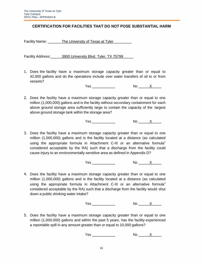
The University of Texas at Tyler Tyler Campus SPCC Plan: APPENDIX B
81
CERTIFICATION FOR FACILITIES THAT DO NOT POSE SUBSTANTIAL HARM
Facility Name: The University of Texas at Tyler
Facility Address: 3900 University Blvd. Tyler, TX 75799
1. Does the facility have a maximum storage capacity greater than or equal to
42,000 gallons and do the operations include over water transfers of oil to or from
vessels?
Yes No X
2. Does the facility have a maximum storage capacity greater than or equal to one
million (1,000,000) gallons and is the facility without secondary containment for each
above ground storage area sufficiently large to contain the capacity of the largest
above ground storage tank within the storage area?
Yes No X
3. Does the facility have a maximum storage capacity greater than or equal to one
million (1,000,000) gallons and is the facility located at a distance (as calculated
using the appropriate formula in Attachment C-III or an alternative formula1
considered acceptable by the RA) such that a discharge from the facility could
cause injury to an environmentally sensitive area as defined in Appendix D?
Yes No X
4. Does the facility have a maximum storage capacity greater than or equal to one
million (1,000,000) gallons and is the facility located at a distance (as calculated
using the appropriate formula in Attachment C-III or an alternative formula1
considered acceptable by the RA) such that a discharge from the facility would shut
down a public drinking water intake?
Yes No X
5. Does the facility have a maximum storage capacity greater than or equal to one
million (1,000,000) gallons and within the past 5 years, has the facility experienced
a reportable spill in any amount greater than or equal to 10,000 gallons?
Yes No X

The University of Texas at Tyler Tyler Campus SPCC Plan: APPENDIX B
82
CERTIFICATION FOR FACILITIES THAT DO NOT POSE SUBSTANTIAL HARM
I certify under penalty of law that I have personally examined and am familiar with the
information submitted in this document, and that based on my inquiry of those individuals
responsible for obtaining this information, I believe that the submitted information is true,
accurate, and complete.
Paula Tate Director, Environmental Health & Safety
Name Title
Signature Date

The University of Texas at Tyler Tyler Campus SPCC Plan: APPENDIX B
83
APPENDIX F TRAINING ROSTER

The University of Texas at Tyler Tyler Campus SPCC Plan: APPENDIX B
84
The University of Texas at Tyler SPCC Plan Training Roster
Date: Training Conducted By:
Employee Name Type of Training
(Circle One) Employee Signature
Initial / Refresher
Initial / Refresher
Initial / Refresher
Initial / Refresher
Initial / Refresher
Initial / Refresher
Initial / Refresher
Initial / Refresher
Initial / Refresher
Initial / Refresher
Initial / Refresher
Initial / Refresher
Initial / Refresher
Initial / Refresher
Initial / Refresher
Initial / Refresher
Initial / Refresher
Initial / Refresher
Initial / Refresher
Initial / Refresher
Initial / Refresher
Initial / Refresher
Initial / Refresher

The University of Texas at Tyler Tyler Campus SPCC Plan: APPENDIX B
85
APPENDIX G PHOTO LOG OF OIL STORAGE
LOCATIONS

The University of Texas at Tyler Tyler Campus SPCC Plan: APPENDIX B
86
Eagle’s Landing Building 13 Transformer (T18) Mobile Building 1 Portable Generator (G6)
PHY Gasoline Storage Tank (AST4)

The University of Texas at Tyler Tyler Campus SPCC Plan: APPENDIX B
87
FAC Generator (G1)

The University of Texas at Tyler Tyler Campus SPCC Plan: APPENDIX B
88
PPN Generator (G4)