Spherometer and Cylindrometer arXiv:1311.3602v1 [physics ... · comprehensive account of the...
43
arXiv:1311.3602v1 [physics.gen-ph] 14 Nov 2013 Coordinate Geometric Generalization of the Spherometer and Cylindrometer Sameen Ahmed Khan Engineering Department Salalah College of Technology (SCOT) Post Box No. 608, Postal Code: 211 Salalah, Sultanate of Oman. [email protected], http://SameenAhmedKhan.webs.com/ Abstract Spherometer is an instrument widely used for measuring the ra- dius of curvature of a spherical surface. Cylindrometer is a modified spherometer, which can measure the radii of both spherical and cylin- drical surfaces. Both of these instruments are based on a geometric relation unique to circles and spheres, from Euclidean geometry. A more general understanding is obtained using coordinate geometry. The coordinate geometric approach also enables a generalization of the spherometer and cylindrometer to devices, which can handle as- pherical surfaces. Here, we present the newly developed coordinate geometric approach and its applications. Keywords and phrases: Spherometer, Ball-Spherometer, Ring- Spherometer, Cylindrometer, Cylindro-Spherometer, Sphero-Cylindrometer, Ball-Cylindrometer, Quadricmeter, Coordinate Representation, Aspherical Surfaces, Quadratic Surfaces, Optical Techniques, Radius of Curvature. PACS: 06.30.Bp; 07.60.-j; 42.86.+b; 02.40.-k OCIS: 000.3860; 220.4610. Subj-class: MP-Mathematical Physics Mathematics Subject Classification: 14Q10, 51N20
Transcript of Spherometer and Cylindrometer arXiv:1311.3602v1 [physics ... · comprehensive account of the...
arX
iv:1
311.
3602
v1 [
phys
ics.
gen-
ph]
14
Nov
201
3
Coordinate Geometric Generalization of theSpherometer and Cylindrometer
Sameen Ahmed KhanEngineering Department
Salalah College of Technology (SCOT)Post Box No. 608, Postal Code: 211
Salalah, Sultanate of [email protected], http://SameenAhmedKhan.webs.com/
Abstract
Spherometer is an instrument widely used for measuring the ra-dius of curvature of a spherical surface. Cylindrometer is a modifiedspherometer, which can measure the radii of both spherical and cylin-drical surfaces. Both of these instruments are based on a geometricrelation unique to circles and spheres, from Euclidean geometry. Amore general understanding is obtained using coordinate geometry.The coordinate geometric approach also enables a generalization ofthe spherometer and cylindrometer to devices, which can handle as-pherical surfaces. Here, we present the newly developed coordinategeometric approach and its applications.
Keywords and phrases: Spherometer, Ball-Spherometer, Ring-Spherometer, Cylindrometer, Cylindro-Spherometer, Sphero-Cylindrometer,Ball-Cylindrometer, Quadricmeter, Coordinate Representation, AsphericalSurfaces, Quadratic Surfaces, Optical Techniques, Radius of Curvature.
PACS: 06.30.Bp; 07.60.-j; 42.86.+b; 02.40.-k
OCIS: 000.3860; 220.4610.
Subj-class: MP-Mathematical Physics
Mathematics Subject Classification: 14Q10, 51N20
2 Sameen Ahmed Khan
Contents1 Introduction 3
2 Spherometer: the Traditional Approach 5
3 Spherometer: A Coordinate Geometric Representation 8
4 Cylindrometer: A Coordinate Geometric Representation 11
5 Concluding Remarks 13
Appendix A.Ball-Spherometer 14
Appendix B.Ring-Spherometer 15
Appendix C.Cylindrometer 16
Appendix D.Aspherical Surfaces 19
Appendix E.Quadratic Surfaces 20E.1.1Classification of Quadratic Surfaces . . . . . . . . . . . . . . . . . . . . . . . 21E.1.2Quadratic Surfaces of Revolution . . . . . . . . . . . . . . . . . . . . . . . . 23
Appendix F.Quadricmeter 25
Appendix G.Optical Techniques 26
Appendix H.Radius of Curvature 27
Bibliography 27
List of Figures1 The Common Spherometer. . . . . . . . . . . . . . . . . . . . . . . . . . . . 42 The Geometry of the Spherometer. . . . . . . . . . . . . . . . . . . . . . . . 63 A Coordinate Representation of the Spherometer. . . . . . . . . . . . . . . . 94 A Coordinate Representation of the Cylindrometer. . . . . . . . . . . . . . . 115 The Ball-Spherometer fabricated by the author. . . . . . . . . . . . . . . . . 156 The Ring-Spherometer fabricated by the author. . . . . . . . . . . . . . . . 167 The Cylindrometer fabricated by the author. . . . . . . . . . . . . . . . . . 178 The Ball-Cylindrometer fabricated by the author. . . . . . . . . . . . . . . . 19
Coordinate Geometric Generalization of the Spherometer and Cylindrometer3
1 Introduction
Spherometers are precision instruments designed to measure the radius ofcurvature of spherical surfaces as the name suggests. They are particularlyuseful for situations, where only a portion of the spherical surface is available.Such situations are very common in the optics workshops, while fabricatinglenses and mirrors [1]-[9]. They were designed by the opticians of the early-nineteenth century (or even earlier).
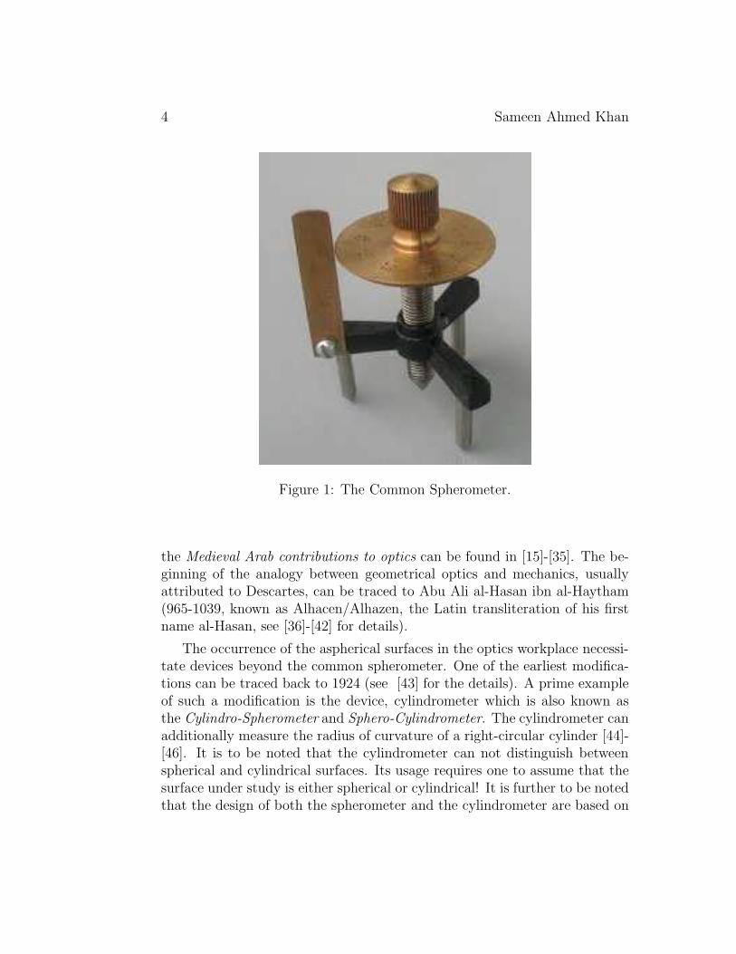
Although there is some thought that the spherometer was inventedby the French optician Laroue, the first spherometer of whichthere is positive knowledge was devised and named around 1810by Robert-Aglae Cauchoix, and made by the French mechanicianNicolas Fortin. Cauchoix’s design, a three-legged base supportinga central micrometer screw, was quickly adopted as the basic stan-dard and remains in use to this day. The Conservatorie Nationaldes Arts et Metiers in Paris has a spherometer made by Cauchoixand used by Biot that reads to 1/1000 millimeter [10].
Figure-1 has the very widely used tripod design. If the radii of bothsurfaces of the lens and the index of refraction of the lens material are known,the focal length can be found using the Lens-Maker’s equation [11].
P =1
f= (µ− 1)
[
1
R1
− 1
R2
+(µ− 1)d
µR1R2
]
, (1)
where P is the power of the lens, f is the focal length of the lens, µ is therefractive index of the lens material, R1 and R2 are the radii of curvatureof the lens surfaces and d is the thickness of the lens. In the thin lensapproximation, we have
P =1
f≈ (µ− 1)
[
1
R1
− 1
R2
]
. (2)
The error arising from the deviations from the tripod design have been alsostudied [12].
Many a time one is dealing with aspherical surfaces (non-spherical sur-faces). For instance one may be dealing with cylindrical lenses or paraboloidalreflectors [13]. The study of elliptic and hyperbolic mirrors dates back to thetime of Greeks [14] and the medieval Arabs. A comprehensive account of
4 Sameen Ahmed Khan
Figure 1: The Common Spherometer.
the Medieval Arab contributions to optics can be found in [15]-[35]. The be-ginning of the analogy between geometrical optics and mechanics, usuallyattributed to Descartes, can be traced to Abu Ali al-Hasan ibn al-Haytham(965-1039, known as Alhacen/Alhazen, the Latin transliteration of his firstname al-Hasan, see [36]-[42] for details).
The occurrence of the aspherical surfaces in the optics workplace necessi-tate devices beyond the common spherometer. One of the earliest modifica-tions can be traced back to 1924 (see [43] for the details). A prime exampleof such a modification is the device, cylindrometer which is also known asthe Cylindro-Spherometer and Sphero-Cylindrometer. The cylindrometer canadditionally measure the radius of curvature of a right-circular cylinder [44]-[46]. It is to be noted that the cylindrometer can not distinguish betweenspherical and cylindrical surfaces. Its usage requires one to assume that thesurface under study is either spherical or cylindrical! It is further to be notedthat the design of both the spherometer and the cylindrometer are based on
Coordinate Geometric Generalization of the Spherometer and Cylindrometer5
a geometric relation unique to circles and spheres, known since the times ofEuclid [14].
In this article, we present an alternate approach using coordinate geome-try in place of the Euclidean geometry. This provides us the familiar result forthe spherometer. The coordinate geometric approach to the spherometer wasdeveloped recently [47]. This approach, using the powerful techniques of coor-dinate geometry is suitable to a generalization of the traditional spherometerto devices, which can characterize aspherical surfaces [48]. Section-2 has a re-view of the traditional derivation of the spherometer formula. Section-3 has acomprehensive account of the coordinate geometric approach to the spherom-eter. In section-4 the coordinate geometric approach is extended to the cylin-drometer. In the Appendices, we shall describe the variants and modifica-tions of the common spherometer. We shall also consider other geometriessuch as regular polygons and the ring geometry. Appendix-A covers the ball-spherometer, which safeguards the surfaces under study from the sharp tipsof the spherometer legs. Appendix-B describes the ring-spherometer. Both ofthese appendices contain images of the instruments fabricated by the author.Appendix-C describes the cylindrometer which can be used to measure theradius of curvature of both spherical and cylindrical surfaces. This appendixalso covers the ball-cylindrometer fabricated by the author. Appendix-D hasa note on the aspherical surfaces. Appendix-E is dedicated to the class ofsurfaces known as the quadratic surfaces. Appendix-F contains the abstractof the quadricmeter invented by the author. This device can completelycharacterize the quadratic surfaces. The spherometer, cylindrometer and thequadricmeter are contact devices. Appendix-G is dedicated to optical tech-niques used to characterize surfaces. Appendix-H has a short note on theradius of curvature with a mathematical perspective.
2 Spherometer: the Traditional Approach
Since the beginning the spherometers consist of a tripod framework sup-ported on three fixed legs of equal lengths. Ideally the tips of the three legsform an equilateral triangle. The deviations from the ideal equilateral trian-gular geometry shall be discussed at the end of this section. A precisely cutmicrometer-screw is made to pass through a nut fixed at the centroid of theequilateral triangle. The movable micrometer-screw and the three fixed legsshould all be parallel to each other. The spherometer has two scales. One
6 Sameen Ahmed Khan
is the common millimeter scale, attached vertically to the tripod frame suchthat it is parallel to the axis o the micrometer-screw. The second scale is alarge circular disc (with typically a hundred divisions), which is attached tothe top of the micrometer-screw. The two scales together, working on theprinciple of the screw gauge provide an accurate measurement of the relativeheight of the tip of the micrometer-screw with respect to the plane containingthe tips of the three fixed legs. This height of the micrometer-screw is knownas sagitta. Accuracy requires the tips to be as sharp as possible.
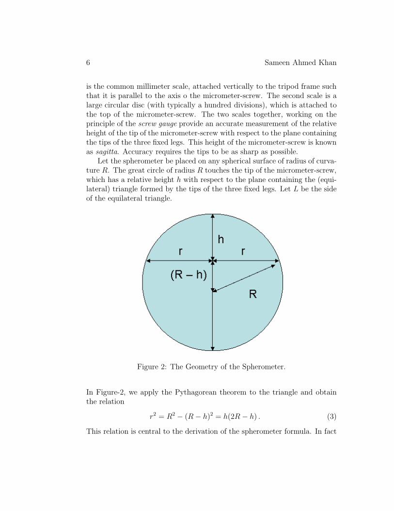
Let the spherometer be placed on any spherical surface of radius of curva-ture R. The great circle of radius R touches the tip of the micrometer-screw,which has a relative height h with respect to the plane containing the (equi-lateral) triangle formed by the tips of the three fixed legs. Let L be the sideof the equilateral triangle.
Figure 2: The Geometry of the Spherometer.
In Figure-2, we apply the Pythagorean theorem to the triangle and obtainthe relation
r2 = R2 − (R− h)2 = h(2R − h) . (3)
This relation is central to the derivation of the spherometer formula. In fact
Coordinate Geometric Generalization of the Spherometer and Cylindrometer7
such a relation exists for any two chords (which need not be perpendicular, asshown in the figure-2), making circle unique with respect to the other conicsections. Equation (3) leads to the following equivalent relations
R(h) =r2
2h+
h
2,
h(r) = R−√R2 − r2 =
r2
R +√R2 − r2
. (4)
The radius, r of the circumcircle and the length, L of the equilateral triangleobey the relation r = L/
√3. So, the radius of the sphere is given by
R(h) =L2
6h+
h
2, (5)
where h is the only measurable variable and L is a device constant. Fora given instrument, the smallest measurable radius of curvature is Rmin =R(h = L/
√3) = r = L/
√3, which is at h = r = L/
√3. The largest radius of
curvature is constrained by the least count of the micrometer-screw (typically0.01mm or better). The side L of the spherometer is several centimeters ormore depending on the size of spherical surface to be studied. The size of aspherometer depends on the application. To measure just the sagitta at thecentre of a mirror, one requires a spherometer with a base almost as big asthe mirror itself. Using a smaller base one can move around the spherometerto detect local high and low spots produced during the fabrication.
Since the spherometer is essentially a type of micrometer, it can be em-ployed for purposes other than measuring the curvature of a spherical surface.For example, it can be used to measure the thickness of a thin plate. To doso, the instrument is placed on a level plane surface and the screw turneduntil the point just touches it. Scales are read; screw is raised; the thin plateslipped under it; and the process is repeated. The difference between the tworeadings gives the required thickness.
During constructions there can be deviations from the ideal equilateraltriangle geometry. When the lengths of the sides of the triangle are L1, L2
and L3 respectively, the radius r of the circumcircle is given by
r =L1L2L3
4√
s(s− L1)(s− L2)(s− L3), (6)
8 Sameen Ahmed Khan
where s = (L1 + L2 + L3)/2 is the semi-perimeter of the triangle. Using therelation (6), we obtain
R =L21L
22L
23
32hs(s− L1)(s− L2)(s− L3)+
h
2. (7)
The formula in (7) generalizes the formula for the equilateral triangle in (5)and is due to Trikha and Bhatia (see [12] for the details).
The derivation, though elegant explicitly depends on two facts: firstlythat the plane-sections of a sphere are always circles and secondly the geo-metric relation in (3). It is well known that the plane-sections of asphericalsurfaces are in general not circles, but some other curves such as conic sections(ellipse, parabola and hyperbola). Moreover the corresponding geometric re-lations do not exist for conic sections. Analogous relations do exist for ellipse,parabola and hyperbola but work only at a single point, the vertex with haligned to the axis of each conic respectively. Thus any attempt to design aspherometer-type device, based on the geometric relations would work onlyat one point, whose location would of course not be known a priory. So, itis natural to look beyond the geometric relations. The coordinate geometryprovides a very natural choice [47].
3 Spherometer: A Coordinate Geometric
Representation
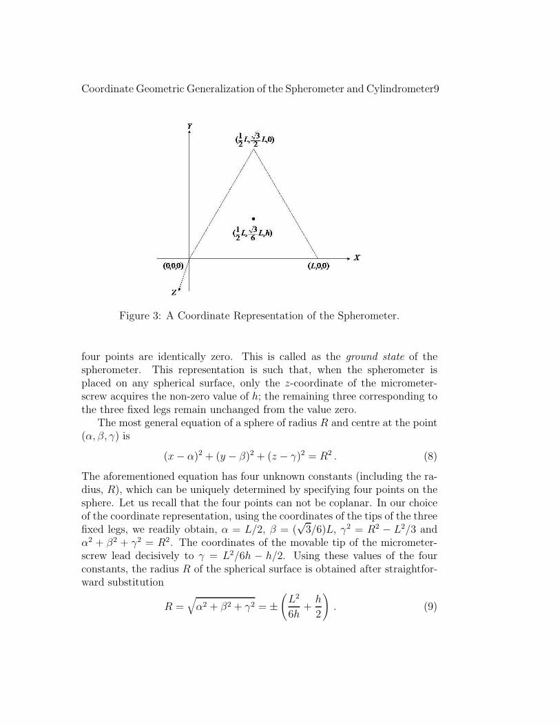
In the framework of the coordinate geometry, any geometric figure is specifiedby a certain number of points on it. For instance, a sphere is uniquelydetermined by specifying four points on it. The four points are of coursenot coplanar [49]. The situation in the spherometer is precisely the same!The three points are the tips of the fixed legs forming the equilateral triangleand the fourth point is the tip of the movable micrometer-screw. This formsthe basis of the coordinate geometric approach to the spherometer. Thecoordinate geometric representation of a sphere is not unique. A possiblerepresentation is as follows. We choose the plane of the equilateral triangleto lie completely in the X-Y plane, without any loss of generality. Then thetip of the micrometer-screw moves parallel to the Z-axis. Figure-3 has thedetails of the coordinate geometric representation.
The choice of our coordinate geometric representation is such that whenthe spherometer is placed on any plane surface, the z-coordinates of all the
Coordinate Geometric Generalization of the Spherometer and Cylindrometer9
Figure 3: A Coordinate Representation of the Spherometer.
four points are identically zero. This is called as the ground state of thespherometer. This representation is such that, when the spherometer isplaced on any spherical surface, only the z-coordinate of the micrometer-screw acquires the non-zero value of h; the remaining three corresponding tothe three fixed legs remain unchanged from the value zero.
The most general equation of a sphere of radius R and centre at the point(α, β, γ) is
(x− α)2 + (y − β)2 + (z − γ)2 = R2 . (8)
The aforementioned equation has four unknown constants (including the ra-dius, R), which can be uniquely determined by specifying four points on thesphere. Let us recall that the four points can not be coplanar. In our choiceof the coordinate representation, using the coordinates of the tips of the threefixed legs, we readily obtain, α = L/2, β = (
√3/6)L, γ2 = R2 − L2/3 and
α2 + β2 + γ2 = R2. The coordinates of the movable tip of the micrometer-screw lead decisively to γ = L2/6h − h/2. Using these values of the fourconstants, the radius R of the spherical surface is obtained after straightfor-ward substitution
R =√
α2 + β2 + γ2 = ±(
L2
6h+
h
2
)
. (9)
10 Sameen Ahmed Khan
The positive and negative signs are for the convex and concave surfaces re-spectively.
The technique of the coordinate geometry has enabled us to understandthe working of the spherometer in an entirely different manner. The tradi-tional approach is based on a geometric relation unique to circles and spheres.The newly developed coordinate geometric approach is independent of anysuch explicit geometric relations. The choice of the coordinate representationensures that the sphere is completely characterized by a single parameter,that is the height of the movable micrometer-screw. There are several advan-tages of using the coordinate geometric approach. It is capable of handlingany changes, which may arise during the fabrication of the spherometer orduring the measurements. Such changes are not uncommon, particularlywhen the spherometer is large, then it can deviate from its equilateral trian-gle geometry. In such a situation, it would suffice to revise the ground stateof the spherometer, even at the final stages while the measurements are beingmade. The greater advantage of using the coordinate geometric approach isthat it provides a better understanding of the spherometer design and fur-ther paves the way to modify and extend the tripod spherometer to deviceswhich can handle surfaces which need not be spherical. Let us recall that theaspherical surfaces do not have the required geometric relations available forcircles and spheres.
The equation of the sphere in terms of the four points lying on it can beexpressed in the form of the following determinant equation (see [49]-[52] fordetails).
∣
∣
∣
∣
∣
∣
∣
∣
∣
∣
∣
∣
x2 + y2 + z2 x y z 1x21 + y21 + z21 x1 y1 z1 1
x22 + y22 + z22 x2 y2 z2 1
x23 + y23 + z23 x3 y3 z3 1
x24 + y24 + z24 x4 y4 z4 1
∣
∣
∣
∣
∣
∣
∣
∣
∣
∣
∣
∣
= 0 . (10)
For the common spherometer with an equilateral triangle base, and our choiceof the coordinate representation in Figure-3, the determinant equation in (10)translates to
∣
∣
∣
∣
∣
∣
∣
∣
∣
∣
∣
∣
x2 + y2 + z2 x y z 10 0 0 0 1L2 L 0 0 1
L2 12L
√
32L 0 1
13L2 + h2 1
2L
√
36L h 1
∣
∣
∣
∣
∣
∣
∣
∣
∣
∣
∣
∣
= 0 . (11)
Coordinate Geometric Generalization of the Spherometer and Cylindrometer11
The above equation can be solved to describe the sphere completely. Onemay use MS EXCEL [53]-[57] or a versatile symbolic package such as theMATHEMATICA incorporating the graphic environment [58, 59].
4 Cylindrometer: A Coordinate Geometric
Representation
The traditional approach to the cylindrometer is described in detail inAppendix-C. The coordinate geometric approach to the cylindrometer is verysimilar to the one for the spherometer.
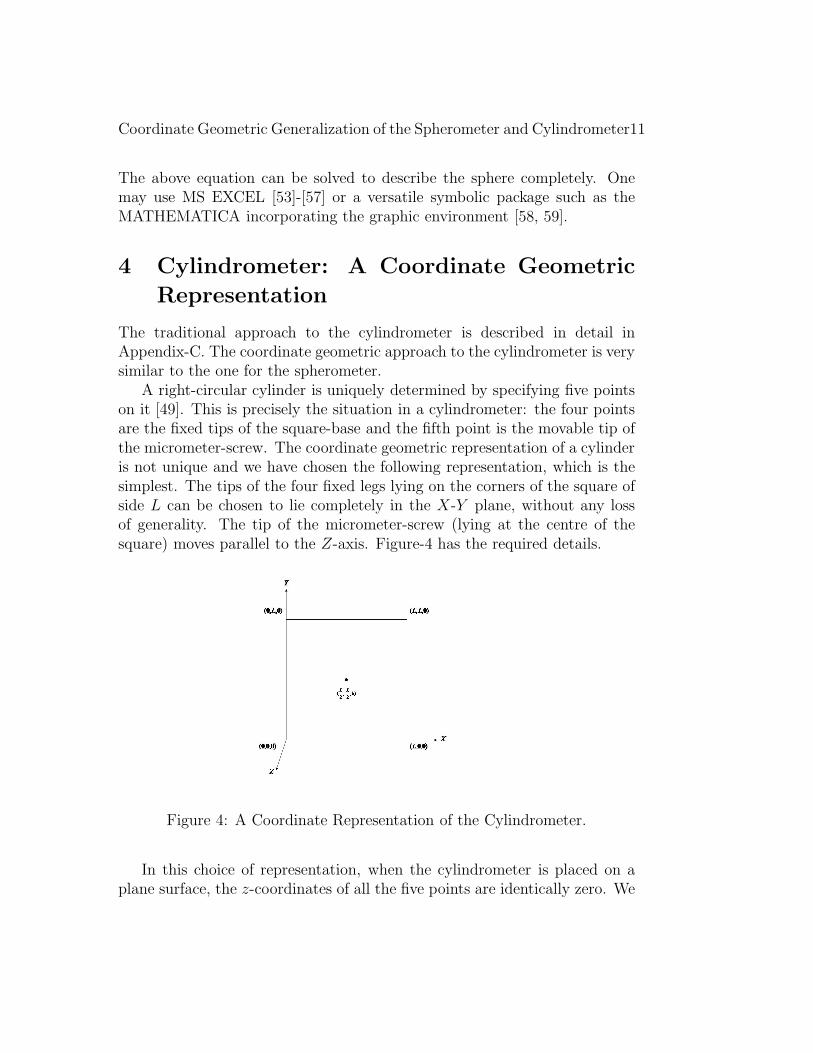
A right-circular cylinder is uniquely determined by specifying five pointson it [49]. This is precisely the situation in a cylindrometer: the four pointsare the fixed tips of the square-base and the fifth point is the movable tip ofthe micrometer-screw. The coordinate geometric representation of a cylinderis not unique and we have chosen the following representation, which is thesimplest. The tips of the four fixed legs lying on the corners of the square ofside L can be chosen to lie completely in the X-Y plane, without any lossof generality. The tip of the micrometer-screw (lying at the centre of thesquare) moves parallel to the Z-axis. Figure-4 has the required details.
Figure 4: A Coordinate Representation of the Cylindrometer.
In this choice of representation, when the cylindrometer is placed on aplane surface, the z-coordinates of all the five points are identically zero. We
12 Sameen Ahmed Khan
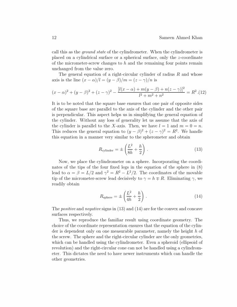
call this as the ground state of the cylindrometer. When the cylindrometer isplaced on a cylindrical surface or a spherical surface, only the z-coordinateof the micrometer-screw changes to h and the remaining four points remainunchanged from the value zero.
The general equation of a right-circular cylinder of radius R and whoseaxis is the line (x− α)/l = (y − β)/m = (z − γ)/n is
(x− α)2 + (y − β)2 + (z − γ)2 − [l(x− α) +m(y − β) + n(z − γ)]2
l2 +m2 + n2= R2 .(12)
It is to be noted that the square base ensures that one pair of opposite sidesof the square base are parallel to the axis of the cylinder and the other pairis perpendicular. This aspect helps us in simplifying the general equation ofthe cylinder. Without any loss of generality let us assume that the axis ofthe cylinder is parallel to the X-axis. Then, we have l = 1 and m = 0 = n.This reduces the general equation to (y − β)2 + (z − γ)2 = R2. We handlethis equation in a manner very similar to the spherometer and obtain
Rcylinder = ±(
L2
8h+
h
2
)
. (13)
Now, we place the cylindrometer on a sphere. Incorporating the coordi-nates of the tips of the four fixed legs in the equation of the sphere in (8)lead to α = β = L/2 and γ2 = R2 − L2/2. The coordinates of the movabletip of the micrometer-screw lead decisively to γ = h∓R. Eliminating γ, wereadily obtain
Rsphere = ±(
L2
4h+
h
2
)
. (14)
The positive and negative signs in (13) and (14) are for the convex and concavesurfaces respectively.
Thus, we reproduce the familiar result using coordinate geometry. Thechoice of the coordinate representation ensures that the equation of the cylin-der is dependent only on one measurable parameter, namely the height h ofthe screw. The sphere and the right-circular cylinder are the only geometries,which can be handled using the cylindrometer. Even a spheroid (ellipsoid ofrevolution) and the right-circular cone can not be handled using a cylindrom-eter. This dictates the need to have newer instruments which can handle theother geometries.
Coordinate Geometric Generalization of the Spherometer and Cylindrometer13
5 Concluding Remarks
We have reviewed the common spherometer and its modified avatars suchas the ring-spherometer and the ball-spherometer. We have also reviewedthe lesser known cylindrometer and seen how it can be used to measure theradii of curvature of both right-circular cylindrical surfaces and sphericalsurfaces [45, 46]. The idea of the ball-spherometer has been extended to thecylindrometer resulting in a ball-cylindrometer (Appendices A and C havethe details along with the images). It is essential to look beyond and gener-alize the common spherometer and the cylindrometer to devices, which canenable the study of a wider range of surfaces occurring in science and engi-neering [48]. Coordinate geometry provides a natural framework for creationof such devices [47].
In coordinate geometry, a given figure is uniquely determined by speci-fying a certain number of points on it. This number varies from figure tofigure. For instance, a sphere is completely characterized by its radius andthe four points lying on it are sufficient to fix its radius. This demands thespherometer to be a four-point device. Hence its design has four points: thethree points are the tips of the three fixed legs and the fourth point is the tipof the movable micrometer-screw. The choice of the coordinate representa-tion ensures that there is only one variable parameter, h corresponding to theradius R of the sphere. A right-circular cylinder is characterized by its radius(the length of the cylinder is not under discussion in the present context),which can be fixed by five points on it. Cylindrical symmetry permits pointsto be coplanar. Hence, the cylindrometer is a five-point device. A judiciouschoice of the coordinate representation ensures that, we are again able toexpress the radius R of the cylindrical surface in terms of a single devicevariable, which is again the height of the movable tip of the micrometer-screw of the cylindrometer. A quadratic surface is described by the generalsecond-order equation, which has nine independent constants [48, 51]. Thenine points (no four points being coplanar) uniquely determine the quadraticsurface. So, we require a nine point device to identify and completely char-acterize any quadratic surface. The four-point coordinate representation ofa spherometer and the five-point coordinate representation of a cylindrom-eter, has been generalized to a nine-point device, the quadricmeter, whichgenerates the equation of the quadratic surfaces in terms of measurable lab-oratory parameters [60, 61]. The quadricmeter is the instrument devised toidentify, distinguish and measure the various parameters (including the axis,
14 Sameen Ahmed Khan
foci, latera recta, directrix) completely characterizing the important class ofsurfaces known as the quadratic surfaces. Quadratic surfaces (also known asquadrics and conicoids) include a wide range of commonly encountered sur-faces including, cone, cylinder, ellipsoid, elliptic cone, elliptic cylinder, elliptichyperboloid, elliptic paraboloid, hyperbolic cylinder, hyperbolic paraboloid,paraboloid, sphere, and spheroid. The complete characterization is done us-ing the standard techniques of coordinate geometry. With a conventionalspherometer it is possible only to measure the radii of spherical surfaces.Cylindrometer can measure the radii of curvature of a cylindrical surfaces inaddition to the spherical surfaces. In both the spherometer and the cylin-drometer one has to necessarily assume the surface to be either spherical orcylindrical respectively. In the case of the quadricmeter, there are no such as-sumptions [60, 61] as it can distinguish one quadratic surface from the other.The nomenclature quadricmeter originates from the word quadrics used forquadratic surfaces and was preferred over conicoidmeter.
Appendix A.Ball-Spherometer
In order to ensure higher accuracy, the spherometer is required to havesharper legs. This is sure to harm the surfaces under study. This is moretrue, when the surfaces are large (as in the telescope mirrors) and the requiredspherometers are bound to be heavy. One of the most widely used methodsto handle this situation is to replace the sharp tips of the three legs of thespherometer with balls of radius r0. The resulting spherometer is called aball-spherometer and the basic relation in (4) for the radius of curvature ismodified to
R(h) =r2
2h+
h
2± r0 , (A.1)
where the positive and negative signs are for the convex and concave surfacesrespectively [5]. The idea of replacing the sharper tips with balls has beenextended to the cylindrometer. The author of this article strongly advocatesto use the ball-cylindrometer resulting from this replacement.
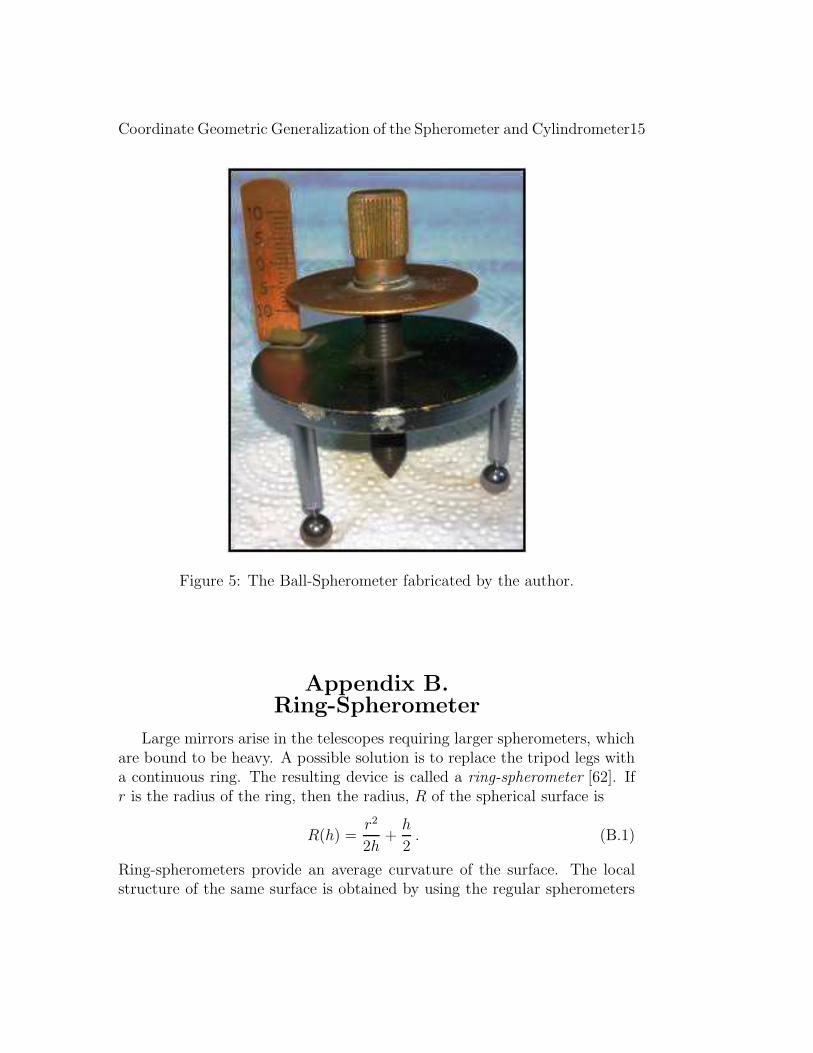
Coordinate Geometric Generalization of the Spherometer and Cylindrometer15
Figure 5: The Ball-Spherometer fabricated by the author.
Appendix B.Ring-Spherometer
Large mirrors arise in the telescopes requiring larger spherometers, whichare bound to be heavy. A possible solution is to replace the tripod legs witha continuous ring. The resulting device is called a ring-spherometer [62]. Ifr is the radius of the ring, then the radius, R of the spherical surface is
R(h) =r2
2h+
h
2. (B.1)
Ring-spherometers provide an average curvature of the surface. The localstructure of the same surface is obtained by using the regular spherometers
16 Sameen Ahmed Khan
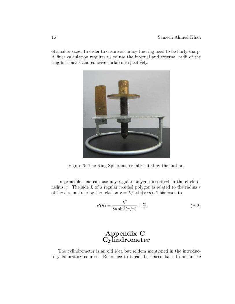
of smaller sizes. In order to ensure accuracy the ring need to be fairly sharp.A finer calculation requires us to use the internal and external radii of thering for convex and concave surfaces respectively.
Figure 6: The Ring-Spherometer fabricated by the author.
In principle, one can use any regular polygon inscribed in the circle ofradius, r. The side L of a regular n-sided polygon is related to the radius rof the circumcircle by the relation r = L/2 sin(π/n). This leads to
R(h) =L2
8h sin2(π/n)+
h
2. (B.2)
Appendix C.Cylindrometer
The cylindrometer is an old idea but seldom mentioned in the introduc-tory laboratory courses. Reference to it can be traced back to an article
Coordinate Geometric Generalization of the Spherometer and Cylindrometer17
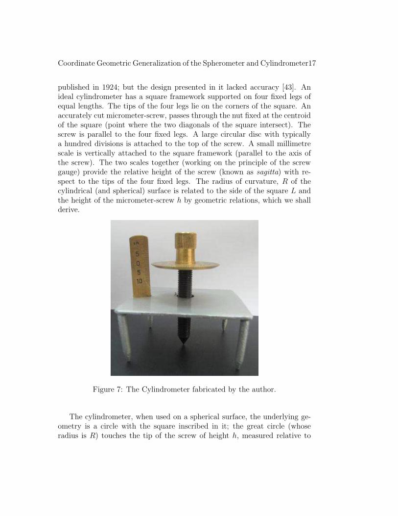
published in 1924; but the design presented in it lacked accuracy [43]. Anideal cylindrometer has a square framework supported on four fixed legs ofequal lengths. The tips of the four legs lie on the corners of the square. Anaccurately cut micrometer-screw, passes through the nut fixed at the centroidof the square (point where the two diagonals of the square intersect). Thescrew is parallel to the four fixed legs. A large circular disc with typicallya hundred divisions is attached to the top of the screw. A small millimetrescale is vertically attached to the square framework (parallel to the axis ofthe screw). The two scales together (working on the principle of the screwgauge) provide the relative height of the screw (known as sagitta) with re-spect to the tips of the four fixed legs. The radius of curvature, R of thecylindrical (and spherical) surface is related to the side of the square L andthe height of the micrometer-screw h by geometric relations, which we shallderive.
Figure 7: The Cylindrometer fabricated by the author.
The cylindrometer, when used on a spherical surface, the underlying ge-ometry is a circle with the square inscribed in it; the great circle (whoseradius is R) touches the tip of the screw of height h, measured relative to
18 Sameen Ahmed Khan
the plane containing the tips of the four fixed legs. When the cylindrometeris placed on a cylindrical surface, the two opposite sides of the square baseget aligned parallel to the axis of the cylinder; consequently the tips of twolegs lie on the circle defining the cylinder and the height h of the screw ismeasured relative to the plane containing the tips of these four legs.
For the cylinder, r is related to the side, L of the square by the relation,r = L/2, and we obtain
Rcylinder =L2
8h+
h
2. (C.1)
For the sphere, r = L/√2, leading to
Rsphere =L2
4h+
h
2. (C.2)
The above relations are structurally similar to the formula in Equation (5)for a common spherometer with the tripod base. For a given instrument,the smallest measurable radius of curvature for a cylinder and sphere areRmin
cylinder = L/2 and Rminsphere = L/
√2 respectively. The largest radius of cur-
vature is constrained by the least count of the micrometer-screw (0.01mmor better). The side L of the cylindrometer is several centimetres or moredepending on the size of surface to be studied. The size of a cylindrometerdepends on the application. To measure just the sagitta at the centre of amirror, one requires a cylindrometer with a base almost as big as the mirroritself. Using a smaller base one can move around the cylindrometer to detectlocal high and low spots produced during the fabrication.
The design of the cylindrometer with a square base was patented in1972 by Gur Iqbal Singh Hunjan, with the title, Cylindro-Spherometer (see[44] for complete specifications). The other name of the device is Sphero-Cylindrometer. It is very surprising that the cylindrometer is neither men-tioned in the introductory books and nor it is available from the scientificinstruments companies. Cylindrometers fabricated in-house are used in manylaboratories world-wide [63].
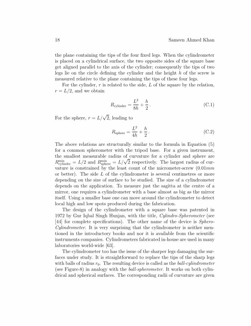
The cylindrometer too has the issue of the sharper legs damaging the sur-faces under study. It is straightforward to replace the tips of the sharp legswith balls of radius r0. The resulting device is called as the ball-cylindrometer(see Figure-8) in analogy with the ball-spherometer. It works on both cylin-drical and spherical surfaces. The corresponding radii of curvature are given
Coordinate Geometric Generalization of the Spherometer and Cylindrometer19
Figure 8: The Ball-Cylindrometer fabricated by the author.
by
Rcylinder =L2
8h+
h
2± r0 ,
Rsphere =L2
4h+
h
2± r0 , (C.3)
where the positive and negative signs are for the convex and concave surfacesrespectively.
Appendix D.Aspherical Surfaces
One often needs to quantify aspherical surfaces, such as the parabolicmirrors. The traditional spherometers can be used to a certain extent for this
20 Sameen Ahmed Khan
purpose. Many aspheric surfaces can be approximated as conic sections ofrevolution. Conic sections are generally easier to test than a general asphere,because there are geometric null tests for conics [7]. Incorporating the conicconstant K = −e2, where e is the eccentricity of the conic section, the basicequation (4) modifies to
z(r) =r2
R +√
R2 − (K + 1)r2. (D.1)
In this equation z(r) = h(r) is the surface height, r =√
(x2 + y2) is theradial position and R is the radius of curvature. The types of conic surfaces,determined by the conic constant K = −e2, are as follows
K < −1 HyperboloidK = −1 Paraboloid−1 < K < 0 Prolate Ellipsoid (rotated about its major axis)K = 0 SphereK > 0 Oblate Ellipsoid (rotated about its minor axis)
Table-1: Types of Conic Surfaces
A series expansion of equation (D.1) can be used to calculate the asphericdeparture [11]. If the location of the vertex is known, then a pair of readingsusing two ring-spherometers of different sizes, close to the vertex can beuseful in assessing such surfaces. However, such a procedure would requirelot of skill.
Appendix E.Quadratic Surfaces
Many a time one is dealing with aspherical surfaces (non-spherical sur-faces). For instance one may be dealing with cylindrical lenses or paraboloidalreflectors [13]. The study of elliptic and hyperbolic mirrors dates back to thetime of Greeks [14] and the medieval Arabs [15]-[35]. In telescopes and otheroptical instruments, the mirrors and lenses generally have a shape coming
Coordinate Geometric Generalization of the Spherometer and Cylindrometer21
from quadratic surfaces [4, 5]. One also finds them in aerodynamic modeling.Such situations, involving aspherical surfaces are very common across almostall scientific disciplines. Quadratic surfaces (also known as quadrics and con-icoids) include a wide range of commonly encountered surfaces including,cone, cylinder, ellipsoid, elliptic cone, elliptic cylinder, elliptic hyperboloid,elliptic paraboloid, hyperbolic cylinder, hyperbolic paraboloid, paraboloid,sphere, and spheroid [51]. From the aforementioned list it is evident thatone comes across the quadratic surfaces in various areas of science and engi-neering. Quadratic surfaces have been a basic primitive in computer graphicsfor a long time and their properties and techniques for visualization are verywell researched. Quadratic surfaces are important in geometric modeling.Modeling of three dimensional objects with quadratic surface patches is veryeffective. Complicated surfaces can be approximated as patches of quadraticsurfaces. In this appendix, we shall describe the algebraic classification of thequadratic surfaces into the seventeen standard-form types along with theircorresponding equations. We shall also state the conditions under which agiven quadric is a quadratic surface of revolution.
E.1.1 Classification of Quadratic Surfaces
A quadratic surface is described by the general second-order equation
ax2 + by2 + cz2 + 2fyz + 2gzx+ 2hxy + 2px+ 2qy + 2rz + d = 0 . (E.1)
Equation (E.1) has ten constants of which one is redundant since the equa-tion can be divided by any one of the constants leading to nine independentconstants. Plane sections of a quadratic surface are conic sections namelyellipse, parabola and hyperbola (see [49, 50] for details). Quadratic surfaceshave been fully classified and there are 17 standard-form types [51]. Theseare enumerated in Table-1. Higher order surfaces have been studied exten-sively. Cubic surfaces are algebraic surface of order three and have been fullyclassified. However, quartic surfaces and higher order surfaces have not beenfully classified [51, 52].
In order to classify the quadratic surfaces, following the notation in [51],we define
e =
a h gh b fg f c
22 Sameen Ahmed Khan
E =
a h g ph b f qg f c rp q r d
ρ3 = rank(e)
ρ4 = rank(E)
∆ = det(E) . (E.2)
Let k1, k2 and k3 be the eigenvalues (characteristic roots) of the matrix e,that is the roots of the characteristic equation
∣
∣
∣
∣
∣
∣
∣
a− x h gh b− x fg f c− x
∣
∣
∣
∣
∣
∣
∣
= 0 . (E.3)
We further define
k =
{
1 if the signs of the nonzero ks are the same,0 otherwise.
(E.4)
Using the above defined quantities the seventeen quadrics and their equationsin reduced form, are listed in Table-2. It is to be noted that sphere is notseparately listed as it is a special case of the ellipsoid (a = b = c). Likewise,the right-circular cone (special case of the elliptic cone, a = b) and the right-circular cylinder (special case of the elliptic cylinder, a = b) are also not listedseparately. Any quadratic surface described by the general equation (E.1) canbe transformed to one of the seventeen standard-form types using translationsand rotations of the coordinate axes.
Coordinate Geometric Generalization of the Spherometer and Cylindrometer23
S. No. Surafce Equations Conditionsρ3 ρ4 sign(∆) k
1 Coincident Planes x2 = 0 1 1
2 Ellipsoid (Imaginary) x2
a2+ y2
b2+ z2
c2= −1 3 4 + 1
3 Ellipsoid (Real) x2
a2+ y2
b2+ z2
c2= 1 3 4 − 1
4 Elliptic Cone (Imaginary) x2
a2+ y2
b2+ z2
c2= 0 3 3 1
5 Elliptic Cone (Real) x2
a2+ y2
b2= z2 3 3 0
6 Elliptic Cylinder (Imaginary) x2
a2+ y2
b2= −1 2 3 1
7 Elliptic Cylinder (Real) x2
a2+ y2
b2= 1 2 3 1
8 Elliptic Paraboloid x2
a2+ y2
b2= z 2 4 − 1
9 Hyperbolic Cylinder x2
a2− y2
b2= −1 2 3 0
10 Hyperbolic Paraboloid x2
a2− y2
b2= −z 2 4 + 0
11 Hyperboloid of one sheet x2
a2+ y2
b2− z2
c2= 1 3 4 + 0
12 Hyperboloid of two sheets x2
a2+ y2
b2− z2
c2= −1 3 4 − 0
13 Intersecting Planes (Imaginary) x2
a2+ y2
b2= 0 2 2 1
14 Intersecting Planes (Real) x2
a2− y2
b2= 0 2 2 0
15 Parabolic Cylinder x2 + 2rz = 0 1 316 Parallel Planes (Imaginary) x2 = −a2 1 217 Parallel Planes (Real) x2 = a2 1 2
Table-2: Seventeen Standard-Form Types of Quadrics
In passing, we note that the classification of the quantum mechanicalquadratic Hamiltonians into classes with a physically relevant representationhas been done. In the context of optics such a classification has been done byenumerating the Hamiltonian orbits [64]-[65]. For a comprehensive accountof the Hamiltonian Orbits, see the book in [24].
E.1.2 Quadratic Surfaces of Revolution
Quadratic surfaces of revolution (cones, cylinders, ellipsoids, hyperboloids,paraboloids) are common; for instance the mirrors of telescopes generallyhave rotational symmetry. A quadric of revolution is determined by at mostsix points on it. The general equation of the quadratic surfaces is accompa-nied with certain conditions coming from the rotational symmetry, reducingthe number of independent constants to six (or less). For instance the sphereis determined by four points on it; right-circular cone, the right-circular cylin-
24 Sameen Ahmed Khan
der and the paraboloid of revolution are determined by five points each re-spectively.
Theorem 1 A quadric is a surface of revolution if and only if it has twoequal non-zero characteristic roots; i.e., the non-zero eigenvalues of the char-acteristic equation (E.3) repeat twice.
This theorem translates into following three possible cases:
Case–1: None of the mixed-terms constants, f , g, and h are zero.
If fgh 6= 0, then
F
f=
G
g=
H
h, (E.5)
where F , G, and H are the cofactors of f , g, and h in the matrix e (i.e,F = gh− af , G = hf − bg, and H = fg − ch).
Case–2: If fgh = 0, then at least two of the mixed-terms constants, f , g,and h are zero (i.e, two are necessarily zero and the third one need notbe zero).
If f = 0, g = 0, h 6= 0, then
(a− c)(b− c) = h2 . (E.6)
If g = 0, h = 0, f 6= 0, then
(b− a)(c− a) = f 2 . (E.7)
If f = 0, h = 0, g 6= 0, then
(a− b)(c− b) = g2 . (E.8)
Case–3: When the mixed-terms constants, f , g, and h are all zero.
If f = 0, g = 0, and h = 0, then
(a− b)(b− c)(c− a) = 0 , ⇒ a = b or b = c or c = a . (E.9)
Equations (E.5)-(E.9) summarize the necessary and sufficient conditions im-posed on the general equation of second degree to represent a surface ofrevolution [49]. It is interesting to note that the conditions are expressedin terms of the quadratic constants alone and none of the constants of thelinear terms (p, q and r) are used.
Coordinate Geometric Generalization of the Spherometer and Cylindrometer25
Appendix F.
Quadricmeter(Abstract of the Patent Application)1
Abstract
Quadricmeter is the instrument devised to identify (distinguish)and measure the various parameters (axis, foci, latera recta, directrix,etc.,) completely characterizing the important class of surfaces knownas the quadratic surfaces. Quadratic surfaces (also known as quadrics)include a wide range of commonly encountered surfaces including,cone, cylinder, ellipsoid, elliptic cone, elliptic cylinder, elliptic hyper-boloid, elliptic paraboloid, hyperbolic cylinder, hyperbolic paraboloid,paraboloid, sphere, and spheroid. Quadricmeter is a generalized formof the conventional spherometer and the lesser known cylindrometer(also known as the Cylindro-Spherometer and Sphero-Cylindrometer).With a conventional spherometer it was possible only to measure theradii of spherical surfaces. Cylindrometer can measure the radii ofcurvature of a cylindrical surface in addition to the spherical surface.In both the spherometer and the cylindrometer one assumes the sur-face to be either spherical or cylindrical respectively. In the case ofthe quadricmeter, there are no such assumptions.
1This is the abstract of the patent application as it appeared in:
• Sameen Ahmed Khan, Quadricmeter, Official Journal ofthe Patent Office, Issue No. 43/2008, Part-I, pp. 25296(24 October 2008). Application No.: 2126/MUM/2008 A,International Classification: B69G1/36, Controller Generalof Patents Designs and Trade Marks, Government of India.http://ipindia.nic.in/ipr/patent/journal_archieve/journal_2008/patent_journal_200
http://ipindia.nic.in/ipr/patent/journal_archieve/journal_2008/pat_arch_102008/of
http://www.ipindia.nic.in/, (patent in process,http://SameenAhmedKhan.webs.com/quadricmeter.html).
See the references [60, 61] for details and updates.
26 Sameen Ahmed Khan
Appendix G.Optical Techniques
Apart from the contact techniques, it is also possible to use the opticaltechniques. The major source of inaccuracy in using a spherometer (andits variants describes in this article) is in determining the exact point ofcontact between the probe and the surface being tested. Sharper legs ofthe spherometer can damage the surface and this can be circumvented to agood extent by the use of the ball-spherometer (and the ball-cylindrometersuggested by the author in this note). This necessitates the creation of non-contact methods.
Optical techniques based on the interference patterns provide one suchmeans of non- contact procedure to study the surfaces [63]. In some spherom-eters the point of contact is determined by observing the Newton’s ring in-terference pattern formed between the test surface and an optical surfacemounted on the end of the probe. As the probe is brought up to the surface,the ring pattern expands, but when the point of contact is reached, no fur-ther motion occurs. Interferometry is a precise and non-destructive tool anddetermines other optical parameters (such as thickness, refractive index) inaddition to the radius of curvature. Interferometer are also used for mea-suring surface flatness of plano optical elements such as mirrors, prisms andwindows.
A Fizeau interferometer can also be used to measure radius of curvatureof a surface. A surface having a long radius of curvature can be comparedinterferometrically with a flat surface to yield Newton’s rings. The Fizeauinterferometer is the most commonly used interferometer for testing opticalcomponents and systems used aboard space borne or space-related instru-mentation.
Non-contacting and whole-field method of measuring curvatures using amoving laser source and an image-shearing camera have been also developed.There are also procedures for the surface reconstruction based on the trans-mitted wavefront. The reconstructed surface is a complete surface includingits radius of curvature [66, 67].
Coordinate Geometric Generalization of the Spherometer and Cylindrometer27
Appendix H.Radius of Curvature
Curvature is the amount by which a geometric object deviates from beingflat, or straight in the case of a line [68, 69]. The curvature κ of a circle isdefined as the reciprocal of its radius R. Smaller circles bend more sharply,and hence have higher curvature. The circles and spheres are unique as theyhave a constant curvature. The curvature of a smooth curve is defined asthe curvature of its osculating circle at each point. Let y = f(x), then theradius of curvature is given by
R =
[
1 +(
dydx
)2]3/2
∣
∣
∣
d2ydx2
∣
∣
∣
. (H.1)
For example, in an ellipse with major axis 2a and minor axis 2b, the verticeson the major axis have the smallest radius of curvature of any points R = b2/aand the vertices on the minor axis have the largest radius of curvature of anypoints R = a2/b.
If the curve is given parametrically by the functions x(t) and y(t), thenthe radius of curvature is
R =[x2 + y2]
3/2
|xy − yx| , (H.2)
where x = dx/dt, x = d2x/dt2, y = dy/dt and y = d2x/dt2.
References
[1] J. N. Jaiswal, Practical Physics, (Laxmi Publications, New Delhi, India,2006). http://www.laxmipublications.com/.
[2] A. A. Rama Krishna and V. Satyanarayana, Practical Physics, (VikramPublishers, Hyderabad, India, 2005).
[3] Allan Mackintosh (Editor), Advanced Telescope MakingTechniques, (Willmann-Bell, Inc., Virginia, USA, 1986).http://www.willbell.com/.
28 Sameen Ahmed Khan
[4] Daniel Malacara and Brian J. Thompson (Editors), Handbook of OpticalEngineering, (Marcel Dekker Inc., New York, USA, 2001).
[5] Hank H. Karow, Fabrication Methods for Precision Optics, (WileySeries in Pure and Applied Optics), (John Wiley & Sons, 2004).http://eu.wiley.com/.
[6] E. J. Tew, Jr., Measurement Techniques Used in the OpticsWorkshop, Applied Optics, 5, 695-700 (1966). Digital Object Identi-fier (DOI): http://dx.doi.org/10.1364/AO.5.000695.
[7] D. E. Stoltzmann and P. Ceravolo, Ross null test for conic mirrors,Applied Optics, 32, 1189-1199 (1993). Digital Object Identifier (DOI):http://dx.doi.org/10.1364/AO.32.001189.
[8] Sameen Ahmed Khan, Lecture Notes in Physics, Salalah College of Tech-nology E-Learning Website, http://www.sct.edu.om/ (2010).
[9] Sameen Ahmed Khan, Physics Laboratory Manual, Salalah College ofTechnology E-Learning Website, http://www.sct.edu.om/ (2010).
[10] Robert Bud and Deborah Jean Warner, Instruments ofScience: An Historical Encyclopedia, Taylor & Fran-cis, New York, US, pp. 569, 1998. Digital Object Iden-tifier (DOI): http://dx.doi.org/10.1007/s00897990278a.http://www.taylorandfrancis.com/.
[11] David Anderson and Jim Burge, Optical Fabrication, in Handbook of Op-tical Engineering, (Editors: Daniel Malacara and Brian J. Thompson),Marcel Dekker, New York, USA, Chapter 28, pp. 915-955 (2001).
[12] S. K. Trikha and A. S. Bhatia, General Formula for Radius ofCurvature of a Spherical Surface with a Spherometer, AmericanJournal of Physics, 26(3), 193 (1958). Digital Object Identifier (DOI):http://dx.doi.org/10.1119/1.1934619.
[13] Ajoy Ghatak, Optics, (Tata McGraw-Hill, Delhi, India, 1988).http://www.tmhshop.com/.
[14] Eugene Hecht, Optics, (Addison-Wesley, 1990).http://www.pearsoned.co.uk/Imprints/Addison-Wesley/.
Coordinate Geometric Generalization of the Spherometer and Cylindrometer29
[15] Roshdi Rashed, A Pioneer in Anaclastics Ibn Sahl on Burn-ing Mirrors and Lenses, ISIS, 81 464-491 (1990), The Univer-sity of Chicago Press. http://www.jstor.org/stable/233423 andhttp://press.uchicago.edu/ucp/journals/journal/isis.html
[16] Roshdi Rashed, Geometrie et Dioptrique au Xe siecle: IbnSahl, al-Quhı et Ibn al-Haytham, Collection Sciences et Philoso-phie Arabes, Textes et Etudes, Les Belles Lettres, Paris, France (1993).http://www.lesbelleslettres.com/.
[17] Roshdi Rashed, A Polymath in the 10th Century, Sci-ence, 297, 773 (2 August 2002). Digital Object Identifier (DOI):http://dx.doi.org/10.1126/science.1074591.
[18] David C. Lindleberg, Medieval Islamic Achievement in Optics, Op-tics & Photonics News (OPN), 14(7), 30-35 (July 2003). Digital ObjectIdentifier (DOI): http://dx.doi.org/10.1364/OPN.14.7.000030.http://www.osa-opn.org/.
[19] Akhlesh Lakhtakia, Optics in Medieval Islam, Optics & PhotonicsNews (OPN), 14(9), 6 (September 2003). http://www.osa-opn.org/.
[20] Abdus Salam, in Ideals and Realities, (C. H. Lai and A. Kid-wai, eds.), 3rd ed., World Scientific, Singapore, pp. 283 (1989).http://www.worldscientific.com/worldscibooks/10.1142/0988.
[21] Abdus Salam, in Renaissance of Sciences in Is-lamic Countries, (H. R. Dalafi and M. H. A. Has-san, eds.), World Scientific, Singapore, pp. 31 (1994).http://www.worldscientific.com/worldscibooks/10.1142/0884.
[22] Zakaria Virk, Europe’s Debt to the IslamicWorld, Review of Religions, 98(07), 36-52 (July 2003).http://www.reviewofreligions.org/download/RR200307.pdf#page=36.
[23] K. B. Wolf and G. Krotzsch. Geometry and dynam-ics in refracting systems, European Journal of Physics,16(1), 14-20 (January 1995). Digital Object Identifier (DOI):http://dx.doi.org/10.1088/0143-0807/16/1/003.
30 Sameen Ahmed Khan
[24] K. B. Wolf, Geometric Optics on Phase Space, pp. 57-58 (Springer,2004). http://www.springer.com/physics/optics+%26+lasers/book/978-3-540-22039-
[25] M. Salih, M. Al-Amri and M. El-Gomati, The Miracle ofLight, A World of Science, 3(4), 2-7 (October-December 2005).http://www.unesco.org/science/infocus_full_oct_05.shtml.
[26] M. Salih, M. Al-Amri and M. El-Gomati, The Miracle of Light,Natural Science Quarterly Newsletter, UNESCO; Publication No.385 (2006), (Foundation for Science Technology and Civilization,http://www.fstc.org.uk/).
[27] Sameen Ahmed Khan, Medieval Arab Understanding ofthe Rainbow Formation, Europhysics News, 37(3), 10(May/June 2006). (Publication of the European Physical Society).http://www.europhysicsnews.org/.
[28] Sameen Ahmed Khan, Science Historian Roshdi Hifni RashedAwarded the King Faisal International Prize for 2007, Euro-physics News, 38(2), 7 (March-April 2007). (Publication of the EuropeanPhysical Society). http://www.europhysicsnews.org/. Website of theKing Faisal Foundation: http://www.kff.com/.
[29] Sameen Ahmed Khan, Science Historian Roshdi Hifni RashedAwarded the King Faisal International Prize for 2007, AAPPSBulletin, 17(4), 37 (August 2007). (AAPPS: Association of Asia PacificPhysical Societies). http://www.aapps.org/.
[30] Sameen Ahmed Khan, Sophisticated Geometry in Islamic Archi-tecture, Radiance Viewsweekly, Vol. XLV, No. 3, pp. 7 (22-28 July2007). http://www.radianceweekly.com/
[31] Sameen Ahmed Khan, Penrose Geometry Evokes New Inter-est, Islamic Voice, Vol. 20-12 No. 252, pp. ?? (December 2007).http://islamicvoice.com/.
[32] Sameen Ahmed Khan, What is Mathematics?, Youth Observer,pp. 14 (October 2006 Ramadhan 1427 AH). Supplement to OmanObserver, Vol. 25, No. 327, (Saturday the 07 October 2006).(OEPNPA: Oman Establishment for Press, News, Publication
Coordinate Geometric Generalization of the Spherometer and Cylindrometer31
and Advertising in co-operation with the Ministry of Education).http://www.omanobserver.com/.
[33] Sameen Ahmed Khan, Physics, Youth Observer, pp. 14 (January 2007- Dhul Hijjah 1427 AH). Supplement to Oman Observer, Vol. 26, No.63 (Tuesday the 16 January 2007). (OEPNPA: Oman Establishmentfor Press, News, Publication and Advertising in co-operation with theMinistry of Education). http://www.omanobserver.com/.
[34] Sameen Ahmed Khan, Chemistry, Youth Observer, pp. 13 (May 2007- Rabee Al Thani 1428 AH). Supplement to Oman Observer, Vol. 26,No. 174 (Monday the 07 May 2007). (OEPNPA: Oman Establishmentfor Press, News, Publication and Advertising in co-operation with theMinistry of Education). http://www.omanobserver.com/.
[35] Sameen Ahmed Khan, Arab Origins of the Discovery of theRefraction of Light; Roshdi Hifni Rashed Awarded the2007 King Faisal International Prize, Optics & Photonics News(OPN), 18(10), 22-23 (October 2007). http://www.osa-opn.org/ andhttp://www.kff.com/.
[36] D. Ambrosini, A. Ponticiello, G. Schirripa Spagnolo, R. Borghi and F.Gori, Bouncing light beams and the Hamiltonian analogy, Eu-ropean Journal of Physics 18, 284-289 (1997). Digital Object Identifier(DOI): http://dx.doi.org/10.1088/0143-0807/18/4/008.
[37] P. W. Hawkes and E. Kasper, Principles of Electron Optics, vols. I andII, (Academic Press, London 1989); P.W. Hawkes, E. Kasper, Principlesof Electron Optics, vol. 3, Wave Optics, (Academic Press, London andSan Diego 1994).
[38] M. Born and E. Wolf, Principles of Optics, (Cambridge University Press,United Kingdom, 1999). http://www.cambridge.org/.
[39] G. W. Forbes, Hamilton’s Optics: Characterizing RayMapping and Opening a Link to Waves, Optics & Pho-tonics News, 12(11), 34-38 (2001). Digital Object Identi-fier (DOI): http://dx.doi.org/10.1364/OPN.12.11.000034.http://www.osa-opn.org/.
32 Sameen Ahmed Khan
[40] Sameen Ahmed Khan, Analogies between light op-tics and charged-particle optics, ICFA Beam Dy-namics Newsletter, 27, pp. 42-48 (June 2002). (ICFA:International Committee for Future Accelerators). E-Print: http://arXiv.org/abs/physics/0210028/ (2002).http://icfa-usa.jlab.org/archive/newsletter/icfa_bd_nl_27.pdf.
[41] Sameen Ahmed Khan, The Foldy-Wouthuysen Trans-formation Technique in Optics, Optik, 117(10) (2006)481-488. http://www.elsevier-deutschland.de/ijleo/,http://dx.doi.org/10.1016/j.ijleo.2005.11.010.
[42] Sameen Ahmed Khan, The Foldy-Wouthuysen TransformationTechnique in Optics, in: P. W. Hawkes (Ed.), Advances in Imag-ing and Electron Physics, Vol. 152, Elsevier, Amsterdam, (2008)pp. 49-78 (ISBN-10: 0123742196 and ISBN-13: 978-0-12-374219-3).http://dx.doi.org/10.1016/S1076-5670(08)00602-2.
[43] H. S. Rowell, A Modified Spherometer, Journal of Scien-tific Instruments, 2, 17-20 (1924). Digital Object Identifier (DOI):http://dx.doi.org/10.1088/0950-7671/2/1/304.
[44] Gur Iqbal Singh Hunjan, Cylindro-Spherometer, Patent Number136983 (Filed in December-1972, Granted in April-1975), Patent Of-fice, Government of India. Complete design available at the Patent OfficeWebsite: http://www.ipindia.nic.in/.
[45] Sameen Ahmed Khan, Cylindrometer, The Physics Teacher,48(9), 607 (December 2010). (AAPT: American Associa-tion of Physics Teachers). Digital Object Identifier (DOI):http://dx.doi.org/10.1119/1.3517029. http://www.aapt.org/.
[46] Sameen Ahmed Khan, Cylindro-Spherometer, Bulletin of the IAPT,26(1), 4-6 (January 2009). (IAPT: Indian Association of Physics Teach-ers). http://indapt.org/ and http://www.iapt.org.in/.
[47] Sameen Ahmed Khan, Coordinate Geometric Approachto Spherometer, Bulletin of the IAPT, 5(6), 139-142 (June2013). (IAPT: Indian Association of Physics Teachers).
Coordinate Geometric Generalization of the Spherometer and Cylindrometer33
http://indapt.org/ and http://www.iapt.org.in/. E-PrintarXiv: http://arxiv.org/abs/1309.1951/.
[48] Sameen Ahmed Khan, Quadratic Surfaces in Science andEngineering, Bulletin of the IAPT, Volume 2(11), 327-330(November 2010). (IAPT: Indian Association of Physics Teachers).http://indapt.org/ and http://www.iapt.org.in/.
[49] Shanti Narayan and P. K. Mittal, Analytical Solid Geometry, (S Chand& Company Ltd., Delhi, India, 2007). http://www.schandgroup.com/.
[50] Arnold Dresden, Solid Analytical Geometry and Determinants, (DoverPublications, 1965). http://store.doverpublications.com/.
[51] Eric W. Weisstein, CRC Concise Encyclopedia of Math-ematics, (CRC Press, Taylor and Francis, 2003).http://www.crcnetbase.com/isbn/9781584883470.
[52] Additional technical details, historical accounts and references can behad from Eric W. Weisstein, From MathWorld–A Wolfram Web Re-source, http://mathworld.wolfram.com/.
[53] Microsoft EXCEL, http://www.microsoft.com/office/excel/.
[54] Fathiya Khamis Al Rawahi, Sameen Ahmed Khan and Abdul Huq,Microsoft Excel in the Mathematics Classroom: A CaseStudy, in Proceedings of The Second Annual Conference forMiddle East Teachers of Mathematics, Science and Com-puting (METSMaC 2006), The Petroleum Institute, Abu Dhabi,United Arab Emirates, 14-16 March 2006. Editors: Sean M. Stew-art, Janet E. Olearski and Douglas Thompson, pp. 131-134 (2006).http://www.metsmac.org/2007/proceedings/2006/Khan-S-METSMaC-2006.pdf.
[55] Sameen Ahmed Khan, Spreadsheets in Science and Education,Youth Observer, pp. 10 (March 2007 - Safar 1428 AH). Supplementto Oman Observer, Vol. 26, No. 116 (Saturday the 10 March2007). (OEPNPA: Oman Establishment for Press, News, Publica-tion and Advertising in co-operation with the Ministry of Education).http://www.omanobserver.com/.
34 Sameen Ahmed Khan
[56] Sameen Ahmed Khan, Microsoft Excel in the Physics Classroom,in Proceedings of The Third Annual Conference for Middle EastTeachers of Mathematics, Science and Computing (METSMaC2007), The Petroleum Institute, Abu Dhabi, United Arab Emirates,17-19 March 2007. Editors: Sean M. Stewart, Janet E. Olearski, Pe-ter Rodgers, Douglas Thompson and Emer A. Hayes, pp. 171-175 (2007).http://www.metsmac.org/2007/proceedings/2007/Khan-METSMaC-2007.pdf.
[57] Sameen Ahmed Khan, Data Analysis Using Microsoft Excelin the Physics Laboratory, Bulletin of the IAPT, 24(6), 184-186 (June 2007). (IAPT: Indian Association of Physics Teachers).http://indapt.org/ and http://www.iapt.org.in/.
[58] MATHEMATICA is a registered trademark of the Wolfgang Research,Inc. http://www.wolfram.com/.
[59] Nino Boccara, Essentials of Mathematica with Appli-cations to Mathematics and Physics, Springer, (2007).http://www.springer.com/physics/theoretical,+mathematical+%26+computational+
[60] Sameen Ahmed Khan, Quadricmeter, Official Journal ofthe Patent Office, Issue No. 43/2008, Part-I, pp. 25296 (24October 2008). Application No.: 2126/MUM/2008 A, In-ternational Classification: B69G1/36, Controller Generalof Patents Designs and Trade Marks, Government of India.http://ipindia.nic.in/ipr/patent/journal_archieve/journal_2008/patent_journal
http://ipindia.nic.in/ipr/patent/journal_archieve/journal_2008/pat_arch_10200
http://www.ipindia.nic.in/, (patent in process,http://SameenAhmedKhan.webs.com/quadricmeter.html).
[61] Sameen Ahmed Khan, Quadricmeter: the Generalized Spherom-eter. (in preparation). Awaiting the grant of the patent! See [60] for theupdates.
[62] Rajpal S. Sirohi, Wave Optics and its Applications, Orient Longman,India, 1993.
[63] R. P. Shukla and Dinesh V Udupa, Interferometric Testingof Optical Components: Testing Facilities at the Spec-troscopy Division of BARC, BARC Newsletter, 215, 7-13 (Decem-
Coordinate Geometric Generalization of the Spherometer and Cylindrometer35
ber 2001). (BARC: Bhabha Atomic Research Centre, Mumbai, India).http://barc.ernet.in/publications/nl/2001/200112.pdf.
[64] R. Simon, E. C. G. Sudarshan and N. Mukunda, AnisotropicGaussian Schell-model beams: passage through op-tical systems and associated invariants, Physial ReviewA, 31, 2419-2434 (1985). Digital Object Identifier (DOI):http://link.aps.org/doi/10.1103/PhysRevA.31.2419.
[65] Sameen Ahmed Khan and Kurt Bernardo Wolf, Hamilto-nian orbit structure of the set of paraxial optical sys-tems, Journal of the Optical Society of America A 19(12),2436-2444 (December 2002). Digital Object Identifier (DOI):http://dx.doi.org/10.1364/JOSAA.19.002436.
[66] Lars A. Selberg, Radius measurement by interferometry, OpticalEngineering, 31(9), 1961-1966 (September 1992). Digital Object Identi-fier (DOI): http://dx.doi.org/10.1117/12.59905.
[67] D. G. Abdelsalama, M. S. Shaalana, M. M. Elokerb and Daesuk Kim,Radius of curvature measurement of spherical smooth surfacesby multiple-beam interferometry in reflection, Optics and Lasersin Engineering, 48(6), 643649 (June 2010). Digital Object Identifier(DOI): http://dx.doi.org/10.1016/j.optlaseng.2010.02.007.
[68] Eric W. Weisstein, Radius of Curvature,From MathWorld–A Wolfram Web Resource,http://mathworld.wolfram.com/RadiusofCurvature.html.
[69] A. Gray, Modern Differential Geometry of Curves and Surfaceswith Mathematica, 2nd ed. Boca Raton, FL: CRC Press, 1997.http://www.crcpress.com/.
This figure "ball-cylindrometer.jpg" is available in "jpg" format from:
http://arxiv.org/ps/1311.3602v1

This figure "ball-spherometer.jpg" is available in "jpg" format from:
http://arxiv.org/ps/1311.3602v1
This figure "common-spherometer.jpg" is available in "jpg" format from:
http://arxiv.org/ps/1311.3602v1

This figure "cylindrometer-coordinate-geometry.jpg" is available in "jpg" format from:
http://arxiv.org/ps/1311.3602v1
This figure "cylindrometer.jpg" is available in "jpg" format from:
http://arxiv.org/ps/1311.3602v1
This figure "ring-spherometer.jpg" is available in "jpg" format from:
http://arxiv.org/ps/1311.3602v1
This figure "spherometer-coordinate-geometry.jpg" is available in "jpg" format from:
http://arxiv.org/ps/1311.3602v1

This figure "spherometer-euclidean-geometry.jpg" is available in "jpg" format from:
http://arxiv.org/ps/1311.3602v1


![arXiv:physics/0007030v1 [physics.class-ph] 11 Jul 2000 · some geometric object in some coordinate chart, e.g., xµ(x0,xi) and x′µ(x′0,x′i) are two coordinate representations](https://static.fdocuments.us/doc/165x107/5e30e460b478dc383004105e/arxivphysics0007030v1-11-jul-2000-some-geometric-object-in-some-coordinate.jpg)


