Spezialnähmaschine - Szwalnicze · Spezialnähmaschine Betriebsanleitung ... accident prevention...
38
869 Spezialnähmaschine Betriebsanleitung Instruction manual Postfach 17 03 51, D-33703 Bielefeld • Potsdamer Straße 190, D-33719 Bielefeld Telefon +49 (0) 521 / 9 25-00 • Telefax +49 (0) 521 / 9 25 24 35 • www.duerkopp-adler.com D GB Ausgabe / Edition: Änderungsindex Teile-Nr./Part.-No.: 03/2009 Rev. index: 00.0 Printed in Federal Republic of Germany 0791 869741
Transcript of Spezialnähmaschine - Szwalnicze · Spezialnähmaschine Betriebsanleitung ... accident prevention...

869
Spezialnähmaschine
Betriebsanleitung
Instruction manual
Postfach 17 03 51, D-33703 Bielefeld • Potsdamer Straße 190, D-33719 BielefeldTelefon +49 (0) 521 / 9 25-00 • Telefax +49 (0) 521 / 9 25 24 35 • www.duerkopp-adler.com
D
GB
Ausgabe / Edition: Änderungsindex Teile-Nr./Part.-No.:03/2009 Rev. index: 00.0 Printed in Federal Republic of Germany 0791 869741

Alle Rechte vorbehalten.Eigentum der Dürkopp Adler AG und urheberrechtlich geschützt. Jede, auch auszugsweise Wiederverwendungdieser Inhalte ist ohne vorheriges schriftliches Einverständnis der Dürkopp Adler AG verboten.
All rights reserved.Property of Dürkopp Adler AG and copyrighted. Reproduction or publication of the content in any manner, evenin extracts, without prior written permission of Dürkopp Adler AG, is prohibited.
Copyright © Dürkopp Adler AG - 2009

Foreword
This instruction manual is intended to help the user to become familiarwith the machine and take advantage of its application possibilities inaccordance with the recommendations.
The instruction manual contains important information on how tooperate the machine securely, properly and economically. Observationof the instructions eliminates danger, reduces costs for repair anddown-times, and increases the reliability and life of the machine.
The instruction manual is intended to complement existing nationalaccident prevention and environment protection regulations.
The instruction manual must always be available at the machine/sewing unit.
The instruction manual must be read and applied by any person that isauthorized to work on the machine/sewing unit. This means:
– Operation, including equipping, troubleshooting during the workcycle, removing of fabric waste,
– Service (maintenance, inspection, repair) and/or
– Transport.
The user also has to assure that only authorized personnel work on themachine.
The user is obliged to check the machine at least once per shift forapparent damages and to immediatly report any changes (including theperformance in service), which impair the safety.
The user company must ensure that the machine is only operated inperfect working order.
Never remove or disable any safety devices.
If safety devices need to be removed for equipping, repairing ormaintaining, the safety devices must be remounted directly aftercompletion of the maintenance and repair work.
Unauthorized modification of the machine rules out liability of themanufacturer for damage resulting from this.
Observe all safety and danger recommendations on the machine/unit!The yellow-and-black striped surfaces designate permanend dangerareas, eg danger of squashing, cutting, shearing or collision.
Besides the recommendations in this instruction manual also observethe general safety and accident prevention regulations!

General safety instructions
The non-observance of the following safety instructions can cause bodily injuries or damages to the machine.
1. The machine must only be commissioned in full knowledge of theinstruction book and operated by persons with appropriate training.
2. Before putting into service also read the safety rules andinstructions of the motor supplier.
3. The machine must be used only for the purpose intended. Use ofthe machine without the safety devices is not permitted. Observe all the relevant safety regulations.
4. When gauge parts are exchanged (e.g. needle, presser foot, needle plate, feed dog and bobbin) when threading, when the workplace isleft, and during service work, the machine must be disconnectedfrom the mains by switching off the master switch or disconnectingthe mains plug.
5. Daily servicing work must be carried out only by appropriatelytrained persons.
6. Repairs, conversion and special maintenance work must only becarried out by technicians or persons with appropriate training.
7. For service or repair work on pneumatic systems, disconnect themachine from the compressed air supply system (max. 7-10 bar).Before disconnecting, reduce the pressure of the maintenance unit.Exceptions to this are only adjustments and functions checks madeby appropriately trained technicians.
8. Work on the electrical equipment must be carried out only byelectricians or appropriately trained persons.
9. Work on parts and systems under electric current is not permitted,except as specified in regulations DIN VDE 0105.
10. Conversion or changes to the machine must be authorized by usand made only in adherence to all safety regulations.
11. For repairs, only replacement parts approved by us must be used.
12. Commissioning of the sewing head is prohibited until such time asthe entire sewing unit is found to comply with EC directives.
13. The line cord should be equipped with a country-specific mainsplug. This work must be carried out by appropriately trainedtechnicians (see paragraph 8).
It is absolutely necessary to respect the safety instructions marked by these signs.
Danger of bodily injuries !
Please note also the general safety instructions.

GB
Contents Page:
Preface and General Safety Instructions
Part 1: Operating Instructions Class 869(Edition 03/2009)
1. Product Description . . . . . . . . . . . . . . . . . . . . . . . . . . . . . . . . . . . . . . . . . . . . 4
2. Designated Use . . . . . . . . . . . . . . . . . . . . . . . . . . . . . . . . . . . . . . . . . . . . . . . 4
3. Subclasses . . . . . . . . . . . . . . . . . . . . . . . . . . . . . . . . . . . . . . . . . . . . . . . . . . 5
4. Optional Equipment . . . . . . . . . . . . . . . . . . . . . . . . . . . . . . . . . . . . . . . . . . . . 6
5. Technical data
5.1 Technical data subclasses . . . . . . . . . . . . . . . . . . . . . . . . . . . . . . . . . . . . . . . . . 8
6. Operation
6.1 Threading the needle thread . . . . . . . . . . . . . . . . . . . . . . . . . . . . . . . . . . . . . . . . 10
6.2 Adjusting the needle-thread tension . . . . . . . . . . . . . . . . . . . . . . . . . . . . . . . . . . . 11
6.2.1 Function of the main thread tension and the supplementary thread tension in relation to thesewing foot lifting for subclass 869- ... . . . . . . . . . . . . . . . . . . . . . . . . . . . . . . . . . . 12
6.2.2 Function of supplementary thread tension in relation to the sewing foot lifting and theSpeedomat for subclass 869- ... . . . . . . . . . . . . . . . . . . . . . . . . . . . . . . . . . . . . . 13
6.3 Opening the thread tension . . . . . . . . . . . . . . . . . . . . . . . . . . . . . . . . . . . . . . . . . 13
6.4 Turning the supplementary thread tension on and off for Subclasses869-180020, 869-280020, 869-180122 and 869-280122 . . . . . . . . . . . . . . . . . . . . . . . 14
6.5 Adjusting the thread regulator . . . . . . . . . . . . . . . . . . . . . . . . . . . . . . . . . . . . . . . 15
6.6 Winding on the hook thread. . . . . . . . . . . . . . . . . . . . . . . . . . . . . . . . . . . . . . . . . 16
6.7 Changing the hook-thread bobbin . . . . . . . . . . . . . . . . . . . . . . . . . . . . . . . . . . . . . 17
6.8 Setting the hook thread tension . . . . . . . . . . . . . . . . . . . . . . . . . . . . . . . . . . . . . . 18
6.9 Inserting and changing the needle with single-needle machines . . . . . . . . . . . . . . . . . . 19
6.10 Inserting and changing the needle with double-needle machines . . . . . . . . . . . . . . . . . . 20
6.11 Lifting the sewing foot . . . . . . . . . . . . . . . . . . . . . . . . . . . . . . . . . . . . . . . . . . . . 21
6.12 Locking the sewing feet in lifted position . . . . . . . . . . . . . . . . . . . . . . . . . . . . . . . . . 22
6.13 Sewing foot pressure . . . . . . . . . . . . . . . . . . . . . . . . . . . . . . . . . . . . . . . . . . . . 22
6.14 Sewing-foot stroke . . . . . . . . . . . . . . . . . . . . . . . . . . . . . . . . . . . . . . . . . . . . . . 23
6.15 Setting the stitch length . . . . . . . . . . . . . . . . . . . . . . . . . . . . . . . . . . . . . . . . . . . 25
6.16 Key pad on the machine arm . . . . . . . . . . . . . . . . . . . . . . . . . . . . . . . . . . . . . . . . 26
7. Sewing
7.1 Sewing with machines using the FIR clutch positioning drive . . . . . . . . . . . . . . . . . . . . 27
7.2 Sewing with machines using the Efka DC1550/DA321G positioning drive . . . . . . . . . . . . 28

Contents Page:
8. Tilting Back the Machine Head . . . . . . . . . . . . . . . . . . . . . . . . . . . . . . . . . . . . . 31
9. Folding Down the Table Top with the MG 56-2 Stand . . . . . . . . . . . . . . . . . . . . . . . 32
10. Maintenance
10.1 Cleaning and Checking . . . . . . . . . . . . . . . . . . . . . . . . . . . . . . . . . . . . . . . . . . . 33
10.2 Oil Lubrication. . . . . . . . . . . . . . . . . . . . . . . . . . . . . . . . . . . . . . . . . . . . . . . . . 35
4
1. Product Description
The DÜRKOPP ADLER 869 is a single-needle double lockstitchfree-arm sewing machine with a lower feed, a needle feed and analternating foot-upper feed.Depending on the subclass it comes as single or double needlemachine, with or without electropneumatic driven thread trimmer.
� The machines are equipped with a large horizontal hook.
� With a maximum of 20 mm fabric clearance when sewing feet arelifted.
� The residual thread length after thread trimming is about 15 mm.
� A safety clutch prevents a changing of the hook setting or a hookdamage in the case of a thread deflection into the shuttle track.
� Automatic wick lubricating with an inspection glass on the arm formachine and hook lubrication.
� All Subclasses, excluding those classes without thread trimmerdevice, are equipped with a keypad (6 keys). An additional key,within reach of the seamstress, can optionally also be assignedone of the six different functions.
� Integrated bobbin winder
2. Designated use
The class 869 is a sewing machine head designed for sewing light tomedium-heavy material. Such material is generally made of textilefibres, but it may also be leather. It is used in the clothing industry andfor domestic and motor-vehicle upholstery.
This special sewing machine can also be used to produce so-calledtechnical seams. In this case, however, the operator must assess thepossible dangers which may arise (with which DÜRKOPP ADLER AGwould be happy to assist), since such applications are on the one handrelatively unusual and, on the other, so varied that no single set ofcriteria can cover them all. The outcome of this assessment mayrequire appropriate safety measures to be taken.
Generally only dry material may be sewn with this sewing machinehead. The material may be no thicker than 10 mm when compressedby the lowered sewing feet. The material may not contain any hardobjects, since if it does the machine may not be operated without aneye-protection device. No such eye-protection device is currentlyavailable.
The seam is generally produced with textile-fibre sewing thread ofgauge up to 10/3 NeB (cotton), 10/3 Nm (synthetic) or 10/4 Nm(covering yarn).Before using any other thread the possible dangers arising must beassessed and appropriate safety measures taken if necessary.
GB
5

This special sewing machine may be set up and operated only in dry,well-maintained premises. If the sewing machine is used in premiseswhich are not dry and well-maintained it may be necessary to takefurther precautions which should be agreed in advance (seeEN 60204-31:1999).
As manufacturers of industrial sewing machines we proceed on theassumption that personnel who work on our products will havereceived training at least sufficient to acquaint them with all normaloperations and with any hazards which these may involve.
3. Subclasses
869-180020 Single-needle double lockstitch free-arm sewingmachine with lower feed, needle feed and alternatingfoot upper feed.
869-180122 Single-needle double lockstitch free-arm sewingmachine with lower feed, needle feed and alternatingfoot upper feed, electro-pneumatic thread trimmer,electro-pneumatic seam bartacking and sewing footlifting. With large hook.
869-180322 Single-needle double lockstitch free-arm sewingmachine with lower feed, needle feed and alternatingfoot upper feed, electro-pneumatic rapid strokeadjustment, electro-pneumatic thread trimmer,connectable thread tension, electro-pneumatic seambartacking, electro-pneumatic second stitch lengthand sewing foot lifting. With large hook andintegrated sewing light.
869-280020 Double-needle double lockstitch free-arm sewingmachine with lower feed, needle feed and alternatingfoot upper feed.
869-280122 Double-needle double lockstitch free-arm sewingmachine with lower feed, needle feed and alternatingfoot upper feed, electro-pneumatic thread trimmer,electro-pneumatic seam bartacking and sewing footlifting. With large hook.
869-280322 Double-needle double lockstitch free-arm sewingmachine with lower feed, needle feed and alternatingfoot upper feed, electro-pneumatic rapid strokeadjustment, electro-pneumatic thread trimmer,connectable thread tension, electro-pneumatic seambartacking, electro-pneumatic second stitch lengthand sewing foot lifting. With large hook andintegrated sewing light.
6

4. Optional Equipment
The following optional equipment is available for the 869.
Order No. Optional equipment Subclasses
86
9-1
80
02
0
86
9-1
80
12
2
86
9-1
80
32
2
86
9-2
80
02
0
86
9-2
80
12
2
86
9-1
80
32
2
9780 000108 WE-8 maintenance unit for pneumatic x x x x x xoptional equipment
0797 003031 Pneumatic connection package x x x x x xFor connection of stand with maintenance unit.
0867 490010 Operating panel angle bracket x o o x o o
9822 510001 Halogen sewing light for sewing machine head x x x x x x
9880 867100 Sewing light add-on kit x x x x x x
0798 500088 Sewing light transformer x x x x x x
9880 867103 Sewing light LED x x x x x x
9880 867102 Integrated sewing light x x o x x o
9850 001089 Power supply complete for integrated sewing light x x o x x oand sewing light LED
9850 867001 PCB for oil monitoring x o x o
0867 590014 Electro-pneumatic needle cooler from the top x x
0867 590344 Mech. sewing foot lifting, with pedal x x
0867 590354 Pneumatic sewing foot lifting; for clutch pos. drive x x
0867 590364 Pneumatic sewing foot lifting; for DC 1550 x x
0867 590464 Manual seam tacking o x o o x o
N800 080004 Edge guide, swivelling (like Del Veccia) x x x x x x
9805 791113 USB memory key x x x x x xfor data transfer with theEfka control unit DA321G.
Stands
MG55 400384 Stand set table top 1200x550 without cut-out x x x x x x
MG55 400394 Stand set table top 1200x550 with cut-out x x x x x x
MG56 400064 Stand set table top 1250x600 x xdivided, foldable, for clutch motors
MG56 400074 Stand set table top 1250x600 x x x x x xdivided, foldable, for DC 1550
o = Standard equipment
x = Optional equipment
GB
7

Further available documents concerning the class 869:
0791 869801 Parts List
0791 869641 Service Instructions
5. Technical data
Noise: Workplace-related emission value in accordance with DIN 45635-48-A-1-KL2
869-180020 LC = _dB (A)
Stitch length: _ mm Sewing-foot stroke: __ mm Speed: ___ min-1
Material:
869-180122 LC = _dB (A)
Stitch length: _ mm Sewing-foot stroke: __ mm Speed: ___ min-1
Material:
869-180322 LC = _dB (A)
Stitch length: _ mm Sewing-foot stroke: __ mm Speed: ___ min-1
Material:
869-280020 LC = _dB (A)
Stitch length: _ mm Sewing-foot stroke: __ mm Speed: ___ min-1
Material:
869-280122 LC = _dB (A)
Stitch length: _ mm Sewing-foot stroke: __ mm Speed: ___ min-1
Material:
869-280322 LC = _dB (A)
Stitch length: _ mm Sewing-foot stroke: __ mm Speed: ___ min-1
Material:
8
GB
9
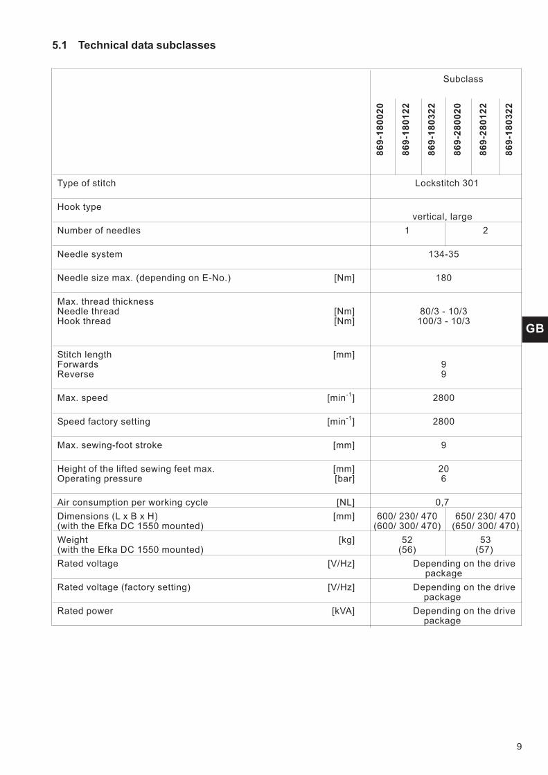
5.1 Technical data subclasses
Subclass
86
9-1
80
02
0
86
9-1
80
12
2
86
9-1
80
32
2
86
9-2
80
02
0
86
9-2
80
12
2
86
9-1
80
32
2
Type of stitch Lockstitch 301
Hook typevertical, large
Number of needles 1 2
Needle system 134-35
Needle size max. (depending on E-No.) [Nm] 180
Max. thread thicknessNeedle thread [Nm] 80/3 - 10/3Hook thread [Nm] 100/3 - 10/3
Stitch length [mm]Forwards 9Reverse 9
Max. speed [min-1] 2800
Speed factory setting [min-1] 2800
Max. sewing-foot stroke [mm] 9
Height of the lifted sewing feet max. [mm] 20Operating pressure [bar] 6
Air consumption per working cycle [NL] 0,7
Dimensions (L x B x H) [mm] 600/ 230/ 470 650/ 230/ 470(with the Efka DC 1550 mounted) (600/ 300/ 470) (650/ 300/ 470)
Weight [kg] 52 53(with the Efka DC 1550 mounted) (56) (57)
Rated voltage [V/Hz] Depending on the drivepackage
Rated voltage (factory setting) [V/Hz] Depending on the drivepackage
Rated power [kVA] Depending on the drivepackage

Threading scheme single-needle machine
Threading scheme double-needle machine
10
1
2
3
4
5
11
10
9
8
7
6
12
13
14
15
16
22
21
20
19
18
17

6. Operation
6.1 Threading the needle thread
Caution: Risk of injury!
Turn off the main switch!
The needle thread may only be threaded with the sewing machineswitched off.
Threading in the needle thread with single-needle machines
– Put the thread reel on the thread stand and lead the needle threadthrough the unwinder arm. The unwinder arm must be in vertical positionabove the thread reels.
– Thread in the thread through threading guide 1 and 2.– Pass the thread clockwise around the pre-tensioner wheel 3.– Pass the thread counter-clockwise around the supplementary tensioner
wheel 4.– Pass the thread clockwise around the around the main tensioner
wheel 5.– Pull the thread underneath the thread take-up spring 8 and pass it
through the thread regulator 10 to the thread lever 11.– Pass the thread through the thread lever 11 and the threading guides 9, 7
and 6 on the needle bar.– Thread the thread into the needle eye.
Threading in the needle thread with double-needle machines
– Put the thread reels on the thread stand and lead the needle thread andhook thread through the unwinder arm. The unwinder arm must be invertical position above the thread reels.
Thread for the left needle (as with single-needle machines)
– Thread in the thread through threading guide 1 and 2.– Pass the thread clockwise around the pre-tensioner wheel 3.– Pass the thread counter-clockwise around the supplementary tensioner
wheel 4.– Pass the thread clockwise around the around the main tensioner
wheel 5.– Pull the thread underneath the thread take-up spring 8 and pass it
through the thread regulator 10 to the thread lever 11.– Pass the thread through the thread lever 11 and the threading guides 9, 7
and 6 on the needle bar.– Thread the thread into the needle eye.
Thread for the right needle
– Thread in the thread through threading guide 12 and 13.– Pass the thread clockwise around the pre-tensioner wheel 14.– Pass the thread counter-clockwise around the supplementary tensioner
wheel 15.– Pass the thread clockwise around the around the main tensioner
wheel 16.– Pull the thread underneath the thread take-up spring 19 and pass it
through the thread regulator 21 to the thread lever 22.– Pass the thread through the thread lever 22 and the threading guides 20,
18 and 17 on the needle bar.– Thread the thread into the needle eye of the right needle.
GB
11

6.2 Adjusting the needle-thread tension
Pre-tension
When the main tensioner 2 and supplementary tensioner 3 are open,the needle thread must be under slight residual tension. This residualtension is produced by the pre-tensioner 1.
The pre-tensioner 1 simultaneously affects the length of the end of thesevered needle thread (the starting thread for the next seam).
– Basic setting:Turn knurled nut 4 until its front is flush with the bolt 5.
– To shorten the starting thread:Turn knurled nut 4 clockwise.
– To lengthen the starting thread:Turn knurled nut 4 counter-clockwise.
Main tension
The main tensioner 2 should be set to the minimum possible tension.
The interlacing of the threads must be in the center of the material.
With thin material excessive thread tension can cause unwantedgathering and thread breakage.
– Adjust the main tensioner 2 so that the stitches are uniform.
To increase tension - Turn the knurled nut clockwiseTo decrease tension - Turn the knurled nut counter-clockwise
Supplementary tension
The supplementary tensioner 3 is used for rapid change inneedle-thread tension during operation (e.g. with thickened seams).
– Set the supplementary tensioner 3 lower than the main tensioner 2.
12
3 2 1 5 4
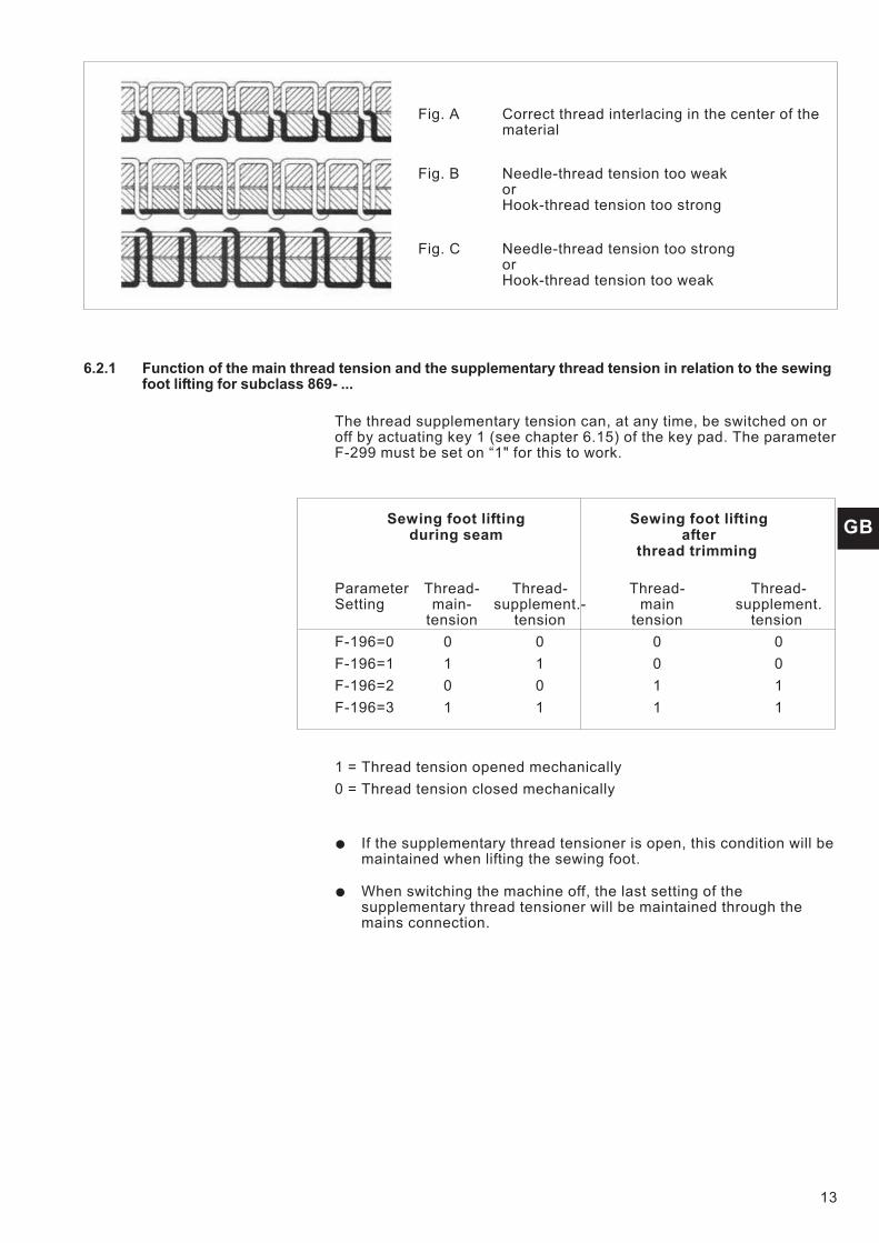
Fig. A Correct thread interlacing in the center of thematerial
Fig. B Needle-thread tension too weakorHook-thread tension too strong
Fig. C Needle-thread tension too strongorHook-thread tension too weak
6.2.1 Function of the main thread tension and the supplementary thread tension in relation to the sewingfoot lifting for subclass 869- ...
The thread supplementary tension can, at any time, be switched on oroff by actuating key 1 (see chapter 6.15) of the key pad. The parameterF-299 must be set on “1" for this to work.
Sewing foot lifting Sewing foot liftingduring seam after
thread trimming
Parameter Thread- Thread- Thread- Thread-Setting main- supplement.- main supplement.
tension tension tension tension
F-196=0 0 0 0 0
F-196=1 1 1 0 0
F-196=2 0 0 1 1
F-196=3 1 1 1 1
1 = Thread tension opened mechanically
0 = Thread tension closed mechanically
� If the supplementary thread tensioner is open, this condition will bemaintained when lifting the sewing foot.
� When switching the machine off, the last setting of thesupplementary thread tensioner will be maintained through themains connection.
GB
13

6.2.2 Function of supplementary thread tension in relation to the sewing foot lifting and the Speedomatfor subclass 869- ...
The thread supplementary tension can, at any time, be switched on oroff by actuating key 1 (see chapter 6.14) of the key pad. The parameterF-255 must be set on “7" for this to work.
Parameter Stroke adjustment max. Stroke adjustmentsSetting via knee switch setting wheel
Reaching of the HP-speedof parameter F-117
(Speedomat)
F-197 = 0 1 1
F-197 = 1 0 1
F-197 = 2 1 (*) 0
F-197 = 3 0 0
(*) If the stroke adjustment (max.) is switched on via the knee switchand the HP-speed (from parameter F-117) is reached through the“Speedomat”, then the supplementary thread tensioner will be switchedon automatically.
0 = Supplementary thread tension closed mechanically
1 = Supplementary thread tension opened mechanically
� If the supplementary thread tensioner is closed, this condition willbe maintained when adjusting the stroke.
� When switching the machine off, the last setting of thesupplementary thread tensioner will be maintained through themains connection.
Basic setting of the control unit for the automatic stepped reduction ofthe speed (Speedomat) through the setting wheel for the height of thealternating feed stroke
Parameter 188
Step 01-21 Entire Speedomat range
Step 01-10 max. allowed speed, ParameterF-111 = 3000 min-1
Step 11-18 Linear stepwise reduction of the max. speed(Speedomat)
Step 19-21 max. allowed speed, ParameterF-117 = 1.800 min-1
6.3 Opening the thread tension
Subclasses
869-180020, 869-280020
When lifting the sewing feet with the knee lever, the main andsupplementary tensioners are automatically opened.
Subclasses
869-180122, 869-180322, 869-280122, 869-280322
The needle thread tension is automatically opened when trimming thethread.
14
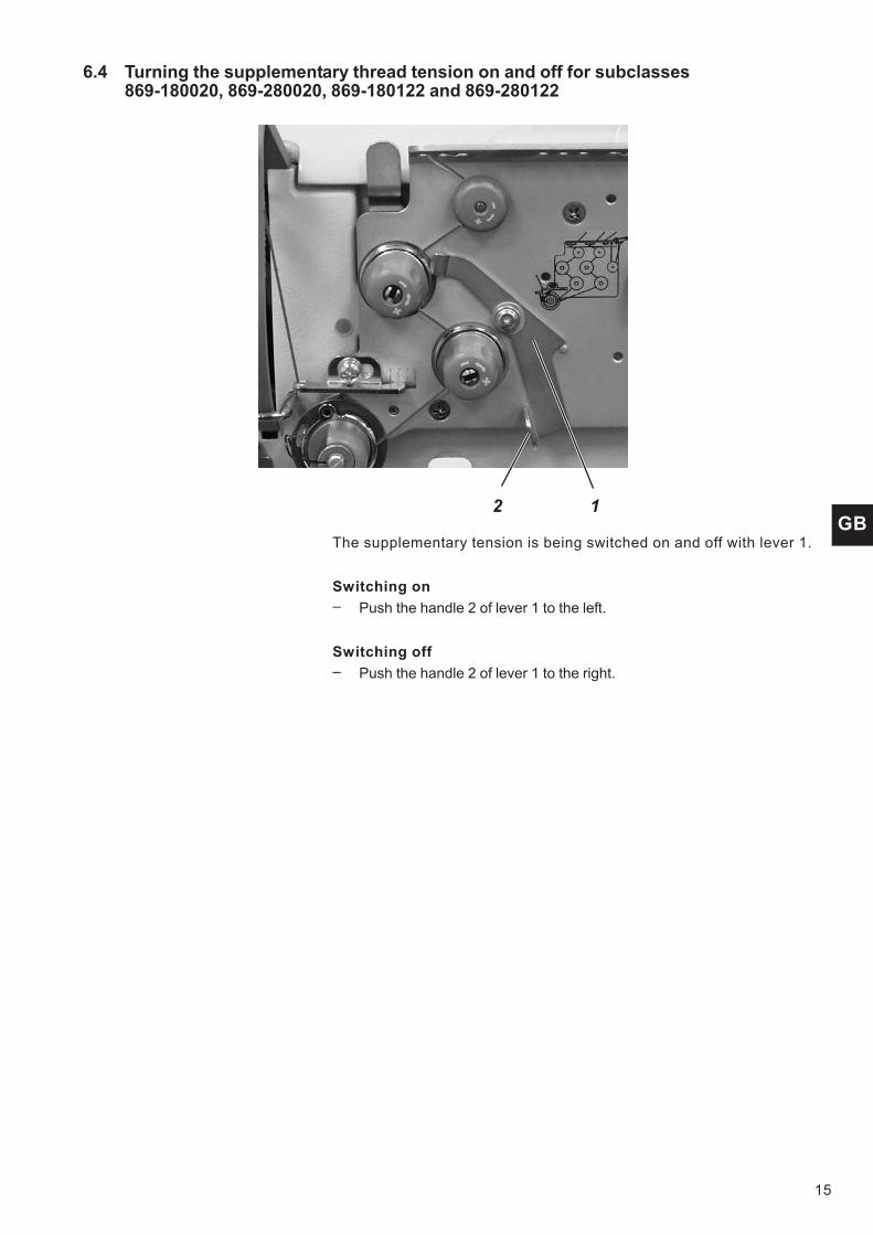
6.4 Turning the supplementary thread tension on and off for subclasses869-180020, 869-280020, 869-180122 and 869-280122
The supplementary tension is being switched on and off with lever 1.
Switching on
– Push the handle 2 of lever 1 to the left.
Switching off
– Push the handle 2 of lever 1 to the right.
15
GB2 1

6.5 Adjusting the thread regulator
Caution: Risk of injury!
Turn off the main switch.
The thread regulator may only be adjusted with the sewing machineswitched off.
The thread regulator 1 controls the quantity of needle thread requiredfor stitch formation.The thread regulator must be precisely adjusted for an optimum result.
At the correct setting the needle thread loop must be able slide withlow tension over the thickest point of the hook.
– Loosen the screw 2.
– Change the position of the thread regulator 1.Thread regulator to the left = more threadThread regulator to the right = less thread
– Fasten the screw 2.
Adjustment information:
If the maximum quantity of thread is required, the thread take-upspring 3 must be pulled upwards about 0.5 mm from its lower endposition. This is the case when the needle-thread loop passes themaximum hook diameter.
16
3 2 1

6.6 Winding on the hook thread
– Put the thread reel on the thread stand and lead the needle threadthrough the unwinder arm.
– Pull the thread through the thread guide 3, the tensioner 5 and the threadguide 3.
– Clamp the thread behind the blade 6 and tear it off.
– Fit the bobbin 1 on the bobbin winder.There is no need to wind the thread around the bobbin by hand.
– Press the bobbin-winder lever 2 into the bobbin.
– Sewing.The bobbin-winder lever terminates the process as soon as the bobbin isfull.The bobbin winder always stops in such a position that the blade 6 is inthe insertion position(see right-hand illustration)
– Remove the full bobbin 1, clamp the thread behind the blade 6 and tear itoff.
– Fit empty bobbin on the bobbin winder for the next winding process andpress the bobbin-winder lever 2 into the bobbin.
Attention: Danger of breakage!
If the thread is not to be wound on during sewing, it is essential for thesewing foot to be locked in the raised position and the sewing-footstroke set to the smallest value.
GB
17
5 4 3 2 1 2 6

6.7 Changing the hook-thread bobbin
Caution: Risk of injury!
Turn off the main switch.
The hook-thread bobbin may only be changed with the machineswitched off.
Remove the empty bobbin
– Slide the cover 1 sideways, raise up the flap 7 and remove the emptybobbin 2.
Insert a full bobbin
– Insert the bobbin 2 so that it moves in the opposite direction of the hookwhen unwinding.
– Pass the hook thread through the slit 3 and underneath the spring 4.
– Pull the hook thread through the slit 6 and continue pulling until it standsout about 3 cm.
– Close the flap 7 and pull the hook thread through the thread guide 5 ofthe flap.
18
1 2
6
5
4
7
2
3

6.8 Setting the hook thread tension
Caution: Risk of injury!
Turn the main switch off!
The hook thread tension may only be adjusted with the sewingmachine switched off.
Setting the tension spring 2
– Set the tension spring 2 by turning the adjustment screw 1.Increase the hook thread tension =Turn screw 1 clockwise
Decrease the hook thread tension =Turn screw 1 counter-clockwise.
19
GB
1
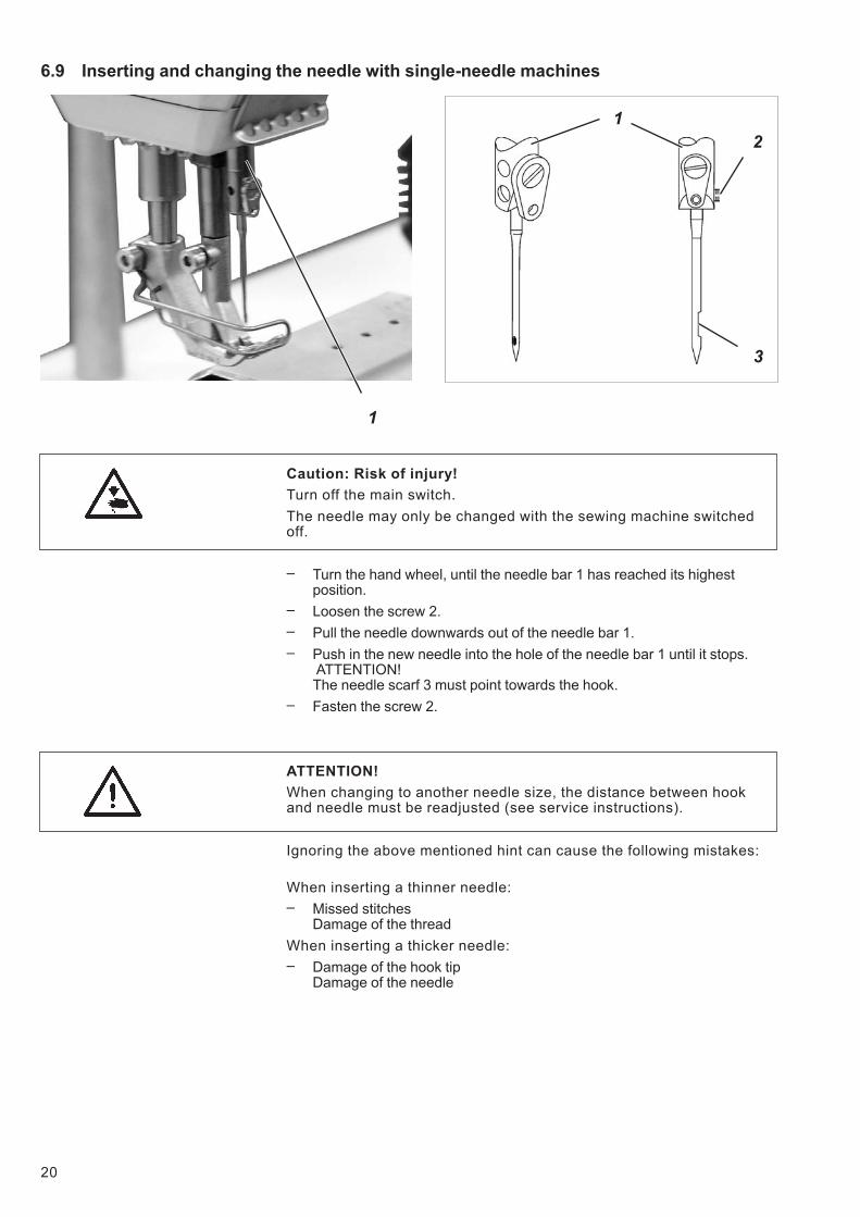
6.9 Inserting and changing the needle with single-needle machines
Caution: Risk of injury!
Turn off the main switch.
The needle may only be changed with the sewing machine switchedoff.
– Turn the hand wheel, until the needle bar 1 has reached its highestposition.
– Loosen the screw 2.
– Pull the needle downwards out of the needle bar 1.
– Push in the new needle into the hole of the needle bar 1 until it stops.ATTENTION!The needle scarf 3 must point towards the hook.
– Fasten the screw 2.
ATTENTION!
When changing to another needle size, the distance between hookand needle must be readjusted (see service instructions).
Ignoring the above mentioned hint can cause the following mistakes:
When inserting a thinner needle:
– Missed stitchesDamage of the thread
When inserting a thicker needle:
– Damage of the hook tipDamage of the needle
20
1
1
3
2

6.10 Inserting and changing the needle with double-needle machines
Caution: Risk of injury!
Turn the main switch off!
The needle may only be changed with the sewing machine switchedoff.
– Turn the hand wheel, until the needle bar 1 has reached its highestposition.
– Loosen the screw 3.
– Pull the needle downwards out of the needle holder 2.
– Push in the new needle into the hole of the needle holder 2 until it stops.ATTENTION!Seen from the operator’s side, the needle scarf 4 of the right needle mustpoint to the right side and the needle scarf of the left needle point to theleft side (see drawing).
– Fasten the screw 3.
ATTENTION!
When changing to another needle size, the distance between hookand needle must be readjusted (see service instructions).
Ignoring the above mentioned hint can cause the following mistakes:
When inserting a thinner needle:
– Missed stitchesDamage of the thread
When inserting a thicker needle:
– Damage of the hook tipDamage of the needles
21
GB
2 1
1
2
3
4

6.11 Lifting the sewing foot
Subclass
869-180020, 869-280020
The sewing feet can be lifted mechanically by actuating the kneelever 1.
Subclasses
869-180112, 869-180322, 869-280122, 869-280322
The sewing feet can be lifted electro-pneumatically by actuating thepedale 2 or the knee lever 1.
Mechanical sewing foot lifting (Knee lever)
– To adjust the position of the material (e.g. for corrective purposes), pushthe knee lever 1 (optional) to the right.The sewing foot remains in the raised position as long as pressure ismaintained on the knee lever 1.
Raising the sewing foot electro-pneumatically (pedal)
– Press the pedal 2 half-way back.The sewing feet are raised with the machine at a halt.
– Press the pedal 2 all the way back.The thread trimmer is activated and the sewing foot raised.
22
1 2

6.12 Locking the sewing feet in lifted position
– Push the lever 1 downwards.The sewing feet are locked in lifted position.
– Push the lever 1 upwards.The sewing feet are released.
or
– Lift the sewing feet pneumatically or by pushing the knee lever.The lever 1 then moves back into its initial position.
6.13 Sewing foot pressure
The required sewing-foot pressure is set with the setting wheel 2.
ATTENTION!
The material must not “swim”.
Do not set a higher pressure than is necessary.
– To increase the sewing-foot pressure = Turn the setting wheel 2clockwise.
– To decrease the sewing-foot pressure = Turn the setting wheel 2counter-clockwise.
GB
23
1 1 2

6.14 Sewing-foot stroke
The special sewing machine 869 has, depending on the subclass, asstandard equipment two setting wheels for the sewing foot stroke. Withthe left setting wheel 2 the standard sewing foot stroke from 1 to 9 mmis selected.
With the right setting wheel 1 an increased sewing foot stroke from 1 to9 mm is selected.
– Turning the setting wheel 1 and 2 (1 to 9)1 = minimal sewing foot stroke9 = maximal sewing foot stroke
Automatic limiting of the speed
Machines without thread trimmer
With these machines the speed is not controlledPlease take into consideration the hint and the chart on the next side.
Machines with thread trimmer
The sewing-foot stroke and the speed are interdependent. Apotentiometer is linked mechanically with the adjusting wheel. Bymeans of this potentiometer the control unit detects what foot-strokehas been set and restricts the speed of rotation accordingly.
Machines with electro-pneumatic rapid stroke adjustment
With fabric parts that are thicker or in order to sew over cross seams,the increased sewing foot stroke (setting wheel 1) can be switched onduring the sewing process by actuating the knee switch 3 beneath thetable top.As with the machines that are equipped with a thread trimmer, thepotentiometer is also available.
ATTENTION! Danger of breakage!
The standard sewing foot stroke that is set with the setting wheel 2may never exceed the stroke set with the setting wheel 1.
24
2 1 3

Operation mode of the quick stroke adjustment
The activation period of the maximum sewing foot stroke depends onthe set operation mode. It is possible to choose between threeoperation modes.The individual operation modes are determined by the setting of theparameters F-138 and F-184 at the control panel (see enclosedinstructions of the motor manufacturer).
Operation mode Operation / Explanation
KeystrokeF-138 = 0F-184 = 0
The maximum sewing foot stroke remains activated aslong as the knee switch 3 is actuated.
Push-lockF-138 = 1
The maximum sewing foot stroke is activated byactuating the knee switch 3.By actuating the knee switch once again the maximumsewing foot stroke is deactivated.
Keystrokewith lowestspeedF-138 = 0F-184 0 < 100
The maximum sewing foot stroke remains activated aslong as knee switch 3 is actuated.After releasing the knee switch the machine sews withthe maximum sewing foot stroke until the set minimumnumber of stitches is reached (parameter F-184).Afterwards, the seam is continued with normal sewingfoot stroke.
Please note!
The switch 4 on the rear of the knee switch 3 can also be used toswitch between the “keystroke” and “push-lock” operation modes.
Hint!
In order to ensure an operation as safe as possible and a highdurability, the max. speed as shown in the chart should not beenexceeded.
Subclass Stitch length range Sewing-foot stroke max. SpeedSetting wheel position [mm] [min
-1]
869-180020 0-6 1-3 2800
869-180112 4 2500
869-180322 5 2100
869-280020 6-9 1800
869-280122
869-280322 1-4 2900
6-9 5 2100
6-9 1800
GB
25
4
3

6.15 Setting the stitch length
The special sewing machine 869 has, depending on the subclass, asstandard equipment two setting wheels. Thus, two different stitchlengths can be sewn, that are activated by actuating the key 4 (seechapter 6.15).
The two stitch lengths are set with the setting wheels 1 and 2 on themachine arm.
– Set the higher stitch length with the upper setting wheel 1.Setting 1 = min. stitch lengthSetting 9 = max. stitch length
– Set the smaller stitch length with the lower setting wheel 2.Setting 1 = min. stitch lengthSetting 9 = max. stitch length
The stitch length are the same for both, forward and backward sewing.
– For the manual sewing of tacks, push the stitch regulator lever 3downwards.The machine sews backward as long as the stitch regulator lever 3 ispressed down.
Please note:
In order to facilitate the setting of stitch lengths, the stitch length thatremains unchanged should be activated with key 2 (see chapter 6.15).
ATTENTION! Danger of breakage!
The stitch length set with the lower setting wheel 2 must not exceedthe stitch length set with the upper setting wheel 1.
26
3 2 14

6.16 Key pad on the machine arm
Key Function
1 Supplementary tread tensionButton is back-lit: the supplementary thread tension isactivated.Button is not back-lit: the supplementary threadtension is not activated.
2 2nd stitch lengthButton is back-lit: long stitch length (upper settingwheel) is activatedButton is not back-lit: small stitch length (lower settingwheel) is activated
3 Recalling or suppressing the initial or final bartack.If the initial and final bartacks are activated, then thenext bartack is deactivated when the button ispressed.If the initial and final bartacks are not activated, thenthe next bartack is activated when the button ispressed.
4 Move the needle to the upper or lower position.The function of the button can be set with theparameter F-242.1 = needle up/down2 = needle up3 = single stitch4 = full stitch5 = needle to position 2The factory setting is 1 (needle up/down).
5 Manually sewing backward.The machine sews backwards for as long as thebutton is held down.
GB
27
6 5 4 3 2 1
8
7

Key Function
8 LED display “Power On”
The function of key 7 can be selected with the screw 6 under the keys.
– Selecting a function.Example: 6 = Manually sewing backward.
– Turn in the screw 6 under the key 5 and turn it 90° to the right (the slotstands vertically).The function can now be called via both keys 5 and 7.
ATTENTION!
Before key 7 can be programmed with a new function, the formersetting must be deactivated.
7. Sewing
7.1 Sewing with machines using the FIR clutch positioning drive
For a detailed description of the control unit, please consult theenclosed current issue of the operating manual of the motormanufacturer (see also www.efka.net).
With pedal
0 At rest
1 Sewing forwards with minimum speed
2 Sewing forwards with higher speed
: : :
3 Sewing forwards with maximum speed
28
01
2
3

7.2 Sewing with machines using the Efka DC1550/DA321G positioning drive
The control unit DA321G contains all required operational interfacesfor switching functions and setting parameters.
It is possible to operate without an operating panel, but the seamprogramming cannot be carried out.
The V810 and V820 operating panels can also be connected to thecontrol unit.
They are deliverable as optional equipment.Seam programming can beperformed with the V820 operating panel.
For a detailed description of the control unit, please consult theenclosed current issue of the operating manual “Efka DC1550 -DA321G” of the motor manufacturer (see also www.efka.net).
D
With pedal
The pedal position is detected using a sampling detector with 16different levels.
Their meanings are listed in the table below:
Pedal position Pedal movement Meaning
-2 Completely backwards Command for cutting the thread (end of seam)
-1 Half backwards Command for raising the sewing foot
0 Rest position see remark below
1 Slightly forwards Command for lowering the sewing foot
2 More forwards Sew with miminal speed (first step)
3 More forwards Sew with more speed (second step)
: : :
13 Entirely forwards Sew with maximal speed (12th step)
Remark
The following functions can be programmed to correspond with the restposition:
– Needle position (down/up) and sewing-foot position (down/up) when stopin seam.
– Sewing-foot position (up/down) after end of seam. (Pedal fullybackwards, then in rest position)
29
GB

Sewing process Operation / Explanation
Prior to sewing
Starting position
Position material at seam start
- Pedal is in the resting position.The sewing machine is at rest.The needle is up.The sewing feet are down.
- Move pedal back halfway.Raise the sewing feet.
- Push the material to the needle.
Sewing - Step the pedal forward and hold.The machine then continues to sew with the speeddetermined by the pedal.
In mid-seam
Interrupt the sewing process
Resume the sewing process(after releasing the pedal)
- Release pedal (rest position).The machine stops in the first position(needle down).The sewing feet are down.
- Step forward on the pedal.The machine then continues to sew with the speeddetermined by the pedal.
Sewing an intermediate bartack - Press the stitch regulator lever 4 downwards.The machine sews in reverse as long as thestitch regulator lever is pressed.The speed is determined by the pedal.
or
- Press the button 3.
30
3 2 1 4
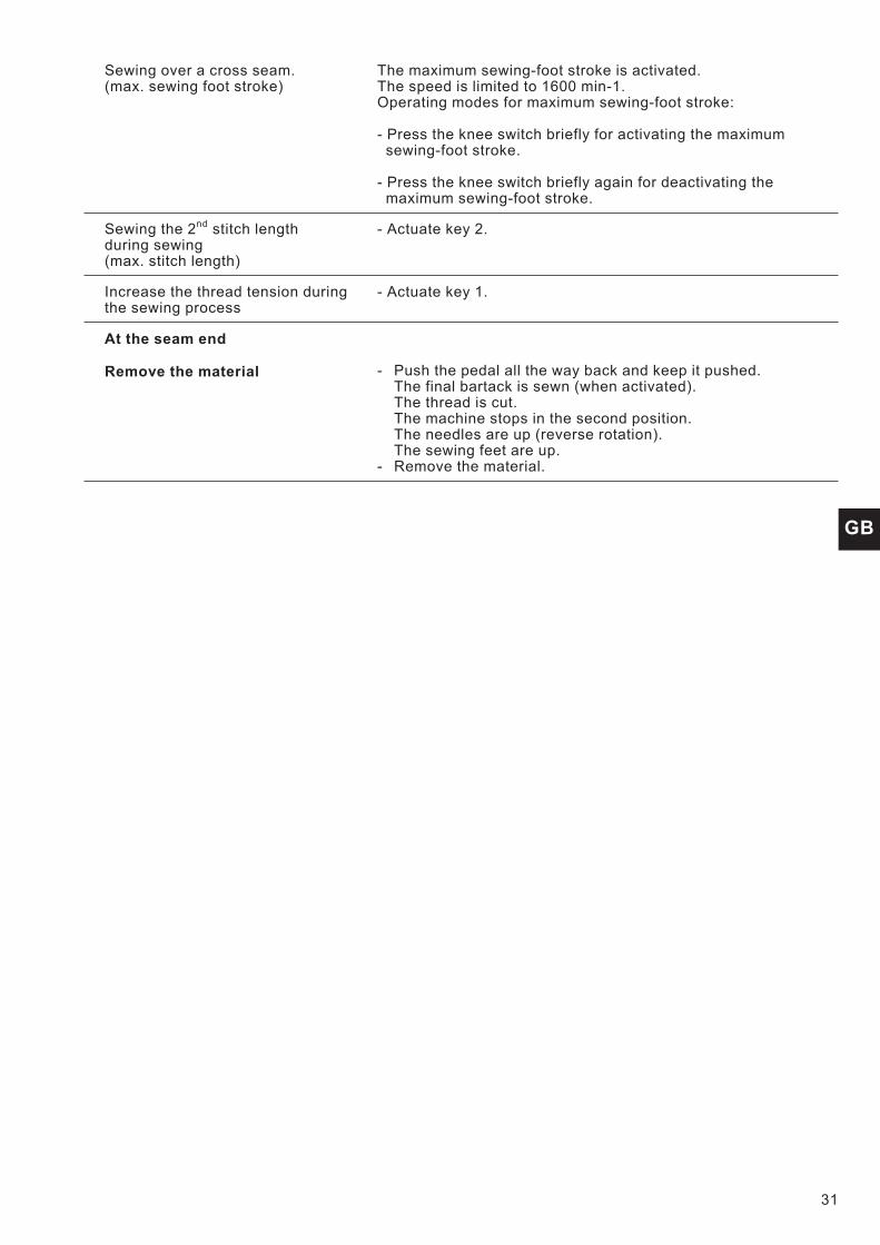
Sewing over a cross seam.(max. sewing foot stroke)
The maximum sewing-foot stroke is activated.The speed is limited to 1600 min-1.Operating modes for maximum sewing-foot stroke:
- Press the knee switch briefly for activating the maximumsewing-foot stroke.
- Press the knee switch briefly again for deactivating themaximum sewing-foot stroke.
Sewing the 2nd stitch lengthduring sewing(max. stitch length)
- Actuate key 2.
Increase the thread tension duringthe sewing process
- Actuate key 1.
At the seam end
Remove the material - Push the pedal all the way back and keep it pushed.The final bartack is sewn (when activated).The thread is cut.The machine stops in the second position.The needles are up (reverse rotation).The sewing feet are up.
- Remove the material.
31
GB

8. Tilting Back the Machine Head
Caution Crushing Hazard!
Do not reach between the base and the machine arm while tilting backthe machine head.
Tilting back the machine head
– Pull lever 1 upwards.The locking mechanism is then released.
– Tilt the machine head 2 cautiously to the rear.
Re-closing the machine head
– Tilt the machine head 2 forwards.The head tilts back to the position shown in the illustration below.
– Pull lever 1 upwards and cautiously tilt the head downwards.
Attention !
Only tilt the machine head up for a short period (for example formaintenance work).If the machine head is tilted back for a longer period (for a night orweekend), oil can leak out in the hook area.
32
1 2
1

9. Folding Down the Table Top with the MG 56-2 Stand
Caution: Risk of injury!
Always hold the table top with both hands when pulling it out.
– Loosen the table top latch 1 located under the table top.
– Pull out the table top 2 to the left and fold out.
– Hook in the diagonal brace 4 to the bolts 3.
– Fold down the table top
– Follow these steps in the opposite order to raise the table top.
33
GB
2 1
4 3

10. Maintenance
10.1 Cleaning and Checking
Caution: Risk of injury!
Turn the main switch off!Maintenance may only be carried out with the machine switched off!
Maintenance work must be carried out no less frequently than at theintervals given in the tables (see “operating hours” column).
Maintenance intervals may need to be shorter when processingheavy-shedding materials.
A clean machine is a trouble-free machine.
Maintenance work Explanation Operatingto be carried out hours
Machine head
- Remove lint, pieces ofthread(e.g. with an air blow gun)
Places in special need of cleaning:- area under the throat plate 2- area around the hook 1- bobbin housing- thread trimmer- needle area
8
Direct drive
Clean fan grille 3. (e.g. withan air blow gun)
Remove lint and pieces of thread fromair-intake openings.
8
34
32 1
GB
35
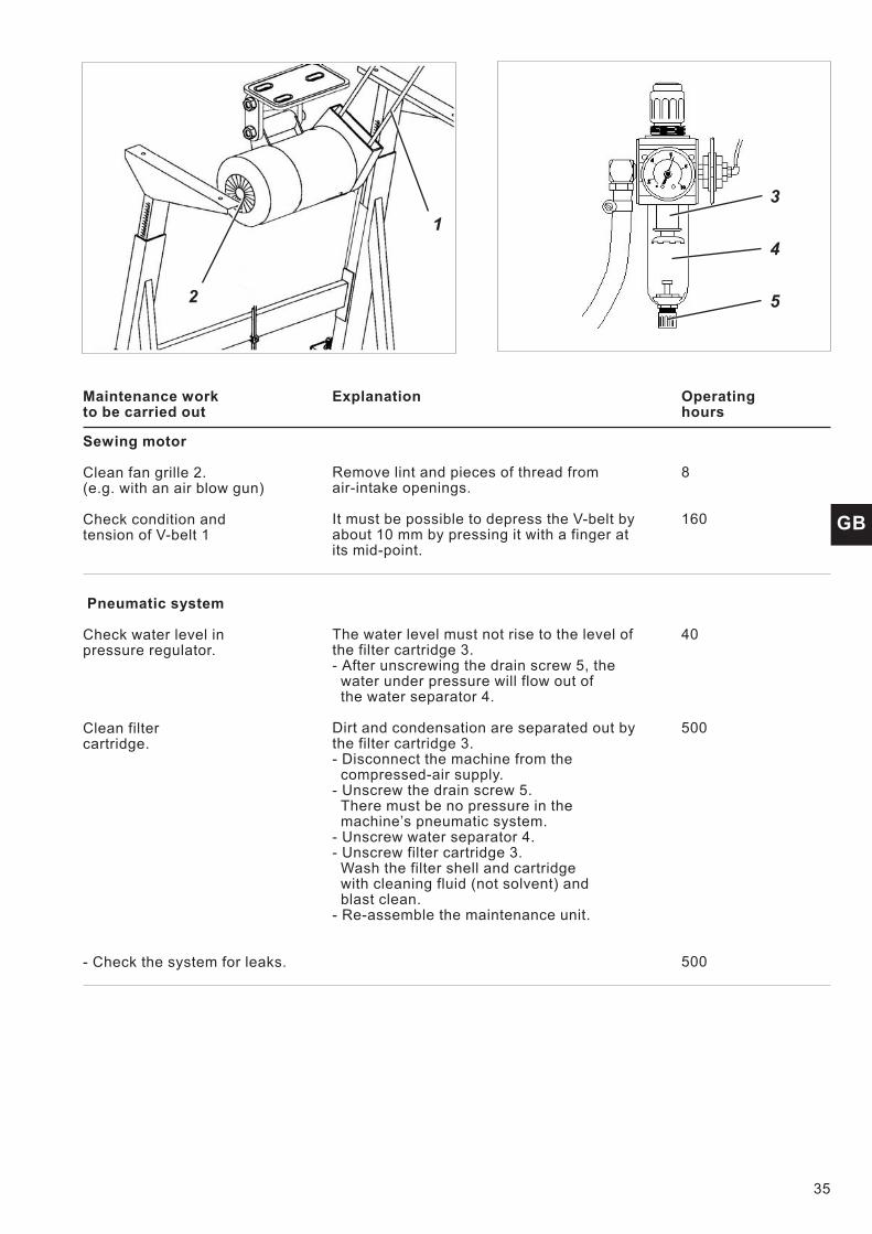
Maintenance work Explanation Operatingto be carried out hours
Sewing motor
Clean fan grille 2.(e.g. with an air blow gun)
Check condition andtension of V-belt 1
Remove lint and pieces of thread fromair-intake openings.
It must be possible to depress the V-belt byabout 10 mm by pressing it with a finger atits mid-point.
8
160
Pneumatic system
Check water level inpressure regulator.
Clean filtercartridge.
- Check the system for leaks.
The water level must not rise to the level ofthe filter cartridge 3.- After unscrewing the drain screw 5, the
water under pressure will flow out ofthe water separator 4.
Dirt and condensation are separated out bythe filter cartridge 3.- Disconnect the machine from the
compressed-air supply.- Unscrew the drain screw 5.
There must be no pressure in themachine’s pneumatic system.
- Unscrew water separator 4.- Unscrew filter cartridge 3.
Wash the filter shell and cartridgewith cleaning fluid (not solvent) andblast clean.
- Re-assemble the maintenance unit.
40
500
500
1
2
3
4
5

10.2 Oil Lubrication
Caution: Risk of injury!
Oil can cause skin eruptions.Avoid protracted contact with the skin.In the event of contact, thoroughly wash the affected area.
ATTENTION!
The handling and disposal of mineral oils is subject to legal regulation.Deliver used oil to an authorised collection point.Protect your environment.Take care not to spill oil.
To lubricate the special sewing machine use only DA-10 lubricating oilor an equivalent oil of the following specification:
– Viscosity at 40° C: 10 mm2/s
– Flashpoint: 150° C
DA-10 is available from DÜRKOPP ADLER AG retail outlets under thefollowing part numbers:
250-ml container: 9047 0000111-litre container: 9047 0000122-litre container: 9047 0000135-litre container: 9047 000014
Maintenance work Explanation Operatingto be carried out hours
Lubrication of the machinehead
The head is equipped with centralized oil wicklubrication. The bearings are supplied by theoil reservoir 1.
- The oil level must not dropbelow the mark 3 on the oil reservoir.
The oil reservoir illuminates when the oillevel falls below the mark 3. (Only forsubclass 869-180322, 869-280322)
- Refill oil through the hole 2 until it reachesthe “Max” mark.
8
36
1