Speed Controller with Indicator (In-line Type) 10-AS-FS Series
5
200 06 1 Caution Be sure to read this before handling the products. Refer to the back cover for safety instructions. For flow control equipment precautions, refer to the “Handling Precautions for SMC Products” and the “Operation Manual” on the SMC website: http://www.smcworld.com Flow Direction Symbol on Body Model Flow Rate and Sonic Conductance Specifications ∗ C and b values are for controlled flow with the needle fully open and free flow with the needle fully closed. ∗ The same specifications also apply to the 10-AS-FSG series (stainless steel type). Model 10-AS1002FS 10-AS2002FS 10-AS2052FS 10-AS3002FS 10-AS4002FS Tubing O.D. Metric size ø3.2 ø4 ø6 ø4 ø6 ø6 ø8 ø6 ø8 ø10 ø12 ø10 ø12 Inch size ø1/8" ø5/32" ø1/4" ø5/32" ø1/4" ø1/4" ø5/16" ø1/4" ø5/16" ø3/8" — ø3/8" ø1/2" C values: Sonic conductance dm 3 /(s·bar) Free flow 0.3 0.4 0.6 0.4 0.6 1.0 1.2 1.1 1.6 2.2 2.6 2.4 3.5 Controlled flow 0.3 0.4 0.6 1.0 1.2 1.3 1.9 2.7 3.3 2.8 4.1 b values: Critical pressure ratio Free flow 0.3 0.2 0.3 0.1 0.2 0.2 0.3 0.2 Controlled flow 0.2 0.3 0.4 0.2 0.2 0.3 0.1 0.2 0.1 0.2 Model Applicable tubing O.D. Metric size Inch size 3.2 4 6 8 10 12 1/8" 5/32" 1/4" 5/16" 3/8" 1/2" 10-AS1002FS V V V V V V 10-AS2002FS V V V V 10-AS2052FS V V V V 10-AS3002FS V V V V V V V 10-AS4002FS V V V V Symbol ∗1 Use caution at the max. operating pressure when using soft nylon or polyurethane tubing. (Refer to the Web Catalog for details.) Fluid Air Proof pressure 1.5 MPa Max. operating pressure 1 MPa Min. operating pressure 0.1 MPa Ambient and fluid temperatures −5 to 60°C (No freezing) Applicable tubing material Nylon, Soft nylon, Polyurethane ∗1 , FEP, PFA Grease Fluorine grease Cleanliness class (ISO class) Class 5 2 F Indicator window direction With One-touch fittings With indicator How to Order Body size 100 M5 standard 200 1/8 standard 205 1/4 standard 300 3/8 standard 400 1/2 standard Nil 0° Indicator window Index plate 2 90° Index plate 1 180° Indicator window Index plate 3 270° Indicator window Index plate S Applicable tubing O.D. ∗1 Metric size Inch size 01 ø1/8" 03 ø5/32" 07 ø1/4" 09 ø5/16" 11 ø3/8" 13 ø1/2" 23 ø3.2 ∗2 04 ø4 06 ø6 08 ø8 10 ø10 12 ø12 ∗1 For selecting applicable tubing O.D., refer to the “Model” shown above. ∗2 Use ø1/8" tubing. AS 10 3 Speed Controller with Indicator (In-line Type) 10-AS-FS Series RoHS A
Transcript of Speed Controller with Indicator (In-line Type) 10-AS-FS Series

200 061
Caution
Be sure to read this before handling the products.Refer to the back cover for safety instructions. For flow control equipment precautions, refer to the “Handling Precautions for SMC Products” and the “Operation Manual” on the SMC website: http://www.smcworld.com
Flow DirectionSymbol on Body
Model
Flow Rate and Sonic Conductance
Specifications
∗ C and b values are for controlled flow with the needle fully open and free flow with the needle fully closed.∗ The same specifications also apply to the 10-AS-FSG series (stainless steel type).
Model 10-AS1002FS 10-AS2002FS 10-AS2052FS 10-AS3002FS 10-AS4002FS
TubingO.D.
Metric size ø3.2 ø4 ø6 ø4 ø6 ø6 ø8 ø6 ø8 ø10 ø12 ø10 ø12
Inch size ø1/8" ø5/32" ø1/4" ø5/32" ø1/4" ø1/4" ø5/16" ø1/4" ø5/16" ø3/8" — ø3/8" ø1/2"
C values: Sonicconductancedm3/(s·bar)
Free flow 0.3 0.4 0.6 0.4 0.6 1.0 1.2 1.1 1.6 2.2 2.6 2.4 3.5Controlled
flow 0.3 0.4 0.6 1.0 1.2 1.3 1.9 2.7 3.3 2.8 4.1
b values: Criticalpressure ratio
Free flow 0.3 0.2 0.3 0.1 0.2 0.2 0.3 0.2Controlled flow 0.2 0.3 0.4 0.2 0.2 0.3 0.1 0.2 0.1 0.2
ModelApplicable tubing O.D.
Metric size Inch size3.2 4 6 8 10 12 1/8" 5/32" 1/4" 5/16" 3/8" 1/2"
10-AS1002FS V V V V V V
10-AS2002FS V V V V
10-AS2052FS V V V V
10-AS3002FS V V V V V V V
10-AS4002FS V V V V
Symbol
∗1 Use caution at the max. operating pressure when using soft nylon or polyurethane tubing. (Refer to the Web Catalog for details.)
Fluid AirProof pressure 1.5 MPaMax. operating pressure 1 MPaMin. operating pressure 0.1 MPaAmbient and fluid temperatures −5 to 60°C (No freezing)Applicable tubing material Nylon, Soft nylon, Polyurethane∗1, FEP, PFAGrease Fluorine greaseCleanliness class (ISO class) Class 5
2 F
Indicator window direction
With One-touch fittings
With indicator
How to Order
Body size100 M5 standard200 1/8 standard205 1/4 standard300 3/8 standard400 1/2 standard
Nil 0°
Indicator window
Index plate 2 90° Index plate
1 180°
Indicator window
Index plate 3 270°
Indicator window
Index plate
S
Applicable tubing O.D.∗1
Metric size Inch size01 ø1/8"03 ø5/32"07 ø1/4"09 ø5/16"11 ø3/8"13 ø1/2"
23 ø3.2∗2
04 ø406 ø608 ø810 ø1012 ø12
∗1 For selecting applicable tubing O.D., refer to the “Model” shown above.
∗2 Use ø1/8" tubing.
AS10
3
Speed Controller with Indicator(In-line Type)
10-AS-FS Series RoHS
A

e L-bracket
r Threaded stud kit for manifold
Adapter for manifold mounting∗
Options
eL-Bracket
rThreaded Stud Kit for Manifold
Details of Threaded Stud Kit for Manifold
∗ 10-AS4002FS type can be mounted with the threaded stud kit only (Adapter for manifold mounting is not required).
∗ It is included in the threaded stud kit for manifold (excluding the 10-AS4002FS). Refer to the details of the kit shown on the left.
wDIN Rail Mounting Bracket
Part no.Adapter for manifold mounting Threaded stud Accessories
Part no. Quantity Length Quantity Hexagon nut Quantity Flat washer QuantityAS-1AB
AS-10A
372 2
M3 4 M3 4
AS-2AB 90 2AS-3AB
5104 2
AS-4AB 114 2AS-5AB
7135 2
AS-6AB 143 2AS-7AB
9167 2
AS-8AB 170 2AS-23AB 180 2AS-9AB
AS-20A
3 90 2AS-10AB 5 135 2AS-11AB 7 180 2AS-12AB 9 220 2AS-13AB
AS-25A
3 111 2
M4 4 M4 4
AS-14AB 5 147 2AS-15AB 7 191 2AS-16AB 9 236 2AS-17AB
AS-30A
3 111 2AS-24AB 3 119 2AS-19AB 5 179 2AS-20AB 7 236 2AS-21AB 9 258 2AS-22AB 9 277 2AS-25AB 9 293 2AS-43B
—
119 2AS-45B 179 2AS-47B 236 2AS-48B 277 2
Part number Applicable model4 stations 6 stations 8 stations 10 stations Metric size Inch size
AS-1AB AS-3AB AS-5AB AS-7AB 10-AS1002FS-23 10-AS1002FS-0110-AS1002FS-04 10-AS1002FS-03
AS-4AB AS-6AB AS-8AB 10-AS1002FS-06 —AS-2AB AS-23AB — 10-AS1002FS-07
AS-9AB AS-10AB AS-11AB AS-12AB10-AS2002FS-04 10-AS2002FS-0310-AS2002FS-06 —
— 10-AS2002FS-07
AS-13AB AS-14AB AS-15AB AS-16AB10-AS2052FS-06 —
— 10-AS2052FS-0710-AS2052FS-08 10-AS2052FS-09
AS-17AB AS-19AB AS-20AB AS-22AB
10-AS3002FS-06 —— 10-AS3002FS-07
10-AS3002FS-08 10-AS3002FS-0910-AS3002FS-10 —
— 10-AS3002FS-11AS-24AB AS-25AB 10-AS3002FS-12 —
AS-43B AS-45B AS-47B AS-48B
10-AS4002FS-10 —— 10-AS4002FS-11
10-AS4002FS-12 —— 10-AS4002FS-13
Part no. Applicable modelAS-10D 10-AS1002FSAS-20D 10-AS2002FSAS-25D 10-AS2052FSAS-30D 10-AS3002FSAS-40D 10-AS4002FS
Part no. Applicable modelAS-10L 10-AS1002FSAS-20L 10-AS2002FSAS-25L 10-AS2052FSAS-30L 10-AS3002FSAS-40L 10-AS4002FS
Part no. Applicable modelAS-10A1 10-AS1002FSAS-20A1 10-AS2002FSAS-25A1 10-AS2052FSAS-30A1 10-AS3002FS
∗1 Prepare DIN rail by user.∗2 It is included in the threaded stud kit for manifold (excluding the 10-AS4002FS). Refer to the following details of the kit.
e L-bracket
r Threaded stud kit for manifold
Adapter for manifold mounting∗2
r Threaded stud kitfor manifold
Adapter for manifold mounting∗2
w DIN rail mounting bracket DIN rail∗1
Mounting screw∗1
Mounting surface
q Adapter for direct mounting
Ex.) 10-AS2002FS-06When connecting 4 pcs. and mounting L-brackets on both sides
¡Speed controller 10-AS2002FS-06 4 pcs.
¡L-bracket AS-20L 2 pcs.
¡Threaded stud kit for manifold AS-9AB 1 set(Adapter for manifold mounting is included.)
Ordering ExampleThreaded studs for manifold are not included when L-bracket and DIN rail mounting bracket are ordered. Please order them according to the number of stations.
∗1 Prepare a mounting screw by user.
qAdapter for Direct Mounting∗ For use when the mounting surface interferes with the bonnet.
∗ The 10-AS4002FS can be mounted without the adapter.
4
Speed Controller with Indicator (In-line Type) 10-AS-FS Series
A
Inlet pressure: 0.5 MPa
06, 0
7
200
100
00 5 10
Flo
w r
ate
[L/m
in(A
NR
)]Number of needle rotations
03, 04
Inlet pressure: 0.5 MPa500
400
300
200
100
00 5 10
Flo
w r
ate
[L/m
in(A
NR
)]
Number of needle rotations
06, 07
08, 09
Inlet pressure: 0.5 MPa1000
500
00 5 10
Flo
w r
ate
[L/m
in(A
NR
)]
Number of needle rotations
10, 1
1, 1
2
06, 07
08, 09
Inlet pressure: 0.5 MPa1500
1000
500
00 5 10
Flo
w r
ate
[L/m
in(A
NR
)]
Number of needle rotations
12, 1
310, 1
1
q
qwe
!1
t
!5
!3
!6
we r !2 !4
u qo !0i yqo !0i y
t
!1
!5
!3
!6
we r !2 !4
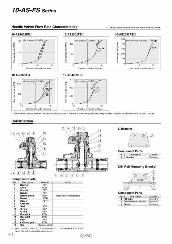
Needle Valve: Flow Rate Characteristics
Inlet pressure: 0.5 MPa100
50
00 5 10
Flo
w r
ate
[L/m
in(A
NR
)]
Number of needle rotations
01, 2
3, 0
3, 0
4, 0
6, 0
7
10-AS1002FS 10-AS2002FS
Construction
∗ The flow rate characteristics are representative values.
∗ The numbers above the flow rate characteristic curves in the charts show the applicable tubing outside diameter as defined by the product number.
10-AS2052FS
10-AS3002FS 10-AS4002FS
Component PartsNo. Description Material Note1 Body A PBT2 Knob POM3 Body B PBT4 Needle PBT5 Needle guide Brass Electroless nickel plating6 U-seal HNBR7 Spacer PBT∗1
8 Cassette —9 Seal NBR10 O-ring NBR11 O-ring NBR12 Bonnet A POM13 Bonnet B POM14 Gear PPS15 Indicator gear POM16 Clip Stainless steel
∗1 The 10-AS3002FS-11, 10-AS4002FS-11, 10-AS4002FS-13 are made of electroless nickel plated brass.
Component Parts
Component PartsNo. Description Material1 Bracket Steel strip2 Cross recessed round head screw Steel wire3 Clasp Steel strip
No. Description Material1 Bracket Steel strip
L-Bracket
DIN Rail Mounting Bracket
5
10-AS-FS Series
A

Y
XøX
øD4
L8
L7
L6 X1
L4
L3
L2
L1
M1M1
øD
1
W2
2 x Applicable tubing O.D. ød
øD3
L5
øD5øD2 through
X2
W1
Dimensions
Inch Size
∗1 Reference dimensions
ModelApplicable
tubingO.D. ød
D1
Release button D2 D3 D4 D5 L1 L2 L3
L4∗1L5 L6 L7 L8 M1 W1 W2 X1 X2
Weight[g]
øX(X) Y Max. Min.10-AS1002FS-01 1/8" 8.4 6.7 9.5
3.3 5.5 9.4 1036.6
5.1 11.8 36.4 33.911 15.4 8.8
10.1 13.5 13.6 15.1 5.5 9.6
5.210-AS1002FS-03 5/32" 9.3 7.7 10 37.6 5.510-AS1002FS-07 1/4" 12 10.9 — 40.1 6.2 12.9 37.5 35 12.8 6.710-AS2002FS-03 5/32" 9.3 7.7 10
3.3 5.5 12 1241.3 6.3 13.4 44.5 43
12.6 17 10.512.3
13.5 20 21.5 6.5 159.5
10-AS2002FS-07 1/4" 12 10.9 — 43.2 6.5 13.6 44.7 43.2 12.8 10.610-AS2052FS-07 1/4" 13.2 12 —
4.3 7.8 13 1653.4 7.6 17.2 49 47.6
17 22.5 12 16.1 17
21.5 24 7.8 16.216.4
10-AS2052FS-09 5/16" 15.2 13.5 — 57.2 8.5 18.1 49.9 48.5 19 18.410-AS3002FS-07 1/4" 13.2 12 —
4.5 8 16.6 2059
9.8 21.7 55.7 54.3 21.8 25 12 20.5 17
24.5 28.5 9.3 19.223.6
10-AS3002FS-09 5/16" 15.2 13.5 — 65 19 2610-AS3002FS-11 3/8" 18.5 16 — 69.8 21 38.110-AS4002FS-11 3/8" 18.5 16 —
4.3 8 18.8 2676.9
11.3 23.7 64.3 62.7 28 33 14 26.2 21
26 29 10 1950.2
10-AS4002FS-13 1/2" 21.7 20 — 81.3 22 57.4
Metric Size
∗1 Reference dimensions
ModelApplicable
tubingO.D. ød
D1
Releasebutton D2 D3 D4 D5 L1 L2 L3
L4∗1L5 L6 L7 L8 M1 W1 W2 X1 X2
Weight[g]
øX(X) Y Max. Min.10-AS1002FS-23 3.2 8.4 6.7 9.5
3.3 5.5 9.4 1036.6
5.1 11.8 36.4 33.911 15.4 8.8
10.1 13.5 13.6 15.1 5.5 9.6
5.210-AS1002FS-04 4 9.3 7.7 10 37.6 5.510-AS1002FS-06 6 11.6 9.7 12 40.1 6.1 12.8 37.4 34.9 12.3 6.610-AS2002FS-04 4 9.3 7.7 10
3.3 5.5 12 12 41.3
6.3 13.4 44.5 43 12.6 17 10.5 12.3 13.5 20 21.5 6.5 159.5
10-AS2002FS-06 6 11.6 9.7 12 43.1 10.410-AS2052FS-06 6 12.8 11.5 —
4.3 7.8 13 16 54.2 7.6 17.2 49 47.6
17 22.5 12 16.1 17
21.5 24 7.8 16.216
10-AS2052FS-08 8 15.2 13.5 — 57.2 8.5 18.1 49.9 48.5 19 18.410-AS3002FS-06 6 13.2 11.5 —
4.5 8 16.6 20
609.8 21.7 55.7 54.3
21.8 25 1220.5
17
24.5 28.5 9.3 19.2
23.810-AS3002FS-08 8 15.2 13.5 — 65 19 2610-AS3002FS-10 10 18.5 16.5 — 70.4 21 30.610-AS3002FS-12 12 20.9 18.5 — 76 10.9 22.8 56.8 55.4 22.1 22 34.210-AS4002FS-10 10 18.5 16.5 —
4.3 8 18.8 26 76.9
11.3 23.7 64.3 62.7 28 33 14 26.2 21
26 29 10 1942.5
10-AS4002FS-12 12 21.7 18.5 — 81.3 22 47.9
Front view Right side view
Indicator window direction: 0° Indicator window direction: 180°
Release button dimensions
Applicable tubing O.D.: ø3.2, ø4, ø6
ø1/8", ø5/32"
6
Speed Controller with Indicator (In-line Type) 10-AS-FS Series
A

L17
L16
L15
L12
L13
L14
L10
L9
L112 x øD5t1
L21L
20
L19
L18L25
t2
L24
2 x øD6
L22
L21L
20
L19L23
2 x øD6
L22
L24
L18
L8
L8 x n pcs. + L16 x 2 + L26 x (n−1) pcs.
L8 x n pcs. + L17 x 2 + L26 x (n−1) pcs.
L8
L8 x n pcs. + L25 x 2 + L26 x (n−1) pcs. L27 + L8/2
L28
L26 L27
L28
2 x
øD7
2 x
øD7
L23
Mounting surface
Bonnet
Dimensions
Part no. Applicable model D5 L9 L10 L11 L12 L13 L14 L15 L16 L17 t1AS-10L 10-AS1002FS
3.414.8 18.3 11 27.5 19.5
3.4 4.9 7.3 121
AS-20L 10-AS2002FS 15.6 19.6 12.6 29 211.2
AS-25L 10-AS2052FS 19.6 24.6 17 38 28AS-30L 10-AS3002FS 4.5 24.8 29.8 22 43 33 4.5 6.5 9.5 15.5
1.4AS-40L 10-AS4002FS 25.7 30.7 28 49 39
Part no. Applicable model D6 L18 L19 L20 L21 L22 L23 L24 L25 t2AS-10D 10-AS1002FS
3.4 3.518.2 23.2 11
3.518
AS-20D 10-AS2002FS 18.6 23.6 12.6 19.6AS-25D 10-AS2052FS 45 22 27 17 25.8 11.3 1.6AS-30D 10-AS3002FS 4.5 4.4 27.2 32.2 22 4.4 30.8AS-40D 10-AS4002FS 28.1 33.1 28 36.8
∗ Refer to page 6 for L8.∗ The figure above shows the manifold with speed
controllers connected using two L-brackets, adapters and a threaded stud kit for manifold. Refer to page 4 for threaded stud kits for manifold.
∗ Cannot connect the speed controller when the indicator window direction is 90° or 270°.
∗ Refer to page 6 for L8.∗ The figure above shows the manifold with speed
controllers connected using two DIN rail mounting brackets, adapters and a threaded stud kit for manifold. Refer to page 4 for threaded stud kits for manifold.
∗ Cannot connect the speed controller when the indicator window direction is 90° or 270°.
∗ Refer to page 6 for L8.∗ The 10-AS4002FS can be mounted directly
without the adapter.
L-Bracket
L-Bracket
Bracket on a single sideDIN Rail Mounting Bracket
DIN Rail Mounting Bracket Adapter
Adapter for Manifold Mounting
Bracket on a single side
Adapter for Direct Mounting
10-AS1002FS10-AS2002FS
Part no.: AS-A Part no.: AS-A1
10-AS2052FS10-AS3002FS10-AS4002FS
Brackets on both sides Brackets on both sides Direct mounting
Part no. Applicable model D7 L26 L28
AS-10A 10-AS1002FS 9.2 4 18.7AS-20A 10-AS2002FS 9.4 8.8 20.4AS-25A 10-AS2052FS 11.4 6.3 27AS-30A 10-AS3002FS 11.8 5.9 32.1
Part no. Applicable model D7 L27 L28
AS-10A1 10-AS1002FS 9.2 4.5 18.7AS-20A1 10-AS2002FS 9.4 9.3 20.4AS-25A1 10-AS2052FS 11.4 7.1 27AS-30A1 10-AS3002FS 11.8 6.4 32.1
∗ The 10-AS4002FS can be mounted without the adapter.
∗ The 10-AS4002FS can be mounted without the adapter.
∗ For use when the mounting surface interferes with the bonnet.
7
10-AS-FS Series
A