Speed Controller for Low Speed Operation Series ... - smc.nu · 12 0.2 AS22 1FM- 02 ... Speed...
24
Speed Controller for Low Speed Operation Series AS-FM/AS-M/ASD-FM CAT.E284- In-line and dual types newly introduced! In-line Type Dual Type A
-
Upload
truongmien -
Category
Documents
-
view
223 -
download
0
Transcript of Speed Controller for Low Speed Operation Series ... - smc.nu · 12 0.2 AS22 1FM- 02 ... Speed...
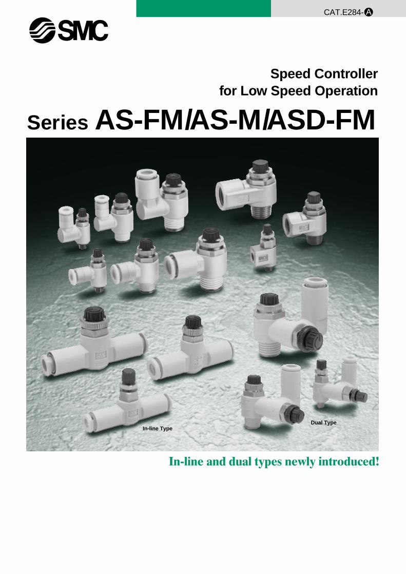
Speed Controllerfor Low Speed Operation
Series AS-FM/AS-M/ASD-FM
CAT.E284-
In-line and dual types newly introduced!
In-line TypeDual Type
A
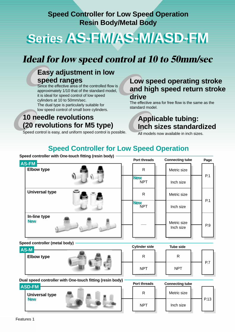
Ideal for low speed control at 10 to 50mm/sec
Speed controller with One-touch fitting (resin body)
Dual speed controller with One-touch fitting (resin body)
Port threads
R
NPT
R
NPT
Connecting tube Page
P.1
P.9
P.1
P.7
Speed Controller for Low Speed Operation
Elbow type
Universal type
AS-FM
Elbow type
R
NPT
Metric size
Inch size
P.13
AS-M
10 needle revolutions(20 revolutions for M5 type)Speed control is easy, and uniform speed control is possible.
Applicable tubing:Inch sizes standardizedAll models now available in inch sizes.
Port threads Connecting tube
Speed controller (metal body)
R
NPT
R
NPT
Metric size
Inch size
Metric size
Inch size
Metric sizeInch size
NewNew
NewNew
NewNew
NewNew
In-line type
ASD-FM
Universal type
Cylinder side Tube side
Easy adjustment in low speed rangesSince the effective area of the controlled flow isapproximately 1/10 that of the standard model,it is ideal for speed control of low speedcylinders at 10 to 50mm/sec.The dual type is particularly suitable forlow speed control of small bore cylinders.
Low speed operating stroke and high speed return stroke driveThe effective area for free flow is the same as the standard model.
Speed Controller for Low Speed OperationResin Body/Metal Body
Series AS-FM/AS-M/ASD-FMSeries AS-FM/AS-M/ASD-FM
Features 1
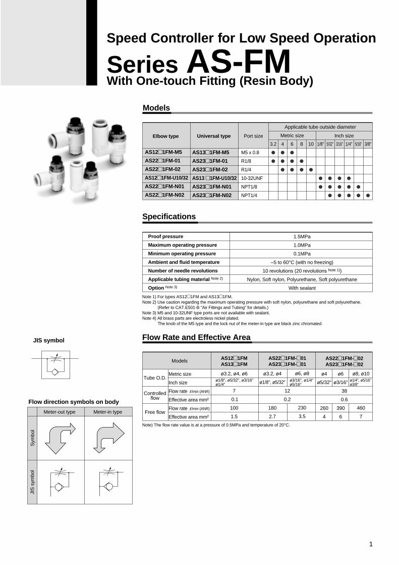
Models
Specifications
Flow Rate and Effective Area
Port size
3.2
�
�
1/8"
�
�
5/32"
�
�
�
3/16"
�
�
�
5/16"
�
�
1/4"
�
�
�
3/8"
�
Applicable tube outside diameter
10
�
8
�
�
6
�
�
�
4
�
�
�
Proof pressure
Maximum operating pressure
Minimum operating pressure
Ambient and fluid temperature
Number of needle revolutions
Applicable tubing material Note 2)
Option Note 3)
1.5MPa
1.0MPa
0.1MPa
–5 to 60°C (with no freezing)
10 revolutions (20 revolutions Note 1))
Nylon, Soft nylon, Polyurethane, Soft polyurethane
With sealant
ø1/8", ø5/32", ø3/16"ø1/4"
ø3/16", ø1/4"ø5/16"
Tube O.D.
Controlledflow
Free flow
ø3.2, ø4
ø1/8", ø5/32"
180
2.7
ø6, ø8
230
3.5
ø4
ø5/32"
260
4
ø6
ø3/16"
390
6
ø8, ø10
460
7
Note) The flow rate value is at a pressure of 0.5MPa and temperature of 20°C.
JIS symbol
Flow direction symbols on body
Meter-out type Meter-in type
Sym
bol
JIS
sym
bol
Elbow type Universal type
Models AS12�1FM AS13�1FM
ø3.2, ø4, ø6
7
0.1
100
1.5
AS22�1FM-�01AS23�1FM-�01
12
0.2
AS22�1FM-�02AS23�1FM-�02
38
0.6
AS12�1FM-M5
AS22�1FM-01
AS22�1FM-02
AS12�1FM-U10/32
AS22�1FM-N01
AS22�1FM-N02
AS13�1FM-M5
AS23�1FM-01
AS23�1FM-02
AS13 �1FM-U10/32
AS23�1FM-N01
AS23�1FM-N02
M5 x 0.8
R1/8
R1/4
10-32UNF
NPT1/8
NPT1/4
Metric size Inch size
Metric size
Inch size
Flow rate l /min (ANR)
Effective area mm²
Flow rate l /min (ANR)
Effective area mm²
ø1/4", ø5/16"ø3/8"
Note 1) For types AS12�1FM and AS13�1FM.Note 2) Use caution regarding the maximum operating pressure with soft nylon, polyurethane and soft polyurethane.
(Refer to CAT.E501-B "Air Fittings and Tubing" for details.)Note 3) M5 and 10-32UNF type ports are not available with sealant.Note 4) All brass parts are electroless nickel plated.
The knob of the M5 type and the lock nut of the meter-in type are black zinc chromated.
1
Speed Controller for Low Speed Operation
Series AS-FMWith One-touch Fitting (Resin Body)
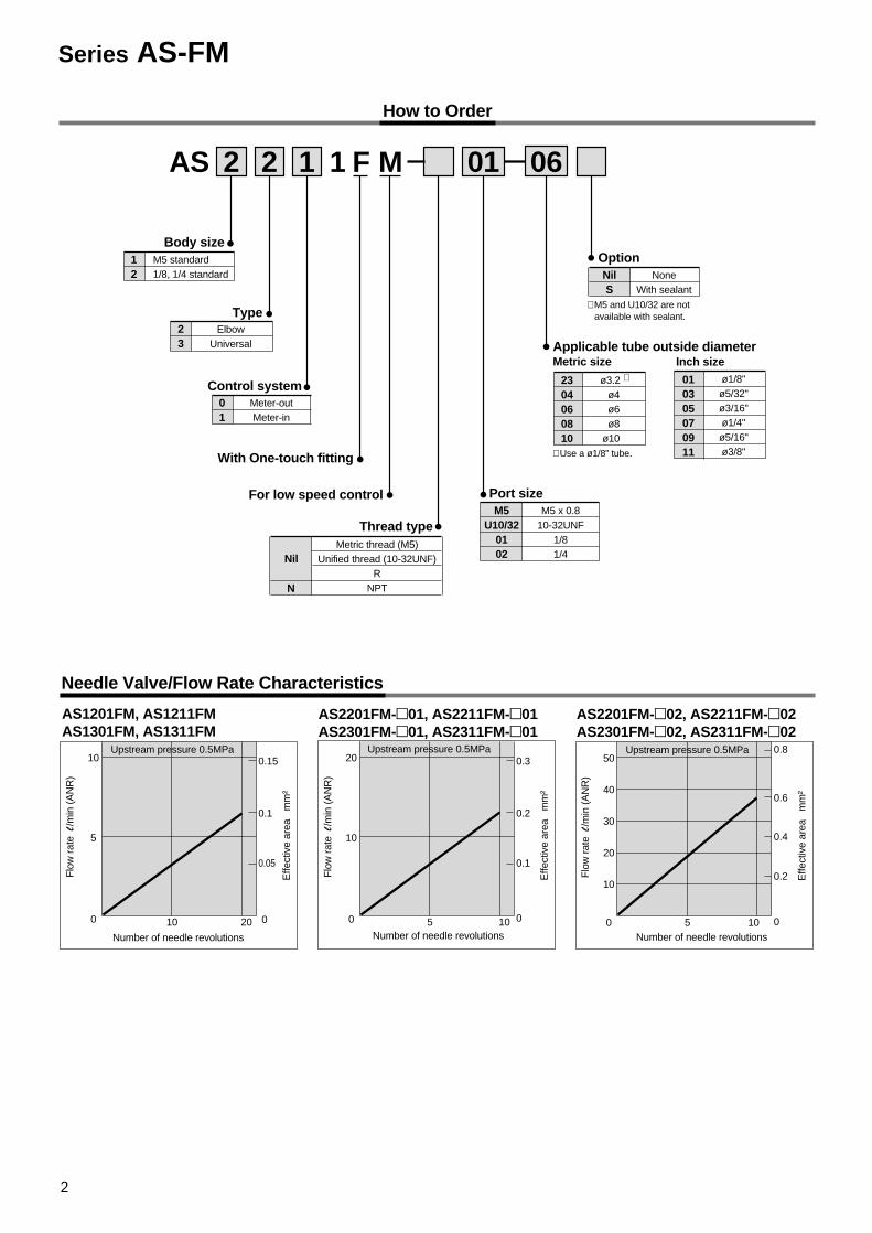
How to Order
AS
12
M5 standard1/8, 1/4 standard
Body size
Type
With One-touch fitting
Thread type
23
ElbowUniversal
NilMetric thread (M5)
Unified thread (10-32UNF)R
NPT
Port size
Option
M5U10/32
0102
M5 x 0.810-32UNF
1/81/4
NilS
NoneWith sealant
Applicable tube outside diameterMetric size Inch size
2304060810
ø3.2 ∗
ø4ø6ø8
ø10
010305070911
ø1/8"ø5/32"ø3/16"ø1/4"ø5/16"ø3/8"
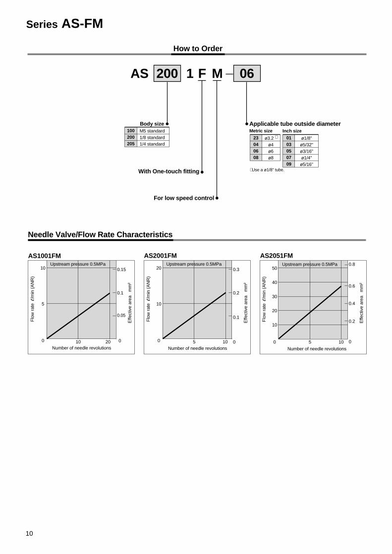
Needle Valve/Flow Rate Characteristics
01
Meter-outMeter-in
Control system
2 2 1 1 F
For low speed control
M 01 06
N
∗ Use a ø1/8" tube.
AS1201FM, AS1211FMAS1301FM, AS1311FM
AS2201FM-�01, AS2211FM-�01 AS2301FM-�01, AS2311FM-�01
AS2201FM-�02, AS2211FM-�02 AS2301FM-�02, AS2311FM-�02
Flo
w r
ate
l/m
in (
AN
R)
Effe
ctiv
e ar
ea
mm
²
0.15
0.1
0.05
Number of needle revolutions
10 20
10
5
0
Upstream pressure 0.5MPa
Flo
w r
ate
l/m
in (
AN
R)
Effe
ctiv
e ar
ea
mm
²
0.3
0.2
0.1
0
Number of needle revolutions5 10
20
10
0
Upstream pressure 0.5MPa
Flo
w r
ate
l/m
in (
AN
R)
Effe
ctiv
e ar
ea
mm
²
0.8
0.6
0.4
0.2
0
Number of needle revolutions5 10
50
40
30
20
10
0
Upstream pressure 0.5MPa
0
∗ M5 and U10/32 are not available with sealant.
Series AS-FM
2
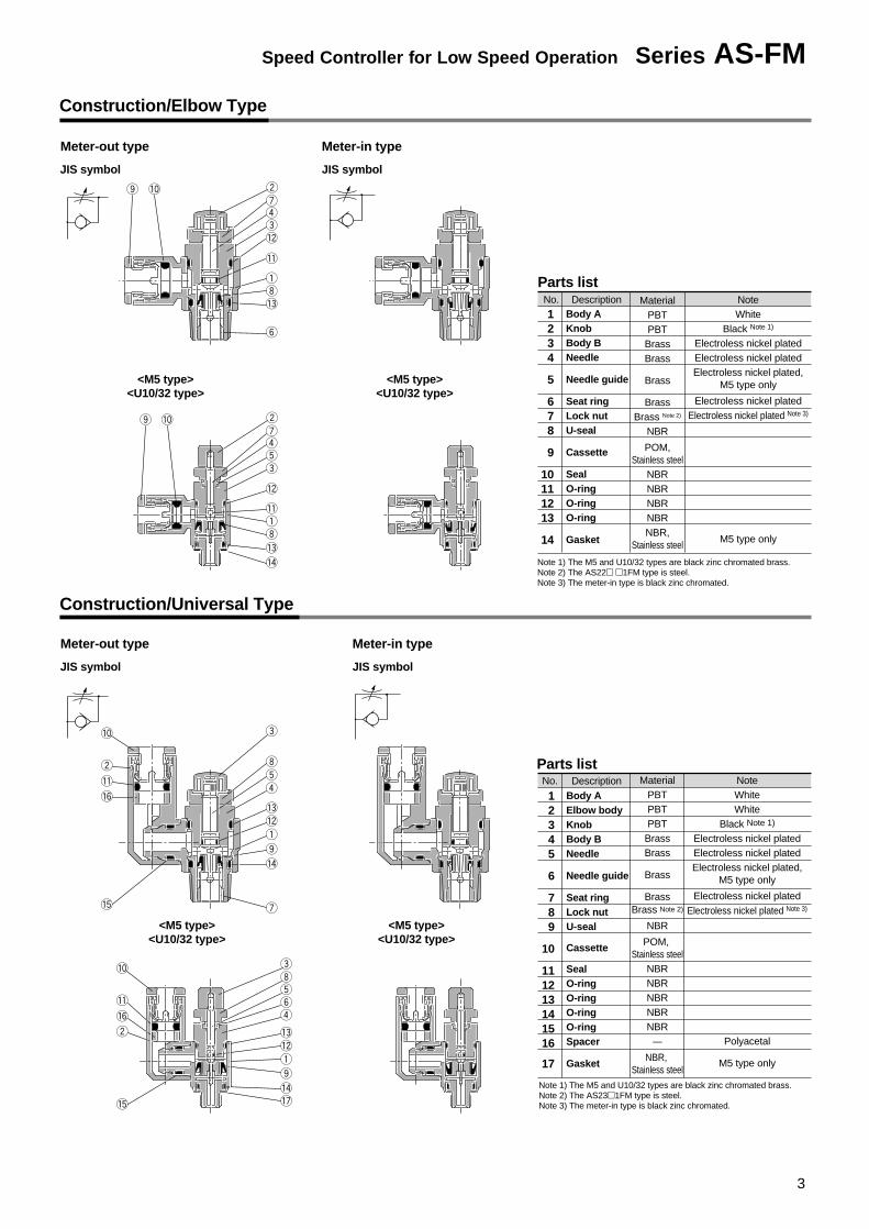
Parts list
Parts list
DescriptionNo. MaterialPBTPBT
BrassBrass
Brass
BrassBrass Note 2)
NBR
POM,Stainless steel
NBRNBRNBRNBRNBR,
Stainless steel
NoteWhite
Black Note 1)
Electroless nickel platedElectroless nickel platedElectroless nickel plated,
M5 type only
Electroless nickel platedElectroless nickel plated Note 3)
M5 type only
Note 1) The M5 and U10/32 types are black zinc chromated brass.Note 2) The AS22� �1FM type is steel.Note 3) The meter-in type is black zinc chromated.
Description MaterialPBTPBTPBT
BrassBrass
Brass
BrassBrass Note 2)
NBR
POM, Stainless steel
NBRNBRNBRNBRNBR
—
NBR, Stainless steel
No.
Construction/Elbow Type
Meter-out type
<M5 type><U10/32 type>
<M5 type><U10/32 type>
Meter-in type
Construction/Universal Type
Meter-out type Meter-in type
<M5 type><U10/32 type>
<M5 type><U10/32 type>
JIS symbol JIS symbol
JIS symbol JIS symbol
Body AElbow bodyKnobBody BNeedle
Needle guide
Seat ringLock nutU-seal
Cassette
SealO-ringO-ringO-ringO-ringSpacer
Gasket
Body AKnobBody BNeedle
Needle guide
Seat ringLock nutU-seal
Cassette
SealO-ringO-ringO-ring
Gasket
1234
5
678
9
10111213
14
12345
6
789
10
111213141516
17
NoteWhiteWhite
Black Note 1)
Electroless nickel platedElectroless nickel platedElectroless nickel plated,
M5 type only
Electroless nickel platedElectroless nickel plated Note 3)
Polyacetal
M5 type only
Note 1) The M5 and U10/32 types are black zinc chromated brass.Note 2) The AS23�1FM type is steel.Note 3) The meter-in type is black zinc chromated.
3
Speed Controller for Low Speed Operation Series AS-FM
L4
A
L3
øD2
M1
L1
L2
øD
1
T
Applicable tube O.D. ød
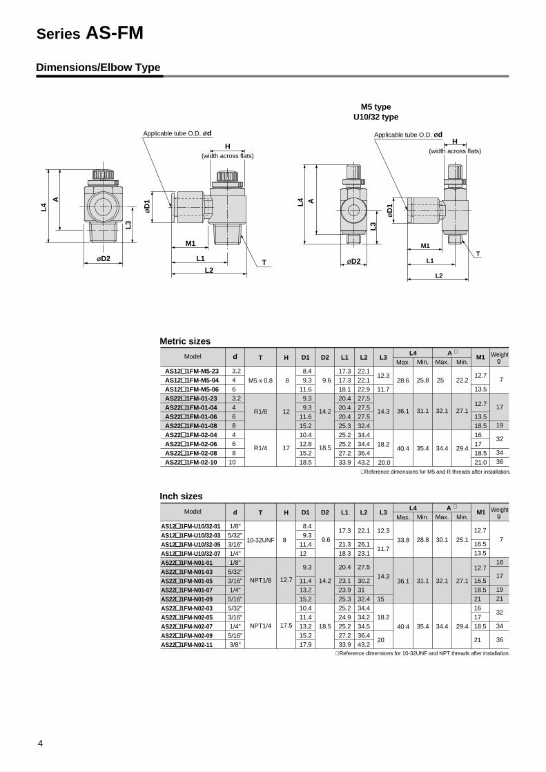
Dimensions/Elbow Type
Metric sizes
d T
M5 x 0.8
R1/8
R1/4
H
8
12
17
D1
8.4 9.311.6 9.3 9.311.615.210.412.815.218.5
D2
9.6
14.2
18.5
L1
17.317.318.120.420.420.425.325.225.227.233.9
L2
22.122.122.927.527.527.532.434.434.436.443.2
L3
12.3
11.7
14.3
18.2
20.0
Max.
28.6
36.1
40.4
Max.
25
32.1
34.4
M1
12.7
13.5
12.7
13.518.516 17 18.521.0
Weightg
7
17
19
32
3436
∗ Reference dimensions for M5 and R threads after installation.
Min.
25.8
31.1
35.4
Min.
22.2
27.1
29.4
A ∗L4
M5 typeU10/32 type
Model
AS12�1FM-M5-23 AS12�1FM-M5-04 AS12�1FM-M5-06 AS22�1FM-01-23 AS22�1FM-01-04 AS22�1FM-01-06 AS22�1FM-01-08 AS22�1FM-02-04 AS22�1FM-02-06 AS22�1FM-02-08 AS22�1FM-02-10
Inch sizes
d
1/8"5/32"3/16"1/4"1/8"5/32"3/16"1/4"5/16"5/32"3/16"1/4"5/16"3/8"
T
10-32UNF
NPT1/8
NPT1/4
H
8
12.7
17.5
D1
8.4 9.311.412
9.3
11.413.215.210.411.413.215.217.9
D2
9.6
14.2
18.5
L1
17.3
21.318.3
20.4
23.123.925.325.224.925.227.233.9
L2
22.1
26.123.1
27.5
30.231 32.434.434.234.536.443.2
L3
12.3
11.7
14.3
15
18.2
20
Max.
33.8
36.1
40.4
Max.
30.1
32.1
34.4
M1
12.7
16.513.5
12.7
16.518.521 16 17 18.5
21
Weightg
7
16
17
1921
32
34
36
∗ Reference dimensions for 10-32UNF and NPT threads after installation.
Min.
28.8
31.1
35.4
Min.
25.1
27.1
29.4
A ∗ L4Model
øD
1
Applicable tube O.D. ød
M1
L1
L2
T
H
L4
øD2
L3
A
AS12�1FM-U10/32-01AS12�1FM-U10/32-03AS12�1FM-U10/32-05AS12�1FM-U10/32-07AS22�1FM-N01-01AS22�1FM-N01-03AS22�1FM-N01-05AS22�1FM-N01-07AS22�1FM-N01-09AS22�1FM-N02-03AS22�1FM-N02-05AS22�1FM-N02-07AS22�1FM-N02-09AS22�1FM-N02-11
3.24 6 3.24 6 8 4 6 8
10
(width across flats)H
(width across flats)
Series AS-FM
4
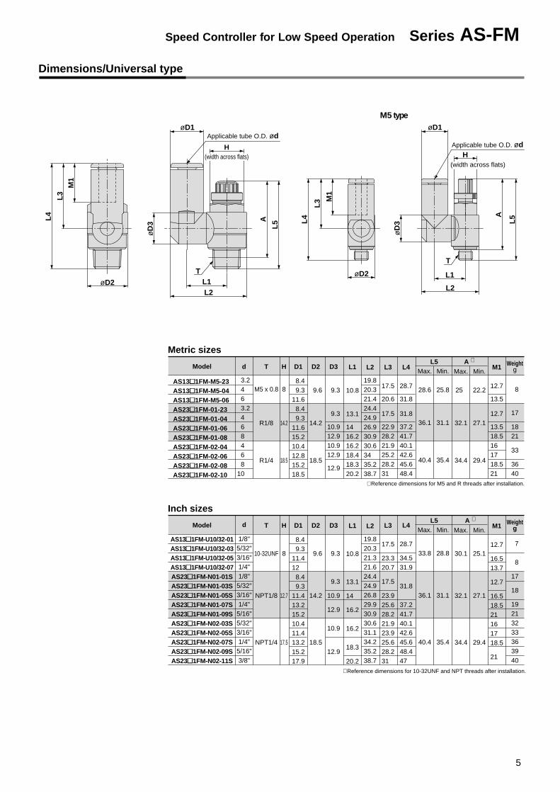
Dimensions/Universal type
Metric sizes
Model
AS13�1FM-M5-23 AS13�1FM-M5-04 AS13�1FM-M5-06 AS23�1FM-01-23 AS23�1FM-01-04 AS23�1FM-01-06 AS23�1FM-01-08 AS23�1FM-02-04 AS23�1FM-02-06 AS23�1FM-02-08 AS23�1FM-02-10
d T
M5 x 0.8
R1/8
R1/4
H
8
14.2
18.5
D1
8.4 9.311.6 8.4 9.311.615.210.412.815.218.5
D2
9.6
14.2
18.5
D3
9.3
9.3
10.912.910.912.9
12.9
L1
10.8
13.1
14 16.216.218.418.320.2
L2
19.820.321.424.424.926.930.930.634 35.238.7
L3
17.5
20.6
17.5
22.928.221.925.228.231
L4
28.7
31.8
31.8
37.241.740.142.645.648.4
Max.
28.6
36.1
40.4
Min.
25.8
31.1
35.4
L5Max.
25
32.1
34.4
Min.
22.2
27.1
29.4
A ∗ M1
12.7
13.5
12.7
13.518.516 17 18.521
Weightg
8
17
1821
33
3640
∗ Reference dimensions for M5 and R threads after installation.
M5 type
L5AL
4
M1
L3
øD2 L1L2
øD
3
øD1Applicable tube O.D. ød
T øD2
L4
M1
L3
HApplicable tube O.D. ød
øD1
L5A
T
L1
L2
øD
3
Inch sizes
Model
AS13�1FM-U10/32-01AS13�1FM-U10/32-03AS13�1FM-U10/32-05AS13�1FM-U10/32-07AS23�1FM-N01-01SAS23�1FM-N01-03SAS23�1FM-N01-05SAS23�1FM-N01-07SAS23�1FM-N01-09SAS23�1FM-N02-03SAS23�1FM-N02-05SAS23�1FM-N02-07SAS23�1FM-N02-09SAS23�1FM-N02-11S
d
1/8"5/32"3/16"1/4"1/8"5/32"3/16"1/4"5/16"5/32"3/16"1/4"5/16"3/8"
T
10-32UNF
NPT1/8
NPT1/4
H
8
12.7
17.5
D1
8.4 9.311.412 8.4 9.311.413.215.210.411.413.215.217.9
D2
9.6
14.2
18.5
D3
9.3
9.3
10.9
12.9
10.9
12.9
L1
10.8
13.1
14
16.2
16.2
18.3
20.2
L2
19.820.321.321.624.424.926.829.930.930.631.134.235.238.7
L3
17.5
23.320.7
17.5
23.925.628.221.923.925.628.231
L4
28.7
34.531.9
31.8
37.241.740.142.645.648.447
Max.
33.8
36.1
40.4
Min.
28.8
31.1
35.4
L5Max.
30.1
32.1
34.4
Min.
25.1
27.1
29.4
A ∗M1
12.7
16.513.7
12.7
16.518.521 16 17 18.5
21
Weightg
7
8
17
18
19213233363940
∗ Reference dimensions for 10-32UNF and NPT threads after installation.
3.24 6 3.24 6 8 4 6 8
10
H(width across flats)
(width across flats)
5
Speed Controller for Low Speed Operation Series AS-FM

6
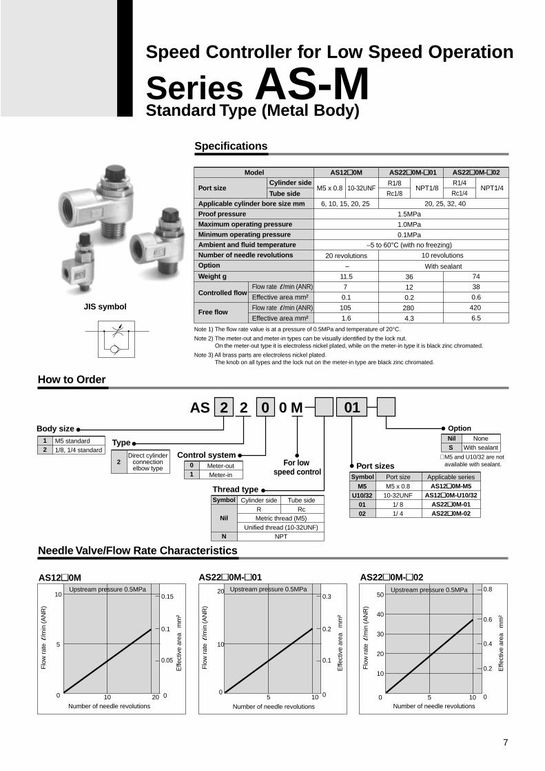
Speed Controller for Low Speed Operation
Series AS-MStandard Type (Metal Body)
AS
Specifications
Needle Valve/Flow Rate Characteristics
How to Order
12
2 Meter-outMeter-in
Body sizeM5 standard1/8, 1/4 standard
Type
Direct cylinderconnectionelbow type
Control system01
Metric thread (M5)Unified thread (10-32UNF)
NPT
Cylinder sideR
Tube sideRc
Thread typeSymbol
Nil
N
For low speed control
NoneWith sealant
NilS
Option
Applicable seriesAS12�0M-M5
AS12�0M-U10/32AS22�0M-01AS22�0M-02
Port sizeSymbol
M5U10/32
0102
Port sizes
Port size
Applicable cylinder bore size mm
Proof pressure
Maximum operating pressure
Minimum operating pressure
Ambient and fluid temperature
Number of needle revolutions
Option
Weight g
Controlled flow
Free flow
Cylinder side
Tube side
Model
Flow rate l /min (ANR)
Effective area mm²
Flow rate l /min (ANR)
Effective area mm²
JIS symbol
AS12�0M
6, 10, 15, 20, 25
20 revolutions
–
11.5
7
0.1
105
1.6
AS22�0M-�01
20, 25, 32, 40
1.5MPa
1.0MPa
0.1MPa
–5 to 60°C (with no freezing)
10 revolutions
With sealant
36
12
0.2
280
4.3
AS22�0M-�02
74
38
0.6
420
6.5
M5 x 0.8 10-32UNF NPT1/8 NPT1/4R1/8
Rc1/8
R1/4
Rc1/4
2 2 0 0 M
M5 x 0.810-32UNF
1/ 81/ 4
AS12�0M AS22�0M-�01 AS22�0M-�02
Flo
w r
ate
l/m
in (
AN
R)
Effe
ctiv
e ar
ea
mm
²
0.15
0.1
0.05
Number of needle revolutions10 20
10
5
0
Upstream pressure 0.5MPa
Flo
w r
ate
l/m
in (
AN
R)
Effe
ctiv
e ar
ea
mm
²
0.3
0.2
0.1
0
Number of needle revolutions
5 10
20
10
0
Upstream pressure 0.5MPa
Flo
w r
ate
l/m
in (
AN
R)
Effe
ctiv
e ar
ea
mm
²
0.8
0.6
0.4
0.2
0Number of needle revolutions
5 10
50
40
30
20
10
0
Upstream pressure 0.5MPa
0
Note 1) The flow rate value is at a pressure of 0.5MPa and temperature of 20°C.
Note 2) The meter-out and meter-in types can be visually identified by the lock nut. On the meter-out type it is electroless nickel plated, while on the meter-in type it is black zinc chromated.
Note 3) All brass parts are electroless nickel plated. The knob on all types and the lock nut on the meter-in type are black zinc chromated.
∗ M5 and U10/32 are not available with sealant.
01
7
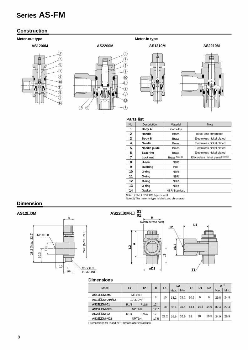
Construction
Dimension
Meter-out type Meter-in type
Parts listNo.
1234567891011121314
Description Material
Zinc alloy
Brass
Brass
Brass
Brass
Brass
Brass Note 1)
NBR
PBT
NBR
NBR
NBR
NBR
NBR/Stainless
Note
Black zinc chromated
Electroless nickel plated
Electroless nickel plated
Electroless nickel plated
Electroless nickel plated
Electroless nickel plated Note 2)
Note 1) The AS22�0M type is steel.Note 2) The meter-in type is black zinc chromated.
AS1200M AS2200M AS1210M AS2210M
Body A
Handle
Body B
Needle
Needle guide
Seat ring
Lock nut
U-seal
Bushing
O-ring
O-ring
O-ring
O-ring
Gasket
24.8
(M
ax. 2
9.8)
8
28.2
(M
ax. 3
3.2)
ø9
10.3
10
M5 x 0.8
M5 x 0.810-32UNF
AS12�0M
Dimensions
T1 T2 H L1
10
18
27.2
Max.
33.2
36.4
39.9
Min.
28.2
31.4
35.9
L2L3
10.3
14.1
18
D2
9
14.6
19.5
D1
9
14.3
18
Max.
29.8
32.4
34.9
∗ Dimensions for R and NPT threads after installation
Min.
24.8
27.4
29.9
A ∗
AS22�0M-� 0102
L2 A
L3
øD2
L1
øD
1
T1
T2
Model
AS12�0M-M5
AS12�0M-U10/32
AS22�0M-01
AS22�0M-N01
AS22�0M-02
AS22�0M-N02
M5 x 0.8
10-32UNF
NPT1/8
NPT1/4
R1/8
R1/4
Rc1/8
Rc1/4
�9
8
12
12.7
17
17.5
H(width across flats)
Series AS-FM
8

Speed Controller for Low Speed Operation
Series AS-FMIn-line Type
Specifications
Flow Rate and Effective Area
Applicable cylinder bore size
(mm)3.2
�
1/8"
�
5/32"
�
�
3/16"
�
�
�
1/4"
�
�
�
5/16"
�
Applicable tubing O.D.
8
�
6
�
�
�
4
�
�
Proof pressure
Maximum operating pressure
Minimum operating pressure
Ambient and fluid temperature
Number of needle revolutions
Applicable tubing materials Note 2)
1.5MPa
1MPa
0.1MPa
0 to 60°C
10 revolutions (20 revolutions Note 1) )
Nylon, Soft nylon, Polyurethane, Soft polyurethane
Flow rate l/min (ANR)
Effective area mm²
Flow rate l/min (ANR)
Effective area mm²
ø1/8", ø5/32", ø3/16"ø1/4"
Tube O.D.
Controlledflow
Free flow
ø4
ø5/32"
130
2
ø6
ø3/16", ø1/4"
230
3.5
ø6
ø3/16"
290
4.5
ø8
ø1/4", ø5/16"
460
7
Note) The flow rate value is at a pressure of 0.5MPa and temperature of 20°C.
Model
Model AS1001FM
ø3.2, ø4, ø6
7
0.1
100
1.5
AS2001FM
12
0.2
AS2051FM
38
0.6
AS1001FM
AS2001FM
AS2051FM
6, 10, 16, 20
20, 25, 32
20, 25, 32, 40
Metric size Inch size
Metric size
Inch size
Models
Flow direction symbols on body
Sym
bol
JIS
sym
bol
Note 1) For type AS1001FM.Note 2) Use caution regarding the maximum operating pressure with soft nylon, polyurethane and soft polyurethane.
(Refer to CAT.E501-B "Air Fittings and Tubing" for details.)Note 3) All brass parts are electroless nickel plated.
The knob of the M5 type is black zinc chromated.
9
AS
Needle Valve/Flow Rate Characteristics
How to Order
100200205
Body sizeM5 standard1/8 standard1/4 standard
23040608
Applicable tube outside diameterMetric size
ø3.2 ∗
ø4ø6ø8
0103050709
ø1/8"ø5/32"ø3/16"ø1/4"ø5/16"
For low speed control
With One-touch fitting
200 1 F M 06
Inch size
∗ Use a ø1/8" tube.
AS1001FM AS2001FM AS2051FM
Flo
w r
ate
l/m
in (
AN
R)
Effe
ctiv
e ar
ea
mm
²
0.15
0.1
0.05
Number of needle revolutions10 20
10
5
0
Upstream pressure 0.5MPa
Flo
w r
ate
l/m
in (
AN
R)
Effe
ctiv
e ar
ea
mm
²
0.3
0.2
0.1
0Number of needle revolutions
5 10
20
10
0
Upstream pressure 0.5MPa F
low
rat
e l
/min
(A
NR
)
Effe
ctiv
e ar
ea
mm
²
0.8
0.6
0.4
0.2
0
Number of needle revolutions
5 10
50
40
30
20
10
0
Upstream pressure 0.5MPa
0
Series AS-FM
10
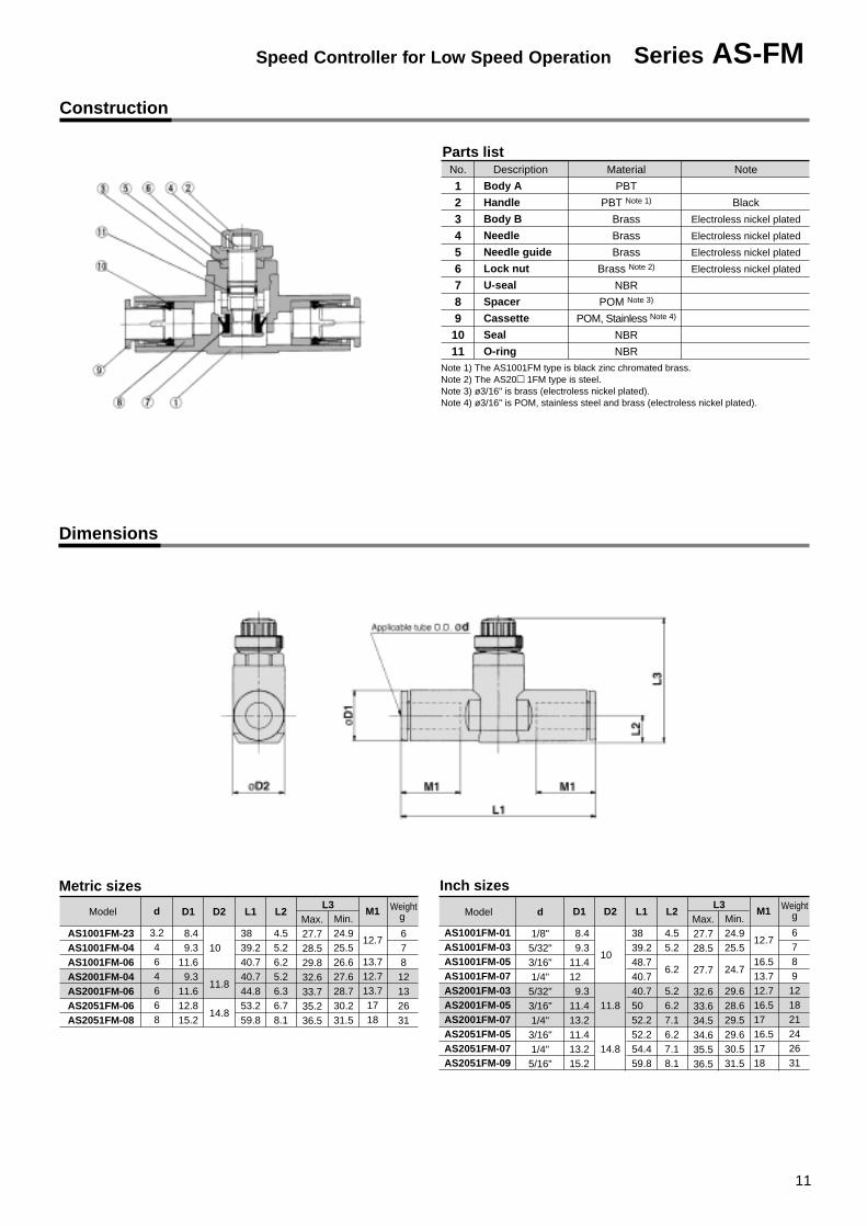
Metric sizes
d
3.2464668
D1
8.4 9.311.6 9.311.612.815.2
D2
10
11.8
14.8
L1
38 39.240.740.744.853.259.8
L2
4.55.26.25.26.36.78.1
Max.27.728.529.832.633.735.236.5
M1
12.7
13.712.713.71718
Weightg
678
12132631
Min.24.925.526.627.628.730.231.5
L3Model
Inch sizes
d
1/8"5/32"3/16"1/4"
5/32"3/16"1/4"
3/16"1/4"
5/16"
D1
8.4 9.311.412 9.311.413.211.413.215.2
D2
10
11.8
14.8
L1
38 39.248.740.740.750 52.252.254.459.8
L2
4.55.2
6.2
5.26.27.16.27.18.1
Max.27.728.5
27.7
32.633.634.534.635.536.5
M1
12.7
16.513.712.716.517 16.517 18
Weightg
6789121821242631
Min.24.925.5
24.7
29.628.629.529.630.531.5
L3Model
AS1001FM-01AS1001FM-03AS1001FM-05AS1001FM-07AS2001FM-03AS2001FM-05AS2001FM-07AS2051FM-05AS2051FM-07AS2051FM-09
Construction
Dimensions
Parts listNo.
1234567891011
Description Material
PBT
PBT Note 1)
Brass
Brass
Brass
Brass Note 2)
NBR
POM Note 3)
POM, Stainless Note 4)
NBR
NBR
Note
Black
Electroless nickel plated
Electroless nickel plated
Electroless nickel plated
Electroless nickel plated
Note 1) The AS1001FM type is black zinc chromated brass.Note 2) The AS20� 1FM type is steel.Note 3) ø3/16" is brass (electroless nickel plated).Note 4) ø3/16" is POM, stainless steel and brass (electroless nickel plated).
Body A
Handle
Body B
Needle
Needle guide
Lock nut
U-seal
Spacer
Cassette
Seal
O-ring
AS1001FM-23AS1001FM-04AS1001FM-06AS2001FM-04AS2001FM-06AS2051FM-06AS2051FM-08
11
Speed Controller for Low Speed Operation Series AS-FM

12
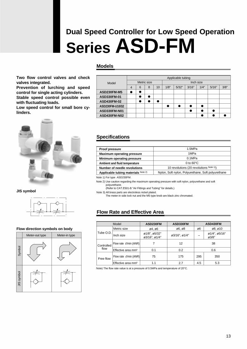
Models
Specifications
Flow Rate and Effective Area
ASD230FM-M5ASD330FM-01ASD430FM-02ASD230FM-U10/32ASD330FM-N01ASD430FM-N02
Model
Applicable tubingMetric size Inch size
4
�6
���
8
��
10
�
1/8"
�
5/32"
�
3/16"
��
1/4"
���
5/16"
��
3/8"
�
Proof pressure
Maximum operating pressure
Minimum operating pressure
Ambient and fluid temperature
Number of needle revolutions
Applicable tubing materials Note 2)
1.5MPa
1MPa
0.1MPa
0 to 60°C10 revolutions (20 revolutions Note 1))
Nylon, Soft nylon, Polyurethane, Soft polyurethane
Note) The flow rate value is at a pressure of 0.5MPa and temperature of 20°C.
Model
Tube O.D.
Controlledflow
Free flow
Metric size
Inch size
Flow rate l /min (ANR)
Effective area mm²
Flow rate l /min (ANR)
Effective area mm²
ASD230FM ASD330FM ASD430FM
ø4, ø6
7
0.1
1.1
75
ø6, ø8
12 38
0.60.2
175 350
5.32.7
ø8, ø10ø6
295
4.5
ø1/8", ø5/32"ø3/16", ø1/4"
ø1/4", ø5/16"ø3/8"
ø3/16", ø1/4" –
JIS symbol
Flow direction symbols on body
Meter-out type Meter-in type
Sym
bol
JIS
sym
bol
Two flow control valves and check valves integrated.Prevention of lurching and speed control for single acting cylinders.Stable speed control possible even with fluctuating loads.Low speed control for small bore cy-linders.
Note 1) For type ASD230FM.
Note 2) Use caution regarding the maximum operating pressure with soft nylon, polyurethane and soft polyurethane.(Refer to CAT.E501-B "Air Fittings and Tubing" for details.)
Note 3) All brass parts are electroless nickel plated.The meter-in side lock nut and the M5 type knob are black zinc chromated.
Dual Speed Controller for Low Speed Operation
Series ASD-FM
13
Series ASD-FM
14
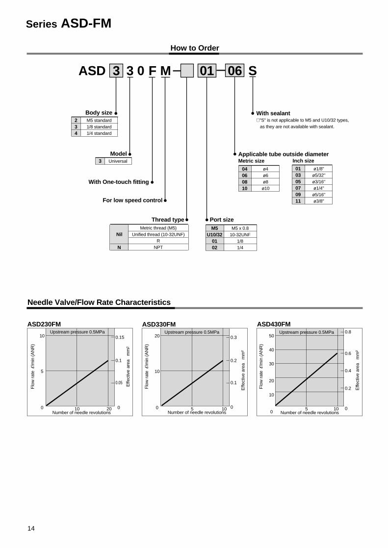
How to Order
ASD
234
M5 standard1/8 standard1/4 standard
Body size
Model
With One-touch fitting
Thread type
3 Universal
NilMetric thread (M5)
Unified thread (10-32UNF)R
NPT
Port size
With sealant∗ "S" is not applicable to M5 and U10/32 types, as they are not available with sealant.
M5U10/32
0102
M5 x 0.810-32UNF
1/81/4
Applicable tube outside diameterMetric size Inch size
04060810
ø4ø6ø8ø10
010305070911
ø1/8"ø5/32"ø3/16"ø1/4"ø5/16"ø3/8"
Needle Valve/Flow Rate Characteristics
33 0 F
For low speed control
M 01 06 S
N
ASD230FM ASD330FM ASD430FM
Flo
w r
ate
l/m
in (
AN
R)
Effe
ctiv
e ar
ea
mm
2
0.15
0.1
0.05
Number of needle revolutions10 20
10
5
0
Upstream pressure 0.5MPa
Flo
w r
ate
l/m
in (
AN
R)
Effe
ctiv
e ar
ea
mm
²
0.3
0.2
0.1
0Number of needle revolutions
5 10
20
10
0
Upstream pressure 0.5MPa
Flo
w r
ate
l/m
in (
AN
R)
Effe
ctiv
e ar
ea
mm
²
0.8
0.6
0.4
0.2
0Number of needle revolutions
5 10
50
40
30
20
10
0
Upstream pressure 0.5MPa
0
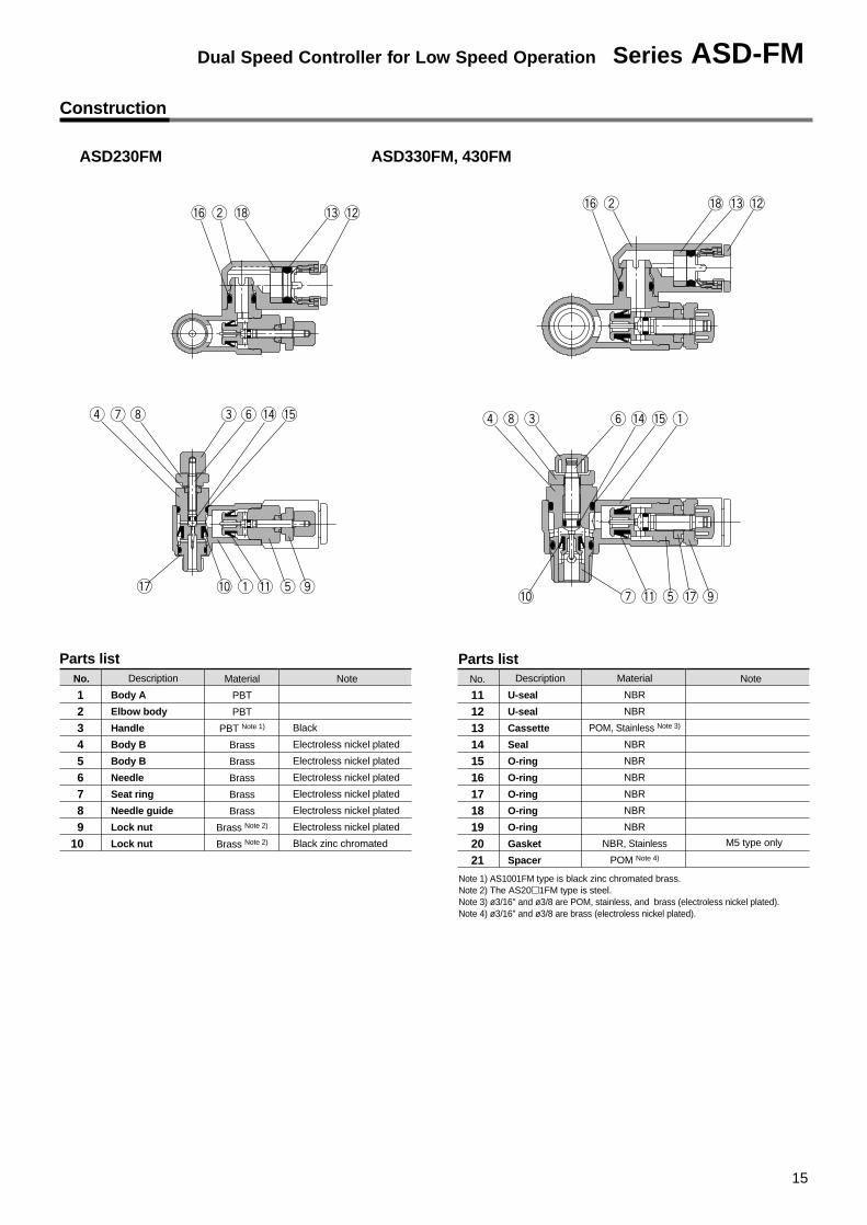
15
Construction
Parts listNo.
Body A
Elbow body
Handle
Body B
Body B
Needle
Seat ring
Needle guide
Lock nut
Lock nut
Material
PBT
PBT
PBT Note 1)
Brass
Brass
Brass
Brass
Brass
Brass Note 2)
Brass Note 2)
Note
Black
Electroless nickel plated
Electroless nickel plated
Electroless nickel plated
Electroless nickel plated
Electroless nickel plated
Electroless nickel plated
Black zinc chromated
Description No.
1112131415161718192021
Material
NBR
NBR
POM, Stainless Note 3)
NBR
NBR
NBR
NBR
NBR
NBR
NBR, Stainless
POM Note 4)
NoteDescription
U-seal
U-seal
Cassette
Seal
O-ring
O-ring
O-ring
O-ring
O-ring
Gasket
Spacer
M5 type only
ASD230FM ASD330FM, 430FM
Parts list
123456789
10
Note 1) AS1001FM type is black zinc chromated brass.Note 2) The AS20�1FM type is steel.Note 3) ø3/16" and ø3/8 are POM, stainless, and brass (electroless nickel plated).Note 4) ø3/16" and ø3/8 are brass (electroless nickel plated).
Dual Speed Controller for Low Speed Operation Series ASD-FM
16
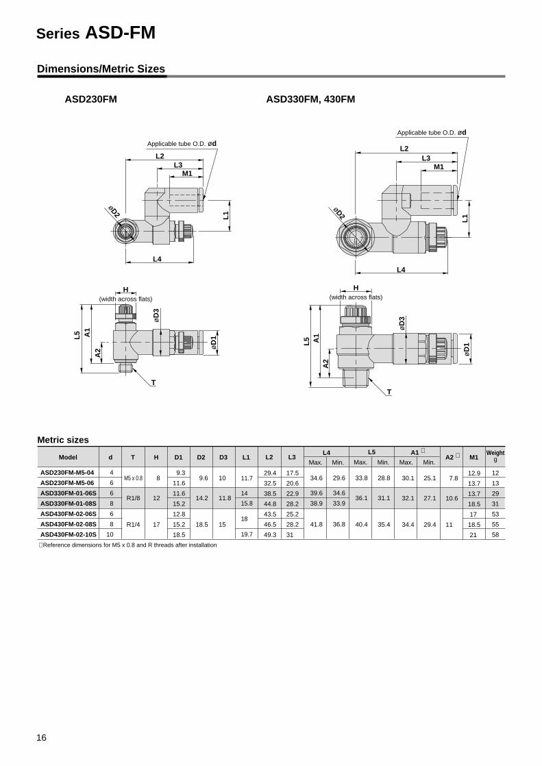
Dimensions/Metric Sizes
7.8
10.6
11
d T H D1 D2 D3 L1 L2 L3Model
ASD230FM-M5-04
ASD230FM-M5-06
ASD330FM-01-06S
ASD330FM-01-08S
ASD430FM-02-06S
ASD430FM-02-08S
ASD430FM-02-10S
M5 x 0.8
R1/8
R1/4
8
12
17
4
6
6
8
6
8
10
9.3
11.6
11.6
15.2
12.8
15.2
18.5
9.6
14.2
18.5
10
11.8
15
11.7
14
15.8
18
19.7
29.4
32.5
38.5
44.8
43.5
46.5
49.3
17.5
20.6
22.9
28.2
25.2
28.2
31
34.6
39.6
38.9
41.8
29.6
34.6
33.9
36.8
33.8
36.1
40.4
28.8
31.1
35.4
30.1
32.1
34.4
25.1
27.1
29.4
12.9
13.7
13.7
18.5
17
18.5
21
L4 L5 A1 ∗A2 ∗ M1
Max. Min. Max. Max.Min. Min.
Weightg
Applicable tube O.D. ød
L2L3
M1
L4
L1
L5 A1
A2
øD
3
øD
1
T
øD2
ASD230FM
Metric sizes
12
13
29
31
53
55
58
Applicable tube O.D. ød
L2L3
M1
L1
L4
T
L5 A1
A2
øD
3
øD
1
øD2
ASD330FM, 430FM
∗ Reference dimensions for M5 x 0.8 and R threads after installation
H(width across flats)
H(width across flats)
Series ASD-FM
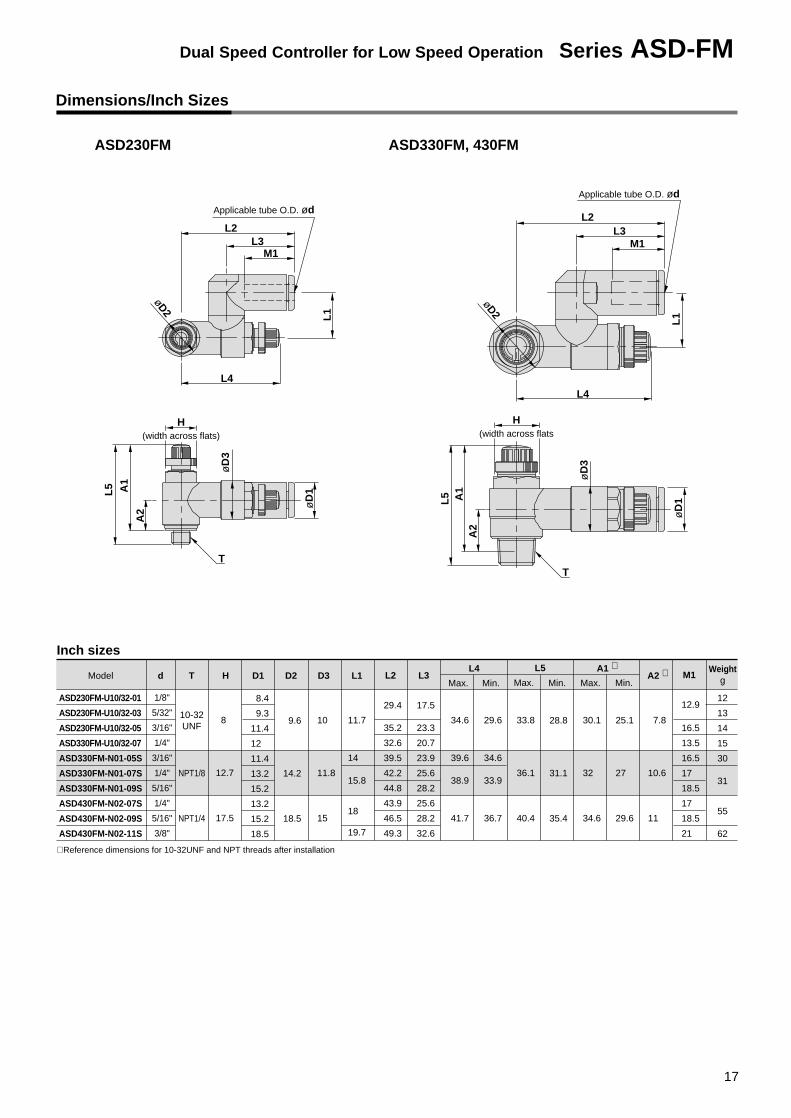
10-32UNF
NPT1/8
NPT1/4
7.8
10.6
11
d T H D1 D2 D3 L1 L2 L3Model
ASD230FM-U10/32-01
ASD230FM-U10/32-03
ASD230FM-U10/32-05
ASD330FM-U10/32-07
ASD330FM-N01-05S
ASD330FM-N01-07S
ASD330FM-N01-09S
ASD430FM-N02-07S
ASD430FM-N02-09S
ASD430FM-N02-11S
8
12.7
17.5
1/8"
5/32"
3/16"
1/4"
3/16"
1/4"
5/16"
1/4"
5/16"
3/8"
8.4
9.3
11.4
12
11.4
13.2
15.2
13.2
15.2
18.5
9.6
14.2
18.5
10
11.8
15
11.7
14
15.8
18
19.7
29.4
35.2
32.6
39.5
42.2
44.8
43.9
46.5
49.3
17.5
23.3
20.7
23.9
25.6
28.2
25.6
28.2
32.6
34.6
39.6
38.9
41.7
29.6
34.6
33.9
36.7
33.8
36.1
40.4
28.8
31.1
35.4
30.1
32
34.6
25.1
27
29.6
12.9
16.5
13.5
16.5
17
18.5
17
18.5
21
L4 L5 A1 ∗A2 ∗ M1
Max. Min. Max. Max.Min. Min.
Weightg
∗ Reference dimensions for 10-32UNF and NPT threads after installation
Inch sizes
Applicable tube O.D. ød
L2L3
M1
L4
L1
L5 A1
A2
øD
3
øD
1
T
øD2
ASD230FM
Applicable tube O.D. ød
L2L3
M1
L1
L4
T
L5 A1
A2
øD
3
øD
1
øD2
ASD330FM, 430FM
12
13
14
15
30
31
55
62
Dimensions/Inch Sizes
H(width across flats)
H(width across flats
Dual Speed Controller for Low Speed Operation Series ASD-FM
17
Safety Instructions
These safety instructions are intended to prevent a hazardous situation and/or equipment damage. These instructions indicate the level of potential hazard by labels of "Caution", "Warning" or "Danger". To ensure safety, be sure to observe ISO 4414 Note 1), JIS B 8370 Note 2) and other safety practices.
1. The compatibility of pneumatic equipment is the responsibility of the person who designs the pneumatic system or decides its specifications.Since the products specified here are used in various operating conditions, their compatibility for the specific pneumatic system must be based on specifications or after analysis and/or tests to meet your specific requirements.
2. Only trained personnel should operate pneumatically operated machinery and equipment.Compressed air can be dangerous if an operator is unfamiliar with it. Assembly, handling or repair of pneumatic systems should be performed by trained and experienced operators.
3. Do not service machinery/equipment or attempt to remove components until safety is confirmed.
1. Inspection and maintenance of machinery/equipment should only be performed after confirmation of safe locked-out control positions.
2. When equipment is to be removed, confirm the safety process as mentioned above. Cut the supply pressure for this equipment and exhaust all residual compressed air in the system.
3. Before machinery/equipment is restarted, take measures to prevent shooting-out of cylinder piston rod, etc. (Bleed air into the system gradually to create back pressure.)
4. Contact SMC if the product is to be used in any of the following conditions:1. Conditions and environments beyond the given specifications, or if product is used outdoors.2. Installation on equipment in conjunction with atomic energy, railway, air navigation, vehicles, medical
equipment, food and beverage, recreation equipment, emergency stop circuits, press applications, or safety equipment.
3. An application which has the possibility of having negative effects on people, property, or animals, requiring special safety analysis.
Note 1) ISO 4414 : Pneumatic fluid power -- Recommendations for the application of equipment to transmission and control systems
Note 2) JIS B 8370 : General Rules for Pneumatic Systems
Warning
Caution : Operator error could result in injury or equipment damage.
Warning : Operator error could result in serious injury or loss of life.
Danger : In extreme conditions, there is a possible result of serious injury or loss of life.
Series AS-FM/AS-M/ASD-FM
18
WarningSelection
Caution
Mounting
Piping
Air Supply
1. Confirm the specifications.The products appearing in this catalog are designed for use only in compressed air systems (including vacuum).Do not use outside the specified ranges of pressure, tempera-ture, etc., as this may cause damage or malfunction. (Refer to specifications.)Consult with SMC if fluids other than compressed air (including vacuum) are to be used.
1. Read the instruction manual carefully.The product should be mounted and operated with a good un-derstanding of its contents. Also, keep the manual where it can be easily referred to at any time.
2. Ensure space for maintenance.Ensure the necessary space for maintenance activities.
3. Be sure to tighten screws with the proper torque.When mounting, tighten screws with the recommended torque.
1. Preparation before pipingBefore piping is connected, it should be thoroughly blown out with air (flushing) or washed to remove chips, cutting oil and other debris from inside the pipe.
2. Wrapping of pipe tapeWhen screwing together pipes, fittings, etc., be certain that chips from the pipe threads and sealing material do not get in-side the piping.
Further, when pipe tape is used, leave 1.5 to 2 thread ridges exposed at the end of the threads.
1. Types of fluidThis product is designed for use with compressed air. Contact SMC if a different fluid is to be used.Contact SMC regarding products to be used with general pur-pose fluids, to confirm which fluids may be used.
2. When there is a large amount of drainageCompressed air containing a large amount of drainage may cause the malfunction of pneumatic equipment. An air dryer or Drain Catch should be installed upstream from filters.
3. Drain managementIf the air filter drains are not flushed regularly, the drainage will flow downstream and may lead to the malfunction of pneumatic equipment.In cases where the management of drain flushing will be diffi-cult, the use of filters with automatic drains is recommended.For details on the quality of compressed air mentioned above, refer to SMC's "Air Cleaning Equipment " catalog.
4. Types of airDo not use compressed air containing chemicals, synthetic oil which includes organic solvents, salt, corrosive gases, etc., as this may cause damage or malfunction.
5. In cases where a large amount of carbon dust is generated by the compressor, it will adhere to valves and may cause malfunction. In this situation, the use of a mist separator is rec-ommended.
Warning
Warning
Warning
Operating Environment
1. Do not operate in an atmosphere of corrosive gases, chemicals, sea water, fresh water or water vapor, or where there is contact with same.
2. In locations which receive direct sunlight, the sunlight should be blocked .
3. Do not operate in situations where vibration or shock will occur.
4. Do not operate in locations near heat sources where radiated heat will be received.
Maintenance
Warning1. Perform maintenance in accordance with
procedures in the instruction manual.Improper handling may cause damage or malfunction of equip-ment or machinery.
2. Maintenance workImproper handling of compressed air is dangerous. Therefore, in addition to observing the product specifications, replacement of elements and other maintenance activities should be per-formed by personnel having sufficient knowledge and experi-ence pertaining to pneumatic equipment.
3. Drain flushingDrainage should be flushed from air filter and other drains on a regular basis.
4. Pre-maintenance inspectionWhen removing this product, turn off the electric power, and be certain to shut off the supply pressure and exhaust the com-pressed air in the system. Proceed only after confirming that all pressure has been released to the atmosphere.
5. Post maintenance inspectionAfter installation, repair or reconstruction, reconnect pressur-ized air and electric power, and then perform inspections for proper operation and air leakage. If the sound of air leakage can be heard, or if the equipment does not operate properly, stop operation and confirm that it is mounted correctly.
6. Disassembly and alteration prohibited.Do not disassemble the unit or make any alterations to it.
Series AS-FM/AS-M/ASD-FMFlow Control Equipment PrecautionsBe sure to read before handling.
19
Series ASD-FM Specific Product Precautions
1. This product cannot be used as a stop valve requiring zero air leakage.A certain amount of air leakage is allowed for in the product's specifications.
2. Confirm whether PTFE can be used.PTFE (tetrafluoroethylene resin) powder is contained in the sealing agent. Confirm that there will be no operational problem.
Selection
1. Confirm that the lock nut is not loose.If the lock nut is loose, there may be dangerous changes in actua-tor speed .
2. The number of opening and closing revolu-tions of the needle valve should be adjusted within the range of the specifications.Since it has a pull-out stop mechanism, it will not revolve past the limit. Confirm the number of revolutions for the product to be used, as excessive turning of the needle will cause damage.
3. Mount after confirming the direction of flow.Mounting backwards is dangerous, because the speed adjust-ment needle will not work and the actuator may lurch suddenly.
4. To adjust the speed, start with the needle in the completely closed position and then ad-just by opening gradually.When the needle valve is opening, the actuator may lurch sud-denly creating a dangerous situation.Moreover, the needle valve is closed by turning to the right and opened by turning to the left. Therefore, the actuator speed is reduced by turning to the right and increased by turning to the left.
5. Install and remove by tightening or loosening the hexagon wrench flats on Body B with a suitable wrench.Damage may occur if any other part is used. Adjustment of the position after mounting should be performed by turning Body A by hand.
6. Do not use a universal type fitting where rota-tion normally occurs.The fitting section may be damaged.
Mounting and Adjustment
1. Controlling a single acting cylinderWhen controlling a single acting cylinder, the cylinder's return speed will differ depending on the operating conditions. Operate after confirming the maximum return speeds shown in the table below.
Caution
<Operating conditions>• Cylinder extension speed: 100mm/s• Meter-out needle fully open
(Reference) Recommended circuit for high return speedWhen low extension speed and high return speed are desired, the following circuit using 3 ports is recommended.
Note) Use Series AS-F with -X214 for the throttle valve.
Speedcontroller Cylinder Solenoid
valve Tube SilencerMaximum return speed mm/s
100 200 300
ASD230FM CJ2 VJ500 TU06041m
AN110-01
ASD330FM CM2 VZ500 TU06041m
AN110-01
100mm/s
Operation
Return speed
Cylinder size
ø16
ø10
ø6
ø20
ø25
ø32
Cylinder size
Warning
Warning
Handling of One-touch Fittings
Caution1. Refer to CAT.E504-B "Air Fittings and Tubing" page
159 for handling of One-touch fittings.
∗ Values for pressure of 0.5MPa and temperature of 20°C.
1. The proper tightening torque for pipe fittings is as shown in the table. As a rule, they should be tightened 2 to 3 turns with a tool after first tightening by hand.Be careful not to cause damage by over-tightening.
Tightening Torque
Caution
M510/32-UNF
1/6 turn afterhand tightening 8 100
1/81/4
7 to 912 to 14
12 (12.7)17 (17.5)
150200
1N⋅m=10.2kgf⋅cm
Male thread Proper fastening torque N⋅m Width across flats mm Nominal size of adjustableangle wrench mm
Note) Values inside ( ) are NPT thread dimensions.
Note)
Series AS-FM/AS-M/ASD-FMSpecific Product PrecautionsBe sure to read before handling.Refer to pages 18 and 19 for safety precautions and flow control equipment precautions.
20


EUROPESWEDENSMC Pneumatics Sweden AB
SWITZERLANDSMC Pneumatik AG.
UKSMC Pneumatics (U.K.) Ltd.
ASIACHINASMC (China) Co., Ltd.
HONG KONGSMC Pneumatics (Hong kong) Ltd.
INDIASMC Pneumatics (India) Pvt. Ltd.
MALAYSIASMC Pneumatics (S.E.A.) Sdn. Bhd.
PHILIPPINESSMC Pneumatics (Philippines), Inc.
SINGAPORESMC Pneumatics (S.E.A.) Pte. Ltd.SOUTH KOREASMC Pneumatics Korea Co., Ltd.
TAIWANSMC Pneumatics (Taiwan) Co., Ltd.
THAILANDSMC Thailand Ltd.
NORTH AMERICACANADASMC Pneumatics (Canada) Ltd.
MEXICOSMC Corporation (Mexico) S.A. de C.V.USASMC Pneumatics, Inc.
SOUTH AMERICAARGENTINASMC Argentina S.A.
BOLIVIASMC Pneumatics Bolivia S.R.L.
BRAZILSMC Pneumaticos Do Brazil Ltda.
CHILESMC Pneumatics (Chile) S.A.
VENEZUELASMC Neumatica Venezuela S.A.
OCEANIAAUSTRALIASMC Pneumatics (Australia) Pty. Ltd.
NEW ZEALANDSMC Pneumatics (N.Z.) Ltd.
EUROPEAUSTRIASMC Pneumatik GmbH
CZECH
SMC Czech s.r.o.
DENMARKSMC Pneumatik A/S
FINLANDSMC Pneumatiikka OY
FRANCESMC Pneumatique SA
GERMANYSMC Pneumatik GmbH
HUNGARYSMC Hungary Kft.
IRELANDSMC Pneumatics (Ireland) Ltd.
ITALY/ROMANIASMC Italia S.p.A.
NETHERLANDSSMC Pnuematics BV.
NORWAYSMC Pneumatics Norway A/S
RUSSIA SMC Pneumatik LLC.
SLOVAKIASMC Slovakia s.r.o.
SLOVENIASMC Slovenia d.o.c.
SPAIN/PORTUGALSMC España, S.A.
SMC'S GLOBAL MANUFACTURING, DISTRIBUTION AND SERVICE NETWORK
1-16-4 Shimbashi, Minato-ku, Tokyo 105-0004 JAPANTel: 03-3502-2740 Fax: 03-3508-2480
Specifications are subject to change without prior notice and any obligation on the part of the manufacturer.
Printed in Japan.1st printing March, 1999 D-SMC.L.A. P-77.5 (YG)