Speed and position control of autonomous mobile robot on variable
9
GUNES & BABA: MOBILE ROBOT FOR SPEED AND POSITION CONTROL ON VARIABLE TRAJECTORY 513 Journal of Scientific & Industrial Research Vol. 68, June 2009, pp. 513-521 *Author for correspondence Tel: +90 536 4292945 E-mail: [email protected] Speed and position control of autonomous mobile robot on variable trajectory depending on its curvature Mahit Gunes 1 and A Fevzi Baba 2 * 1 Department of Electrical-Electronics Engineering, Kahramanmaras Sutcu Imam University, K.Maras/Turkey 2 Electronics and Computer Department, Technical Education Faculty, Marmara University, Istanbul/Turkey Received 07 July 2008; revised 13 March 2009; accepted 19 March 2009 This paper presents design of autonomous mobile robot MBR-01 for speed and position control on variable trajectory depending on trajectory curvature. MBR-01 can communicate reciprocally with host computer using RF data transceiver. Road data image is captured by CCD camera mounted on vehicle and transferred to host computer using RF data link unit. Applying image processing on trajectory, reference speed has been produced depending on curvature of trajectory. Reference speed is applied to fuzzy controller unit and output is sent to vehicle by wireless transmitter unit. Received control signal by vehicle is transferred to DC motor drive system with Pulse Width Modulation techniques. Position control is realized by microprocessor- based units mounted on vehicle. Equipped 7 optical sensors detect trajectory deviation and wheel angle of vehicle for track detection and wheel angle detector unit. Keywords: Autonomous mobile robot, Fuzzy edge detection, Position control, Speed control Introduction Autonomous mobile robots are characterized by nonlinear and complex dynamics, such as turning and static friction, and noisy and typical harsh outdoor environments 1 . Robot navigation in out-door environment requires a real-time image processing at variable natural illumination, bright sunlight, clouds, etc 2 . Different methods on mobile robot navigations include behavioral- based of vehicle from combination of several behaviors including trajectory tracking 3,4 , target tracking 5 , obstacle avoidance 6,7 , landmark recognition systems 8,9 , soccer robots navigation 10,11 . Model-based 3,6,12,13 and feature- based 14,15 methods are used for trajectory-tracking and navigation toward objects. Methods on fuzzy logic based mobile robot navigation include numerous studies as indoor laboratory environments 3,8,10,11 while some of them discuss outdoor navigation using fuzzy systems 2,7,16 . Generally, indoor applications include corner detection, door detection, wall-following, path planning, seeking the goal position 17 . Outdoor applications consist of garage- parking, parallel parking, stair climbing, scrambling over rubble, human-like driving using GPS systems 18-20 . Under unknown and dynamic real world conditions, Internet allows users to connect to a website and remotely control a robot manipulator or a mobile robot 21,22 . A number of limitations and difficulties (restricted bandwidth, image transmission delays, and packet lost or error), influence performance of Internet-based robot navigation systems 23,24 . This paper proposes a vision-based speed and position control on variable trajectory of developed autonomous mobile robot (MBR-01), which can be remotely controlled by host computer with wireless image transferring unit mounted on MBR-01 for different applications. Materials and Methods A. System Structure Developed vehicle (Fig. 1) weighs 11 kg and has maximum speed of 4 m/s. It is equipped with 12VDC 4Ah battery power supply unit, to navigate for 6 h. Vehicle has two electrical motors; steering motor provides orientation of driving wheel, and second motor provides driving torque. A wireless image transmitter unit (2.4 GHz carrier frequency) captures trajectory information with a CCD camera and transfers image data to computer. There is a reciprocal RF data transmitter unit for controlling signals between robot and computer (Fig. 2). At the mobile
Transcript of Speed and position control of autonomous mobile robot on variable
GUNES & BABA: MOBILE ROBOT FOR SPEED AND POSITION CONTROL ON VARIABLE TRAJECTORY 513Journal of Scientific & Industrial Research
Vol. 68, June 2009, pp. 513-521
*Author for correspondence
Tel: +90 536 4292945
E-mail: [email protected]
Speed and position control of autonomous mobile robot on variable trajectory
depending on its curvature
Mahit Gunes1 and A Fevzi Baba2*
1Department of Electrical-Electronics Engineering, Kahramanmaras Sutcu Imam University, K.Maras/Turkey2Electronics and Computer Department, Technical Education Faculty, Marmara University, Istanbul/Turkey
Received 07 July 2008; revised 13 March 2009; accepted 19 March 2009
This paper presents design of autonomous mobile robot MBR-01 for speed and position control on variable trajectory
depending on trajectory curvature. MBR-01 can communicate reciprocally with host computer using RF data transceiver. Road
data image is captured by CCD camera mounted on vehicle and transferred to host computer using RF data link unit. Applying
image processing on trajectory, reference speed has been produced depending on curvature of trajectory. Reference speed is
applied to fuzzy controller unit and output is sent to vehicle by wireless transmitter unit. Received control signal by vehicle is
transferred to DC motor drive system with Pulse Width Modulation techniques. Position control is realized by microprocessor-
based units mounted on vehicle. Equipped 7 optical sensors detect trajectory deviation and wheel angle of vehicle for track
detection and wheel angle detector unit.
Keywords: Autonomous mobile robot, Fuzzy edge detection, Position control, Speed control
Introduction
Autonomous mobile robots are characterized by
nonlinear and complex dynamics, such as turning and
static friction, and noisy and typical harsh outdoor
environments1. Robot navigation in out-door environment
requires a real-time image processing at variable natural
illumination, bright sunlight, clouds, etc2. Different
methods on mobile robot navigations include behavioral-
based of vehicle from combination of several behaviors
including trajectory tracking3,4, target tracking5, obstacle
avoidance6,7, landmark recognition systems8,9, soccer
robots navigation10,11. Model-based3,6,12,13 and feature-
based14,15 methods are used for trajectory-tracking and
navigation toward objects. Methods on fuzzy logic based
mobile robot navigation include numerous studies as
indoor laboratory environments3,8,10,11 while some of
them discuss outdoor navigation using fuzzy systems2,7,16.
Generally, indoor applications include corner detection,
door detection, wall-following, path planning, seeking the
goal position17. Outdoor applications consist of garage-
parking, parallel parking, stair climbing, scrambling over
rubble, human-like driving using GPS systems18-20.
Under unknown and dynamic real world conditions,
Internet allows users to connect to a website and remotely
control a robot manipulator or a mobile robot21,22. A
number of limitations and difficulties (restricted bandwidth,
image transmission delays, and packet lost or error),
influence performance of Internet-based robot navigation
systems23,24.
This paper proposes a vision-based speed and position
control on variable trajectory of developed autonomous
mobile robot (MBR-01), which can be remotely controlled
by host computer with wireless image transferring unit
mounted on MBR-01 for different applications.
Materials and MethodsA. System Structure
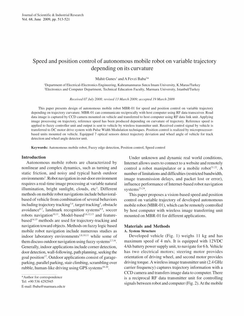
Developed vehicle (Fig. 1) weighs 11 kg and has
maximum speed of 4 m/s. It is equipped with 12VDC
4Ah battery power supply unit, to navigate for 6 h. Vehicle
has two electrical motors; steering motor provides
orientation of driving wheel, and second motor provides
driving torque. A wireless image transmitter unit (2.4 GHz
carrier frequency) captures trajectory information with a
CCD camera and transfers image data to computer. There
is a reciprocal RF data transmitter unit for controlling
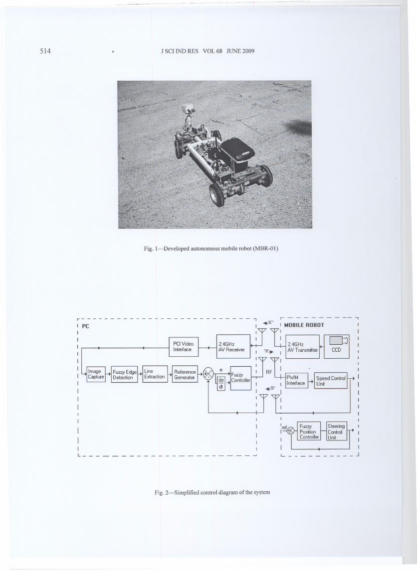
signals between robot and computer (Fig. 2). At the mobile
514 J SCI IND RES VOL 68 JUNE 2009
Fig. I-Developed autonomous mobile robot (MBR-Ol)
r - - - - - - - -- ,r---------------------------,PC
2.4GHzAV Receiver
MOBilE ROBOT
2.4GHzAV Transmitter
~CCD
Fig. 2-Simplified control diagram of the system
L _
GUNES & BABA: MOBILE ROBOT FOR SPEED AND POSITION CONTROL ON VARIABLE TRAJECTORY 515
,
----- ../ ../ :'
.:.
ICAMERA IMAGEI [FUZZY EDGE IMAGEI
'<1
INPUT FUNCTION 1- NEGl,~ur~~-POZo . ,-200 -100 0 100 20(}
Uiminance Difference
Fig. 3-Fuzzy edge detection rules
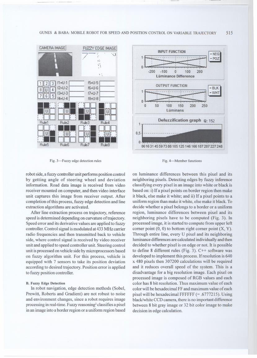
robot side, a fuzzy controller unit performs position controlby getting angle of steering wheel and deviationinformation. Road data image is received from videoreceiver mounted on computer, and then video interfaceunit captures this image from receiver output. Aftercompletion of this process, fuzzy edge detection and lineextraction algorithms are activated.
After line extraction process on trajectory, referencespeed is determined depending on curvature of trajectory.Speed error and its derivative values are applied to fuzzycontroller. Control signal is modulated at 433 MHz carrierradio frequencies and then transmitted back to vehicleside, where control signal is received by video receiverunit and applied to speed controller unit. Steering controlunit is processed on vehicle side by microprocessors basedon fuzzy algorithm unit. For this process, vehicle isequipped with 7 sensors to take its position deviationaccording to desired trajectory. Position error is appliedto fuzzy position controller.
B. Fuzzy Edge Detection
In robot navigation, edge detection methods (Sobel,Prewitt, Roberts and Gradient) are not robust to noiseand environment changes, since a robot requires imageprocessing in real-time. Fuzzy reasoning2 classifies a pixelin an image into a border region or a uniform region based
Defuzzification graph Q: 152
.,:~o " ..
001631455973881051251461601812072272481
Fig. 4-Member functions
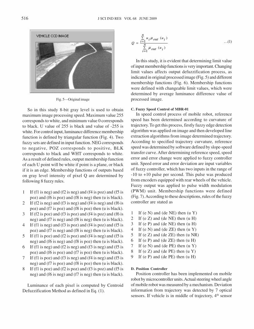
on luminance differences between this pixel and itsneighboring pixels. Detecting edges by fuzzy inferenceclassifying every pixel in an image into white or black isbased on: i) If a pixel points on border region then makeit black, else make it white; and ii) If a pixel points to auniform region than make it white, else make it black. Todecide whether a pixel belongs to a border or a uniformregion, luminance differences between pixel and itsneighboring pixels have to be computed (Fig. 3). Inprocessed image, it is started to compute from upper leftcomer point (0, 0) to bottom right comer point (X, Y).Through entire line, every U pixel and its neighboringluminance differences are calculated individually and thendecided to whether pixel is on edge or not. It is possibleto define 8 different rules (Fig. 3). C++ software wasdeveloped to implement this process. If resolution is 640x 480 pixels then 307200 calculations will be requiredand it reduces overall speed of the system. This is a
disadvantage for a big resolution imag~. Each pixel onprocessed image is composed of RGB values and eachcolor has 8 bit resolution. Thus maximum value of eachcolor will be hexadecimal FF and maximum value of each
pixel will be hexadecimal FFFFFF (= .6777215). Usingblack/white CCD camera, there is no important differencebetween 8 bit gray image or 32 bit color image to makedecision in edge calculation.
516 J SCI IND RES VOL 68 JUNE 2009
So in this study 8-bit gray level is used to obtain
maximum image processing speed. Maximum value 255
corresponds to white, and minimum value 0 corresponds
to black. U value of 255 is black and value of -255 is
white. For control input, luminance difference membership
function is defined by triangular function (Fig. 4). Two
fuzzy sets are defined in input function. NEG corresponds
to negative, POZ corresponds to positive, BLK
corresponds to black and WHT corresponds to white.
As a result of defined rules, output membership function
of each U point will be white if point is a plane, or black
if it is an edge. Membership functions of outputs based
on gray level intensity of pixel Q are determined by
following 8 fuzzy rules.
1 If (f1 is neg) and (f2 is neg) and (f4 is poz) and (f5 is
poz) and (f6 is poz) and (f8 is neg) then (u is black).
2 If (f2 is neg) and (f3 is neg) and (f4 is neg) and (f6 is
poz) and (f7 is poz) and (f8 is poz) then (u is black).
3 If (f2 is poz) and (f3 is poz) and (f4 is poz) and (f6 is
neg) and (f7 is neg) and (f8 is neg) then (u is black).
4 If (f1 is neg) and (f3 is poz) and (f4 is poz) and (f5 is
poz) and (f7 is neg) and (f8 is neg) then (u is black).
5 If (f1 is poz) and (f2 is poz) and (f4 is neg) and (f5 is
neg) and (f6 is neg) and (f8 is poz) then (u is black).
6 If (f1 is neg) and (f2 is neg) and (f3 is neg) and (f5 is
poz) and (f6 is poz) and (f7 is poz) then (u is black).
7 If (f1 is poz) and (f3 is neg) and (f4 is neg) and (f5 is
neg) and (f7 is poz) and (f8 is poz) then (u is black).
8 If (f1 is poz) and (f2 is poz) and (f3 is poz) and (f5 is
neg) and (f6 is neg) and (f7 is neg) then (u is black).
Luminance of each pixel is computed by Centroid
Defuzzification Method as defined in Eq. (1).
∑=
∑=
= n
iiuout
n
iiuoutiu
Q
1)(
1)(
µ
µ
…(1)
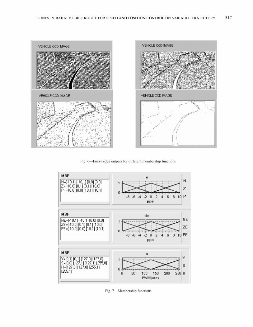
In this study, it is evident that determining limit value
of input membership functions is very important. Changing
limit values affects output defuzzification process, as
indicated in original processed image (Fig. 5) and different
membership functions (Fig. 6). Membership functions
were defined with changeable limit values, which were
determined by average luminance difference value of
processed image.
C. Fuzzy Speed Control of MBR-01
In speed control process of mobile robot, reference
speed has been determined according to curvature of
trajectory. To get this process, firstly fuzzy edge detection
algorithm was applied on image and then developed line
extraction algorithms from image determined trajectory.
According to specified trajectory curvature, reference
speed was determined by software defined by slope-speed
transfer curve. After determining reference speed, speed
error and error change were applied to fuzzy controller
unit. Speed error and error deviation are input variables
of fuzzy controller, which has two inputs in the range of
-10 to +10 pulse per second. This pulse was produced
from encoders equipped with rear wheels of the vehicle.
Fuzzy output was applied to pulse width modulation
(PWM) unit. Membership functions were defined
(Fig. 7). According to these descriptions, rules of the fuzzy
controller are stated as
1 If (e N) and (de NE) then (u Y)
2 If (e Z) and (de NE) then (u H)
3 If (e P) and (de NE) then (u H)
4 If (e N) and (de ZE) then (u Y)
5 If (e Z) and (de ZE) then (u NR)
6 If (e P) and (de ZE) then (u H)
7 If (e N) and (de PE) then (u Y)
8 If (e Z) and (de PE) then (u Y)
9 If (e P) and (de PE) then (u H)
D. Position Controller
Position controller has been implemented on mobile
robot by microcontroller units. Actual steering wheel angle
of mobile robot was measured by a mechanism. Deviation
information from trajectory was detected by 7 optical
sensors. If vehicle is in middle of trajectory, 4th sensor
Fig. 5—Original image
GUNES & BABA: MOBILE ROBOT FOR SPEED AND POSITION CONTROL ON VARIABLE TRAJECTORY 517
Fig. 6—Fuzzy edge outputs for different membership functions
Fig. 7—Membership functions
518 J SCI IND RES VOL 68 JUNE 2009
detects white stripe. When vehicle moves to right side,
white strip is detected by 3rd, 2nd and 1st sensors. Similarly,
when vehicle moves to left side, white strip is detected
by 5th, 6th and 7th number of sensors, respectively. If
vehicle passes through all sensors, robot keeps last sensor
information so vehicle moves to opposite direction.
Microcontroller board on vehicle scans white strip
detectors continuously and saves its status in memory to
learn vehicle position. This information gives vehicle
deviation from trajectory. If vehicle loses trajectory, last
sensor information in memory is taken into consideration.
Reference designator produces a reference steering angle
according to received position errors. Reference angle is
determined according to information of sensors.
• If (Position=1) Then (Angle 45°)
• If (Position=2) Then (Angle 22.5°)
• If (Position=3) Then (Angle 12.5°)
• If (Position=4) Then (Angle 0°)
• If (Position=5) Then (Angle -12.5°)
• If (Position=6) Then (Angle -22.5°)
• If (Position=7) Then (Angle -45°)
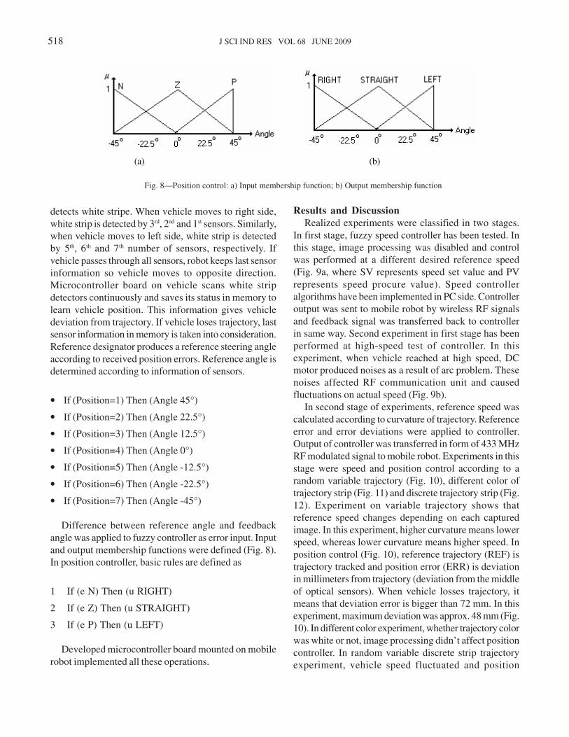
Difference between reference angle and feedback
angle was applied to fuzzy controller as error input. Input
and output membership functions were defined (Fig. 8).
In position controller, basic rules are defined as
1 If (e N) Then (u RIGHT)
2 If (e Z) Then (u STRAIGHT)
3 If (e P) Then (u LEFT)
Developed microcontroller board mounted on mobile
robot implemented all these operations.
Results and Discussion
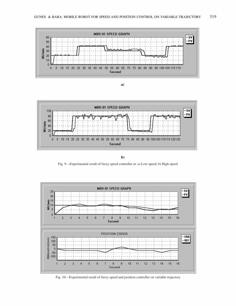
Realized experiments were classified in two stages.
In first stage, fuzzy speed controller has been tested. In
this stage, image processing was disabled and control
was performed at a different desired reference speed
(Fig. 9a, where SV represents speed set value and PV
represents speed procure value). Speed controller
algorithms have been implemented in PC side. Controller
output was sent to mobile robot by wireless RF signals
and feedback signal was transferred back to controller
in same way. Second experiment in first stage has been
performed at high-speed test of controller. In this
experiment, when vehicle reached at high speed, DC
motor produced noises as a result of arc problem. These
noises affected RF communication unit and caused
fluctuations on actual speed (Fig. 9b).
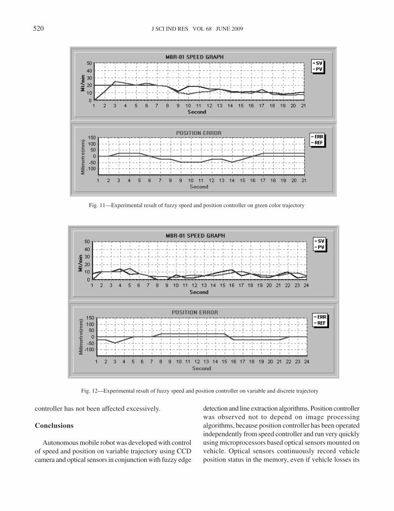
In second stage of experiments, reference speed was
calculated according to curvature of trajectory. Reference
error and error deviations were applied to controller.
Output of controller was transferred in form of 433 MHz
RF modulated signal to mobile robot. Experiments in this
stage were speed and position control according to a
random variable trajectory (Fig. 10), different color of
trajectory strip (Fig. 11) and discrete trajectory strip (Fig.
12). Experiment on variable trajectory shows that
reference speed changes depending on each captured
image. In this experiment, higher curvature means lower
speed, whereas lower curvature means higher speed. In
position control (Fig. 10), reference trajectory (REF) is
trajectory tracked and position error (ERR) is deviation
in millimeters from trajectory (deviation from the middle
of optical sensors). When vehicle losses trajectory, it
means that deviation error is bigger than 72 mm. In this
experiment, maximum deviation was approx. 48 mm (Fig.
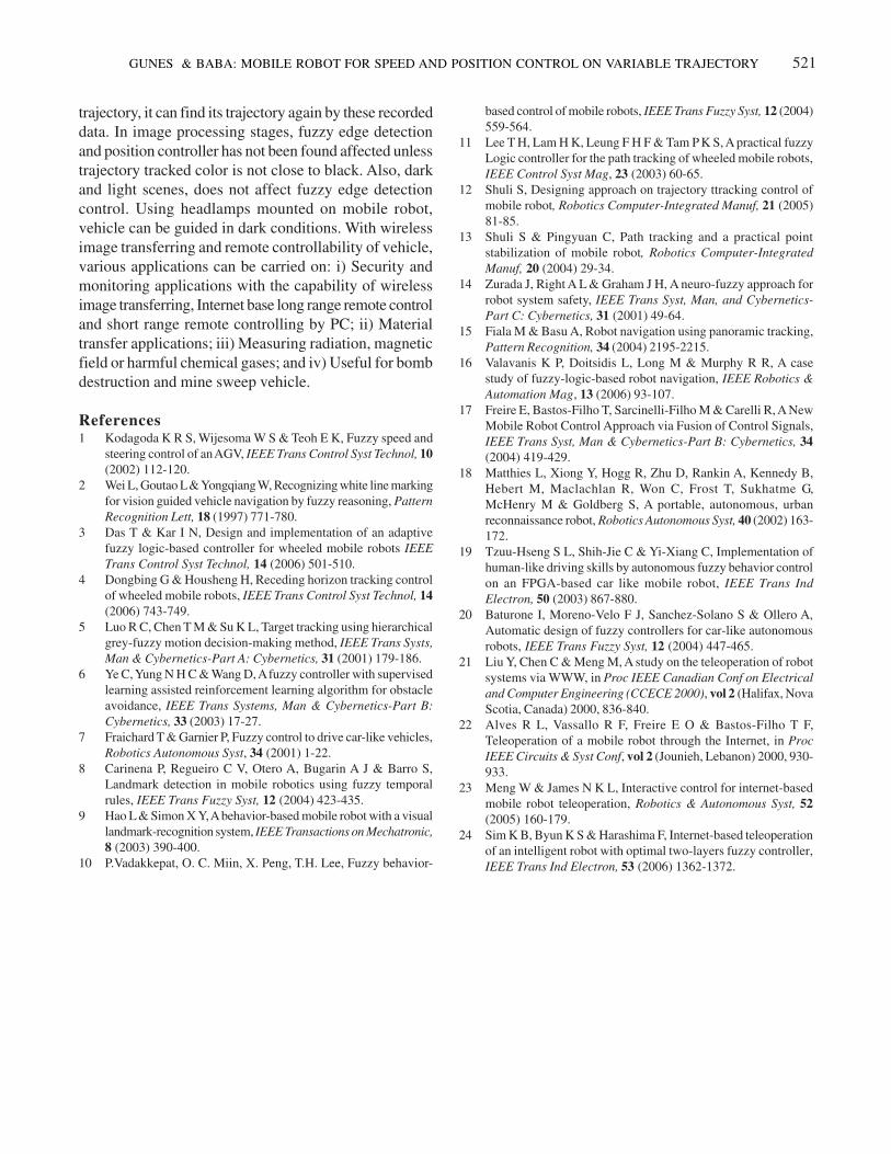
10). In different color experiment, whether trajectory color
was white or not, image processing didn’t affect position
controller. In random variable discrete strip trajectory
experiment, vehicle speed fluctuated and position
(a) (b)
Fig. 8—Position control: a) Input membership function; b) Output membership function
GUNES & BABA: MOBILE ROBOT FOR SPEED AND POSITION CONTROL ON VARIABLE TRAJECTORY 519
a)
b)
Fig. 9—Experimental result of fuzzy speed controller at: a) Low speed; b) High speed
Fig. 10—Experimental result of fuzzy speed and position controller on variable trajectory
520 J SCI IND RES VOL 68 JUNE 2009
controller has not been affected excessively.
Conclusions
Autonomous mobile robot was developed with control
of speed and position on variable trajectory using CCD
camera and optical sensors in conjunction with fuzzy edge
detection and line extraction algorithms. Position controller
was observed not to depend on image processing
algorithms, because position controller has been operated
independently from speed controller and run very quickly
using microprocessors based optical sensors mounted on
vehicle. Optical sensors continuously record vehicle
position status in the memory, even if vehicle losses its
Fig. 11—Experimental result of fuzzy speed and position controller on green color trajectory
Fig. 12—Experimental result of fuzzy speed and position controller on variable and discrete trajectory
GUNES & BABA: MOBILE ROBOT FOR SPEED AND POSITION CONTROL ON VARIABLE TRAJECTORY 521
trajectory, it can find its trajectory again by these recorded
data. In image processing stages, fuzzy edge detection
and position controller has not been found affected unless
trajectory tracked color is not close to black. Also, dark
and light scenes, does not affect fuzzy edge detection
control. Using headlamps mounted on mobile robot,
vehicle can be guided in dark conditions. With wireless
image transferring and remote controllability of vehicle,
various applications can be carried on: i) Security and
monitoring applications with the capability of wireless
image transferring, Internet base long range remote control
and short range remote controlling by PC; ii) Material
transfer applications; iii) Measuring radiation, magnetic
field or harmful chemical gases; and iv) Useful for bomb
destruction and mine sweep vehicle.
References1 Kodagoda K R S, Wijesoma W S & Teoh E K, Fuzzy speed and
steering control of an AGV, IEEE Trans Control Syst Technol, 10
(2002) 112-120.
2 Wei L, Goutao L & Yongqiang W, Recognizing white line marking
for vision guided vehicle navigation by fuzzy reasoning, Pattern
Recognition Lett, 18 (1997) 771-780.
3 Das T & Kar I N, Design and implementation of an adaptive
fuzzy logic-based controller for wheeled mobile robots IEEE
Trans Control Syst Technol, 14 (2006) 501-510.
4 Dongbing G & Housheng H, Receding horizon tracking control
of wheeled mobile robots, IEEE Trans Control Syst Technol, 14
(2006) 743-749.
5 Luo R C, Chen T M & Su K L, Target tracking using hierarchical
grey-fuzzy motion decision-making method, IEEE Trans Systs,
Man & Cybernetics-Part A: Cybernetics, 31 (2001) 179-186.
6 Ye C, Yung N H C & Wang D, A fuzzy controller with supervised
learning assisted reinforcement learning algorithm for obstacle
avoidance, IEEE Trans Systems, Man & Cybernetics-Part B:
Cybernetics, 33 (2003) 17-27.
7 Fraichard T & Garnier P, Fuzzy control to drive car-like vehicles,
Robotics Autonomous Syst, 34 (2001) 1-22.
8 Carinena P, Regueiro C V, Otero A, Bugarin A J & Barro S,
Landmark detection in mobile robotics using fuzzy temporal
rules, IEEE Trans Fuzzy Syst, 12 (2004) 423-435.
9 Hao L & Simon X Y, A behavior-based mobile robot with a visual
landmark-recognition system, IEEE Transactions on Mechatronic,
8 (2003) 390-400.
10 P.Vadakkepat, O. C. Miin, X. Peng, T.H. Lee, Fuzzy behavior-
based control of mobile robots, IEEE Trans Fuzzy Syst, 12 (2004)
559-564.
11 Lee T H, Lam H K, Leung F H F & Tam P K S, A practical fuzzy
Logic controller for the path tracking of wheeled mobile robots,
IEEE Control Syst Mag, 23 (2003) 60-65.
12 Shuli S, Designing approach on trajectory ttracking control of
mobile robot, Robotics Computer-Integrated Manuf, 21 (2005)
81-85.
13 Shuli S & Pingyuan C, Path tracking and a practical point
stabilization of mobile robot, Robotics Computer-Integrated
Manuf, 20 (2004) 29-34.
14 Zurada J, Right A L & Graham J H, A neuro-fuzzy approach for
robot system safety, IEEE Trans Syst, Man, and Cybernetics-
Part C: Cybernetics, 31 (2001) 49-64.
15 Fiala M & Basu A, Robot navigation using panoramic tracking,
Pattern Recognition, 34 (2004) 2195-2215.
16 Valavanis K P, Doitsidis L, Long M & Murphy R R, A case
study of fuzzy-logic-based robot navigation, IEEE Robotics &
Automation Mag, 13 (2006) 93-107.
17 Freire E, Bastos-Filho T, Sarcinelli-Filho M & Carelli R, A New
Mobile Robot Control Approach via Fusion of Control Signals,
IEEE Trans Syst, Man & Cybernetics-Part B: Cybernetics, 34
(2004) 419-429.
18 Matthies L, Xiong Y, Hogg R, Zhu D, Rankin A, Kennedy B,
Hebert M, Maclachlan R, Won C, Frost T, Sukhatme G,
McHenry M & Goldberg S, A portable, autonomous, urban
reconnaissance robot, Robotics Autonomous Syst, 40 (2002) 163-
172.
19 Tzuu-Hseng S L, Shih-Jie C & Yi-Xiang C, Implementation of
human-like driving skills by autonomous fuzzy behavior control
on an FPGA-based car like mobile robot, IEEE Trans Ind
Electron, 50 (2003) 867-880.
20 Baturone I, Moreno-Velo F J, Sanchez-Solano S & Ollero A,
Automatic design of fuzzy controllers for car-like autonomous
robots, IEEE Trans Fuzzy Syst, 12 (2004) 447-465.
21 Liu Y, Chen C & Meng M, A study on the teleoperation of robot
systems via WWW, in Proc IEEE Canadian Conf on Electrical
and Computer Engineering (CCECE 2000), vol 2 (Halifax, Nova
Scotia, Canada) 2000, 836-840.
22 Alves R L, Vassallo R F, Freire E O & Bastos-Filho T F,
Teleoperation of a mobile robot through the Internet, in Proc
IEEE Circuits & Syst Conf, vol 2 (Jounieh, Lebanon) 2000, 930-
933.
23 Meng W & James N K L, Interactive control for internet-based
mobile robot teleoperation, Robotics & Autonomous Syst, 52
(2005) 160-179.
24 Sim K B, Byun K S & Harashima F, Internet-based teleoperation
of an intelligent robot with optimal two-layers fuzzy controller,
IEEE Trans Ind Electron, 53 (2006) 1362-1372.