Spectrum sharing in 28 GHz band - EMC Europe · Spectrum sharing in 28 GHz band Feasibility of 5G...
21
© 2016 Nokia 1 Spectrum sharing in 28 GHz band Feasibility of 5G and FSS co-existence Presenter: Dr. Fabiano Chaves Contributors: Eugene Visotsky, Kamil Bechta, Prakash Moorut EMC 2016
-
Upload
nguyendung -
Category
Documents
-
view
219 -
download
1
Transcript of Spectrum sharing in 28 GHz band - EMC Europe · Spectrum sharing in 28 GHz band Feasibility of 5G...

© 2016 Nokia1
Spectrum sharing in 28 GHz bandFeasibility of 5G and FSS co-existence
Presenter: Dr. Fabiano Chaves
Contributors: Eugene Visotsky, Kamil Bechta, Prakash Moorut
EMC 2016

© 2016 Nokia2
5G/FSS co-existence in the 28 GHz band
The 28 GHz band
Fixed Satellite Service (FSS) as incumbent globally
Earth-to-space gateway-type services (UL) in USA (27.5 GHz – 28.35 GHz)
Nokia’s activities in the 28 GHz band
5G/FSS co-existence studies with USA operators (Verizon Wireless, AT&T, T-Mobile US)
Contribution to Federal Communication Commission’s (FCC) rules on 28 GHz published in July 2016
Results presented here were contributed to 3 filings with FCC
Background
Although focused on USA, work could be leveraged worldwide to open the 28 GHz band for 5G

© 2016 Nokia3
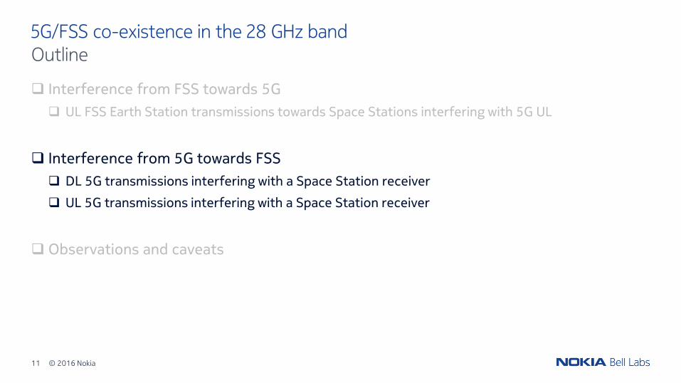
5G/FSS co-existence in the 28 GHz band
Interference from FSS towards 5G
UL FSS Earth Station transmissions towards Space Stations interfering with 5G UL
Interference from 5G towards FSS
DL 5G transmissions interfering with a Space Station receiver
UL 5G transmissions interfering with a Space Station receiver
Observations and caveats
Outline
© 2016 Nokia4
5G/FSS co-existence in the 28 GHz band
Interference from FSS towards 5G
UL FSS Earth Station transmissions towards Space Stations interfering with 5G UL
Interference from 5G towards FSS
DL 5G transmissions interfering with a Space Station receiver
UL 5G transmissions interfering with a Space Station receiver
Observations and caveats
Outline
© 2016 Nokia5
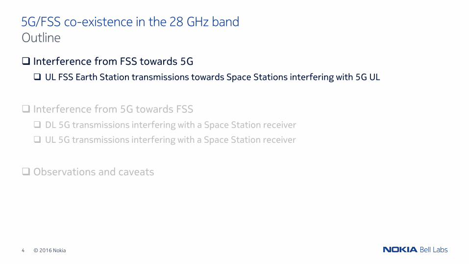
5G/FSS co-existence in the 28 GHz band5G system layout example (7 sites)
FSS Transmitter
AP nearest to the FSS Earth Station (‘Victim’ AP)
UEs (90 UEs per AP)
System layout stats:AP density = 29 APs/km2
ISD = 200 m
5G APs (3 sectors)
© 2016 Nokia6
5G/FSS co-existence in the 28 GHz band
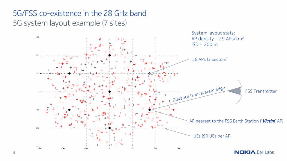
Link level protection criterion
Results are generated for 𝑇𝐻 = −12.2,−6, and 0 dB (from VzW and AT&T)
System level protection criterion
Minimum distance between an FSS Earth Station and the nearest 5G AP, such that 95% of the DL/UL links attached to the nearest 5G AP are “protected”
Positioning of FSS Earth Station relative to the 5G system
FSS Earth Station is pointed at the center of the 5G system layout
Preliminaries: 5G protection criterion
A 5G link (DL or UL) is “protected” from FSS Earth Station interference if:
𝐼𝐹𝑆𝑆 𝑁𝑡ℎ𝑒𝑟𝑚𝑎𝑙 < 𝑇𝐻 (𝑑𝐵),
where 𝑁𝑡ℎ𝑒𝑟𝑚𝑎𝑙 includes NF (5 dB)
© 2016 Nokia7
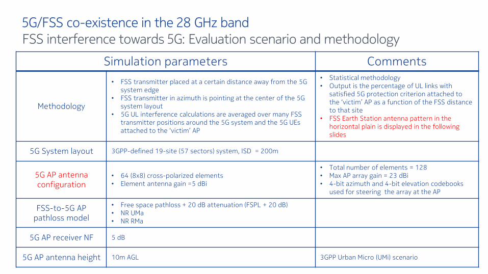
5G/FSS co-existence in the 28 GHz bandFSS interference towards 5G: Evaluation scenario and methodology
Simulation parameters Comments
Methodology
• FSS transmitter placed at a certain distance away from the 5G system edge
• FSS transmitter in azimuth is pointing at the center of the 5G system layout
• 5G UL interference calculations are averaged over many FSS transmitter positions around the 5G system and the 5G UEs attached to the ‘victim’ AP
• Statistical methodology • Output is the percentage of UL links with
satisfied 5G protection criterion attached to the ‘victim’ AP as a function of the FSS distance to that site
• FSS Earth Station antenna pattern in the horizontal plain is displayed in the following slides
5G System layout 3GPP-defined 19-site (57 sectors) system, ISD = 200m
5G AP antenna configuration
• 64 (8x8) cross-polarized elements • Element antenna gain =5 dBi
• Total number of elements = 128• Max AP array gain = 23 dBi• 4-bit azimuth and 4-bit elevation codebooks
used for steering the array at the AP
FSS-to-5G AP pathloss model
• Free space pathloss + 20 dB attenuation (FSPL + 20 dB)• NR UMa• NR RMa
5G AP receiver NF 5 dB
5G AP antenna height 10m AGL 3GPP Urban Micro (UMi) scenario

© 2016 Nokia8
5G/FSS co-existence in the 28 GHz bandFSS interference towards 5G: Modeling
FSS Earth Station pattern in the azimuth plane
FSS Earth Station Parameters Value
EIRP density towards horizon (dBm/MHz)12.2 (Class 1)24.1 (Class 2)48.0 (Class 3)
Antenna height 10m AGL
5G antenna array pattern

© 2016 Nokia9
5G/FSS co-existence in the 28 GHz bandFSS interference towards 5G: Results summary
Observations
Co-existence results sensitive to system protection thresholds
Range of coordination distances dependent upon the earth station class type
Earth Station ClassRequired UL Protection Distance (FSPL + 20 dB)
𝑇𝐻 = −12.2 𝑑𝐵 𝑇𝐻 = −6 𝑑𝐵 𝑇𝐻 = 0 𝑑𝐵
Class 1 < 50 m < 50 m < 50 m
Class 2 2000 m 400 m < 50 m
Class 3 70 km 28 km 15 km

© 2016 Nokia10
5G/FSS co-existence in the 28 GHz bandFSS interference towards 5G: Results summary
Observations
Co-existence results sensitive to propagation models
UMa / RMa
28 km15 km
FSPL + 20 dB Class 3 Earth Stations
Max. protection distance ≈ 5 km!
© 2016 Nokia11
5G/FSS co-existence in the 28 GHz band
Interference from FSS towards 5G
UL FSS Earth Station transmissions towards Space Stations interfering with 5G UL
Interference from 5G towards FSS
DL 5G transmissions interfering with a Space Station receiver
UL 5G transmissions interfering with a Space Station receiver
Observations and caveats
Outline
© 2016 Nokia12
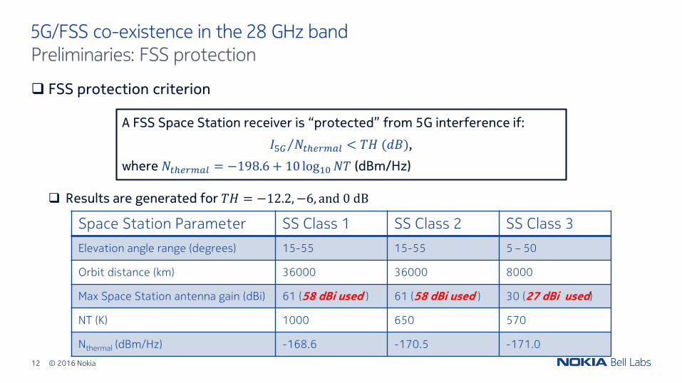
5G/FSS co-existence in the 28 GHz band
FSS protection criterion
Results are generated for 𝑇𝐻 = −12.2,−6, and 0 dB
Preliminaries: FSS protection
A FSS Space Station receiver is “protected” from 5G interference if:
𝐼5𝐺 𝑁𝑡ℎ𝑒𝑟𝑚𝑎𝑙 < 𝑇𝐻 (𝑑𝐵),
where 𝑁𝑡ℎ𝑒𝑟𝑚𝑎𝑙 = −198.6 + 10 log10𝑁𝑇 (dBm/Hz)
Space Station Parameter SS Class 1 SS Class 2 SS Class 3
Elevation angle range (degrees) 15-55 15-55 5 – 50
Orbit distance (km) 36000 36000 8000
Max Space Station antenna gain (dBi) 61 (58 dBi used ) 61 (58 dBi used ) 30 (27 dBi used)
NT (K) 1000 650 570
Nthermal (dBm/Hz) -168.6 -170.5 -171.0

© 2016 Nokia13
5G/FSS co-existence in the 28 GHz band5G interference towards FSS: Evaluation scenario and methodology (5G DL)
Simulation parameters Comments
Methodology
• Average receiver power (dBm/Hz) per sector is computed at the space station receiver
• Average receive power is calculated by averaging over all DL transmissions in the system
• Given an interference protection criterion, this can be used to compute the number of simultaneously active sectors
• Needs to be translated to AP density under certain assumptions
5G System layout 3GPP-defined 19-site (57 sectors) system, ISD = 200m
EIRP = 62 dBm/100 MHz5G AP antenna configuration
• 64 (8x8) cross-polarized elements • Element antenna gain =5 dBi• 6 degree mechanical downtilt• 16 horizontal/vertical beams with side-lobe control
• Total number of elements = 128• Max AP array gain = 23 dBi• Peak-to-sidelobe ratio = 30 dB
EIRP = 75 dBm/100 MHz5G AP antenna configuration
• 256 (16x16) cross-polarized elements • Element antenna gain =5 dBi • 6 degree mechanical downtilt• 16 horizontal/vertical beams with side-lobe control
• Total number of elements = 512• Max AP array gain = 29 dBi • Peak-to-sidelobe ratio = 30 dB
5G AP-to-FSS (space station) pathloss model
• NLoS: Free space pathloss + 20 dB + 4 dB • LoS: Free space pathloss + 4 dB
• 20 dB models NLoS clutter and vegetationlosses
• 4 dB models 1 dB atmospheric loss + 3 dB polarization loss
5G AP TX power• 39 dBm/100 MHz/per sector (EIRP = 62 dBm/100 MHz)• 46 dBm/100 MHz/per sector (EIRP = 75dBm/100 MHz)

© 2016 Nokia14
5G/FSS co-existence in the 28 GHz band5G interference towards FSS: Results summary (5G DL)
Class-3 min elevation angle = 50
Class-1 and Class-2 min elevation angle = 150
Average 5G AP antenna array discrimination towards satellite
5G antenna array pattern
© 2016 Nokia15
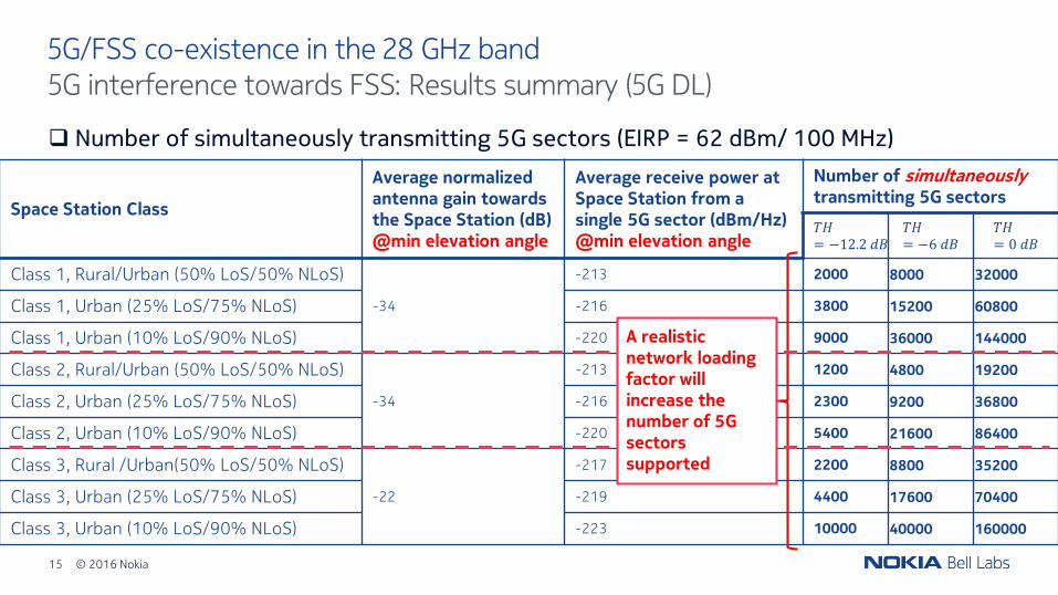
5G/FSS co-existence in the 28 GHz band5G interference towards FSS: Results summary (5G DL)
Number of simultaneously transmitting 5G sectors (EIRP = 62 dBm/ 100 MHz)
Space Station Class
Average normalized antenna gain towards the Space Station (dB)@min elevation angle
Average receive power at Space Station from a single 5G sector (dBm/Hz)@min elevation angle
Number of simultaneouslytransmitting 5G sectors
𝑇𝐻= −12.2 𝑑𝐵
𝑇𝐻= −6 𝑑𝐵
𝑇𝐻= 0 𝑑𝐵
Class 1, Rural/Urban (50% LoS/50% NLoS)
-34
-213 2000 8000 32000
Class 1, Urban (25% LoS/75% NLoS) -216 3800 15200 60800
Class 1, Urban (10% LoS/90% NLoS) -220 9000 36000 144000
Class 2, Rural/Urban (50% LoS/50% NLoS)
-34
-213 1200 4800 19200
Class 2, Urban (25% LoS/75% NLoS) -216 2300 9200 36800
Class 2, Urban (10% LoS/90% NLoS) -220 5400 21600 86400
Class 3, Rural /Urban(50% LoS/50% NLoS)
-22
-217 2200 8800 35200
Class 3, Urban (25% LoS/75% NLoS) -219 4400 17600 70400
Class 3, Urban (10% LoS/90% NLoS) -223 10000 40000 160000
A realistic network loading factor will increase the number of 5G sectors supported
© 2016 Nokia16
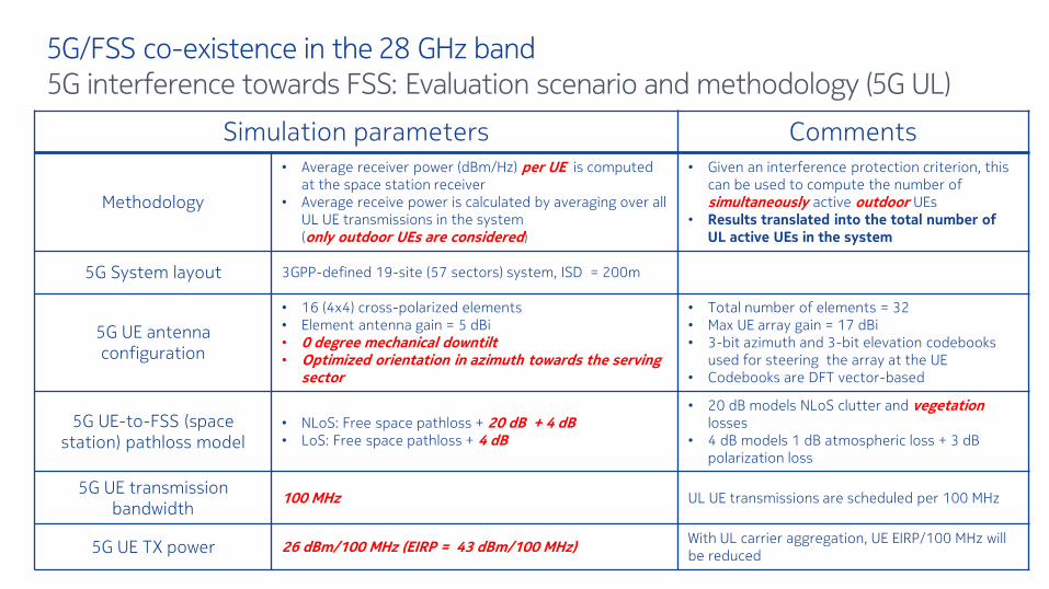
5G/FSS co-existence in the 28 GHz band5G interference towards FSS: Evaluation scenario and methodology (5G UL)
Simulation parameters Comments
Methodology
• Average receiver power (dBm/Hz) per UE is computed at the space station receiver
• Average receive power is calculated by averaging over all UL UE transmissions in the system (only outdoor UEs are considered)
• Given an interference protection criterion, this can be used to compute the number of simultaneously active outdoor UEs
• Results translated into the total number of UL active UEs in the system
5G System layout 3GPP-defined 19-site (57 sectors) system, ISD = 200m
5G UE antenna configuration
• 16 (4x4) cross-polarized elements • Element antenna gain = 5 dBi• 0 degree mechanical downtilt• Optimized orientation in azimuth towards the serving
sector
• Total number of elements = 32• Max UE array gain = 17 dBi• 3-bit azimuth and 3-bit elevation codebooks
used for steering the array at the UE • Codebooks are DFT vector-based
5G UE-to-FSS (space station) pathloss model
• NLoS: Free space pathloss + 20 dB + 4 dB • LoS: Free space pathloss + 4 dB
• 20 dB models NLoS clutter and vegetationlosses
• 4 dB models 1 dB atmospheric loss + 3 dB polarization loss
5G UE transmission bandwidth
100 MHz UL UE transmissions are scheduled per 100 MHz
5G UE TX power 26 dBm/100 MHz (EIRP = 43 dBm/100 MHz)With UL carrier aggregation, UE EIRP/100 MHz will be reduced
© 2016 Nokia17
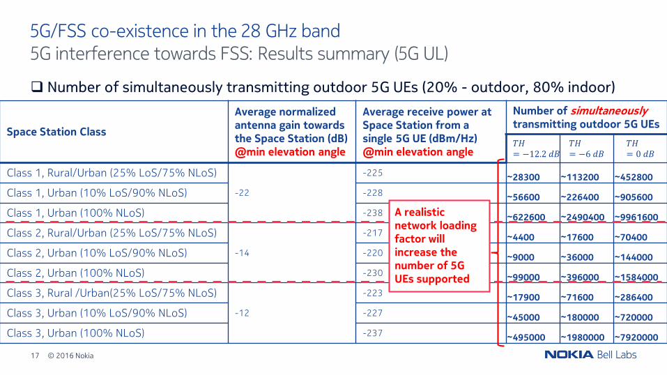
5G/FSS co-existence in the 28 GHz band5G interference towards FSS: Results summary (5G UL)
Number of simultaneously transmitting outdoor 5G UEs (20% - outdoor, 80% indoor)
Space Station Class
Average normalized antenna gain towards the Space Station (dB)@min elevation angle
Average receive power at Space Station from a single 5G UE (dBm/Hz)@min elevation angle
Number of simultaneouslytransmitting outdoor 5G UEs
𝑇𝐻= −12.2 𝑑𝐵
𝑇𝐻= −6 𝑑𝐵
𝑇𝐻= 0 𝑑𝐵
Class 1, Rural/Urban (25% LoS/75% NLoS)
-22
-225 ~28300 ~113200 ~452800
Class 1, Urban (10% LoS/90% NLoS) -228 ~56600 ~226400 ~905600
Class 1, Urban (100% NLoS) -238 ~622600 ~2490400 ~9961600
Class 2, Rural/Urban (25% LoS/75% NLoS)
-14
-217 ~4400 ~17600 ~70400
Class 2, Urban (10% LoS/90% NLoS) -220 ~9000 ~36000 ~144000
Class 2, Urban (100% NLoS) -230 ~99000 ~396000 ~1584000
Class 3, Rural /Urban(25% LoS/75% NLoS)
-12
-223 ~17900 ~71600 ~286400
Class 3, Urban (10% LoS/90% NLoS) -227 ~45000 ~180000 ~720000
Class 3, Urban (100% NLoS) -237 ~495000 ~1980000 ~7920000
A realistic network loading factor will increase the number of 5G UEs supported

© 2016 Nokia18
5G/FSS co-existence in the 28 GHz band
Interference from FSS towards 5G
UL FSS Earth Station transmissions towards Space Stations interfering with 5G UL
Interference from 5G towards FSS
DL 5G transmissions interfering with a Space Station receiver
UL 5G transmissions interfering with a Space Station receiver
Observations and caveats
Outline

© 2016 Nokia19
5G/FSS co-existence in the 28 GHz band
Co-existence analysis is sensitive to assumptions and parameters
Path loss models
FSS 5G interference: NLOS channel conditions result in much smaller protection distances
Protection criteria
5G FSS interference: I/N = -12 dB is an extremely conservative protection criterion (FSS UL can sustain much higher I/N levels with litle detrimento to the FSS system performance)
I/N = -6 dB or 0 dB results in 4x or 16x increase in the number of simultaneously transmitting sectors or UEs!
Refinements to be considered on the co-existence analysis
5G DL
A realistic network loading factor
5G UL
Scheduling effects (only a few (< 4) UEs simultaneously transmitting per sector)
Power control, as UEs were assumed to transmit at maximum power
Observations and caveats
© 2016 Nokia20
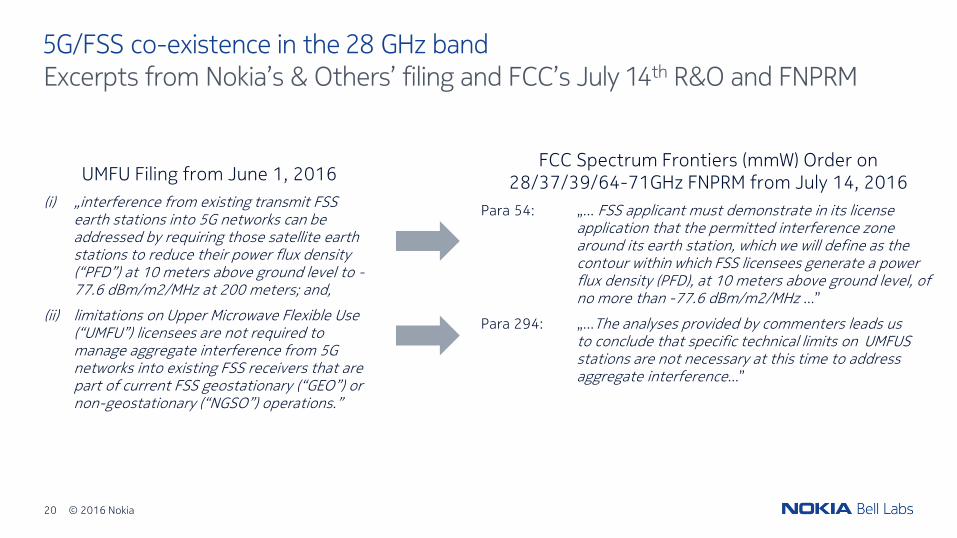
5G/FSS co-existence in the 28 GHz bandExcerpts from Nokia’s & Others’ filing and FCC’s July 14th R&O and FNPRM
UMFU Filing from June 1, 2016
(i) „interference from existing transmit FSS earth stations into 5G networks can be addressed by requiring those satellite earth stations to reduce their power flux density (“PFD”) at 10 meters above ground level to -77.6 dBm/m2/MHz at 200 meters; and,
(ii) limitations on Upper Microwave Flexible Use (“UMFU”) licensees are not required to manage aggregate interference from 5G networks into existing FSS receivers that are part of current FSS geostationary (“GEO”) or non-geostationary (“NGSO”) operations.”
FCC Spectrum Frontiers (mmW) Order on 28/37/39/64-71GHz FNPRM from July 14, 2016
Para 54: „... FSS applicant must demonstrate in its license application that the permitted interference zone around its earth station, which we will define as the contour within which FSS licensees generate a power flux density (PFD), at 10 meters above ground level, of no more than -77.6 dBm/m2/MHz ...”
Para 294: „...The analyses provided by commenters leads us to conclude that specific technical limits on UMFUS stations are not necessary at this time to address aggregate interference...”