SPECIFICATIONS - TxDPS...SPECIFICATIONS STATE OF TEXAS SCHOOL BUSES NO. 070 - SB - 92 1992 EFFECTIVE...
89
SPECIFICATIONS STATE OF TEXAS SCHOOL BUSES NO. 070 - SB - 92 1992 EFFECTIVE JANUARY 1, 1992 PREPARED JOINTLY BY GENERAL SERVICES COMMISSION TEXAS EDUCATION AGENCY DEPARTMENT OF PUBLIC SAFETY
Transcript of SPECIFICATIONS - TxDPS...SPECIFICATIONS STATE OF TEXAS SCHOOL BUSES NO. 070 - SB - 92 1992 EFFECTIVE...

SPECIFICATIONS STATE OF TEXAS
SCHOOL BUSES
NO. 070 - SB - 92
1992
EFFECTIVE
JANUARY 1, 1992
PREPARED JOINTLY BY
GENERAL SERVICES COMMISSION
TEXAS EDUCATION AGENCY
DEPARTMENT OF PUBLIC SAFETY
(J
TABLE OF CONTENTS
LIST OF FIGURES/TABLES ............................•••........................ ii
SECTION A- GENERAL INFORMATIONS, REQUIREMENTS, AND CONDITIONS ................ l
SECTION B - ORDERING INFORMATION ............................................. 10
SECTION c - 15-20 PASSENGER BODY REQUIREMENTS ................................ 23
SECTION D - 15-20 PASSENGER CHASSIS REQUIREMENTS ............................. 43
SECTION E - 24-83 PASSENGER BODY REQUIREMENTS ................................ 54
SECTION F - 24-83 PASSENGER CHASSIS REQUIREMENTS ............................. 82
SECTION G - WHEELCHAIR LIFT SPECIFICAITONS .................................. 106
SECTION H-AIR CONDITIONING SPECIFICATIONS ................................. lll
SECTION I- AVAILABILITY OF SPECIFICATONS ...........•....................... ll4
FORM FOR ASSISTANCE •••...•.•••......•••••....................... 115
THREE-MONTH TEST OF NEW SCHOOL BUS ENGINES ...................... ll7
COMPARISON OF SMALL SCHOOL BUS BODIES ••••..........•.•.••••...... 42
MAJOR COMPONENTS CHART (for Small School Buses) .....••.......... 119
MAJOR COMPONENTS CHART (for Large School Buses) ................. 120
GENERAL INDEX .......................................................... 121-127
1

LIST OF FIGURES and TABLES
FIGURES and TABLES
Fiq./Tabla No. Title Page No.
1 2 3 4 5 6 7 8 9
10 11 12 13 14 15 16 17 18 19 20 21 22 23 24 25 26 27 28 29
Physical Requirements, 15-20 Passenger Buses Comparison of 15-24 Passenger Buses 15-passenger School Bus Table 16-passenger School Bus Table 18-passenger School Bus Table 19-passenger School Bus Table 20-passenger School Bus Table Physical Requirements, 24-83 Passenger Buses Steel Requirements for School Bus Bodies One-piece Seat Cushion Physical Properties
Two-piece Seat Cushion Physical Properties 24-passenger School Bus Table 35-passenger Conventional School Bus Table 47-passenger Conventional School Bus Table 47-passenger F.C. School Bus Table 53-passenger Conventional School Bus Table 53-passenger F.C. School Bus Table 59-passenger Conventional School Bus Table 59-passenger F.C. School Bus Table 65-passenger Conventional School Bus Table 65-passenger F.C. Diesel School Bus Table 71-passenger SWB Conventional School Bus Table 71-passenger LWB Conventional School Bus Table 71-passenger F.C. Diesel School Bus Table 77-passenger Conventional School Bus Table 77-passenger F.C. Diesel School Bus Table 83-passenger F.C. Diesel (front engine) School Bus Table 83-passenger F.C. Diesel (rear engine) School Bus Table Air Conditioning ~n~um Requirements Table
ii
23 42 49 50 51 52 53 54 61 69 70 89 90 91 92 93 94 95 96 97 98 99
100 101 102 103 104 105 111

D'I'IIC!'IW DAft: January 01, 1992
A.l. ICOP&-
~ SP&C%F%CA~%0M
Ito. 070-SB-P2 Supersedes No. 070-SB-91
1.1 808 8%Z&S - Thia •ehool bus specification include• the Bdnimum requirements for fourteen sizes of school buses used by Texas Schools participating in the Foundation School Program. This •pecification covers the purchase of bus bodies and chassis separately as well as the purchase of complete •chool buses. The bus sizes ahall be designated in terms of passenger capacity (exclusive of the driver} as listed below for regular seating ( "CUACift" i.• ba••d apoa. Da~J..ozaa1 Mivb't aad '"'i.pt perc-nt..i.l• a.,.rA9•• •• .... c!.!'1.-d. b F .. ral R.iglntay Safety Proqr- S't.&Dclard Ro. 17. 8•• Par. 8.1.2.):
15* Passenger 16* Passenger 18* Passenger
19* Passenger 20* Passenger 24* Passenger
35* Passenger 47* Passenger 53* Passenger
59* Passenger 65* Passenger 71* Passenger
71* Paesenger(Long WB) 77*Passenger 83* Passenger
(Short KB)
*ROTa: Seating capacity will be reduced from the above whenever wheelchair positions and/or maximum seat spacing are specified for a given size bus (see Par. A.l.3 and Par. B.l.).
1.2. 808 ~PES - Each bus shall have seating arrangements for the capacities designated:
1.2.1. 1.5-pa•IHlDp:r bus shall be the van conversion or commercial cutaway semi-forward control type.
1.2.2. 16-p-..ap:r bus shall be the commercial cutaway semi-forward control type. 1.2.3. 11-paa...,p:r bus shall be the van conversion type. 1.2.4. 1t:l-pa•eeDp:r buo ahall be the commercial cutaway semi-forward control type. 1.2.5. 20-p••....-r bus shall be tbe stripped chassis semi-forward control type. 1.2.6. 2•-p••.-ztp:r bus a hall be the atripped chassis semi-forward control type. 1.2.7. 35-pa•Mt~apr bus shall be the conventional or semi-forward control type. 1.2.9. •7-pa•..,.pr bus shall be the conventional, forward*, or semi-forward control
type. 1.2.9. !53-p-8Uripr bus shall be the conventional, forward*, or semi-forward control
type. 1.2.10. 59-p-eeDpr bus a hall be the conventional, forwa::rcl*, or semi-forward control
type. 1.2.11. CS-pa•~r bus shall be the conventional, forward*, or aemi-forward control
type. 1.2.12. 71-pa•..a.v-r buo a hall be -the conventional, forward*, or aemi-forward control
type. 1.2.13. 77-p .. --.pr buo shall be the conventional, forward*, or •end-forward control
type. 1.2.14. u-. .. -!1"" bus shall be the forward control* transit type.
•Di.•••l oaly.
1.3. 8PZCXAL KD~T%0R 808&8 - Special education buses for impaired passengers may contain leas than 15 passenger and wheelchair positions combined, but not less than 10 passenger positions combined or they cannot be certified as achool buses. These vehicles, used for transporting special education school children, that contain fewer than 10 passenger positions are classified as Multipurpose Passenger Vehicles (MPVa) by the Federal Government. They will be designated by the State of Texas as "school buses" for the purposes of this specification. The State of Texas requires that MPVs used as school buses shall meet the same standards they would meet if built to accommodate 10 or more passengers even though they must be certified as Hultipurpose Passenger Vehicles.
1 03/2!/P2- Aa. 11- I••aed a-w pav-• 1-4,7-1,11-20,25-2C,3P-42,•P-52,
57-SI,CP-70,77-80,P!-100,111-112. 070-88-P2 Ol/Ol/P2

A.2. DD"IRI!'IORS -
2.1.
2.2. 2.3. 2.4. 2.5. 2.C.
2.7. 2.1. 2.P. 2.10. 2.11. 2.12.
2.13.
2.U. 2.15. 2.U. 2.17. 2.18. 2.1P. 2.20.
~BRAE means Amer~can Society of Beating, Refrigeration and Air Conditioning En9ineers. ARSI means American National Standar~ Institute. AsTN means American Society for Testing and Materials. BCI means Battery Council International. c~ •• ~on and QSC mean General Services Commission. CODYentLOD&1 Bu• means a •chool bus with all of the engine in front of the vindahield and the ••rvice or entrance door behind the front wheels. o.pa~ .. at of Rablio 8a~e~y and DPS ••an Texas Department of Public Safety. &duaatioa A9-DCY and ~ .. an Texas Education Agency. &PA mean• Onited States Environmental Protection Agency. FMVBS means Federal Motor Vehicle Safety Standarda. rederal at&Ddard Ro. 17 means Federal Highway Safety Program Standard Number 17. rorwa~d Coatro~ 8u• means a school bus with the steering whee1, pedals, instruments, and other driver contro1s mounted as far forward as possible, usua11y just behind the windshield. ~l of the engine is located behind the windshield, either at the front of the bus, or at the rear of the bus, or in between these positions. The service door is 1ocated forward of the front axle. Knee lpaa- means the horizontal distance from the front center of a seat back to the rear center of the seat back (or barrier) immediately ahead, measured at approximately 4 inches above the aeat cushion. M&ftuLactu~r means a fabricator of school buses, bodies, chassis, or components. MFV means a multipurpose passenger vehicle accommodating ten or less people. ftSSB means National Standards for School Buses (formerly National Minimum Standards). 8AZ means Society of Automotive Engineers. S~ means School Bus Manufacturer's Institute. SCAAN means a computer analysis of engine performance. 8.-1-forward Coatrol 8u• means a bus in which part of the engine is beneath and/or behind the windshield and beside the driver's seat.
2.21. VaDdor means a manufacturer's representative or dealer authorized to make sales and supply parts and •ervices in Texas.
2.22. VESC means Vehicle Equipment Safety Commission.
A.3. APPLICABLJ: SPJ:CIFICA!'IORS AND IDHDARDS -
3.1 F&D&RAL BXQBKA% SAFZTY PROQRAM I~ARD - School bus bodies and chassis shall meet or exceed the minimum requirements of this specification and shall also meet all applicable requirements of the Highway Safety Program Standard No. 17. ~1 requirements of this specification must be met unless they are in conflict with Standard No. 17 as it applies to school buses:
3.1.1. F.O.ral Bi.9hway 8d.ty Proqr- ft&Dclard. lfo. 17, Pllpi~ 'l"z'&Daport.ation Saf"aty -Supt. of Documents, U.S. Government Printing Office, Washington, D.C. 20402.
3.2. FID&RAL MOTOR VZBICL& &AFZTY S~ARDS - School bus bodies and chassis shall meet or exceed the minimum requirements of this specification and ahall also meet all applicable requirements of the r~ral MOtor V.bic~• Sa~•ty standarda (FNVSS). All requirements of this sp•cification must be met unless they are in conflict with the TMVSS as they apply to school buses:
3.2.1. red*r&l Motor V~ole ··~·ty ftaadarda CPUblio Law 8P-S63) - Superintendent of Documents, O.S. Government Printing Office, Washington, D.C. 20402:
(1) (2) (3) (4)
(5) (6) (7) (B) (9)
(10) (11) (12) (13) (14) (15) (16)
FMVSS No. FMVSS No. TMVSS No. FMVSS No.
FMVSS No. FMVSS No. FMVSS No. FMVSS No. !'MVSS No.
FMVSS No. FMVSS No. FMVSS No. FMVSS No. FMV'SS No. FHVSS No. FMVSS No.
103 105 108 111
121 125 205 208 209
210 217 220 221 222 301 302
- IU.Dda!U.elcl Def:co•t.I.D!J Ulcl Def~IO!J 8y.t-•. - 8rak••, 8yclraa1ic lerTioa, ... rpDcy and Parki.D9. - W.p•, a.flecrti"AA D.-via-•, and Aa•ociatad. &quil*-at. - Jt.arriaw JU.rror• - •••-ft9•r Car• and Nu.~tipuzpo••
P•••enger Vehiol••· - Air 8rak• lyrt... - Ba.•• aDd rraU•z-•. - WarDin9 DeYia-•.
QlasiD9 Material•. - Occupant Cra•h Protection. - l•at .. lt Aa..abli•• - ..... DV-r Car•, ~tipa~••
••••eDV•r Vehiol••, rraoka aDd au-•. - hat a.~t A..••Jibl.y ADahorap•. - Bu• Wi.Ddow Retention and R-leaaa. - School lhla Rol.l-OTer Prot.aat.J.on. - Sobool h• Body JoJ.nt St~Dgt.h. - lahool 8u• S•ati.D9 aDd Cra•h •rot.•ction. - Fuel ly.t .. Int-9r.l.ty. - r~-~llity of Iaterior llat•ri.al• - Paaaanpr Car•,
llaltipuq»a•• •••aa~~pr Vehia~ea, !'ruaka, aDd lhl•••.
2 070-IB-P2 01/01/P2

c
3.3. IIA!"'CJIHAL ft.AJU)AM)I rOR IC800L atJRI (IUD) - School bua bodies and chassis shall also meet or •xceed the current National Standarda for School Buaes (formerly National Minimum Standards) •xcept when those requirements are in cooflict with the requirements of this specification. In such cases, the requirements specified herein shall prevail:
3.3.1. ~ioaal ataadard. *or School Bu•••, 1PPO M.Tiaed ~~Lon, National Standarda Conference (May, 1990), National Safety Council, 425 North ~chigan Avenue, Chicago, Illinois 60611.
3.4. OT&Ka M&~l - ~ferences to other apecificationa, ataadarda, and teat aethods shall be to those in effect on the date of the Invitation for Biela. The following publications form a part of this specification to the extent apecified herein:
·.
3.4.1. ~r~oaa .. t~oD&l ltaadard. x..tLtat•, %ao. (ARII), 1430 Broadway, New York, NY 10018:
(1) ANSI Z26.1 - 8afa~y IUasiDg .. hd.ala fo&" Gl.ui.Dg llfto&" VaiU.alaa OperatLD9 OD LaDd 8i9bwaya, Safety Code for, including Supplement Z26.1a - 1969.
3.4.2. a-ri.oaa •l.7'f00d. Aa•ocd.e.UOD, P.O. Box 11700, Tac011a, Washington 98411:
(1) u.s. Plywood Standard PS 1-83.
3.4.3 • .a-rJ.oan loo.iety ~or h.t.Lag uad Mate1:'J.ala (AIITII), 1916 Race Street, Philadelphia, PA 19103:
(1) ASTM A 446
(2) ASTMA 525
(3) ASTM D 3574
(4) ASTMB 117 -
- Standard Specification for S~.t ~ .. 1, ZJ.ac Coat~ (Oa.l•u:a.iaed) by til. Bot DLp l'rooa.•, atZ'Octura.l (Phy•J.oal) Quality.
- Stan~ard Specification for GeDeEal a.quLr-.enta ~or at .. l aaa .. t, SJ.ac Coa~H (Oa.l•ani.aed.) ~ the Bot -Dip ProeM~•• .
- Standard Specification tor lt&Ddazd ~·et ~thod *or ~atJ.a9 C•llolar KaterJ.al• - Slab 8oaded Ud Molded Urethua• roaa. Standard Specification for ~tbod of Salt lpray (rog) !'oonbg.
3.4.4. -.d.aaD 8oo.iety of Bea~:Lag, a.fripratJ.oa uad Ail: CoDciJ.tioni.D9 bgia .. r•, Ioo. (ASBRA&), Circulation Department, 345 East 47th Street, New York, NY 10011:
(1} ASRRAE 16-69 - Methods of ~etiD; fo1:' RatiD9 of aooa Ai.r CODditioa-r•.
3.4.5. redaral. lli.gbway A.ctai.J:t,ietratioa, UDi.tecl Sta~•• Dqart:..at o~ rraaqortatLon, Superintendent of Documents, U.S. Government Printing Office, ftashington, DC 20402:
(1) Federal Highway Administration FP-85 - Standard Specifications for CODatruot.J.on of Jt.oacU and 8ri.c:l;-• Oil r•cl.ral .Ri9hway Projact•.
3.4.6. r.S.ral atuadar'Cbl - Superintendent of Documents, O.S. Government Printing Office, Washington, D.C. 20402:
(1) No. 595a - -Color•.
3. 4. 7. r.cleral ap.o.i.fJ.oat:J.OD• - Superintendent of Documents, 0. S. Covernmant Printing Office, Washington, D.C. 20402:
(1)
(2)
(3) (4) (5)
TT-C-490B
TT-C-520B
TT-E-489 v -~-2950 ZZ-H- 11D
- Cl--...dD9 ... t:.boc:LI aad l'~z.a1:8ent of ren:ou• lur~aoe• ror ~o Coat:J.a9.
- CoatJ.Dg• C-.po\UIId, tit:aaiDoaa, Sol~ l'ype Uaderbody, (ror Mbtor Vebi.ol••).
- &Daael, Alkyd, Olo•• (roJ: &xterJ.o1:' arad %Dte1:'i.oz IUZ'faoee) • - !"b.~ad, llylOD. - .. ~~iDg, Rabba&" Uld ViDyl.
3.4.8. lobool 8ae 11uudacta~1:'•' XDRi.tate (IIDII), &Dgb~i.D9 Cc.ai.tt .. , 7508 Ben Avon Road, Bethesda, Maryland 20817:
{l) SBMI Standard No. 001 - Standard Code for h.ti.ag' aad Rat.l.D9 Auto.oti .. ha - lla~ ...... ~iDg aDd V-il•~iDg &qaipo ... t.
3 070-8B-P2 01/01/P2

A. GDtDAL J:IU'O-TION, lti:Q0%-8, ARD CORDITIOIIS
3.4.9. 8oc~•ty o~ Aat~~ .. KDgioe•r•, lao. (aAZ), 400 Commonwealth Drive, Warrendale, Pennsylvania 15096:
(1) (2) (3) (4) (5) (6) (7) (B)
(9)
(10) (ll)
(11) (13)
SAE J20e SAE J377 SAE J383 SAE J514 SAE J516 SAE J517 SAE J561 SAE J5BB
SAE J639
SAE JBB7 SAE J994b
SAE J112B SAE J1133
- Coolaz~~t 8y.t.- Boa•• • - »•r~ora&Do• o~ V•~ol• ~rarr~o Boraa. -Motor Vehiol• a.at a.lt ADaboragea - O.aivn a.~dationa. - Bydraul~a tube r~ttiDg•. - Bydraulio Boae ritt~a. - Bydzaulio Bo••· - &l•atdaal Te..W.al• - &yalet ....S lpade oryp.. - ~rn 8iqaal Laapa for a•• on aotor ~ol•• ~••• thaD
2032 - J.a o..ral.l wi.ctUa.. - Safety Rracrtio.a for lleahanioal Vapor Coapreaaion a.fri~ration &quipaeat or ay.t.... Uaed to Cool Paaaan9•r C'*Paftaenta of Motor VelaJ.clea.
- 8obool Bua llanli.IUJ Laapa. - Alana - 8aakap - &le=t.rio - P•rfoEaaaoe, h.t., &Ad
App.U.oation. - Low r.aaion PrLaary Cable. - School Bua atop Aza.
3 ••. 10. S'l'A'l'& or CA.LirOARIA -
3.4.10.1. DEPT. OF CONSONZR AFFA%RS, 3485 Orange Grove Ave., North Highlands, CA 95660.
(1) Cal..ifornia 'l'ecbDJ.oal Bu1letJ.D 117, Section A, Part I, Seat Cushion Compression Test.
3 • • .11 . sn'l'll: or 'l'&XU -
3.4.11.1. ~LROAD C~SSION OF TEXAS, Liquefied Petroleum Gas Division, P.O. Box 12967, Austin TX 78711-2967:
(1) ~ation• ~or Caapre•••d Natural Oa• (November, 1990}, (2) Safety Rule•-Liquefied Petro~eua Qa• Di?i•ion (Nov., 1990)
3.4.11.2. TEXAS AXR CONTROL BOARD, 12124 Park Circle, Austin, TX 78753:
(1) Regulation IV {31 TAC CHAPTER 114), Control o~ Pollution froa MOtor Vehicle• (Rev. Aug. 30, 1991)
3 .•. 12. United stat•• KDTiroa.enta1 Proteatioa A9-ncy (&PA), Waterside Mall, 401 M Street, s.w., Hashinqton, D.C. 20460:
3 .•. 13. V.b.io1e &qa.ipa•a1:. 8a~ety C~••ion (VZSC), Suite 908, 1030 15th Street, N.W., Washington, D.C. 20005:
(1) VESC - R-galat~an S. (2) VESC - R-galat~aD 10.
A. • • G&RI:RAL IKFOIWATIOR ARil lti:QOJ:RDI&RTS -
•.1. •QU%»MZRT rRS~r%0R - Requirements and accessories, either standard or optional, furnished under this specification shall be installed by body, chassis, or product manufacturer except air conditioners, tachoqraphs, tachometers, and wheelchair lifts may be installed by authorized service Representatives. Installation of such items shall conform in strength, quality, and workmanship to the accepted standards of the industry.
•.2. MEW MODELS - Each bus body and bus chassis furnished under this specification shall be new school bus of the current year' a production or the latest improved model in current production. The bidder repre·sents that all units offered under this specification shall meet or exceed the minimum requirements specified herein •
... 3. ODCMJI:'l'KR DISCLOSUIUI: a'!rAftiCENT - The Truth in Mileage Act requires the sellinq dealer to furnish a complete odometer statement to the purchaser. This statement must be ~ complete and shall include mileaqe accrued at the point of delivery. In addition to ~ the signature of the seller/agent certifying the odometer reading, both the dealership and the name of the aqent shall be printed on the Odometer Disclosure Statement. (Completion of the Mileage Statement Portion of the MSO will satisfy this requirement.)
• 03/25/P2 - Cb~ by Aa. 11 070-BB-P2 Ol/01/P2

4.4. IKRVlCIRG AMD &QOIVPIHQ - All bus bodies, cbaaaia, or complete school bus units shall be completely assembled, adjusted, and all equipment installed. All parts not •pacifically mentioned herein which ara necessary to provide a complete school bus, buS body, or chassis shall be furnished by the successful bidder and said parts shall conform in strength, quality of materials, and workmanship to recognized industry engineering practices.
4.5. ~ GVWR a&LaeflOM - Tba requirements for gross vehicle weight ratings, gross axle weight ratings (front and rear), and tire aiza and load range for each aize chassis are apac~fied in Tab1e Noa. 3-7 and 12-28, and are minimum requirement•. These requirement• are for smal1 type school bus (15- through 20~asaenger}, conventional and semi-forward control type school buses (24- through 77-passengar), forward control type school bus (47- through 77-paaaenger), and a transit type school bus (83-passenger) with standard equipment. ~ add8d .. igbts of optioD&l equi~nt auab •• alt:enta'ti'Y'& faal etorap t.eDka, aizo ooJKU.t.ioaiDg, lugvap zoaaka, lifts fozo t.ba pbyaioal.ly i.llpaizoecl a.Ad ot.bezo Mavy ~aaozoi.ea --~ Dot. ooaaidered b e.t.abllebin9 t.M aapaait:y zoa'tiDga t:.o be -Z"tifiecl for t:l:le obaaaia. If additional optional equipment is ordered, which necessitates increased capacity ratings of either axles, springs, or tires, it is the responsibility of the vendor to furnish them so that proper certification can be made on the vehicle.
Par. A.4.5. is not applicable for chassis only which are used by the State of Texas for remounting of bus bodies.
A.S. BID a.ARDS - The Commission reserves the right to accept or reject any and all bids, in whole or in part, and to waive all technicalities when these actions are determined by the Commission to be in the beat interest of the State of Texas. Failure to receive a satisfactory chassis or body bid shall not prohibit the awarding of contracts to others by the Commission, when in the best interest of the State.
Ao C o aRTZFXCA!rXOR .uiD CCIIPLUlfCII -
6.1. BUS BODY WORK ORD&R- The work order which accompanies the bus body through the production line during the process of manufacture must show the re~atad Commission Purchase Order Number that was issued to the bus body company or the distributor. The work order must also show the appropriate item number of the purchase order or the nama of the schoo~. One copy of the work order must accompany the bus to its final destination.
Co2 o CKn'D"XCA'l'l:OR, ALL 8%DDDS - lly dglliAg tbo bJ.cl, tbo bJ.clcle"' -rt.l.fi•• that the equipment being offered meets or exceeds all requirements and conditions of this specification. Failure to comp~y with all the requirements and conditions of this specification will subject the bid to rejection.
t.3. C&RTIFICA!'IOR, aoccaiii'UL BIDDD - '!'be ,..DClozo (auoa.aa~ul bi~zo) auft a.rtJ..~y oa tbe faoe o~ tbe i.D?oioa that the equipment delivered meats or exceeds the requirements and conditions of this specification and that the equipment was manufactured in accordance with this specification. The burden of proof for compliance with this specification shall be the responsibility of the vendor, manufacturer, or both.
Co. o CJWI8U noDUC'l'XOR OIADD -
6.4.1. Attachment - On• copy of the production ordar (line setting ticket) listing both standard and optional equipment installed on the chassis must accompany the chassi• to which it pertain• upon de~ivery of the chassis to tba bus body manufacturer and to the final destination (receiving School District). The copy of this production order should be contained in a waterproof envelope and placed in the g~ove compartment, or it may be secured by other means which will assure positive attachment to the chassis (see Par. A.6.4.2. below). The production order shall be a printed form and not machine coded.
6.4.2. ~tarnative Plate - In lieu of the production order, the information required above may be stamped on a metal plata, either on the truck identification plate regu~arly furnished or on an additional p~ate. The identification plata(s) shall be attached to the chassis in a conspicuous p~ace and in an accessible position in order that it may be easily read.
6.4.3. Removal/Obliteration - The production order (line setting ticket} or chassis identification plata referred to above ahall not be removed from the chassis by the body manufacturer since it is for the information of the receiving school district. The truck identification plate shall not be obliterated when undercoating or paint ia applied to tba area where the plate ia mounted. The plata •ball not be mutilated or covered when installing equipment •uch as the heater, heater hoae, or electrical cables.
5 070-IB-•2 01/01/'2

C.5. LI~RATCRE ARD DRARZRQS - Each bidder shall furnish the following:
6.5.1. Drawings - The bidder shall have on file with the Commission, detailed ~•o.etria drawings of the bus body showing floor panels, aide posts, roof bows, bow-frames, strainers, longitudinal frame members, exterior panels, and front and rear end framing. Each component shall be identified in block form showing {first) the item number, (second) the type of steel, and {third) the decimal thickness of steel used in the construction. (Refer to Table No. 9 for ateel requirements on 24-paasen9er and larger capacity buses.)
6.5.2. Drawings, Number of - On construction items, one drawing will suffice; however, additional drawings shall be furnished on special items and changes or deviations from common construction whenever such change affects any size bus. All drawings submitted will be treated as confidential information. Drawings must be approved by the Commission.
6.5.3. Literature - The bidder shall have on file with the Commission, the latest pamphlets, brochures, and printed literature on the equipment the bidder proposes to furnish to this specification.
6.5.4. Metal Certification - The bidder shall have on fila with the Commission, a statement certifying that the metal used in Texas School Buses conforms to the National Standards for School Buses (NSSB) • NSSB requires galvanized steel to meet the requirements of the 1,000 hour salt spray test in accordance with ASTM Standard B 117 and shall not lose more than 10' of material by weight.
&.&. MaNOrACTORER'S ~~~or ORIGIN- The vendor (successful bidder) shall furnish the Commission with the manufacturer's Statement of Origin (Certi~icate o~ ~it~• will not ... t tbi• requir.aent). The manufacturer's New Vehicle Warranty and major component parts warranties (see Par. A.l0.4.) shall be furnished to the receiving school district. (See Par. A.7.6. for Pre-delivery Service requirements.) The ~ter atat .. ent required by law shall include the mileage accrued at the time of delivery to the school district.
,.7. ~ORARY LICENSE ~GS- Temporary (Red) License Tags shall be issued by the vendor for use with each new bus delivered (see Par. 8.4.2.).
A. 7. DELIVERY -
7.1. D&LrYZRX PROCSDOR& - The delivery of a bus to any specified destination may be made by any normal ~elivery procedure which the manufacturer or distributor utilizes (see ROTE below) • The bus body distributor must guarantee the equipment to be free of damage as a result of the type of delivery. If any damage is caused by or during delivery that can be established within six months after delivery to any school, then the school must be compensated for auch damage by the contractor. It shall be the obligation and responsibility of each body manufacturer to check and inspect each chassis delivered to the body manufacturer's plant to ascertain that the chassis is free of any damage which might have occurred as a result of the type of delivery.
~: Onder no circumstances shall a bus be used as towing vehicle prior to or during delivery to its destination.
7.2. D&LIWU Oil 8CUDOL& - Delivery on schedule is critical. ~. abUity·to deli'ftlr •• apeoi~ied in the III'Yitation ~o~ tieL. will be a ~actor .l.a aaldn9 awar.b. A vendor who fails to make delivery in accordance with terms of the purchase order may be liable for actual damage suffered by the State. The amount of auch damages shall be determined by the Commission.
7.3. D&LrVZR% r%MZ - Buses may be delivered to the receiving school districts only between the hours of 8:00 a.m. and 4:00 p.m. Monday through Friday, excluding holidays. Deliveries at other times are ~ to be made without at least 24 hou~• notice and on1y then with the ezprea..d. coa-at and apprOTal of the race! ving school district. The person delivering the bus shall present the Inspection Report Forms to the responsible school personnel &Dd obtain that school official's signature be~o~ dali .. ry 1• coaaide~ ~late. (See Par. A.7.6.)
7... ~ D&LIV&RI&I - Failure by the vendor to deliver buses, caused directly by Natural Disaster, War, Civil Disturbance, Federal Law and Regulations, or labor disputes, which is beyond control of the contractor, will not cause the damages described in Par. A.7.2. above to be •••eased.
6
J

A.a.
7.5. Uft DKL%WRY ltO!"'TICA.riOR- At ~east 20 days in advance of the final delivery date, the aucceasful, complete unit bidder ahall notify the Commission and the receiving school district in writing, when a known delay precludes delivery-;! a unit on time.
I.a acld.ltJ.OD, a ..... clox- wbo baa ont.a:• !'oa: ba••• wbi.ob u~ aot:. ba-.a. •~!.....,r-.d. i.n aooordaltae with ~ t.•:Eae of ~ paralut.•• orc:t.r Mall aabait a aozrl:.bly r-port to Purcba••r 0', .-arcm..u-9 DiTJ.•ioD, O.JMral. B•ZTi.o-a Co.ai.aai.oD by tta- 15tb. o~ •ach aonth. 'fJ. ~ozt aball oontai.o. t.H followiD9 i.Dfozaat.ioD: (1) puroba•• ord.•r nuat-r, (2) aclloo.l di..t.ricrt. -, (3) zoeaaoza for t:.be lat.• cS.li.Tery, (4) aacre= ftat.aa u.d (5) ·-<>ted ddJ.-"1' dat:•.
7.6. PR&-D&Lrv&RY a&RVJCE - The vendor or the vendor's rapraaantative who is responsible for tbe final delivery shall attach a signed certificate to the bus stating that the following aarvioe waa perforaad and that inspection indicates the bus is in good condition and ready for delivery. The following aervice on the chaaaia and body shall be perfor.ed before the bus is delivered to the receiving school district:
7.S.l. 7.S.2. 7.S.3. 7.S.4.
Cba••i• labrioatiOD, ooaplM:.•. Cbooak all fl.a.l.d 1-.J.e &rod •a.l.Jlt:aU. p"ope" 9"...._ &rod t:ypoo• of fl.a.l.doo. Cl•an &Dd waah ~•rior aad ~•rior of baa. •r--dal.i..-ry i.Dapect.iOD a.a.d ••rYioe oa obaaaia.
rHSP&CT%0M - Inspection shall be by and at the discretion of this Commission or its designated agent and may be performed either at the place of manufacture, at the vend~r's facility in Texas, or at the final destination, or a combination of these. The authorized State·Inspector shall have access to the manufacturer's plant during all normal working hours in order to make all necessary inspections during the process of manufacture and assembly. This does not preclude the school districts' personnel from making inspections during manufacture or after acceptance of delivery. The school district's personnel are urged to make detailed inspections, especially upon delivery, and report any discrepancy or discrepancies to the Commission. Any such discrepancies found during or after manufactUring shall be immediately corrected to the satisfaction of the Commission, at no charge, by the manufacturer or distributor.
P.l XIWOIC&, VENDOR'S -
9.1.1. Sohool Di.trict'• Copi•• - The vendor shall submit the invoice to the school district at the address shown on the purchase order. The invoice must certify that the buses delivered meet or exo~ed the requirements and conditions of this specification. (Sea Par. A.6.3.)
9.2. PArNERTS, DISPUTED - If the school district believes that there is an error in an invoice submitted for payment, the school district shall notify the vendor who submitted the invoice of the alleged error not later than the 21st day after the date on Which the invoice is received. A copy of the notice to the vendor shall be forwarded to the General Services Commission, Purchaser U.
A.lO. IIIIRIUUft'lC AND 8J:RVXCJ: -
10.1. COMTRACTOR'8 a&SPORSIBILITY- Each successful bidder is ultimately responsible for and must assure the State that any warranty aervice shall be performed to the satisfaction of the Commission, regardless of whether the successful bidder or the bidder's agent performs the warranty work on school buses (see Par. A.10.4.). If tbera i• a ~·.tioD of whether it is the respon•ibility of the body or the chassis manufacturer to repair a given defect 1 then it shall automatically become the prima contractor's and/or successful bidder's responsibility to see that the repair(a) is made to the satisfaction of the receiving school district and this Commission.
10.2. D&FE~ ~sax• - In the event that an error is discovered or conclusive proof of defective workmanship and/or materials is found on any body or chassis after acceptance and payment baa been made, the successful bidder shall make such repairs as required at the vendor's expense.
10.3. PKRALri&S - Upon refusal of the prime contractor and/or successful bidder to make satisfactory adjustment(s), the Commission reserves the right to claim and recover from said prime contractor and/or successful bidder by due process of law, such sums as may be sufficient to correct the error or make good the defect in material and/or workmanship.
7 070-IB-P2 01/01/P2

10 ••• WARRANTY WORK AMD GKftKRAL ~or ~&S- The Commission's purchase orders for school buses are issued to a single distributor or vendor. This distributor or vendor has the ultimate responsibility of insuring the delivery of a bus that meets Texas specifications in all details and is free of defects in materials and workmanship. In addition, the bus body and chaasia are warranted a9ainst defects in materials and workmanship by the bus body manufacturing company and the chassis manufacturer, respectively. The warranty on a school bus is thus a dual warranty. The following are general terms of the warranties; however, for apecific coverage of any item on a school bus, please refer to the warranty literature provided at time of vehicle delivery.
10.4.1. Air Conditioner - Basic coverage for chassis and body parte is for 12 months as specified ~n manufacturer's warranty pamphlet. The air conditioning manufacturer shall have service facilities available in each of the 5 zones within the State of Texas (see Fig. 3) • (For aervice on units provided by chassis manufacturer, contaCt local chassis dealer; for service on other makes, contact the vendor.)
10.4.2. Automatic Transmission - Basic coverage is for 12 months, 12,000 miles, whichever occurs first, and as more specifically defined in the manufacturer's warranty pamphlet included with deliv•ry of the vehicle. (For service, contact the chassis or transmission dealer, or authorized service outlet as sp•cified in the warranty pamphlet.)
10.4.3.
{1) Allison Transmission Division (ATD) transmissions (see below) are warranted for 50,000 miles or 12 months at 100\ cost of parts and labor; 50,001 miles to 62,500 miles or 15 months at 80% cost of parts; 62,~01 to 75,000 miles or 18 months at 60\; 75,001 to 87,500 miles or 21 months at 40\; and 87,501 to 100,000 miles or 24 months at 20%. An extended warranty is available at extra cost.
Batteries - 12 months or 12,000 miles, whichever occurs first. (For service contact the local dealer as specified in the battery warranty pamphlet.} Battery wa~ranties are included with the chassis warranty.
10.4.4. Bus Body- A minimum of 12 months beginning on the date of delivery to the user. For service contact the vendor identified on the school bus purchase order issued by the Comm~ssion.
10.4.5. Bus Chassis - 12 months or 12,000 miles, whichever occurs first, beginning on the date of delivery (see delayed chassis warranty, Par. A.10.4.6., below). For warranty service and repairs on the bu• chassis:
10.4.5.1. rir•t, contact the chassis dealer recommended by the vendor (as shown on the school bus purchase order issued by the Commission) or any other convenient chassis dealer. If the problems are not satisfactorily resolved,
10.4.5.2. a.cond, call the Zone Service Manager, Representative, or Engineer listed below for assistance (tbe dealer Principal may be asked to assist in this contact):
C:III<VROLI:!' Conrad Tupper
Light-Duty Fleet Service Manager 713-460-7333
DALLAS zom: <- [!!!!Q -> Don Yegan Heavy Truck Service Engineer 214-417-6303
QMC
Ron Martini Medium-Duty Fleet Zone Service Manager 214-541-5150 1-800-322-7181 Ext. 219
• 03/25/~2 - ChaD9"d by Aa. fl (Q.II.C:. hrT.I..,.. ill9r.)
BOOS!'OR zom: Ron Canal Heavy Truck Service Engineer 713-680-4269
!!!£: Ray T. Barton Regional Service Manager 214-881-3545

.r..
10.4.5.3. ~, if the problems are ati~l not aatiafactorily reaolvad, notify the vendor by letter with a copy to:
Purchaser "O" General Services Commission P. o. Box 13047 Auatin, Taxaa 78711-3047
10.4.5.4. La.t, if the above action does not reaolva the problem, you may use the ~orm provided on Page 115 of thia apecification to contact the Commiaaion.
10.4.6. Delayed Chaaaia warranty - In case the bua ia delivered during the aummar months and will not be placed in aarvica or uaad until the atart of tba fall term, the achool diatrict can obtain a delayed warranty by:
10.4.6.1. Making application for tba delayed warranty (which is tba raaponaib~ity of the school district and must be dona within 15 working days after the data the bua ia delivered or the warranty atarta at time of delivery) by,
10.4.6.2. Contacting the local cbaasia dealer Lor a delayed atarting date for warranty aervice (i.e., start of achool or date bua placed in service). Your local dealer will verify the chassis mileage and record the atarting date for bua use.
aow.-..zo, if tbe fta J.a aaed befon t;.ba ftartia; clatoe, toMn tiM Mlapd warzo&lfty elate i.e YOi•cl amd tiM wazorurt.y date aat:o.at.ioally •oo.e• tM daU-or:y elate.
Any question• ahould be addreased to your local chassis dealer or to the Specification Section of the Commiaaion.
10.4.7. Diesel Engines, Mld-R&nge (35-83 passenger) - 5 yeara or 50,000 miles, whichever occura first. Extended warranties are available at extra cost. (For service contact the chassia dealer.)
10.4.8. Tires - Tires and tubes are covered by the tire manufacturer'• adjustment policies aa specified in the manufacturer'• pamphlet included with the vehicle delivery.
10.4.9. Wheelchair Lifts - All component parta including frame welda, gear box, and motor are warranted for 12 montba and are apecifically defined in the manufacturer'• pamphlet included with the vehicle delivery. Warranty on wheelchair lifts with frames manufactured of aluminum ahall be a minimum of 24 months on frame raila and a minimum of 18 months on gear box and motor: all other component• shall be warranted for 12 months (see Par. G.1.5.1.).
II 070-811-112 01/01/112

8o1o ~ DII'O~Oll -
1.1. PAa8ERGER CAPACirY - The definition of passenger capacity, as uaed in this apecification, has reference to aeat apace (width) allotted for each pupil. Baaed on National height and weight percentile averages specified in Federal Highway Safety Program Standard No. 17, approximately 13 inches per pupil has been est&blished for designating bus body passenger capacities.
1o2o IUDtJCI:D l'JUIRIIQD CAIIACin: - IUDtJCI:D l'.UIII:RimR CAIIACI'l'!' - !'Ill: 13-IIfCII FIQOU IIOS!' 8& COIISID&IUD &&II ORD&IIIRQ ICBOOL 80111:8 IIHCJ: l'.US&HQU. CAIIAC%'1'% IIU U IUDOCID WDN JOHIOR BIQII, 8IQII ICIIOOL, Oil ADOLT l'.USIIRlZJIS Alii: l'IIIIIAilr l>AIII&HQKillo All AR &XAMPL&, FOR IJUW:IUI ITOD&H!'I Ilf lllliCB OIILY 'l"ftO 1!'00&!1!'1 CAR D ACCOIMODA!r&D l'&ll S&AT, TB&N A 71-l'.UIJ:RQJ:Jl ICBOOL 808 IIU ONLY I&AT ABOOT U 1!'00&!1!'1 o OTB&Il CAIIACITY BOI&S IfiLL LIDW%1& I&U I"&WIIP. !l'IIAN !'Ill: ID.ftD CAIIACI!'Y o %F !'III:U II A QOUTION ABOor IJ:ATINQ CAIIACI!'Y Ilf P.J:Qtll.U. OP. llllDLCBAIIl-J:QOIIIP&D ICBOOL 801&8, l'L&JUI& COIIIOL!' IIIft SCIIOOL 801 BODI VI:NDOP.S OP. IAlfOI"AC'l'OUP.I UFO!II ORDIUUNQ o
a.2. ORDKRZRQ - Complete achool buses, school bus bodies, or achool bus chassis shall be requisitioned using the Requisition Form (or a copy) furnished within this document. In addition to thia form, it ia necessary to complete the portion of the form immediately following the Requisition eection titled "SCBOOL 808 AL~rvz rOKL PORCBAS& ~rl~IOR." Please rotor to tho facsimile requisition/certification form on the pages following the options. More than one bus may be requisitioned on one form provided all are the aame aize. "Chassis" or "Bodies" only should be ordered on separate requisitions from "complete" achool buses:
2 o1o l'P.&l'AP.A!'IOII OF !'Ill: IUQOIIITION -
2.1.1. COIIPLJ:D OPRD ftC!'lOR - All of the information requested in the upper portion of the requisition form should be completed by the ordering school with the exception of the space provided for the Commission Requiaition Number. This apace is for Commission uao only. Note that automatic or manual transmission must be checked (vendor's choice otherwise). State quantity and tho size of buaes desired and specify the type (e.g., oithor Conventional or Forward Control) and tho Table number from which the bus is to be ordered. PLEASE 1f0'1'& ftAT ft& UQOIIUION FOJQI I8 vaLID FOP. TB& ctiiUI&RT I«>D&L YUJ\ ONL% o '08& OIILI A COP.UNT FOJQio
2.1.2. a&LICT R&QOLAR OPriORS - Select from the list of regular options for tho size bus being ordered, tho option(s} deaired by making a chock mark or an "X" next to the number.
2.1.3. COIIPLJ:'l'l LOII&It ft~IOR - The certification and approval on the lower portion of the requisition form muat be completed before aubmitting to TEA.
2.1.4. COICPLJ:D CDTIF%CA!'%0R SZCT%011 - The certification and approval section f'or the "Schoo~ INa Al.terAati.~ Fve~a ParaM.ae C.fti.fi.oa'l:.i.OA" 1!!!tt be completed. on &ACB Purchase Requisition submitted.
2.2. 8P&CXAL OPTIONS - Liat, on the back of the requisition, or on a separate sheet of paper with the Requisitioning agency or ·school district letterhead, any listed special optional equipment required by item number (firat check to ••e if tho item ia listed in the above Regular Options: if so use that list for ordering). This aecond sheet ebould be dated and identified with your School Requisition Number.
2.3. IIA.ILIRG ADDUBI - Hail the Requisition and the Certification Form to:
l'az- Uucation Aq.acy 8abool ~r&Deportat~oD D~~•ion 1701 North C0D9re•• A•.,.ue Aaatin, I'•••• 71701
10 070-IB-J2 01/01/12
J

B. OltDKitDC lhi ORQ1'10lt
:8.3. SllllVICIIi 01\ 8801> IIARtiU.JI - School d.iatricta desiring obtain them •eparately from •cbool buses ordered by following manufacturers:
ehasais eerviee or abop manuals may correspon~ng directly with the
ATD !"1\MIIHISSIO!IS
Stewart ' Stevenson P. 0. Box 1637 Houston, Texas 77251
Service Publications 7388 North End Station Detroit, Hichiqan 48202 313-455-9052
CIIZVI\OLE'l' IIO'fOI\ DIVUIOR
General Motors Corporation P. o. Box 40911 Houston, Texas 77040
Dy•art, Service Department 31 -:tuclson Pontiac, Hl 48058
DODQ& DIVIBIOM
Dyment Distribution Service P. 0. Box 360450 Strongville, OR 44136
P.O. Box 655334 Dallas, Texas 75265
rOR &BOP lalftJALB AJIIID/Oit. lRJONO.nOlt Olf 8CBOOL aos 80DY OPT%0118, ZTC., CCJII!ft'AC!':
:BLo& :BII\D/COLLIRS KZD-BOS/yaN-COR/RArR& G&R&SIS by AaTJWI
Bridges-Hemphill Enterprises, Route 1, Box 409-2
Inc. Statewide Bus Sales 4000 Irving Blvd. Dallas, TX 75247
Dallas Bus Sales 3621 Morks
Conwell Smith Sales P.o. Box 1551 Austin, TX 78767 Denton, TX 76201 Dallas, TX 76218
4.1.
Longhorn Bus Sales P.O. Box 20362 Houston, Texas 77225
Texas School Bus Center, Inc. 4800 E. Seventh St. Austin, TX 78702
ZXEMP% L%CZRSZ P~TKS - The following forms are required to obtain exempt license plates at the address shown:
4 .1.1. 4.1.2 • 4.1.3.
Fora 130 0, "Application for Title." rora 62A, "Application for Exempt Plates." .SO (Manufacturer'• Stat•ment of Origin) or Titl•.
Exempt licen•• plates must be obtained from:
!l-xa• O.pal."'t..at. of ~&D8pol."'tat.i.on ('l'xDO'l') DiTi•i.on of ~or V~ol•• P.O. 8os. 2,480 ChLan•y Cora•r• St.at.i.on AQ•t.in, r.s.a• 71755-0410
4.2. ~ORARY L%CKRSK ~s - The vendor ahall iasue with •aeb bus d•livered, temporary {Red) license tags {a .. Par. A.6.7.). Dill& !l'Dil>OIIIAP.Y DA:IS AI\& L&QAL TO OS& FOI\ A
•&1\IOD or zo DA%8 ORLY.
11 070-8a-P2 01/01/P2

B. !1. DOtiLAI\ OP'-'IONS -
UCtiLAI\ OPTION RO.
1.
2.
3.
4.
e.
10.
11.
12.
13.
14.
1!1- ~OOQB 20-PASSKRC&~ BOSES
DESCJUPriON
~r CoadLtioaLag, Standard Cool~ng (••• Par. B.).
JtOII'&: Special Requirements - Option 1 requires a minimum 130 ampere alternator and 5/8" nominal thickness plywood installed over the steel floor.
A£z aoaditioniag, extra aoo11Dg (n/a on 77-paaaenger buses) (See Par. R.l.S.)
~t•raatl?e fa•1 -a9ln-• - (Select from 3A or 3B) The power units (engines) furnished for the respective aize and style bus shall be operable on alternative fuels, aa ~termined by the Texas Air Control Board. The power unit ahall be the chassis manufacturer's standard or optional engine for the vehicle type, which meets or exceeds the power requirements specified herein, at the engine manufacturer'• rated operating speed. The engine may be of a standard production design or retrofitted for a1ternative fue1s on1y by the engine Original Equipment Manufacturer (OEM) or any duly certified and/or approved manufacturer designated by the OEM, and certified/licensed by the Texas Railroad Commission. The engine •hall be of such design and construction that it will qive an even flow of power at all engine speeds without undue vibration, strain, or overheating of engine components. The fuel system shall meet all applicable FHVSS and Texas Railroad Commission certification and/or licensinq requirements. The.-e vehic1es .shall be fully operational at delivery to the district without any additional moclificat!"on or adjustments (see Par. 0.5.3.3.). Alternatively fueled engines .shall be OEM warranted for a period of not less than five years/50,000 miles, and shall include all engine and emission parts and fuel system components. The engine manufacturer or approved designate, may upgrade engines in the field to improve durability, reliability, or emissions with the approval of the ~
ordering a~ency. ~
3A. Ca.pr.e•~ Natural Oae (CRQ) - The engine shall be capable of operating on compressed natural gas as defined herein. The engine, fuel system, and all components shall meet all applicable FMVSS requirements. The fuel tank(s) shall be constructed of appropriate material for a fuel storage system for Compressed Natural Gas. Minimum mileage range shall be 75 miles or a• .,...oJ.fi.•d i.ft t:b• lnTi.tati.on for Bi.d...
38. Li.qaefi~ Patro1aua Oae (LPG) - The engine shall be capable of operating on liquefied petroleum gas as defined herein. The engine, fuel system, and all components shall .-et all applicable FMVSS requirements. The fuel tank(s) shall be constructed or appropriate material for a fuel storage system for Liquefied Petroleum Gas. Minimum mileage range shall be 75 miles or ae .,.cit1•d i.D tb• IDTi.tati.OD for 8icle.
A1t•rnato~, 100 ampere minimum for Type A buses and minimum of 130 ampere for Type B buses (required with option(s) 1 or 35 aee Par. F.4.1.2.}.
Door, POWIII:rad hrTJ.a-, •anafact.u.rer' • ft&Ddarcl. (n/a on Sedan type doors) (see Par. E.2.1S.S.)
Dooz, 8•rri.a., Automotive Sedan Type (for 18- and 19-pasaenger buses only: see Fig. 1 and Tables 5 and 6).
r~l Tank, IDareae•d Capaci.ty, conventional fuels (30-gallon minimum capacity: See Par. D.3.3.2.).
Q1asi.D9r Dark ~i.nt, P••••ng.r 8i.~ Wi.Ddowe, Minimum Light Transmittance of 30\ and maximum Light Transmittance of 4Dt <••• Par. C.2.19.3.).
a.at•z, M-ar, auxiliary (see Par. E.3.6. for size and installation requirements).
12 070-8B-t2 01/01/t2
j

'
•• OltD&UltGJ 1hlo.aDC.
15.
u.
u.
zo.
23.
u.
25.
21.
27.
30 ..
31.
35.
'ROTI::
3S.
38.
3P.
~ apaalag C•aximum al~owed by FMVSS No. 222; requires deleting one row of seats (5 positions) which will reduce seating capacity. (n/a on 16- and 19-pa••· buaea)
Regular Seating Capacity 15 16 18 19 20 Rows of Seat a 3 3 4/5 3 3 Minimum En•• Spact.inchea 27 27 27 28 28
Leat.a•ad. 8a~e'ty l'~.t:.• Gl.aee, AS-2 or better (••• Par. C.2.19.2.2.).
.. r1eati...- aated.a1 - (8 .. Par. C. 3. 7. for required p.lacement) •
8aboo1 .... ~terta9, both aides of bus (see Par. C.l.4.9.).
~i.'ty ay~ .. Look, A11 Door. (with ignition disconnect on emergency door).
aOUDd ~...at %Dea1ati.oD (shall reduce interior noise by 4 dB(A), minimum).
ft.zoobe L19b1:, aoor-ao~eocl (see Par. C.3.B;).
~aabograpb, 0-BO mph, 12 volt (with 7-day 4-7/8 inch diac chart and electronic elock/spe~doaeter/recorder; ••• Par. 0.5.6.).
~oo1 C--nt (aee Par. C.3.11.).
~1, apa~, unmounted (without carrier, tire, or tube; ••• Par. 0.2.6.2.}.
-lcha.ir !d.~, ro1din9 Pla~fo1:11 'l'ype, Ri9ht C=b lict. lloant•d (15-20 pass. buses only; with wheelchair positions. Mill reduce •eating capacity.)
ror OptiOD Ito. 35 i:.ba •ohool diftriat IIUft ..,-ai.fy i:.JM a,.._r of wb-•lcbair poaiti.oD• z-qai.zoecl OD bu•. ~ldbaiz a..trai.D~•, W«bbad-b-1~ ~ {for unu•ual wheelchairs which cannot otherwise~ restrained; see Par. G.3.).
Wb.l.~• Roof (see Par. C.l.4.2.}
Wi.Ddow•, paa&-~, additional (for emerqency exit), !indicate quantity per side) <••• Par. C.2.4.2. for standard requirem8nt.)
13 03/25/PZ - Cb•=r•d b~ ~. 11 070-BB-t2 01/01/t2

8. OJIU)IilliMCI DI"O~OM
UQULM\ OP2:IOIC !CO.
1.
2.
3.
•• !!.
'· 7.
••
'· 10.
12.
13.
DliSCRin'IOIC
~r CODdi~~oALDg, Standard Cooling (aea Par. B.).
MOTa: Special Requir ... nts - Option 1 requires a minimum 130 ampere alternator and 5/8ft nominal thickness plywood installed over the steel floor.
~r aooditioaiag, eztra ooolLD; (n/a on 77-pasaenger buses) (See Par. B.l.S.)
A1t•rDati.- ~a•l eagia-e - (Select from 3A or 38) The power units (engines) furnished for the respective size and style bus shall be operable on alternative fuels, as determined by the Texas Air Control Board. The power unit shall be the chassis manufacturer's standard or optional engine for the vehicle type, which meets or exceeds the power requirements specified herein, at the engine aanufacturer'a rated operating speed. The engine may be of a standard production deaign or retrofitted for alternative fuels only by the engine Original Equipment Manufacturer (OEM) or anY duly certified and/or approved manufacturer designated by the OEM, and certified/licensed by the Texas Railroad Commission. The engine shall be of auch design and construction that it will give an even flow of power at all engine speeds without undue vibration, strain, or overheating of engine components. The fuel system shall meet all applicable FMVSS and Texas Railroad Commission certification and/or licensing requirements. These vehicles shall be fully operational at delivery to the district without any additional modification or adjustments (see Par. F.5.3.3.). ~ternatively fueled engines shall be OEM warranted for a period of not less than five years/50,000 miles, and shall include all engine and emission parts and fuel system components. The engine manufacturer or approved designate, may upgrade engines in the field to improve durability, reliability, or emissions with the approval of the ordering agency.
3A. Co.pr•••ed Natural Ga• (CNQ) - The engine shall be capable of operating on compressed natural gas as defined herein. The engine, fuel system, and all components shall meet all applicable FMVSS requirements. The fuel tank(s) shall be constructed of appropriate material for a fuel storage system for Compressed Natural Gas. Minimum mileage range shall be 75 miles or •• •P-olf~•d ib tb• IaT~tat~oD for ~da.
38. Liqa•f~•d Petrol•aa Gaa (LPC) - The engine ahall be capable of operating on liquefied petroleum gas, as defined herein. The •ngine, fuel system, and all components shall meet all applicable FMVSS requirements. The fuel tank(a) shall be constructed of appropriate material for a fuel storage system for Liquefied Petroleum Gas. Minimum mileage rang• shall be 75 miles or .. •pecLf~•d LD tb• lln'i:t:ati.oa fo:r: 8i.cl8.
~~•rnator, 130 ampere minimum (required with option(s) 1, 35 or 36; aee Par • F.4.1.2.)
Axl•, a.ar, rwo-epe~.
Brak••, ~au11o (for 59-, 65-, 71-, and 77-passenger buses only).
Cba••~•, LoD9 ~1bae• (requires minimum 274-inch wheelbase for 71-passenger conventional bus only; or 157-inch wheelbase for 2•-pasaanger bus only).
D~• .. l &a9iD• (for 24- through 77-paaaenger buses; see conventional buses in Tables 12 through 28).
Door, Po...z,ad .. rTi.o-, •aDufaatu~r'a .tanc:Sard. (aee Par. E.2.15.5.)
ra-1 ~ank, lnor-a••d Capaoi~y, conventional fuel Cfor 24-passenger buaas only; see Par. F.3.3.2.).
Glaai.Dg, Dark ~in~, »•••aDg-r 8i.d. Wi.Ddowe, ~nimum Liqht Transmittance of 30' and· maximum Light Transmittanc• of 40' Caee Par. E.2.19.3.1.).
u 03/2S/t2 - Ch~ by A.. 11 070-88-P2 01/01/P2

(,
8. OlADIIJU:IOQ 1hi OW% OR
14.
15.
Regular Rows of Minimum
u. 17.
11.
1P.
20.
'21. 22.
23.
24.
25·.
26.
27.
28.
u.
30.
31.
32.
33.
34.
t00'1'II:
3&.
37.
38.
3P.
a-a~•~, ._ar, auxiliary (••• Par. £.3.6. ~or •iz• and inatallation requireaenta).
- llpacJ.Dg (maximum allowed by FMVSS no. 222; requires deleting one positions) of eeata which will reduce eeating capacity).
Seatino Capacity 24 35 47 53 59 65 71-S 71-L Seats 4 5 7 8 9 10 11 11
row (6
77 12 Kn•• Space.inches 27 28 28 27.75 28 27.75 27.5 27.75 27.5
Leet--t-d Safety •1•t• Gl.ae•, AS-2 or better t••• Par. £.2.19.2.2.).
llad Fl.ape, wJ.tb 8raak•t•, lloaat.-t t••• Par. £.3.10.). S'ba~ 0&11 .,_Do -*-rt.l~t. oa Ul• aacl f1ap•.
a.fl.•GtJ..- ~•rial- (See Par. £.3.11. for required placement.).
8aboo1 .._. LetteriDg, both aides of bus (see Par. £.1.4.9.).
a-at .. 1t• (for each passenger aeatinq position: ••• Par. £.3.13.) •
.. aarity ay.t .. Look, A11 Door• (with ignition disconnect on emergency door}.
Sound Abat...at. %aaulat.ioo (ahall reduce interior noise by 4 dB(A), minimum}.
stroa,. Li.9J:Lt., Roof-•oUDt-.d (see Par. E.3.12.).
racbogzoapb, 0-BO mph, 12 volt (with 7-day 4-7/8 inch disc chart and electronic clock/apeedometer/recorder; aee Par. F.5.9.).
lf'iz-a, llacl aDd Saow !'ro-ad (for bar "heels only).
~1, apar-, unmouunted (without carrier, tire, or tube; see Par. F.2.6.2.3.).
~, apa~, ~ad (with carrier but not tire and tube; carrier not available on 24-pasaenqer bus: ••• Par. F.2.6.2.2.).
--.J.ab&izo un, roldia9 li'1atfozoa ~. r .. ....t Cuzob • .~. ... -..s (for 24-throuqh 71~asaenqer bua only; see Par. G.).
,.._lobai.r U.ft, FolcliDg Platfona ryp.., aear CV.r~ ai• llouat•d. Sante as Option 35 (sea 15-20 pass. buses) except floor-mounted on ~•r curb aide of bus (see Par. G.). !'b.i.a opt.i.OD ia "'o----~cl ooly for bD8;;-;bJ.oll will g.,_ a c-gul.ar at:~eDdaDt i.D ackU.tiOD ~o ~ dzi,..r.
For Opt.i.OD Boa. 33 and 3•, ~- aol:lool cU.R:.:iat. .a.t. ..,.aJ.fy ~~ D~r of wbeelahai.r poaiti.ODa zooeqa.i~ on bus.
~obair a..traiD~a, w.bb-d-b-lt !'yp4 (for unusual wheelchairs which cannot otherwiae be restrained; see Par. G.J.).
~la, C..t apok•, ~ Wb .. la (aee Par. F.2.6.2.1.) 35-77 paaaenger buaea only.
Wbit• Roof <••• Par. £.1.4.1.)
WLDdowa, paab-oat, additional (for emerqancy exit), (indicate quantity~ aide) (••• Par. £.2.19.1.5. for standard requirement.)
1!5 03/25/P2 - Cb• ~..S by ~. 11 070-SB-P2 01/01/PZ

U:QOLAJ\
On'ZOII RO.
1.
2.
3.
••
'· 10.
12.
13.
u.
15.
DI:SC!l%PTZOII
~r ConditioDiag, Standard Cooling (see Par. B.).
aoTK: Special Requirements - Option 1 requires a minimum 130 ampere alternator and 5/8" nominal thickness plywood installed over the steel floor.
~r aoaditioDiog, •~ra oool~ (n/a on 77-passenger buses) (See Par. H.l.5.)
~~•rnat~~ ~a•l ang~• - (Select from 3A or 3B) The power units (engines) furnished for the respective size and style bus shall be operable on alternati~e fuels, as determined by the Texas Air Control Board. The power unit shall be the chassis manufacturer's standard or optional engine for the vehicle type, which meets or exceeds the power requirements specified herein, at the engine manufacturer's rated operating speed. The engine may be of a standard production design or retrofitted for alternative fuels only by the engine Original Equipment Manufacturer (OEH} or any duly certified and/or approved manufacturer designated by the OEH, and certified/licensed by the Texas Railroad Commission. The engine shall be of such design and construction that it will give an even flow of power at all engine speeds without undue vibration, strain, or overheating of engine components. The fuel system shall meet all applicable FMVSS and Texas Railroad Commission certification and/or ~icensing requirements. Tbe~e vehicles shall be fully operational at delivery to the district without any additiOnal modification or adjustments (see Par. F.5.3.3.). ~ternatively fueled engines shall be OEM warranted for a period of not less than five years/50,000 miles, and shall include all engine and emission parts and fuel system components. The engine manufacturer or approved designate, may upgrade engines in the field to improve durability, reliability, or emissions with the approval of the ordering a99ncy.
3A. Co.pre•••d Mataral Gaa (CRQ) - The engine shall be capable of op•rating on compressed natural gas as defined herein. The engine, fuel system, and all components shall meet all applicable FHVSS requirements. The fuel tank(s) shall be constructed of appropriate material for a fuel storage system for Compressed Natural Gas. Minimum mileage range shall be 75 miles or •• •peci~~•d iD ~h• ZDT~~at~on ~or 81da.
38. L1que~~ad P•trol•ua Ga• (LPQ) - The engine shall be capable of operating on liquefied petroleum gas, as defined herein. Th• engine, fuel system and all components shall meet all applicable FMVSS requirements. The fuel tank(s) shall be constructed of appropriat• mat•rial for a fuel storage system for Liquefied Petrol•um Gas. Minimum mileage range shall be 75 miles or aa ap.c1~~•d LD ~b• XDT~~atioa ~or -~~.
A1t•raator, 130 ampere ainLmum (required with option(s) 1, 35 or 36; see Par . F.4.1.2.)
Door, P~E'eid a.rT~oe, aanufact.a.r•r'a .t.aadarcl (see Par. E.2.15.5.)
Fa-1 ~aak, %oor-•••d c.pao~ty, conventional fuel (90-gallon minimum capacity; ••• Par. F.3.3.2.).
GLasiov, Dark ~ •••••D9-r li~ WLDdow•, Minimum Light Transmittance of 30\ and maximum Light Transmittance of 40' (see Par. £.2.19.3.1.).
S.at•r, M-ar, auxiliary (see Par. E.3.6. for size and installation requirements) •
~ ~aalng (maximum allowed by FMVSS No. 222; requires deleting one row (6 positions) of seats which will reduce seating capacity).
Regular Seating Capacity 83 Rows of seats 13 Minimum ~·• Space. inches 27
03/2S/P2 • Cb·-~.d by Aa. 11 070-8B·P2 01/01/P2

(.)
B. ORDII:IRDC DIFO~OR
u. 17.
18.
u.
20.
21.
22.
23.
2 •.
2!1.
21.
27.
28.
29. ·. 30.
32.
38.
39.
~-~~ 8af•~y •~.t• Olae•, AS-2 or better C••• Par. £.2.19.2.2.).
..... r~ap•, w!.~h 8caak-te, lloaated ( ••• Par. E. 3 .1 0 0) • ~E'- •bal.l }». DO
a.,_ft1.--.D1:. oa tb• a1ld ~l.ap•.
a.fl•oti._ aat•rial- (See Par. E.3.11. for required placement.}.
8abool ..._ ~tt•riDg, both aides of bus <••• Par. E.1.4.9.).
...t a.lt• (for each paaaangar aaating position; ••• Par. £.3.13.).
a.aarity a~ .. Look, A11 Door• (with iqnition diaconnact on emergency door).
80UDd Abai:.~1:. x-al.ati.OD (shall reduce interior noise by 4 dB (A) , lllinimum) •
OpU.oD dalcoocl
atroa- L19bt, Roof-aomrt.-.d. <••• Par. E.3.12.).
~aobograpb, 0-80 mph, 12 volt (with 7-day 4-7/8 inch disc chart and electronic clock/apeadometar/racordar; ••• Par. F.S.9.).
Tir••, Mad and 8now r~ad (for Rear Khaels only).
rool Ca.part.-~ (see Par. E.3.17.).
Wh-•1, Spar., MOa~•d (with carrier but not tire and tube; see Par. F.2.6.2.2.).
~t• Roo~ (aee Par. E.l.4.1.)
W~adow•, pa•h-oat, additional (for emergency exit), (indicate quantity~ side) (see Par. E.2.19.1.5. for standard requirement.}
17 03/2S/P2 • Ch• w•d by Aa. 11 070·••·•2 01/01/92

11 070-88-92 01/01/92

l \
District Name
School Bus Purchase Requisition Texas Specification No. 070-SB-92
Effective 1/92 • 12/92
County·Otstrict No.
~HOOLREQ.f __________ __ TEXAS EDUCATION AGENCY
"hnoportatlon Dlvlolon
FOR TEA USE ONLY
Approved by:-------Date: TsrATE REO. '
1701 Nonh Congress Avenue Austin. Texas 78701·1497
Authority lor Datil Collection: TEC 11.12 and 21.165 Plonned Use of Dolll: Required inlormtion necessary to purchaH school buses. tnotructlono: For information on bus options, oee the current -• School Bus Specifications. The completed form shOuld be submined as Indicated below. For tunher Information contact the Transportation Division at (512) 463-9t85.
Section 1-Bus Requirements Quantity: ____ _
Size: Passenger School Bus Automatic Transmission: _Yes _ No (For 24 thru n passengers)
Type: _ Conventional _ Forward Control
(See Par. B.1.21or Reduced Passenger Capacities)
Section 11-Regular Bus Options: Check all regular bus options to be included.
1. Air conditioning, standard cooling
2. Air conditioning, extra cooling (nla tor n-113 pass. buses)
3. Allllrnellva lull onglneo • (Select from A or B) ____ 3A. CompiHHd Noturol Gao (CNG)
____ . 3B. Liquefied Petroleum Gao (LPG)
4. Alternator, increased capacity
5. Axle, Rear, 'l'wo-opood (24-71-pass. buses only)
6. BroicH, Hydroullc (59-n·pass. buses only)
7. Chualo, Long Wheelbase conventional 24 and 71 pass. buses only)
8. Diesel Engine
1. Differential, No-opln (24-71 pass. buses only).
10. Door, Powe,.d Service (nla with automotive fype door)
___ 11. Door, Service, Automotive sedan-type, manually operated tor 18 and 19 pass. buses only)
___ 12. Fuel Tank, tnc,.ased Capacity (15-24 and 83 pass. buses only)
13. Glozing, Dark Tint Paooenger Side Wlndowo (min. 30%, max. 40% light transminance.)
14. Heater, Rear (auxiliary)
15. Knee opaclng (maximum; requires delating one row (6 positions) of Hats which will reduce Hating capacity).
16. Laminated Selety Plllte Gtaaa
17. Option Deleted ___ 18. Mud Flepo, with Broc-. Mounted
___ 11. Rolloctlva materiel
__ 20. School Nome Lalterlng (type EXACTLY as required):
____ 21. Seat Backo, lnc,.ased Height
____ 22. Seat Botta (standard on all 15-20 passenger buses)
____ 23. Security Syotem Lock, All Doora
____ 24. Sound Abatement tnoulatlon
____ 25. Option Deleted
____ 26. Strobe light, Root-mounted ____ 27. Tochogroph
____ 28. Tochometer (to indicate engine RPM)
____ 29. Tlroa, Mud ond Snow Tread
____ 30. Tool Comportment
___ 31. Wheel, Spero (without carrier and tire/tube)
____ 32. Wheel, Spare, Mounted (with carrier, but without tirenube)
___ 33. Wheelchair Lilt, Folding Pllltlorm l'ype, Front Curb Side Mounted (24-71 pass. buses only; with ____ _ wheelchair positions. Will trJduco seating capacity.)
___ 34. Wheelchair Lift, Folding Pllltlorm l'ype, Reor Curb Side Mounted (24-71 pass. buses only; with ---,wheelchair posRions.Will trJduco seating capacity.)
____ 35. Wheelchair Lilt, Folding Platform l'ype, Right CUrb Side Mounted (15-20 pass. buses only; with __ _ wheelchair posRions. Will trJduce seating capacity.)
____ 36. Wheelcholr Roatrolnto, Webbed-belt Type (15·71 passenger buses only)
___ 37. Wheela, Coat Spoke, All Wheela
____ 38. White Roof
____ 31. Windows, pueh-out, additional, tor emergency exit. Indicate extra number requested, per side -------
NOTES: Discard all previous editions of this form. Use only this form to order 1992 school buses. NA means Not Available/Not Applicable. Return this form with a copy and any lllllchments to TEA at the address shown above.
Typed Name and Tnte of Conlllct Paraon Mailing Address
Bus Delivery Address If Different from Above
Telephone
J Typed Name of Superintendent Date Telephone Signature
J
OTE: THE SIGNATURE OF THE SUPERINTENDENT AND THE FOLLOWING INFORMATION MUST BE COMPLETE 10 PROCESS THIS REQUISITION • Number of motor vehicles used lor transporting school children _____ _ If more than 50, the alternative fuel certification on the reverse must be completed.
1P

Courtty-Dtatnc:t No
Section Ill-Special Options: list any requested additonal options that do not appear in current state specifications
A. F.
B. G.
c. H.
D. I.
E. J.
ALTERNATIVE FUEL CERTIFICATION
A. _ This requisition is for the purchase of an alternative fueled school bus with an original equipment manufactured engine. The alterntive fuel is to be (indicate CNG, LPG, electricity or other fuel designated as an alternative fuel in the rules of the Texas Air Control Board).
B. _ This requisition is for the purchase of a school bus that will be converted to alternative fueled operation. By signature hereon, we certify the anticipated conversion date is __ days following delivery. We also understand that the conversion must be completed prior to the bus being placed in service, unless undue hardship would result. In the case of potential undue hardship, the Commission may approve use of the vehicle for one or more periods of 90 days following delivery before it is converted to alternative fuel operation.
C. _ A valid, current waiver, number------· is on file with the General Services Commission.
20

('l'IU.• llagoo .left b.l&Dit u.~-~iooally)
21 070-aB-12 01/01/12

J
070-BB-12 01/01/12

c. C.1.
1.1. aODY PBrSICAL a&~S - The physical requirements for 15- through 20-passenqer school bus bodies shall cont"om to the fol.lowing Table (see Option No. 15 and Par. A.l.J.):
DIILii 110. 1
(1) (2) (3) 1•1 (5) (&) OWDl.L IU!r CZlft'D rLOOR-TO-
IIIHIIItJM IIODr - WU)'l'B AISLii CSILDIQ SIZII: IIID'l'B IR'6SIIIQS Llin' IRIGIII"l" IIID'l'B IIJ:IQift" ltlaber of .laabee, i.Dabea, i.Dahea, i.aot..e, .t.Dob••' P••-~zo• ....W.ua a!Aia- ai.Aia- a.I.Dia- a!Aiaua
15 P& u 30* - 30** 12 C3 11 PI 25 30* - 30 12 72 11 PI u 30 - 3:0** 12 n 1P P6 25 3P* -u 12 12 20 P6 25 3P - 21 12 72
IIOftl: Column (3) Knee space is defined as tba horizontal distance from the front center of a seat back to tbe rear center of the seat back or barrier immediately ahead, aaasurad at approximately 4 inches above the ••at cushion.
Column (4)
Column (6)
•Left rear seat shall have minimum width of 26 inches. **26" is permitted if 26"/39" combination seating is provided. Floor-to-ceiling heiaht shall be measured in the center of the body between the No. 2 pillar and the last aide body pillar ahead of the rear roof slope.
1.1.1. later~or Width - 15- through 20-paaaenger school buaea shall have a minimum interior width of 70 inches at the shoulder level of a seated 90 percentile male passenger (see Tables 3-7).
1.2. aOMP&RS, a&AR- The rear bumper ahall be either the chassis manufacturer'• standard bumper or it shall be furnished by the body manufacturer. It shall be secured to rear chassis frame and it shall be designed ao aa to prevent "hitching of rides" by obtaining a toe-bold thereon. The bumper eh.all not be permanently attached to the bus body. The bumper fabricated by the bus body manufacturer shall be of pressed steel channel at least 3/16-inch thick by B inches high and aball wrap around the body, extending forward for at least 12 inches on each aide. It must be bolted to the cbaaaia frame and braced with material of at lea.t equal impact ratio as the material in the buraper.
1.3. CIIL~ - The ceiling aball be free of all projections likely to cause injury to passengers. (See Table 1 above and Par. C.2.B. for ceiling height requirements.)
1.•. COLORS ARD La~MG -A firat quality black en ... l (Color No. 17038 of Federal Standard No. 595a) or decals shall be used for lettering and trim. Tbe properties of tbe black enamel ahall be equal to tho•• of the finiah coat enamel. Pressure-sensitive tape or decals are acceptable for trim or lettering (e.g., ZWP.GaltCY DOOR., nmPGIRCJ' KXI'l', SCBOOL 1IUIK LW::t'TD.IltQ, etc. signa) provided they are made from Faison R 200, 3M Series lBO, or approved.equal material.
1.4.1. Bumpers- Bumpers for Type A school buaea ahall be the manufacturer's standard color; bumper• for Type B acbool buses aball be finished in black (Color No. 17038).
1.4.2. Body Exterior - The exterior of the complete bua except for rub rails shall be ~inished in school bus yellow (Color No. 13432 of Federal Standard No. 595&). The hood aay be coated with non-reflectiv. school bus yellow paint. ~ eo ~oif~ed ~~be lnTL~a~Lon ~or a~d• tsee Option 38), the school bus roof ahall be painted white. The white paint on the roof shall extend from the back of the front cap to the front of the rear cap and from a point on each aide of the bus which is no lower than the top of the windows and no hiqher than the start of the roof curvature. The white paint shall be the aame quality as the paint on t~e remainder of the school bua.
23 o7o-•a-•2 01/01/P2

1.4.3. Body Interior - Val.••• KbeEWJ. .. 8peoifJ.ed i.D t:.be XDTJ.tatJ.on ~or 8i.cb, the interior of the complete bus body ahall be finished in the manufacturer's standard color .. oept where clear-coated galvanized steel or aluminum is used (see Par. C.2.8.).
1.4.4. Emergency Door Lettering - The rear emergency door exit shall be marked "ZWTRQZHCY DOOR" or "KMZRQ&RCY &X%~," both on the outside and on the inside with at least two-inch high lettering placed on top of·, or directly above the exit.
1.4.5. Exterior Mlrror Backs - The metal back• of all exterior mirrors, .1~ paLDt.d, shall be fini•hed in lusterless black (Color No. 37038; see Par. C.3.S.3. and Par. C.3.5.5.).
1.4.6. Grilles - Grilles may be painted either the •am• color as the exterior of the bus body or they may be argent, gray, or a bright finish (chrome, chromed-plaatic, or anocliz.ed aluminum) •
1. 4. 7. Logos - llo 1ogo, t.r-s-.rk, !.DaJ.pJ.a, or 1.t.tera alaal.1 be p1aoed oD tn.par• or .ad flap•. A small metal or plastic plate designating body manufacturer's name may be attached to the bus body. A logo of reasonable size, which has been approved by the Specification Section, may be placed on the exterior bus body.
1.4.8. Rub Rails - ~l rub rails, exoept the pressed-in type window level rub rails, shall be painted black (Color No. 17038). The pressed-in type rub rails shall be painted either black (Color No. 17038) or •chool bus yellow (Color No. 13432} at the option of the manufacturer.
1.4.9. School Bus Lettering - The school bus bodies shall have the words "SCBOOL 80S" in neat, clearly defined block letters on the front, rear, and on both sides of the bus body using decals or with b~ack paint (Color No. 17038 of Federal Standard No. S95a). The letters aba~l be 8-inches high and shall have l-inch wide strokes. The wor~ "SCBOOL 808" shall be at the •arne level on each aide of the bus. (i.e. , aame height above bottom of skirt) •
1.4.10. School Name Lettering -When eo ~cifJ.•d iD t.be 1nT£~atJ.on ~or 8£da (see Option 20), the school district nam• shall be provided in black letters on both aides of the bus near the belt line using decals or with black paint. Lettering shall be minimum S inches high with minimum 5/B-inch block strokes. Paint, if used, shall be equal in quality to that of the bus body paint; d.cals shall meet or exceed the requirements in Par. C.l.4. Maaiaaa D~r of abaracrt.•r• i.D OAe 1i.De of tb• D- j.e lJ,.aj.~ed .,o 'UU.fty. The achool ctiatrict should ~iat in the apace provided on the School Bus Raquisition Form (see sample form on Page 19), the name to be placed on the bu•. Characters ahould be typed or printed plainly on this form to ensure accurate spelling.
1.4.11. Wheels - Both aides of all wheela, including the spare, shall be finished in the chaasi• manufacturer's atandard color.
1.4.12. Wheel covers -Wheel covers may be bright metal.
l.S. %RIOLid'IOR, IIOID - Each school bus ahall be conatructed so that the noise level measured at the ear of th• occupant nearest the primary vehicle noise source shall not exceed 85 dBA, when tested in accordance with the procedure given in the Noise Test Procedure of NSSB. (See Option No. 24 for reduc•d interior noise level packag•)
1.1. %R~TXOR, r&KRMaL - The ceilings and sidewalls shall be thermally insulated with a fire-resistant mat•rial approved by Underwriters Laboratories Inc. to adequately reduce the noise level and to minimize vibrations. Buae• shall have the equivalent of 1-1/2 inches of Fiberglas or other insulation in the ceilings and walls including the interior of hat-shaped bows. Any insulation u•ed shall have a minimum R-factor value of 5.77.
1.7. LAMPS, aiQHALS, ARD ~ DZVICZI -Each bus aba~l be furniah•d with the lamps listed below (see SBMI standard No. 001):
01o-aa-e2 Ol/Ol/e2

C. 15- iliROIJQii 20-P.UnRQ&Il IIODY IIPKCIFI~ORS
1.7.1. Alternately Flashing Signal Lamps - Each school bus ahall be equipped with eight warning signal lamps, four red and four amber, working in an automatie non-sequential integrated ayatem. The signal lamps shall conform to the design, installation, location and operating requirements in Par. 54.1.4. of FMIISS No. 108:
"54.1.4.
••• (b)
Each school bua shall be equipped with a system of
~our red signal lamps designed to conform to SAE Standard J887, 'School Bua Red Signal Lampa,' July 1964, and four amber aiqnal lamps designed to conform to that standard, except for their color, and except that their candlepover shall be at least 2-1/2 times that ~ecified for red signal lamps. Both red and amber lamps shall be installed in accordance with SAE Standard J887, except that:
(i) Each amber •ignal iamp• shaii be iooated near each red •ignai iamp at the •am• ievei, but closer to the vertical centeriine of the bua; and
(ii) The ayatem ahail be wired ao that the amber signal lamps are activated only by manual or foot operation, and if activated, are automatically deactivated and the red signal lamps autom4tically activated when the bus entrance door is opened."
100ft: ~ .lalllp• •1:a.aU lJel wJ.:&"*i .iDc:Mpa~tdaDtiy aDd Dot. wJ.r-cl tlaz-o119b i:.boa J.pJ.'tJ.on awJ.'tcb. DUe wJ.U a11ow ~oTal o~ tb- J.9ft.1't1oD k•y wi'tbov't •~*•c't1D9 operation o~ 'tb• al't•raa'taly f.la•:bi.Dg •igb't waEDiD9 eipal 1.-p•.
1.7.1.1. Band- Each set of amber and red lamps abail have a minimum 3-ineh black band around the set and a 3-inch band between the lamps in each set. The color of this band shall be black enamel (Color No. 17038, Black Enamel of Federal Standard S9Sa). If it is not possible to provide a 3-inch band between the lamps in the set, the manufacturer will then provide a band aa wide aa possible. Any ·visor or hood used to shade the lights and improve visibility will not interfere with the intensity and photometric performance of the warning lights (see SHBI Standard No. 001).
1.7.1.2. Mounting - If exterior panels are cut to provide an opening for installation of flush-mounted signal lamps, the lamps must have a closed cell sponge flange gasket with a minimum thickness of 3/16 inch. The gasket shall be the full width of the flange on the lamp. Proper installation of the lamps aball be made in order to prevent seepage of moisture into the opening.
1.7.1.3. Operating Instructions -Complete instructions for the detailed operation of the warning signal lamp ayatem shall b• furnished with each school bus.
1.7.2.Backup Lamps - The color, requirements, and mounting of backup lamps shall be in accordance with FMVSS No. 108, .a:o-pt two backup 1-.• •~ zoaqai.r-d by !"•••• IIJM'aJ.fi-~.1.0 ....
1.1.3. Idantification Lamps -Each bus with an overall width of 80 or more inches shall be furnished with identification lamps installed on the front and rear, three amber lamps in the front and three red lamps in the rear. The lamps shall be installed as close as practicable to the top and vertical centerline with lamp centers spaced not iess than six inches or more than twelve inches apart. Each identification lamp shall be the armored flush mounting type for protection of the lena from damage during normal operation. Armored protectors shall in no way interfere with the intended purpose of the lamps. The armored type protectors shall be Grote Manufacturing Company, Madison, Indiana 47250, Hodel Nos. 45012 and 45013, or KD Lamp Company, 1910 Elm street, Cincinnati, Ohio 45210, Model Nos. 38469-901 and 40268-301, or approved equai. (See SBHI Standard No. DOl and FMVSS No. 108 for the types and proper location of these lamps.)
Example of an approved equal: Peterson Model - PM 122.
25 070-88-f2 Ol/Ol/f2

1.7.4. Interior and Stepwell Lamps- A m~nimum of two ~nterior dome lamps shall be installed to properly and adequately ~llum~nate the entire aisle and emergency passageway. The atepwell shall be illuminated by a separate lamp aet~vated by opening the service door. The atepwell lamp shall have a metal bezel.
1.7.5. License Plate Lamp - The color, requirements, and mount~ng of the license plate lamp ahall be in accordance with FHVSS No. 108.
1.7.6. Operating Onits and Flashers- The operating units and flashers for turn-s~gnals and vehicular hazard warning a~gnala ahall meet the requ~rementa of FHVSS No. 108.
1.1.1. Tail and Stop Lamps - The quantities, colora, requirements, and mounting of tail and stop lamps shall be in accordance with FMVSS No. 108.
1.7.8. rurn-Siqnal/Ha~ard Warning Lamps- The quantities, colors, requirements, and mountings of turn-signal/hazard warning lamps ahall be in accordance with FMVSS No. 108.
1.7.9. Warning Devices - Each achool bus ahall be equipped with three triangular warning devices •eeting the requirements of FMVSS No. 125. The devices shall be packed three per metal or heavy-duty plastic box, or they may be individually packed in metal or heavy-duty plastic boxes with the three boxes contained within a carrier. Warning devices shall be securely mounted in the driver' a compartrn•nt. 'l'r:I.&Dgular w&rD.bg •T.ia•• faZ"Di.abed •ball b- apprO'Yad. by t:.b• 'l'u:a• Depart.-Dt: o~ Pabli.a 8afet:.y.
1.1. LICENSE PLAT& BOLDER - A license plate holder shall be mounted on the rear of the bus body. The holder shall be designed so that the license plate will receive i~lumination from the clear lens on the underneath side of the tail light, or by a separate lamp.
l.P. OPKRrROB - All openings in the floorboard or firewall between chassis and passenger-carrying compartment, such as for gearshift lever, steering column, and auxiliary brake lever, •hall ~ ••al•d. All openings between chassis and passenger-carry compartment made due to alterations by the body manufacturer auat b• ••&led.
1.10. UND&ACOAX7NQ - Undercoating is required to provide for insulation, sound deadening, protection from road minerals, and rust prevention, as applicable, and shall meet the following:
1.10.1. Application - The entire underside of the bus body, including floor members, wheelwells, aide panels below the floor level, and all metal fenders or fenders with metal liners shall be coated with 1/8-inch thick material as specified above. The undercoating shall be applied in accordance with the undercoating manufacturer's instructions. Do Dot:. o~r ap or ob1it•rat:.• th• aba••i.e J.~t~fi.oat:.J.on p1ate C•-- Par, A.C ••• 3.).
1.10.2. Material- Insulating and undercoating materials shall be an asphalt base underbody coating conforming to Federal Specification TT-C-5208, such as R-477-139, manufactured by Daubert Chemical Co., Chicago, Illinois 60638 or Lion Nokorode Emulsion 331 as manufactured by Lion Oil Conpany, El Dorado, Arkansas 71730, or an approved equal. An example of an approved equal is Tectyl HC121B, manufactured by Ashland Petroleum Company, Box 391, Ashland, ~entucky 41101, applied to a dry film thickness greater than 20 mils.
1.11. WIRXRQ - All wiring shall conform to the current standards of the SAE. Miring shall be arranged as required with each circuit protected by a fuse or circuit breaker. Miring as arranged in the circuits to manufacturer'• apecificationa are acceptable; however, the addition of another circuit for the alternatively flashing signal lamps shall be provided.
1.11.1. Accessory Wiring - Body-installed accessories shall be wired from the battery through a low voltage solenoid cut-off switch operated by the ignition key except for the eight light warning system and hazard warning lights.
26 03/2S/P2 - ChaD~ by Aa. fl

(., C.2.
1.11.2. Color and Number Coding - A system of color and number coding ahall be uaad and an appropriate identifying diagram shall be provided together with the wiring diagram provided by the chassis •anufacturar.
'1'he following body interconnecting circuits shall be color coded as noted:
fORCilOR
Left Rear Directional Signal Right Rear Directional Signal stoplight a Backup Li;hta Taillight a Ground Ignition Feed, Primary Feed
Yellow Dark Green Red Blue Brown White BJ.ack
The color of the cables ahall conform to SAE J1128
1.11.3. Fusing - Each circuit, except atarting and ignition, shall be. fused separately or aball have an adequate circuit breaker. Two extra fuses tor each size of fuse in8talled on the bus by the body .anufacturera, shall be conveniently mounted on the bus body.
1.11.4. Main Circuits -The electrical system wiring ahall have at least nine main circuits:
(1) (2) (3) (4) (5) (6) (7) (8) (9)
Bead, tail, etop (brake), and instrument panel lamps. Clearance and atepwell lamps. Dome lamps. Starter motor. Ignition and emergency door aiqnal. Turn-aiqnal (directional) • ~ternately flashing aiqnal lamps. Horn. Beater and dafroster.
2.1. GKRKRAL RKQOlk&N&hi8- ~1 Texas achool buses, including those with 10,000 lbs GVWR or lese, shall conform to the performance requirement of FMVSS 221, "School Bus Body Joint Strength," and restraining barriers conforming to FMVSS 222, "School Bus Passenger Seating- Crash Protection," Sections S.S.2. and 5.5.3.
2.1.1. Body-Chaoaio Attachment -
2.1.1.1. Chassis Manufacturer's Body- The body shall be attached to the chassis frame by the manufacturer's standard clip unless tbe chassis is provided with the manufacturer'• unitized metal floor.
2.1.1.2. other Bodies - If other than chassis manufacturer'• standard metal floor 1• furnished, the body shall be attached to the chassis by the cbaaais manufacturer's standard clips and, in addition, the foUowinq:
110'1'1::
(i) Body-chassis Insulation - Anti-squeak material in continuous strips or rubber pads shall be permanently and firmly attached to the frame rails or cross members to insulate the chassis from the body.
(ii) U-bolta - A minimum of two U-bolta shall also be used on each frame rail to attach the body to the chassis frame. The four U-bolta shall be fitted with lock washers and nuts and, after the nuts have been securely ti9htened, the threads of each U-bolt shall extend a minimum of 1/2 inch past the nuts. ~niaum diameter of the 0-bolt threads shall be 7/16 inch.
School buses with floors installed by the body manufacturer and equipped with any combination of wheelchair lift positions and conventional seats shall have a minimum of four U-bolts (2 installed on each frame rail).
27 070-88-82 01/01/82

2.1.2. Caulking - A flexible, tenacious, high quality caulking compOUDd or adhe5ive shall be applied to the top of all rub rails, all unwelded metal joints, and to any place where moisture could enter through the exterior panels. This does not include the fresh air intake or beater or drain openiDqa at the bottom of the rub rails. The compound shall be applied to tbe required areas in a neat and workmanlike manner without voids or skips.
2.1 .. 3. Component• - All components ahall be of adequate design and aball be of sufficient atrengtb and safety factor to aupport the entire weight of a complete bua when fully loaded, on ita aides or top, without andue damage to the body atructure. The body shall have aufficient frame members in the roof structure and corners to provide adequate safety and to resist damage on impact. Construction shall be auch aa to provide a reasonable duatproof and watertight unit.
2.1.4. Fasteners, Bolts and Rivets - All bolts and rivets used in t~ manufacture of the school bus body aball be high atrengtb metal. All bolts ahall be equipped with lock washers or other acceptable devices to prevent loosening under vibration. All bolta, nuts, and washers except 0-bolta, their nuts and waahers, shall be parkerized, cadmium-plated, or otherwise ru.tproofed.
2.1.5. Fasteners, other - Sheet metal screws or aelf-tapping bolts o~ any type shall not be used in the construction of bodies except:
2.1.5.1. Alignment* of doors or in conjunction with rivets, .. 1~, or bolts for compliance with FMVSS No. 221, as applicable, or,
2.1.5.2. Attachment of exterior mirrors in certa·in cases (sH Par. c.3.5.3.),
or,
2.1.5.3. Electrical wire moldings and light fixtures, or
2.1.5.4. Installation of header pads over the doors, or,
2.1.5.5. Installation of rub rails or emergency door handles and latches where it is impossible to use rivets or bolts, nuts. and lock washers and then only when these fasteners are used in conjunction with the manufacturer's standard metal adhesive which is used to meet joint strength requirements, or,
2.1.5.6. Interior panels which must be removed to give accessibility to other interior or concealed comp·onents, or,
2.1.5.7. Seat construction (aee Par. C.2.12.4.2.), or,
2.1.5.8. Window frames when applied with the ••tal adhesive.
*When aelf-tapping bolta are used to align doors, they shall be tack-welded at the head or applied with the metal adhesive and shall not exceed the number of rivets, or bolts, nuts, and washers installed in the door hinges.
2.1.6. Front Body Section - The front body aection of the school bus from the windshield forward shall be of the bus body manufacturer's or chassis manufacturer's standard design and ahall contain, but not be limited to, the following components:
2.1.6.1. Fendera - Properly braced fenders with the total spread of the outer edges exceeding the total spread of the front tires when the front wheels are in the straight-ahead position.
2.1.6.2. Grille - A sufficiently reinforc•d grille assembly.
2.1.6.3. Rood- Rood cover with latching mechanism providing access to the forward part of the engine.
2.1.6.4. Lamps - Beadlamps and parking/turn-signal lamps as required by FMVSS No, 108,
2.1.7. Steering Wheel Placement- There shall be at least 2 inches clearance between the steering wheel and the cowl, in.trument panel, or any other surface.
21 070-IB-12 01/01/12
J

2.2. ACCS88 I'ADL8 - Any panel uaed for acceas to the engine radiator or radiator overflow container and in.talled in the passenger compartment shall have a keyed lock. (This does not include the engine cover.)
2.3. IIODY nwa: -
2.3.1. Longitudinal Fraae Member• - The body frame ahall contain, a• a minimum, the following longitudinal fr ..... mbera at the locations shown:
2.3.1.1. Raar Corner - ~· rear corner framing between the floor and roof and between the emergency door poata and the body corner ahall be applied horizontally or Tertically, or in other combinations, to provide additional impact and penetration reaiatance equal to that provided by frame .. mbera in body aid• areas. Such atructural ..mbera ahall be aecurely attached at each end.
! 2.3.1.2. Roof - Two or aore longitudinal members (or roof strainers) ahall be
provided to connect and apace the roof bows and to reinforce the flattest portion of the roof akin. They shall be applied either externally or internally, shall extend from the windshield header, and shall function aa continuous longitudinal members. These roof atrainer• shall be attached to other structural components by ••ans of welding, riveting, or bolting. The completed roof shall meet the requirements of FMVSS No. 220.
2.3.1.3. Shoulder Level - There shall be one longitudinal side strainer (or impact rail) mounted at shoulder level (window aill level) and extending at least from the front post (excluding the front door entrance) to the rear corner reinforcement. This member shall be' attached to each vertical structural member. Such strainer shall be a ~or.ed (not flat) strip of metal.
2.3.1.4. Window/Seat Frame Area - There shall be one longitudinal aide strainer installed in the area between the bottom of the window and the bottom o~ the seat frame and extending from the ~ront post to the rear corner reinforcement. This strain•r may also be used as a means to fasten the angle used for the wall end seat support at the wheelhousing. Such strainer shall be formed and attached to each vertical structural member by huck-bolting, welding, or thread-forming bolts which are tack-welded to prevent bolts from vibrating loose. A backup channel for the exterior rub rails shall be provided and fastened t.o each vertical structural .. mber. In lieu of a separate backup channel, the seat level longitudinal strainer may serve as a backup channel for the seat level rub rail.
2.4. ~ &X%~8 - Texas school buses shall be provided with emergency exits as ~ated below:
2.4.1. Emergency Doors - Buses furnished to this specification shall be equipped with emergency doors meeting the a.scription below. 15- and 18-passenger buaes shall be equipped with emergency doors meeting the requirements of either Style 1 (two-door type) or Style 2 (single door type). 16-, 19-, and 20-passenger buses ahall be furnished with Style 2 door only; doUble ~ ... ~., doo~a wLll Dot be ao~ed. Either style emergency door shall be furnished with upper glass panels, permanently closed, set in rubber or sealed against rubber. (See Par. C.2.19.2. tor glazing requirements and Par. C.1.4.4. for lettering.) No seat or other object shall be placed in the body that restricts the passageway to the emergency door to less than 12 inches. There shall be no steps leading to the emergency door.
2.4.1.1. Design, Style 1 Emergency Door (Two Door Type - ~or 15- and 18~aaeDver baa•• ODly) - Both of the rear doors shall be for emergency exit use and provided with the following:
21 070-BB-12 01/01/12

2.4.1.1.1. Door Bolding Device - A means (device) shall be provided to hold the awing-out type door(s) in the fully opened position.
2.4.1.1.2. Fastening - The two-door emergency exit, located at the rear of the bua, ahall be equipped with a fasteninq device that will aecure each door at the top and at the bottom. The fastening device on the first-opened door shall permit opening of the door from both the inside and the outsida of the bua. The fastening device shall permit openinq of the other door from the inside of the bus. Both faateninq devices a hall be designed to be quickly released but aball offer protection against accidental releaae. A suitable instruction sign shall be located on the inside of the door near the fastening device on the first-opened door, to indicate its method of operation. ~be outside handle when in the closed position, ahall extend vertically downward from ita pivot center.
2.4.1.1.3. Header Board - The bead impact area on the inside at the top of the emergency door shall be protected by an enerqy-absorbing, padded header board, 3 inches wide and one inch thick, extending the full width of the emergency door to prevent injury when accidentally impacted.
2.4.1.1.4. Latch - Both the key type and/or the inside push-pull type rear cargo door locka, as installed by the original vehicle manufacturer, shall be either completely removed or shall be made inoperable. If made inoperable, precautions shall be taken to assure that the lock mechanism(s} cannot, through vibration or other means, cause the emergency exit door to become locked either from the inside or the outside of the bus.
2.4.1.1.5. Switch- The emergency door shall be equipped with an electrical switch connected to an audible signal automatically operated and located in the driver's compartment which shall indicate the unlatching of this door and the switch shall be enclosed to prevent tampering. Mires leading from the switch shall be concealed in the walls. No cut-off switch shall be installed in the circuit.
2.4.1.2. Design, Style 2 Emergency Door (Single Door Type) -
2.4.1.2.1. Attachment - The emergency door may be hinged on the right or left side of the body, shall open outward, and shall be designed to permit opening from both inside and outside of the bus. It aball be properly sealed against moisture and dust.
2.4.1.2.2. Design - The em•rgency door shall be located in the center rear of the body and shall have a minimum horizontal opening of 30 inches and a minimum vertical opening of 48 inches measured from the floor level. It ahall be properly aeal•d against moisture and dust.
2.4.1.2.3. Door Holding Device - A means (device) shall be provided to hold the awing-out type door(s) in the fully opened position.
2.4.1.2.4. Header Board - The head impact area on the insid• at the top of the emergency door shall be protected by an energy-absorbing, padded header board, 3 inches wide and one inch thick, extending the full width of the emergency door to prevent injury when accidentally impacted.
30 070-aa-D2 Ol/Ol/D2

2.C.l.2.5. Latcb - Tbe emergency door •ball be equipped with a alide bar rack and pinion (cam) operated latch. The slide bar ahall be approximately 1-1/4 inches wide and 3/B-inch thick and ahall have a minimum stroke of 1-1/8 inch••· The alide bar aball be apring loaded ao as to retain the bar in the closed position and have a minimum ot one inch of horizontal bearing surface beyond the edge of the door fr&JM when the door lock i.a in a latcbed position.
2.4.1.2.6. Latch Bandl• -The •ove-Dt of the latch handle through its full arc of operation shall not be obstructed by, or extended into the area behind the rear aeata at the emergency door. The handle, when in the closed position, aball ... t the requirements of FMVSS No. 217. The design of the latch handle ah&ll allow quick release, but shall offer protection again•t accidental re~••••· Centro~ of the faateninq devices from the driver' a eeat ahal.l not be permitted. A pull handle ahall be inatal.led on the inside or the emerqency door ao that the door can be securely closed for positive fastening. Provisions for opening from the outside aball consist of a handle (device) designed to prevent "hitching a ride" yet allowing the door to be opened when necessary. The outaide handle, when in the closed position, shall extend vertical.ly downward from its pivot center.
2.4.1.2.7. Switch - The emergency door latch shall be equipped with a heavy-duty electric plunger type switch connected to a warning buzzer located in the driver's compartment. The awitch shall be enclosed in an adequately protected case, and wirea leading from switch shall be concealed in the walla. The switch shall be installed ao that the buzzer will sound before the door handle ia turned far enough to permit the door to open. The switch shall be Cole-Her•••'• No. 9118 having an upset end (knob) on the plunger bead.
2.4.2. Sid• Emergency Exits and Roof Batches - Texas school buses shall be provided with side emergency exits and roof hatches. These aide emergency exits may be either aide emergency doors meeting the requirements of Par. C.2.4.1. above (except that they shall be hinged on the forward aide) or they may be push-out type aide windows meeting the requirements of Par. C.2.19.1.2. and FMVSS No. 217. Single emergency exits shall be installed near the center of each side. -D •• -oifiecl i.D 1:M I...,.J.~aUOD fo&" ticloo C•- OJ*J.OD 31), additional push-out aide windows shall be installed (quantity ahall be apecified by acbool diatrict). If more than one emergency exit per ai~ is provided, they ahall be aa "equally ~ac•d" aa practical. Roof batches aball be the body aanufacturer'a atandard. They ahall be equipped with an external and internal handle. Texas achool buaea ahall be provided with minimum aide emergency exit• and roof batch•• aa follows:
808 C:UACift
Up to 22-paaaengera 23- thru 65-paasengera Larger than 66-passengers
IIIRDICII UQ!!IUD UIT8/IIM"CD8
1 emergency exit per aide and l roof hatch 1 emergency exit per aide and 2 roof hatches 2 ... rgency exits per aide and 2 roof batches
2.5. FLOO .. - The wtandard floor construction of the bus body manufacturer shall be used if a ateel floor ia not furniahed with the bua chassis. If the floor is furnished with the chaaaia, then the floor shall be covered with material as described below:
2.5.1. Installation - Plywood ahall be installed in the areas under all seats including the driver' a seat. It may be cut to fit around any peraanently-attacbed driver's seat provided by the chassis manufacturer.
2.5.2. Material - The floor ahall be covered with plywood securely attached to the existing steel floor. The plywood shall be 5/8-inch nominal thickness, A-C or B-B Exterior 9rade aanufactured in conformance with u.s. Product Standard PS 1-83. CDX interior grade plywood with exterior glue ia acceptable when all aurfaoea including the edqea of tbe wood are cov•r•d or eeal•d again•t the exterior enviroDment.
070-88-12 01/01/12

:Z , I , rLOOIR CO\IZIR%RG -
2.6.1. Aiale Material - Floor covering in the aisle ahall be the aisle-type, fire-resistant rubber or equivalent, and shall be nonskid, wear-resistant, and ribbed. Minimum overall thickness ahall be 3/16 inch measured from tops of ribs. Rubber aisle floor covering shall •••t Federal Specification ZZ-H-710.
2.6.2. Installation - Floor covering (except that on the toeboard) ahall be permanently bonded to the floor with waterproof adhesive material and shall not crack wben •ubjected to auc:Sden temperature change a. All aeama ahall be aealed with waterproof aealer.
2.6.3. Trim- s.aa. ahall be covered with the bus body manufacturer's standard aluminum trim uaing counteraunk flat or oval acrawa.
2.6.4. Onderaaat Material - Tbe floor in the undaraeat area (including vheelwells, and the areas under the driver's aeat and wheelchairs) shall be covered with fire-resiatant, rubber floor covering or equivalent having minimum overall thicltn••• of 1/8 inch,
2.7. PARKL8, ~OR- Exterior panels shall be steel; however, front door farings and front and rear end-cape ODly may be Fiberqlas or heavy-duty plastic.
2.7.1. Attachment and Installation- ~l exterior panels ahall be attached to bow frames and atrainera ao as to act aa an integral part of the structural frame. They shall be installed by lapping and riveting, lapping and bolting, or by flanging and bolting and in such a manner as to ~o~ watert~qht jointa.
2.7.2. Joints- Joints shall meet the requirements of FMVSS No. 221.
2.8. PAIULI, Dft'DIOR - All J.nterior wall and ceiling panels shall be steel and of the body manufacturer's standard design except the panels beneath the windows shall be clear-coated galvanized embossed steel meeting ASTM A 446. Also the stepwell and riser panela in the aervice door entryway ahall be clear-coated galvanized steel (embossing not required). Galvalume, aluminized steel, and aluminum over steel panels ar. acceptable for use beneath the windows and in the entryway. Interior panels mad• of 0.032-inch, 3105-814 aluminum may be used in 15- and 18- passenger buses only.
2.8.1. Attachment - All interior panels shall be attached to the frame structure by bolts, rivets, or by any well-designed method utilizing self-locking panels, or locking panel strips. Regardless of the method used, the panels shall be attached ao that vibration, rumbling, and popping shall be at a minimum.
2.8.2. Design - Front and rear panels shall be formed to present a smooth, pleasing appearance. If the ceiling ia constructed ao as to contain lapped joints, the forward panel shall be lapped by the rear panel and all exposed edges shall be beaded, hemmed, flanged, or otherwise treated to minimize sharp edges.
2.1. aua aAILI - Two separate, one-piece continuous rub rails of the type, qrade, and thickness of st .. l specified in Table No. 9 (or approved equal}, shall be installed on the body as described below. The minimum finished width of all rub rails shall be 4 inches:
2.9.1. Construction - rbe rub rails shall be of ample strength to resist impact and to prevent crushing of the bus body and shall be a flanged-formed channel, longitudinally fluted, or corrugated rib aurf&ce. Ends shall be (1) smoothly closed, or (2) closed by a rounded or beveled metal end cap which shall be butt- or flash-welded to the rub rail, or (3) closed by a rounded or beveled metal end cap inserted with an approximate one-inch sleeve inside of the rub rail and riveted in position at the top and bottom of the rub rail, or riveted in position at the top and bottom of the rub rail flange, or riveted in tha center of the end cap, and sealed in the same manner as the top flange of the rub rails.
32 070-88-12 01/01/I:Z
C. 1$- ~COQII :ZO-PUIIIRIDR IIOD% DliCiriCAnOIII
2.9.2. Drainage - The bottom edge of each rub rail (except the pressed-in-type which .ay be uaed near the window line) ah&ll have provisions for drainage of accuaulated moisture. One of the following drainage method• ahall be used:
2.9.2.1. Slota - The bottom flange of the rub rail ah&ll have a minimum of one inch by 0.032 inch for.ed alota apaced on not more than 12-inch oentera, or
2.9.2.2. Slota or Boles - One 1/4-inch diameter bole or alot per foot in the lowest part of the rub xoail ckJ.l.l_. prior ~o i:.be prJ.a.iD9, pai.DtLD9, aDd i.Dftall.at:icm of t:be rab Z'all eb&ll be pa:OYi.•d. Boles drilled after rub rail installation or after priming and painting are Dot acceptable. ro~cl alota azoe pr.ferzoed ..,.Z' ckil.led or crat bol••.
2.9.3. Inatallatiou - ~1 rub rails ahall be bolted or riveted on top and bottom to each ai~ post and riveted on top and bottom to the exterior paneling between the aide posts (aee exception in Par. C.2.1.5.5.). Proviaiona for one-piece ralls aay be accomplished by butt- or flash-welding. All welda, including thoae for the end caps, ahall be dressed, sanded, and buffed.
Both rub rails shall be installed the full outside length of the body on the right side from the rear of the service door to the point of curvature at the rear of the bus and on the left side from the point of curvature near the outside cowl to the point of curvature at the rear of the bus. When the upper rub rail ia extended to the rear of the bus and joining is by lapping or fastening with a sleeve, the joint shall be located at the rearmost body aide post or pzeferably, the second post from the rear. Rub rails are not required on the left (driver's) door if this door is furnished by the chassis manufacturer. ·
2.9.4. Location - One rub rail shall be installed at or near the floor level, and the other at the aeat level, or at the window level, or in between the seat and window level.
2.9.5. Sealing - The top joint of the rub rail shall be aealed with a caulking compound or adhesive as specified in Par. C.2.1.2.
2.10. •~ ~ - Barriers shall be furnished and installed in accordance with FMVSS No. 222. Barriers shall also be provided with the following:
2.10.1. Handrail -A grab handle or handrail of sufficient length to assist entering and exiting passengers shall be installed on the forward aide of the right barrier. The outside surface of this handle shall be stainless steel, polished aluminum, or chrome-plated steel.
2.10.2. Knee Space - &nee apace between these barriers and the front of each front paaaen9er aeat shall be at least 24 inches for 15- and 18-passenger and 25 inches for 16-, 19-, and 20-paasenger buses when .. asured rrom the modesty panel to the front of the seat back at the center of the seat approximately 4 inches above the •eat cushion.
2.10.3. Upholstery - Barrier• ahall be covered with upholstery meeting the requirements of Par. C.2.12.5.
2.11.1. Design- The base of the driver's aeat shall be of the adjustable pedestal type or the platform type having an adjustment range of approximately 4 inches "Fore and A1t." The back of the driver' a aeat shall be heavily padded and form-fitted (Type B, and Conly).
2.11.2 Driver's High Back Seat, Optional - Wbea eo apeoifi•d iA the 1DTi~atioa for Bi~ Cor when a GMC/Chevrolet chassis is furnished) a high back driver's seat shall be provided with a minimum seat back adjustment of 15 degrees and with a head restraint to accommodate a 95 percentile adult male Cas defined in FMVSS No. 208) and shall ... t all of the applicable requirements of Par. C.2.11.1. above (Type B and C only) •
33 070-.. -PZ 01/01/P:Z

C. 15- t'DOOQII 20-·U-IR. IIODY DIICYrl:CIInORS
2.11.3. Insta~lation- The driver's aeat, when insta11ed by the body manufacturer, _ ,. shall be mounted with bolts, flat washers, loct washers, and nuts except where ~ it is impossible to use bolts and nuts at certain floor points due to main cross member• or floor sill interference. Tnr.&d-forming or cutting bolts and lock waabera may be uaed at theae points.
2.11.4. Seat Belts and Seat Belt Assembly - A Type 2 .. at belt assembly conforming to FMVSS No. 209 ahall be provided for the driver. The belt aaaembly shall be equipped with an .. erqency locking retractor (ELR) for the continuous belt assembly. rbe location of tba aeat belt anchorage aball conform to SAE Standard J383 with the driver'• aeat adjusted to ita rearmost position. A Type 2 aeat belt with a atandard aboulder harueaa, when provided, does not require a retractor at the stationary taateniDg bracket; however, this mounting bracket •ust be withiD easy reach of the aeated d.ri ver. 'l'h• aeat belt aaeembly shall be anchored ~n auch a maDDer or guided at the aeat frame ao as to prevent the d.r~ver from eliding ai~ .. ya from under the belt.
2.12. 8D!l'DtG DQ0%~8, ltU8EICD - The bus paaaenqer aeata shall meet or exceed the knee apacing and crash protection requirements of FMVSS No. 222 and shall conform to the following:
2.12.1. Seat Belts, Passenger - Seat belts conforming to FHVSS Nos. 209 and 210 shall be provided for each passenger position on 15- through 20-passenger school buses, including those with GVWR of more than 10,000 lbs. Xhe aeat ~lts ahall meet the following requirements:
2.12.1.1. Colora - Tbe belt assembliea shall be alternately color coded with ooatr..t~av colors. A21 aisle aeata on the same aide of the bus shall have belts with the same color. Two-position seats shall use two colora; three-position seats may use two or three colora.
2.12.1.2. Design - Seat belts aball have a buckle end and an attaching end which are adjustable to fit passenger sizes as required by FMVSS 208 and 209. Buckles shall be of the- plastic-covered push button \ design. Long and short enda shall be mounted alternately with the ~ abort end on the aisle. If possible, the design shall prevent fastening the belts across the aisle.
2.12.2. Seat Cushions - A21 aeat cushion units 30 inchas wide or less shall ~ designed to adequately support two passengers of 120 pounds each. All seat cushions over 30 inches wide shall be d8signed to adequately support three passengers of 120 pounds each. The aeat cushion shall conaiat of a base, foam cushion, and upholstery meeting the ·following requirements:
2.12.2.1. Baae - The base shall be nominal 1/2-inch thick, interior grade, C-D plywood with exterior grade glue, identification index 32/16, manufactured in conformance with U.S. Product Standard PS 1-83 and identified as to veneer grade and glue bond type by the trademarks of an approved testing agency. It~~ witll b~ae RaiD i.D •apwood i• aot aaoe~&b~•.
Alternatively, the base may be maa. of •oonnite" material, manufactured by the Donnite Corporation, Flora ' Harrison, Plymouth, Indiana 45563, of equal or bet~er .trength and thickness.
2.12.2.2. Foam Cushion- The bus body manufacturer's standard full dimension urethane foam material shall be used for the seat cushion material.
2.12.3. Seat Frames -
2.12.3.1. Design and Material - The seat fra.es shall be constructed of steel of the type, size, and gauge necessary to meet the seat load deflection requirements of FMVSS No. 222. Seat frames legs shall be two, tour, or six pedestal type. Tbe ••at backs shall slope backward to provide a comfortable seating angle. 8aat back• tbat an •.t ill a -..rtioal. p1&Da or tilt fozwanl are ncrt aaoa~ab1•.
34 o7o-•a-tz 01/01/tz
J

2.12.3.2. Painting Requirement• - The entire aeat frame, except that section of the back frame which is padded and upholstered, shall be thoroughly cleaned, primed, and painted. The paint ahall have adhesive qualities which will not permit the removal of the paint by .. ana of the thumbnail-scratch method without first chipping a atartinq place (aee also Par. C.l.4.3.).
2.12.4. Seat lnatallation -
2.12.4.1. Aiale Width - Tbe ainimum aiale width between rows of aeata shall be 12 inches, except a 3D-inch aisle is require~ if regular aeating is provided between the rear emergency door and wheelchair position on wb .. lchair-equipped buses (aee Par. G.1.7.3.).
2.12.4.2. Attachment -Each leg ahall be attached to the floor with at least 2 bolta, flat waahers, lock waabera, and nuta, or approved equal. Where it ia impossible to use bolts and nuts at certain floor points due to main croaa .. mbera or floor sill interference, thread-forming or cutting bolts &Dd 1oak .. ~~· may be uaed.
2.12.4.3. zn .. Spacing - The aeata shall provide knee apacing as normally furnished by the manufacturer for this aeating capacity but not less than 24 inches for the 15- and 18-paasenger buses. (See Par. A.2.13. for the definition of knee apace.) Knee spacing for the 16-through 20-pasaenger bua shall be not leaa than 24 inches (aee Table No. land Option No. 15).
2.12.5. Upholstery - The aeat cushion and back unita shall be covered on top and four sidea with a vinyl resin-coated upholstering material as follows:
2.12.5.1. Material -exceed the Standarda.
These materials shall be fire-reaiatant and ahall Boston Fire Block Teat in the National School Bus
They shall be artificial leather.
meet or
2.12.5.2. Thread - The upholstery material shall be securely aewn with a thread meeting the requirements of Federal Specification V-T-295d. The thread in the needle and the thread in the looper (bobbin) of double thread machines ahall be aize F, Type II (Twisted Bonded Multiple Cord), and oize E, Type I (Twioted Soft Multiple Cord), respectively. The thread used in the needle and through the looper ahall be Size F (Monofilament), Type III, for aingl• thread machines.
2.12.5~3. Melting - There shall be welting on exposed aeams of the seat back and cushion.
2.13. aKRV%e& &hfRlHAY - The entrance door steps shall be deaiqned so that the first step shall not be more than 10 to 14 inches from the ground when the bua is unloaded. Step risers ahall not exceed a height of 10 inches. When plywood ia uaed on a steel floor or step, the riser height may be increased by the thickness of the plywood. Steps of adequate width and length shall be fabricated and inatalled outaide or inside the body to meet this requirement. Provisions shall be made to prevent road aplaah from the wheel from accumulating on steps installed outside the body. The surface of all entrance atepa shall have a nonskid material applied. (See Par. c.2.10.1. for handrail inatal.lation require ... nt in the service entryway .·)
2.14. 8&RV%C& OR KRTRARC& DOOaS - 15- through 20-passenger buaea shall be equipped with a service or entrance door which shall be located on the right aide near the front of the bus and in direct view of the driver.
110ft: 15-paaaenqer buses may have either a Style l or a Style 2 service door at the aanufacturer'a option~ 16-paaaenger buses shall have a Style 2 (tall) service door (no option). 18- and 19-paaaenger buaes shall have a Style 2 (tall) service door aa1••• Option No. 11 (for sedan type door) is designated by the ordering achool district. 20-passenger buses shall have a Style 2 (tall) aervice door (no option). (See Table 2 for a comparison of amall buaes.) Tbia door ab&ll have a poaitive latching mechanism to eliminate the possibility of an inadvertent door openinq during a frontal crash or roll-over.
35 070-88-12 01/01/12

C. 15- ftlU)IJQII 20-PU~ IIOD% DSCIF%CAnOK8
2.14.1. Attachment- Style 1 doors aball be attached by the chassis manufacturer's ~ standard method. ~he hinges for style 2 aervice entrance doors shall be ~ attached with rivets or bolts, nuts, and lock washers. Metal screws or self-tapping bolts are not acceptable. Metal screws .. y be a••d for alignment of Style 2 doors while installing rivets. Self-tapping bolts may be used for alignment ~~ the bolt heads are ~aak-w.~ded to the hinges (a•• Par. C.2.l.S.l.).
2.14.2. Deai;n, Style 1 (Sedan Type) Service Door - Thia aervice or entrance door aball be of one piece and ahall have a minimum horizontal opening of approximately 28 inches and a minimum vertical opening of approximately 53 inches. rhe door shall be manually operated. The door control must be the band lever type, driver-operated, and shall be d.signed to afford easy release and to prevent accidental opening. JihaD ao apea.lfiec:l .ill t:.be l.DYi.tati.on for aid. C• .. Opti.oa 11), 18- and 19-passenger buses shall be furnished with (sedan type) style 1 aervice doors.
2.14.3. Design, Style 2 (Tall) Service Door - This service or entrance door shall be the two-piece or folding type and shall have a minimum horizontal opening of approximately 24 inches and a minimum vertical opening of approximately 68 inches. The doors shall be operated from controls at or near the bus driver's seated position. The doors shall be either operated manually or W~D •o .,.cifi.ed iD ~be ~~~ation for Bid. (••• Opti.oo 10), actuated electrically or by air pressure or vacuum and shall allow manual opening in case of an emergency. To prevent accidental opening while the bus is in motion, the door opening system shall require at least a 125-pound force applied to ita center in order to manually open the door. Both vertical closing edges of the door shall be equipped with rubber or rubberized materials to protect passenger's fingers.
MDTZ: Powered Service Doors shall be clearly and concisely marked with operating instructions in case of power failure.
2.14.4. Driver'• Visibility - Service or entrance doors shall have lower and upper glass panels (see Par. c.2.14.5.), or, if a sedan-type door, a system of mirrors and glass panels to provide the driver a clear view of entering passengers as well as·the passenger landing area. Whichever style of door is used, provision shall be made using either glass panels or mirrors to give the seated driver a view of at least the upper 7-1/2 inches of a 30-inch rod placed upright on the ground at any point along a line one foot outboard from the service door entrance and between the front and rear of the aervice door.
2.14.5. Glasa Panels - Style 2 aervice or entrance doors shall have glass panels of approved safety glass (see Par. C.2.19.2. for installation requirements). Bottom of each lower glass panel shall be not more than 10 inches from the the top surface of the bottom atep. The top of each upper glass panel shall be not more than 6 inches from the top of the door. Type A buses ahall have upper glass panels (window) of safety glaaa with a minimum area of 350 aq. in.
2.14.6. Reader Board - The head impact area on the inaide top of the service or entrance door ahall be protected by an energy-absorbing, padded header board, 3 inches high and 1 inch thi ok, extending the full width of the opening, to prevent injury when accidenta~ly impacted. ·
2.15. 8%D& DOORS or ~ v.aaa - The aide doora of converted van ahall be made inoperable by one of the following:
2.15.1. Removal - The cargo doors on the side of converted vans shall be removed and the area reinforced and covered with riv•ted-on exterior and interior paneling.
2.15.2. Side Reinforced- The doors may be left in place but shall be reinforced and made perman•ntly inoperable by means other than the use of rub rails on the outaide of the body.
2.1C. 8KIR~ RErRraRCKNKNT - Side skirts of 15- through 20-passenger buses, if on commercial cutaway or stripped chassis, shall be gusseted or braced, where required, for rigidity and to prevent undue vibration.
2.17. v.Rr%~%0H - The bus body shall be equipped with a auitable, controlled ventilation system of sufficient capacity to maintain a aatisfactory ratio of outside to inside air under normal operating concU.tions without opening windows except in warm weather.
31 070-88-12 01/01/12
J

2.11. W.ZZLROUSrRQ- The wbeelhousing shall be the aanufacturer'a atand&rd design. (See Par. C.1.10. for undercoating require.-nta.)
2.11. WDGI811Z&U) AWD WlliWii8 -
2.19.1. General Deaiqn -
2.19.1.1. Side Windows, Passenger, Standard - There ahall be either a standard or a push-out type window for each paaaenger seat except where it is not poaaible becauae of the inatallation of aide emergency exita (a .. paragraphs C.2.4.2. and C.2.19.1.2.). Standard aide windows ahall open from the top only and ahall operate freely. All aide windows except the driver' a and the aervice door window, aball be the aplit aasb type with positive latch. 8i.de w.i.Ddowa ~bat. oao 1M 1ai:.obecl b aD aD..-a poaii:.ioD are Dot. aooept.abl•. '!'hey shall be rurniahed with a latching .. chaniam which will allow each window to be latched in &.position not more than aix incbea from the top. The passenger ·aide windows shall provide an unobstructed opening 22 inches wide and between 9 and 10 inches high.
2.19.1.2. Side Windows, Passenger, Puah-out Type- At the manufacturer' a option, 15- through 20-paaaenger buaea may be provides with one puah-out aide window LD lieu o~ an emergency exit on each aide (see paragraphs C.2.4.1. and C.2.4.2. and Option 39. 'l'h••• windows shall be hinged at the top and shall be poaitioned for ease of egress. 'l'heae push-out windowa ahall be the body manufacturer's standard puah-out paaaenqer windows meeting or exceeding Federal Standards.
BO!Z: Push-out windows ahall be equipped with an electrical switch connected to an audible aignal automatically operated and located in the driver's compartment which shall indicate when the window ia pushed out in excess of 1/2 inch. The awiteh ahall be enclosed to prevent tampering. Mires leading from the switch shall be concealed in the walla. No cut-off awitch shall be installed in the circuit.
2.19.1.3. Service Doox and Emergency Door Windows - The windows of either •tyle emergency door and Style 2 service door• (aee Par. C.2.4.1.) shall be furnished with upper glass panel• permanently closed and aet in rubber or aealed in rubber.
2.19.1.4. Windshield - The maximum width of the windshield center post shall not exceed 2-1/2 inches. '!'here ahall be at least 2 inches of clearance between the steering wheel and tbe windshield, cowl, instrument panel, or any other aurface.
2.19.2. Glazing - Glaa• •ball be installed in rubber channel gasket material or approved equivalent material. '!'be glass ahall be mounted ao that the permanent identification mark is visible from either inside or outside of the bus. All -f•~:r 9laaiJ>9 aa~adal• •ball be app.--d l>:r t:be Dapart-Dt of »ublla aafet:y. All expoaed edges of glasa ahall be banded. The glass shall be as follow•:
2.19.2.1. ~ar and other Windows - 'l'h• glaas in the rear (side) windows, and a11 other windows including the driver' a aide windows and the emergency door windows, shall be a minimum of 1/B-inch safety plate glass and ahall be AS-2 grade or better aa .•pecified in ANSI Safety Code Z2 6 • 1.
2.19.2.2. Safety Plate Glaas - Wbee •o .,.elfied Ln ~ba 1BY1tat1on• ~or 81d• (aee Option 16), all windows ahall be AS-2 grade or better laminated safety plate glass.
2.19.2.3. Side Windows, Passenger - '!'he glass in all passenger aid• windows (including push-out type emergency exit windows) ahall be a minimum of 1/B-incb safety plate glass and aball be AS-2 grade or better, as apecified in ANSI Safety Code Z26.1.
2.1g.2.4. Windshield - ~h• windshield •hall be minimum 7/32-inch thick oatety plate glass. and shall be beat-absorbent, laminated AS-1 safety glass .. eting ANSI Standard Z26.1, a• amended.
37 070-88-82 01/01/DZ

C. 15-~ 20-I'AIIDRQU. IIODY lii'IICinCM'IORI
2.19.3. Tinting - ~ 2.19.3.1. Side Windows, Passenger - WbeD •o .,.olf1ed LD ~b• 1D~itat1oD for
8i~ (aee Option No. 13), paaaenger aide windows and push-out type emergency windows 2n!Y shall be tinted to minimum 30,, maximum 40\ light transmittance using AS-3 grade glass or better. This is defined as ndark tiatiA9" and ia not permitted on the windshield or any window uaed for driving purpoaea.
110ft: All ••f.ty 9bd.J>9 -t:•,.Lab •ball be app&'.....S by t:be D J rt =t of Pabllo Safety.
2.19.3.2. Windshield - The windshield shall have a horizontal gradient band (tinted) atarting slightly above the driver's line of vision with approximately 90' light tranamittance and gradually decreasing to a minimum of 70' light transmittance at the top of the win~hield, or the entire windahield shall be tinted to meet the requirementa of FMVSS No. 205.
C. 3. .acc&SIORDI, IRIIQOIRIID Alii) OI'TIOML -
3.1. ~ ALARM - An automatic, audible backup warning alarm meeting the requirements of Type c, 97 dB(A), SAE J994~ (except for 12-volt system) shall be installed behind the rear axle.
3.2. DEFROSTERS - Defrosting equipment shall keep the windshield, the window to the left of the driver, and the glass in the service door clear of fog, frost, and snow, using heat from the heater and circulation from fans. All defrosting equipment shall meet the requirements of FMVSS No. 103. Any circulating fan used in defogging and installed on the curb side of the bus front shall be mounted on the windshield header so as to protect the fingers, hair, and clothing of entering and departing passengers.
3.3 IMZRQZRCY ZQOIPMERT - 15- Through 20-passenger school buses ahall be equipped with the following emergency equipment:
3.3.1. Body r~uid C~e&Dup ~t - Each bus shall be provided with a removable and moisture-proof body fluid cleanup kit. It shall be properly mounted and identified aa a Body Fluid Cleanup ~t. This kit shall contain as a minimum, the following items mounted in a removable metal or hard plastic kit:
1 - 15 oz. chlorine-type absorbent deodorant material (or equal) 1 - 12 oz. germicidal spray disinfectant 2 - pair disposable latex gloves 4 - 18ft x 18" absorbent towels 1 - plastic pick-up spatula 1 - plastic hand broom 1 - plastic dust pan 2 - 14" x 19" disposal bags and ties (waterproof) 2 - adhesive ftBIO-RA~" labels 1 - 12 oz. deodorant spray 4 - individually wrapped, cold sterilization wipes in foil-lined pouches 2 - paper respiratory masks 1 - metal or hard plastic container identified as "BIO-HAZARD"
with black symbol and lettering on orange mountable case.
3.3.2. •1~ ~iDgmieb.r• - School buses shall be equipped with a fire extinguisher, as liated below:
3.3.2.1. Standard Fire Extinguisher - Each bu• ehall be equipped with at least one refillable stored pressure MUltipurpose Dry Chemical type (or approved equal) fire extinquiaher of minimum 5-pounds capacity, mounted in extinguisher manufacturer's automotive type bracket, and located in driver's compartment in full view of and readily accessible to driver. The fire extinguisher shall bear the Underwriters Laboratory Listing Mark of no less than 2A 10-B:C rating. Extinguishers shall be furnished with a bose, pressure gauge, and metal head.
38 010-aa-12 01/01/12

3.3.3. r~e.t ~d ~t - Buses ahall have a removab~• a.tal rirat aid kit •ounted in an accessible place within the driver's compartment. compart .. nt aball be aarked to Lndioate the location of the kit. units and contents for each kit shall be as followa:
2 - 1 in. x 2 1/2 yds. adhesive tape rolls 24 - aterile qauze pada 3 in. x 3 in.
100 - 3/4 in. x 3 in. adhesive banda~• 8 2 in. bandage compress
10 3 in. band&qe compr••• 2 - 2 in. x 6 yda. sterile gauze roller bandages
container The
Number of
2 non-8terile triangular bandage approx. 40 in. x 54 in., 2 safety pins 3 sterile gauze pada 36 in. x 36 in. 3 - aterile •Y• pads 1 - rounO.d end scissors 1 - pair latex gloves 1 aoutb-to-mouth airway
3.4.1. Heater, Standard - Each bus shall be equipped with a factory-installed fresh air type heater regularly offered aa standard vehicle manufacturer's accessory for this type of vehicle. Controls shall be mounted on the dash.
3.4.2. Heater, Auxiliary - llbaD eo ~c.lfi.ad. .i.D 'th-1 l.DTi.'tatioD for Bid. (see Option No. 14), an auxiliary bot water type heater shall be furnished and installed in the rear of the passenger compartment of the bus. Heated conduits inside the bus shall be insulated or shielded to prevent injury to the driver or passengers.
3.4.3. Bleeder Valves -Any heater(s) installed by the body manufacturer shall have accessible air bleeder valves installed in the return lines.
3.4. 4. Service Accessibility -accessible for service. seat) shall be provided
Heater motors, cores, and fans shall be readily Access panels (removable without removing driver's
as required for maintenance.
3.5. ~RRORS, &XTERIOR - Exterior mirrors shall conform to the requirements of FMVSS No. 111. Each 15- through 20-passenger school bus shall be provided with exterior mirrors and brackets as described below:
3.5.1. Mirror System, Crossover - The crossview mirror system shall provide the driver with indirect vision of an area at ground level from the front bumper forward and the entire width of the bus to a point where the driver can ••• by direct vision. The crossview system shall also provide the driver with indirect vision of the area at ground level around the left and right front corners of the bus to include the tire• and service entrance on all types of bu•es to a point where it overlap• with the rear vision mirror aystem.
3.5.2. ~rror system, ~arview - Tbe rearview mirror system •hall be capable of providing a view along the left and right •idea of the bus Which will provide the driver with a view of the rear tires at ground level, a minimum of 200 feet to the rear of the bu• and at least 12 feet perpendicular to the aide of the bua at the rear axle line.
3.5.3. Mounting and Mounting Brackets, Standard- Mirror mounting and backing shall be of •t .. l or a high-impact plastic •uch aa a polycarbonate/polyethylene terephthalate blend, or approved equal. Mounting of all exterior mirrors to the bus body shall be by means of bolts, nuts, and lock washers, where possible; otherwise No. 10 hexagon bead abeet metal bolts with star lock washers or No. 10 hexagon head aheet metal acrews with serrated surface shall be used. Tbia system of mirrora shall be easily adju•table but be rigidly braoed •o as to reduce vibration. Each exterior rear vision mirror ahall be mounted in the brackets and aaaemblies shown on Texas Gen•ral Services Commiooion Drawing• numbered 040-35(1), 040-35(3), 040-35(4), 040-35(5), 040-35(6) and 040-35(1), dated November 15, 1968. The brackets shall be mounted on th• l•ft front and right front of the bus body and cowl. Th• parts, as shown on drawing• numbered 040-35(2) and 040-35(3), must be formed to fit the individual configuration of each manufacturer's body and cowl design. Long dimensions of Texas mirror brackets aay be adjusted as required to fit the configurations of busea.
070-.. -P2 Ol/01/P2

3.5.4. Mirror Backing and Mounting, stainless Steel, Optional - Wb.n •o •P-cif~•d in ~ lDTitation ~o~ ·~~, exterior rearview Ddrror backs and mounting brackets J ahall meet or exceed all of the applicable requirements of Par c.,3.5.3.: above except the mirror backing and mounting shall be made of stainless steel.
3.5.5. Painting - Brackets and assemblies of al~ exterior rearview and crossover mirrors shall be cleaned and prepared for painting in accordance with Federal Specification TT-C-490B, Type I or II. The metal backs of stainless steel, aluminum, and chrome-plated exterior and crossover mirrors, i~ p&int-d, and the backs of a~l other metal-backed exterior and crossover mirrors shall be ~inished in black (Color No. 31038 of Federal standard No. 595&) •
3.&. IIIItROIUI, Dft'KIUOil - A c.lear-viaion interior rearview mirror conforming to FMVSS No. 111, with at least 6ft x 16ft size vision area, affording a good view of the road to the rear as well as of the passengers, shall be furnished and installed. The mirror shall be made of aafety glass and have rounded corners and protected edges.
3. 7. RULJ:CT'I'VK JA.ftRLI.L - 11Mn eo ..,_oi~i.d in 1:.b. lzrri.tation ~or Bi.ct. (see Option 19), buses shall be equipped with refleCtive material meeting the following requirements. The material shall be automotive engineering grade or better, shall meet the initial reflectance values in DOT FHHA FP-85 and ahall retain at least 50' of those values for a minimum of six years. Reflective ••teriala and markings shall be installed in the following location:
3.7.1. Front and/or rear bumper shall be marked diagonally 45° down to c•nterline of pavement with 2-inch wide strips of non-contrasting reflective material.
3.1.2. Rear of bus body shall be marked with a strip of reflective National School Bus Yellow material no greater than 2 inches in width to be applied to the back of the bus, extending from the left lower corner of the ftSCHOOL BUSft lettering, across to left side of the bus, then vertically down to the top of the bumper: across the bus on a line immediately above the bumper to the right side, then vertically up to a point even with the strip placement on the left side, and concluding with a horizontal strip terminating at the lower right corner of the ftSCHOOL BUS" lettering.
3.1. 3. "SCHOOL BUS·" signs shall be marked with reflective National School Bus Yellow material comprising background for lettering of the front and/or rear ftSCBOOL BOS" signs. '
3.1.4. Side of bus body shall be marked with reflective National School Bus Yellow Material at least 6 inches but not more than 12 inches in width, extending the length of the bus body and located (vertically) as close as practicable to the belt line •
.aTE: See Par •• 3.9.1. for requirements for placement of reflective materials on stop arms.
3.8. SrR08& LIOKT, r1a•bing- Wb•D •o ~ci~i•d OD lDTi~atioD ~or Bid• (see Option No. 26), an optional white flashing strobe light meeting the following requirement• shall be provided:
3.8.1. Design - The lamp shall have a single clear lens emitting light flashing 360 degrees around a vertical axis. The light source shall be minimum of 50 candlepower and flash 80-120 times per minute. The base of the lamp shall be metal or approved equal and installed by a method which aeals out dust and moisture. A aanual switch is required tor operation and a pilot light to indicate when the light is in operation aball be included. "iring shall be installed inaide the bus walla.
3.8~2. MOunting ~ The atrobe li9ht shall be permanently installed near the centerline on the school bus roof and not more than one-third of the body length forward of the rear edge of the bus roof. It shall not extend above the roof_ more than approximately 6.5 inches.
3.P. ITOP ARM - A school bus stop arm meeting SAE J1133 and the following requirements shall be provided:
03/25/f2 - Che ~ed by Aa. fl 070-BB-t2 01/01/P2
J
c.•.
3.9.1. Design - The aign shall be octagon-ahaped, constructed of zinc-coated steel or aluminum. It shall have a minimum 1/2-inch wide white border and the vord ~aTOP" in white letters at least 6 inches high against a red background on both aides. The letters, border and background shall be of reflective aateriala .. eting DOT FRNA FP-85. Double-faced red, alternately flashing lamps, o~ each at the top and bottom (visible from each aide of the structure) shall be connected to, and flash with the required school bus red f~aahing ai9nal lamp circuit when the arm is extended. The arm .. chanism may be activated by air preaaure, electricity, or by vacuum.
3.9.2. Hountin9- 2'be atop a:nt ahall be installed on the l.•ft aide of the school bus near the front cowl section.
3.10. aoa V%SOR - An adjustable aun visor with a minimum size of 5 inches by 16 inches shall be installed above the interior windshield on the driver's aide. The aun visor shall not interfere with the driver's full view of the rearview mirrors. A right aun visor ia aanufacturer'a option.
3.11. roc>L COIIPAR'Dmlft" - liMn •o ..,..ai.fi.S i.D the :lDTitation for 8i.de (see Option No. 30), a metal container of adequate atrengtb and capacity aball be provided for storage of tire chains, tow chains, and auch tools as may be necessary for minor emergency repairs. 2'hia atorage container shall be located either inside or outside the
·passenger compartaent and shall be capable of being securely latched. However, if it is located inside the pasaen9er compartment, it shall be provided with a separate cover, and shall be fastened to the floor in the right front or the right rear of the bus. A seat cushion shall not be used as this cover.
3.12 WiftDSBI&LD ~KIRS ARD WIPERS -
3.12.1. Washers -A vacuum- or electrical-operated windshield washer shall be furnished and installed. The washer shall have a minimum reservoir capacity of one quart of fluid and shall direct a stream of water into the path of travel of each windshield wiper blade each time the actuating button is operated.
3.12.2. Wipers - Each bus shall be equipped with two, 2-speed or variable speed, •l•ctx~a motor-driven windshield wipers.
APPROVaL OF KEW BUS aODI&S - Procedures for approving a new bus body for 15- through 20-passenger school buses shall be as follows in the order indicated:
•.1. SOBMXSSYOR or a.gazs~ - Submit a written request that the body be approved along with the following:
4.1.1. Letter- Letter stating that the body meets or exceeds each and every applicable requirement in Texas Specification No. 070-SB-92.
4.1.2. Literature and drawings -See Par. A.6.5.
•.2. REV%EW or a.QUE.r - The Specification Section will review the literature and drawings and advise the vendor or manufacturer by letter of the results of this review. A copy of this letter will be furnished to the School Bus Committee. If this review verifies that the bua body .. ets or excee~ the requirement• of this apecification, the vendor or manuracturer aball arrange for the achool bus to be brought to Austin, Texas for inspection and evaluation by the Specifications Section and the Texas School Bus Committee •
• • 3. %RSP&cn0R ARD ~%OR -
4.3.1. The bus body shall be inspected uaing the current School Bus Inspection Check List.
4.3.2. The bus body will be evaluated and if found suitable for the intended purpose, the Specification Section will issue a letter to the manufacturer listing the model as approved for the capacities requested. If found not suitable, the Specification Section will issue a letter to the vendor or manufacturer giving the reason(s) for disapproval.
ROft: Once a bus body is approved for one passenger capacity, other capacities of this same body differing oDly in length and capacity need not. be inspected and evaluated prior to approval. The vendor or manufacturer ahall request by letter that these other body lengths/models be approved.
070-.. -P2 Ol/01/P2
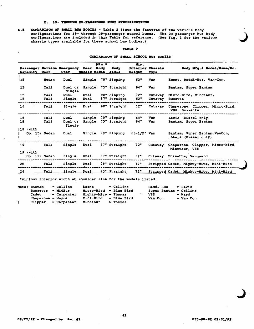
c.s COM»~SOH OF SMaLL 808 80DI&S - Table 2 lists the features of the various body configurations for 15- through 20-passanger school buses. The 24-passenqer bus body configurations are included in this Tabla for reference. (Sea Fig. 1 for the various chassis types available for these school bus bodies.)
»••••apr Capacity
c~liRI&OR or sHJU.L scaooL· BUs Boons
Mia.* ••n-i.oe ... zopaoy Jt-ar 8ody Door Door Wb .. la Wi.cltb
Body
•!.•• 1111>.
Xat•zoior Cba••i• a.!.qht !"vp!
I 115 Saclan Dual Single 70" Sloping 62" Van Econo, Red.di -Bus, Van-Con,
15
15 15
16
18 18
Tall
Tall Tall
Tall
Tall Tall
Dual or Single
Dual Sin9l•
Sing.la
Dual Dual or Sin9le
Single 75" Strai9ht
Dual 90" Slopin9 Dual 87" Straight
Dual 90" Straight
Single 70" S!opin9 Single 75" Straight
64"
72" 62"
72"
64" 64"
Van Bantam, Super Bantam
Cutaway Micro-Bird, Hinotaur, Cutaway Susette
Cutaway Chaperone, Clipper, Micro-Bird, VSS, Bussetta
Van Lewis (Diesel only) Van Bantam, Super Bantam
118 (with I I
Op. 15) Sedan Dual Sin9le
19 Tall Sin9le Dual
19 (wit:h
70" Sloping
87" Straight
63-1/2" Van Bantam, Super Bantam,VanCon,
72"
Lewis (Diesel only)
Cutaway Chaperone, Clipper, Micro-bird, Minotaur, VSS
Op. 11) Sedan Single Dual 87" Straight 62" Cutaway Bussette, Vanguard
-----------------------------------------------------------------------------------------------------20 Tall Single Dual 78" Straight 72" Stripped Cadet, Mighty-Mite, Mini-Bird \
------------------------------~----------------------------------------------------------------------~ 24 Tall Single Dual 90" Straight 72" Stripped Cadet. Mighty-Mite. Mini-Bird
•minimum interior width at shoulder line for the models listed.
Note: Bantam Collins Econo Collins Raddi-Bus Lewis Bussette - Mid.Bus Micro-Bird - Blue Bird Super Bantam - Collins Cadet carpenter Mighty-Mite - Thomas vss - Ward Chaperone - Wayne Mini-Bird - Blue Bird Van Con Van Con
I Clipper Carpenter Minotaur Thomas
03/25/P2 - CbaDged by Aa. 11 070-.. -P2 01/01/P2

D. CIIU8Ia lll'IIC%FI~OII8
c,D.1. GIIDIKIIAL -~·-1.1. OIRKRAL SP.~C~ri~OMS - Tbe requirements for qroaa vehicle weight ratings, gross axle
weight ratings (front and rear) and tire sizes and load ranges, as apecified in Table Nos. 3 through 7 for each size chassis are ~tau. requirements t••• Par. A.4.S.). 'l'be nquirementa are for school buses with standard equipment. S'be aclcMcl ,..~ilt• of opU-.al ...U.-" .- •• al~a,.....u ... ~a•1 ~~t:o ... p ~....,.., ur o.....U~i...W.g, 1"9989& zaaka, llfta toz U. pbyai.oal~y .i.apai~, ozo ot.bezo be~ •~••ori.•• ,..zoe Dot ..-i.S.J:ed ill allt:abli•ll.iag t:ba -oi~:r '&'at.il>g• ~o 1>a -l:tifiad ~or ~- oba••b. If additional optional aqui~nt ia ordered which necessitates increased capacity ratings of either axles, springs or tires, it is the responsibility of the vendor to furnish them so that proper certification can be made on the vabic1e.
1.2. COLOR- The chassis shall be painted black (Color 17038); cowl, fenders, and hood shall be painted achool bua yellow (Color 13432): and bumpers and wheels shall be painted the chaaaia .. nufacturer's .standard color.
D.Z. AZL&8, IJ08ftii8ICII, .JIIID ~ COIIPCIIE!ft'S -
2.1. AXLE CAPACX~K8 - Axle capacities and gross axle weight ratings CGAWRs} ahall ~ as specified in Table Nos. 3 through 7 for each make of vehicle. Increased axle capacities shall be furnished to accommodate optional equipment auch as diesel engines or other heavy accessories as required (see paragraphs A.4.S., 0.1.1., and G.l.7.2.}.
2 .z, aNltliS .JIIID D:r.aBD C ............ ¥8 -
2.2.1. Service Brakes- Service brakes shall be manufacturer's standard hydraulic front power disc brakes and r.ar disc or drum br&kes meeting FMVSS No. 105 as applicable to school buses.
2.2.2. Marning, Low Fluid - Hydraulic aasiat-boosters shall audibly and visually warn of fluid or power loss.
2.3. BUaODOMZTZRS - Each chassis shall be equipped with one hubodometer with standard mounting bracket which shall be calibrated in miles and installed by the manufacturer. The preferred mounting location is on the right rear axle drive wheel. The hubodometer shall be on• of the following:
2.3.1. 2.3.2. 2.3.3,
Accu-Trak, Standard Car Truck, Park Ridge, IL 60068. Engler Instruments, 250 Culver Ave., ~eraey City, N~ 07305. Veedar-Root, Hartford, CT 06102.
2.4. SHOCK AaSORaZRS - Two front and two rear heavy-duty, double-acting shock absorbers shall be installed.
2.5. •~aaa - The ground ratings for the front and rear apringa shall be as specified in Table Nos. 3 through 7 for each make of vehicle (••• paragraphs A.4.5., 0.1.1., and G.l.7.2,),
Z.f. 'l'ID8 .JIIID IID&LI -
2.6.1. Tirea - ~1 standard tires shall be the steel belted radial tubelesa type. ~1 tires aball be new and the tread atyle furnished shall be the tire aanufacturar'a standard design and the brand normally furnished on regular productioD order a 11Dl-s O'theEWi•• _,.aJ.fied iD 't.be I.a..-J.tatioa for 8iCS.. All tires ab&ll be •original Equipment Line Quality.• For tire size and load range for each size cbaeaia, see Table Nos. 3 through 7 and the MaJOR CCMG>Oh&M'S CDJa' •
2.6.2. Wheel, Spare - WbeD •o ~cLfi•d iD 't.b• l.DYitation for •id. <••• Option No. 31), tbe bua ahall have a apare wheel; b~r carrier &Dd tire/tabe for ... zoe •bee1 rill lle't be prOOYi.clad ~r 't.IU.• option.
D.3. CIIA.I8I8 I'IIAia .JIIID DJ.U'KD COIIPOIIIilft'l -
3.1. BtiMPDS, ftOlft' ARD aDa - Front and rear bum.pera ahall be chassis manufacturer's standard except the rear bumper furnished by body manufacturer shall be of the size and type and attached to frame as deacribed in Par. C.l.2.
070-IB-•z 01/01/,2

D. 15- iriiX>ll!ill 20- I'UIIDIG&a CJIAIIIa II'ECIJ"ICM'IORI
3.2. CBASSII rRAMK SID& MZMpzas - Each frame •ide member shall be of one-piece construction. If the frame aide members are extended, auch extension shall be designed, furniahed, and guaranteed by the installing manufacturer. The installation shall be made by either the chassis or body manufacturer. Extensions of frame lengths are pe~issible only when such alterations are welded on behind the hanger of the rear spring. This apecification does not perMit wheelbase extensions. Any welding, beating (for frame straightening or repairs), or the drilling of holes in chassis frame members ahall be in accordance with chassis manufacturer'• recommendations.
3.3~ J"au. r.&latl, COifVD!'XORA.L J'UEL - Standard and auxiliary fuel tanks ahall ... t P'HV'SS No. 301 as app~icable to achool buaas and ahall .. et the current design objectives of the SBHI. Fu.l tanka ~natalled on rexaa achool buaea ahall have a minimum "draw" of 83t of capacity.
3.3.1. Fuel ~anks, Standard - The atandard fuel tank ahall have a minimum capacity of 21 gallons. The tank shall be mounted, filled, and vented entirely outside the body (see Par. D.5.4.3.)
3.3.2. Fuel rank (s), Auxiliary - WbeD •o •peoi.~.ied i.D 't.IMI %Jn'i.~a~J.OD. ~or BicS., (see Option No. 12), the bus shall be furniahad with a minimum capacity 30-gallon fuel tank or tanka furnished and installed by the chaaaia manufacturer.
3.•. ro&L ~(8), AL~ FOZL- Fuel tank(s) for alternative fuels (see Option 3) shall meet or exceed all of the rules and regulations of the rexas Railroad Commission. Capacity shall be that required to meet the range requirements as specified in Option 3 (also see Par. 0.5.3.3.) or as _,-cifJ.ed J.D ~be IDYi.~atJ.OD. ror Bid8.
3.5. 8%Z&Rl.C, POWER- The bus shall be furnished with the chassis manufacturer's standard power steering which will provide safe and accurate performance at maximum load and speed.
D. « . J:LI:C'rlll:CAL 8YI!'DC AND RI:U.ftD COIII'OIIJ:RTS -
•.1. AL~RRArORS - The 12-volt alternators with rectifier shall have the electrical outputs and the minimum charging rates shown below when tasted in accordance with SAE rating at the manufacturer's recommended engine speed. These alternators shall be ventilated and voltage controlled and, if necessary, current controlled. ~ternators
shall be provided as follows:
4.1.1. ~ternator, Standard - Type A buses and Type B buaes shall a standard alternator with a minimum electrical output of 75 amperes with qa~oline or alternative fuel engines (65 amperes with diesel) and 100 amperes, respectively.
4.1.2. ~ternators, other- School buse• equipped with the following equipment •ball baTe alternators as follows:
4.1.2.1. Air-conditioned Buses - Type A buses and rype B buses equipped with air conditioning shall have alternators with a minimum electrical output of 100 and 130 amperes, respectively.
4.1.2.2. Wheelchair Lift-equipped Buses - Type A buses and Type B buses equippe-d with wheelchair lifts shall have alternators with a minimum electrical output of 100 and 130 ampere•, respectively.
4.1.2.3. Air-conditioned and Wheelchair-equipped buses - Type A buses and Type B buaea equipped with both air conditioning and wheelchair lifts shall have alternators with a minimum electrical output of 130 amperes and 160 amperes, respectively.
4.1.3. ~ternator, Optional - Wb.a •o ~oJ.~~ed ~D ~be IDYJ.~at~on ~or Bid• (see Option No. 4), Type A buses ahall have an alternator with a minimum electrical output of 100 amperes and Type B and c buses shall have an alternator with a minimum electrical output of 130 amperes, respectively.
070-IB'-82 01/01/82
J

4.2. ~ ARD ~D ~· - ~he storage battery furnished on each chassis shall have aufficient capacity to aupply current for adequate operation of the engine starter, lighta, signals, heater, and all other electrical equipment. The batteries fo"r 15- through 20-pasaenger achool buses shall have a potential of 12 volts and meet the following:
4.2.1. Battery, Diesel Engines - The batteries furniabed with diesel engines shall be aa apecified by tbe chassis manufacturer. When two batteries are provided, they ahall both be inatalled under the hood or one shall be inatalled under the hood and the other ahall be installed in a battery box having outsiO. access. Single batteriea aball be installed under the hood.
4.2.2. Battery, Gasoline Engines - 'l'he minimum perfomang• level shall be a BCI cold cranking capacity of no leaa than 360 amperes @ 0 r with a minimum lOO~nute reserve capacity.
4.2.3. Battery(a), ~ternative fueled vehicles- Dedicated alternative fueled vehicles shall have batteries meeting or exceeding thoae required for a gaaoline engine school bus with comparable horaepower. Batteries for dual fueled buaea ahall have batteries apecified by the conventional fuel used.
4.3. aORRS - Each bua shall be equipped with horn or horns of standard make. Each horn aball be capable of producing audible aounda in the frequency range from 250 to 2,000 Hz and at an intensity of between 82 and 102 decibels. The sound level measurements shall be made at a distance of 50 feet directly in front of the vehicle in accordance
·with SAE J377.
4.4. IRIDtJNilft"S ARD DSikONIINi I'AII&L - The bus shall be equipped with the following nonglare illuminated instruments (controlled by an independent rheostat•) and gauges mounted for easy maintenance and repairs and clearly visible to the seated driver. Indicator warning lights in lieu of gauges are permissible as shown below:
4.4.1. 4.4.2. 4.4.3. 4. 4. 4. 4.4.5. 4.4.6. 4.4.7. 4.4.8.
Ammeter (or Voltmeter) with graduated charge and discharge indications Fuel Gauge Glow Plug Indicator Light (for diesel buses with glow plugs only) Odometer (6 digits, e.g., register to 99,999.9 miles) Oil Pressure Gauge and/or Harning Light Speedometer Vehicle manufacturer's standard ~eyed Ignition Switch Water Temperature Gauge and/or Warning Light.
•ROTE: If the intensity of the body-installed panel lamps is controlled, then the intensity control shall not be accomplished by the same rheostat that controls the chassis instrument lamps, unless the body company designs and installs the rheostat to accomplish both.
4.5. LMIPS - Each bus shal.l be equipped with at least two clear heac:Uamps meeting the requirements of FMVSS No. 108 and a dimmer switch located at the far left of ateering column. Adequate parking lamps operated by a switch in common with the headlamps shall be provided.
'·'· t'IIIIR-8IOR&L A1ID VliBictllM- llaRIIL OPDA'tliiQ ORI'l'l AftD FLUBI:IIS - ~be operating units and flashers for turn-signals and vehicular hazard warning signal• shall meet the requirements of FMVSS No. 108 (see .paragraphs C.1.7. and C.l.ll.).
4.1 ~MQ - The chassis •anufacturer shall provide a readily accessible terminal strip or plug on the body aide of the cowl, or at an acoesaible location within the engine compartment, with the following minimum terminal• for the body connections:
4.7.1. 4.7.2. 4.7.3. 4.7.4. 4.7.5. 4.7.6.
Backup lamps Instrument panel lights (rheostat controlled by head lamp switch) Left turn signals Right turn signals Stop lamps ~ail lamps
070-11-82 01/01/82

D.!i. IIIIQJ:IIIi .IKD ULADD CDIIPOIIKRU -
5.1. AXR CL&ARER - zach chassis aball be equipped with a taotory-inatal~ed maximum capacity, replaceable dry element type air cleaner.
5.2. COOLXRG a%8TZM- The cooling system ahall have the manufacturer' a largest heavy-duty radiator available for the aeries and shall be of aufficient capacity to cool the engine at all apeeda in all gears. The cooling ayatam fan shall be the heavy-duty reinforced type.
5.3. KRGrRZS - Approved engines listed in each table for the various size buses are the anginas for which the vendor baa requested approval and are .. aally the amallaat engine in terms of performanc.-tbat will .eat the requirements listed below. Other approved engines which the vendor may provide with a given chassis will be listed also in an Approved Products List (APL) • The APL will be updated aa new engines or additional veraiona of curr•nt anginas are approv•d. »a-a•• aot• ~ba~ ~y ~bo•• •D9LDe• apprvN~d •• qeaifiecl below aDd l.iatecl eitbezo b i:.he !'.a.aa lcllool Baa lpeoifioatJ.oa or b ~ C~••• 070-18-APL will be aooeptabl• for aabool bu•••.
5.3.1. Dioael Engines - lll:.eD •o .,.o.J..fied J.D t:.be lD"'"'i~ati.oa for 8ida (aee Option No. 8), the 15-, 16-, 18-, 19-, or 20-passonger school bus chassis shall be furnished with a 4-cyclo diesel angina.
5.3.2. Gasoline Engines - Engines for the 15- through 20-paaaenger buses ahall be of the gasoline type GAl••• otberwi•• ~cJ..Eiecl iA ~be 1DTJ..ta~ioa Eozo Bid.. Approved •ngin•• are listed in Tables Nos. 3 through 7 &Dd in the Class 070-SB-APL.
5.3.3. Alternative Fuel Engines -JibeD ao ~cified J..n ~- lDTi~at.ioD for Bid. (See Option No. 3), the 15- through 20 passenger buses shall be equipped with engines operable on alternative fuels.
5.3.4. Power Requirements - Each bus shall be furnished with an engine that meets or exc•eds the following aiDiaua criteria (ae• second note at tho end of Par. 0.5.3.5.8.), when tested at or above the GVWR required for a given bus capacity and with all accessories except air conditioning compressor on and operating:
5.3.4.1. 5.3.4.2. 5.3.4.3. 5.3.4.4. 5.3.4.5.
Acceleration from 0 to 50 mph in 60 aeconda or leas. Gradeability of 1.5, minimum at 50 mph. Gradeability of s.o, minimum at 25 mph. Startability of 20' minimum. Top speed of 55 mph minimum at the manufacturer's rated rpm for the governed engine.
5.3.5. Approval of New Engines - Procedur•s for approving new achool bus anginas for 15- through 20-passanger school buses shal~ ba as fo~~owa:
5.3.5.1. Submit to the Specification Section, a letter certifying that the proposed engine meets or exceeds each requirement of Par. 0.5.3.3. when inata~l•d in the largest size bus for which approval is requested.
5.3.5.2. The Specification Section will review tba request and advise the vendor or manufacturer by ~.t~ezo that their request for engine approval and their statement on engine performance have been received. Copies will be furnished to the School Bus Committee.
5.3.5.3. If this review verifies that the engine meets the requirements of this apecification, and is so stated in the above letter, the vendor or manufacturer shall contact tho GSC Purchaser to arrange for testing of the engine in the largest size school bus for which approval is requested. The Purchaser will consult with the TEA Representative and inform the vendor of the name(a) of the school diatrict(s) from which to select a participating school district.
5.3.5.4. The vendor must obtain the cooperation of one of the named school districts in agreeing to test the bus and to provide a report to the GSC Specification Section on the form provided. (See copy of the Form entitled, "Three Month Teat of New School Bus Engines," on Page 117.)
070-8B-f2 01/01/f2
J

Sa3a5a5a Tbe vendor or aanufacturer aball then contact the GSC Purchaser and T&A School Bus Committee ~preaentative about ordering the school bua with the aubject enqine.
5.3.5.6. The bus shall be tested for a period of not less than three months during the regular nine-months school term, preferably on a variety of routea and on activity tripa.
5.3.5.7. Opon receipt of the achool diatrict'a ~•port, the Specification Section will •aka a recommendation at the next meeting of the School aaa Committ .. that the enqine be accepted or rejected.
S.3.5a8. The School Sua Committee will act on this recommendation and, if approved, the engine will be added to the Class 070-SB APL.
~1: Onoe an engine 1• approved in one horaepower and torque veraion, other power veraiona of thia aame engine need not be tested in a achool bus prior to approval. For approval, the vendor or manufacturer shall follow Par. D.S.3.5.1., and, in addition, atate the rear· axle ratio recommended for the aize bua for which approval ia requested. Then the engine will be added to the Class 070-SB-APL which will ahow the gross horsepower and torque as well as the rear axle ratio for the particular application.
!'a VALOIII or Dial>~, BORSII:POIIJ:II, .aRD '1'01\Qtlll: LU'l'II:D l:R !'a rOLLORIRQ 'rULIS tJRDD II:ACII IIIUft!I'AC'l't!RZII AD R0'1' llll:RDIOII VALOIII .aRD IBOCLD RO'r U COI'ISTIIUII:D .U lt!CII. !'D ORLY IIIRIMOII IRI:Qtll:IIDIII:II'l'S roll !'811: l>DFOIIMIINCII: or IIRIOXRII:S D1 15- !'IIIIOtlQB 20-l>.USII:HQD ICBOOL BtJIII:S D1 !'811: &!'Aft or !'UAS AD !'a riVII: RIQIIXIIDIII:II'l'l Ll:S!'II:D l:R PAR. D.5.3... (There are additioaal requirements tor engines, either implied or specified, separate from the above performance requirement a • }
5... KX&AtJS!' SYS!'II:H -
5.4.1. Component Placement - The exhaust pipe, muffler, and tailpipe shall be mounted under the bus and attached to the chassis frame.
5.4.2. Noiee Level - The noise level ahall neither exceed EPA "Noise Emission Standard5" nor 85 dB(A) at the ear of the occupant in the bus nearest the noise source.
5.4.3. Tailpipe Exit - The tailpipe of a gasoline-powered bus shall not exit the aide of the bua anywhere within 12 inches. of a vertical plane through the center of the fuel filler opening and perpendicular to the side of the bus, unl••• protected with a metal shield to divert spilled fuel away from tailpipe.
5.5. OIL riL~ - Each cbasaia ahall be equipped with a factory-installed, minimum one-quart capacity oil filter with a replaceable filter element.
!I.C. 'fJICIIOQJUU>B - - •o ~tied ill t.,. I""itati0111 fol< tida <••• Option No. 27), a tachograph containing a coabination clock/speedometer/recorder shall be installed on the dashboard. The taohograph shall be Argo Model(s) 1310-6, Vee~r-Root Model 1407, or approved equal.
D. C. 'l'IWtiiiiS8IOR JUG) DW.'l'II:D CCWOKCidl -
1.1. A~C ~S~SSIOR, a~ARD - The standard automatic transmission shall be the 3-or 4-forward speed automatic type, and shall be one ef the following:
6.1.1. -Chrysler Motor Corporation's "A727 LoadFlite," 6.1.2a -Ford Motor Company's RSelectShift" or, 6.1.3. -General Motors Corporation's "Turbo Hydramatic."
Ca2a Darv& S&Arf Q~ - Each drive shaft section shall be equipped with protective metal guard or guarda to prevent the shaft from whipping through the floor or dropping to the ground when broken.
<17 070-a8.-t2 01/01/U

D. 15- DIROIJQB 20- • .UI&RQBJI CJIUII8 DZCD"ICM'IORI
J J"IQl!R& 1
--
•• 07o-aa-ez 01/01/ez

'r.ULil 3
' 1!1•P.U8D""R 808 CBAlla%8
lBU: PAR. 8 .1. 2. 010 UDOCI:D P.UftiOQI:P. CAPAC%'1'lC) Ref
!'AIILI: 4 15-PASSENQER aos CHASSIS
(ID PAl\. a.l. 2. OM JR&DOCI:D PASSII:RQD CAPACI!'lC.)
lf-»•••erapr ·I'l'II:M
GVWR, lbs
GAMR, lbs - Front - Rear
Axle Capacity, lbs - Front - Rear
Wheelbase, in Chassis Length, in
Track, in - Front - Rear
Gasoline Engine CID SAE Gross Horsepower SAE Gross Torque, lb-ft
Transmission, Auto
Tires, Steel Belt Radial Size ' Load Range
Wheels, Rear
1PP2 MiD.
•• 10000
3800 7200
3900 7500
125 as required
69.3 73.2
• • •
A4
Tubelesa
Dual
Alternator. amperes 85 *See minimum power requirements in 0.5.3.4. **Furnished with diesel engine only, Option e.
Refer to CbOOTr<>1•t/GNC:
10131303
10000
3900 7200
3900 7500
125 197.6
69.3 74.0
350-VBEFI 201 318
A400
LT225/ 75Rl60
Dual
85
DJ:II:SII:L II:RGINJ: (Option 8)
General Requirements. Fori .. 350••
10000
3800 7810
4600 7800
138 237.4
70.0 73.2
•• •• ••
E400
LT225/ 75Rl6D
Dual
95
16-Pa•••ng-.r 1992 CbeTrol.•t/QMC Ford I'l'II:M MiD. 10131303 II: 350 .. Engine D,isplacement, L. • 6.2N-VB 7.3N-VB SAE Gross Horsepower • 164 180 SAE Gross Torque, lb-ft • 302 345
Alternator. amperes 100 100 100 *See minimum power requirements in 0.5.3.4.
Page 4
Engine~ li~t•d on this operating conditions. <~·· 0.5.3.4.)
page are approved to meat or exceed power requirements under normal other engines must be submitted for approval by the Schooi Bu~ Committee
The following bodies are available on commercial cutaway chassis in this configuration~
15-PASSII:RGII:R aODIII:S (Miele Body, Straight Side, Style 2 Service Door*)
16-P••••Dg•:r: 1992 .Aa'l'r&D/Ward. Blu• Bi.rd Carpa.D't.•r !'boaa• Wayn• I'l'II:M MiD. VSS15 llioro-Bi.:r:d •cL lli.Dot.aar"""" CbaP-ron•
•• Interior
Headroom, in 72 74 74.0 74 72 72.0
Interior Width in 90 90 90.5 90 90 90.75
•conventional Bus Door - minimum 68" tall and 24" wide, folds or separates in the middle to open. **Not available with a diesel angina except as a wheelchair-equipped bus (14-passangar).
50 070-BB-PZ 01/01/92

"I 'l'AIIL& !I 11-PABSEHQIR 803 CBASSIS
(ftl: PAll. 8 .1. 2. OM IUDOCJ:D PAUI:11013D CAPACITY.)
Refer to General ileauirements. 11-»•••--v-z- 1PP2 Foftl IftH lti.D. II: 3!10
Page 4 CbaY/aMC
I!.Pt•· ~··•v 031303 GVWR, lba
GAWR, l.b.- Front - Rear
Axle Cap. , lbs - Front - Rear
Whaal.baaa, in Cha1u1ia Length, in
Engine, CIO SAE Gross BP SAE Groaa Torque, ~b-tt
Transmission, Auto
Tires,Steal Belted Radial Size ' Load Range
fthaela, bar
9200
3900 5360
HOO 6000
138
• • •
A4
Tubeless as shown
Single
Alternator. amoeres 100 *See minimum power requirements in 0.5.3.4. **Furnished with diesel angina only, Option B.
DII:SI:L II:RQIRE (Option 8)
16-»••-nrr 1PP2 Cta.rrol•t/GJH: ITIUI KiD. 031303
•• Engine Displacement, L. • 6.2N-V8 SAE Gross Horsepower • 164 SAE Gross Torque, lb-f't • 302
Alternator. amptras 100 100 *See minimum power requirements in 0.5.3.4.
9600
3900 6084
4600 7800
138
•• •• ••
1:400
LT245/ 75Rl6E
Single
100
Ford II: 3!10
7.3N-V8 180 345
100
9200
4100 5360
4700 6000
146
350-V8EFI 201 318
A40D
LT225/ 75R16E
Single
100
Engines listed on this page are approved to meet or exceed power requirements under normal operating conditions. Other engines must be aubmitted for approval by the School Bus Committee (see D.5.3.4.)
The following bodies are available on van conversion chassis:
18-~ASSII:110131:k 808 BODIES (Witb Dual (or Single) Rear Emergency Door)
11-Pa•••DSI'!r 1PP2 Co~~LD• Lew.te Van Con
Interior Beigbt 63 64 65 63.0
Interior Width 75 75 75 72.0
Entrance Door Height* 53 53/74 70 65.0
Paaaenqer Seats (26"-39" Benches):
Left Side, rows 4 or 5 4 or 5 5 5 Curb Side, rows 4 or 5 4 or 5 4 5 ltnee Space, in 24 24 26 26 Aisle Width. in 13 13 15 15
*Option 11 allows automotive type (Style 1) aervice doors.
51 03/25/P2 - Cb•=gecl ~ .a.. 11 (OaaolJ.De obaaai.a aclckd.. ft.•rcU.V&Il x-.. o..-.d) 070-SB-D2 Ol/Ol/D2

DJILit ' 1P-PAS8KRQZR 808 CBASSIS
(UJ: PAP.. 8.1.2. OR RJ:Dt!CJ:D P.UaUCU. CAPACI'l'X.)
GANR, lba - Front - Rear
Axle Capacity, lbs - Front - Rear
Wheelbase, in Chasaia Length, in
3900 7200
3900 7500
125 as required
3900 7200
3900 7500
125 197.6
3900 7810
4600 7800
138 232.4
----------------------------~------------------------------------------Track, in - Front - Rear
Gaao~ine Engine CIO SAE Gross Horsepower SAE Gross Torque, lb-ft
Transmission, Auto
69.3 73.2
• • •
A4
69.3 74.0
350-V8EFI 201 318
A400
Tires, Steel Belted Radial Size ' Load Range
Tubeless as shown
LT225/ 75RI60
Wheels, Rear
Alternator. amperes *See minimum power requirements ~•Furnished with diesel engine
Dual Dual
85 85 in 0.5.3.4. only, Option 8.
70.0 73.2
•• •• ••
E400
LT225/ 75RI60
Dual
130
DIJ:SJ:L J:ftCrRJ: (Option 8)
lP-Pa••eDgr-r 1PP2 Cb~rol•t/QW;; Ford ITJ:N His>. C31303 1:350
•• Engine Displacement, L. • 6.2N-V8 7.3N
SAE Gross Horsepower • 164 180 SAE Gross Torque, lb-ft • 302 345
Alternator. amperes 100 100 100 *See minimum power requirements in 0.5.3.4.
Engines listed on this page are approved to meet or exceed power requirement• under normal operating conditions. other engines muet be aubmitted for approval by the School Bus Committee (see 0.5.3.4.).
The following bodies are available on commercial cutaway cba•sis in this configuration:
lP-Pa••enpr 1PP2 ITDI lti.D.
!'!P!:•.
Interior headroom, in 63
Interior width, in 84
Service door as shown
AaTraa/Ward a~a- BLrd Carpan~•r rbo.a• ~dBu• V&DgUard•/ ~aro-81rd 8CL ~~aar 8u••~~·
V881P Cllpp!r
74 74 74 72 63
90
sedan*/ tall
90.5
tall
90 90 84.72
tall tall
*Available only with Option 11, Sedan-type Service Door.
52
72
90.75
tall
070-a8-P2 01/01/PZ

DaLE 7 20-PA88ZRQ&R •os CBASSIS
(ft& PAP. ••• 1.2. 011 R&Dt!aD PAaSJ:RQU C:UACrrY.)
GVWP., lbs
GAKR, lbs - Front - bar
Axle Capac~ty, lba - Front
Wheelbase, in Chassis Length, in
Track, in - Front -bar
Gasoline Engine CID
- bar
SAE Gross Horsepower SAE Gross Torque, lb-ft
Transmission, Auto
Tires, Steel Belted Radial Size ' Load Range
Wheels, Rear
KiD.
•• 11500
4400 7900
5000 7900
125 aa required
65.2 66.7
• • •
A40D
Tubeless as shown
Dual
~ternator. ampere• 105 *See min~ua power requirements in 0.5.3.4.
Engine Displacement, L. SAE Gross Horsepower SAE Gross Torque, lb-ft
AJternator. Amperes
DIKSI:L ZRQilU COption 8)
1U2 KiD.
h.
•• •• •• 100
**See minimum power requirements in 0.5.3,4,
6.2N-V8 164 302
100
P30U2
11500
4400 7900
5000 7900
125 214.8
65.2 66.7
350-V8EFI 201 318
A40D
8R19.515
Dual
lOS
Engines listed on this page are approved to meet or exceed power requirements under normal operating conditions. Other engines must be submitted for approval by the School Bus Committee (see D.5.3.4.)
~be following bodies are avai~ab~• on atripped cbaaaia:
20-PASSI:RQI:R •oa .ODII:S (Straight Side, Style 2·service Door*)
20-P•••~r 1tt2 ~~ KiD • ......
Interior Headroom, in 73
Interior Width, in 78
Bl.u• Bi.rd. lliDi-Bil«<
90.5
Ca~nt.•r Caclat
90
73
78
Service poor aa •hown Tall Ta.ll Tall *Conventional tba micld.le to
bus door - minimum 68" ta~l and 24" wide, folds or separates in open.
!13 070-.. -S2 Ol/Ol/S2

••
1.1. 80DY »BYSICAL RK~S - Physical requirements for the 24- through 83-passenger achool buses shall conform to the following table <••• Option No. 15 and Par. A.1.3.}:
(1) (2) OV&Jia.Llo
KIRI- aoDY IIJ:II IIIDD
"'-b.r 0~ ucm.., »•••eaera Mezi aa
24 96 35 102 47 102 53 102 59 102 65 102 71-S 102 71-L 102 77 102 83 102
ROT&S: Column (4)
Column (5) Column (6)
!l'ULI: RD. I
(3) -· or
(4) (5) laM'
IIIDD L&l'~ IUQII~
(6) C&ftf&R
(7) rLOOa-ro
CIIILmo IIIIIQft IIUft
&aah Minieua bob••, Mini ua
bab.e, ICi.U..U.
5 6 e 9
24 25 25 25 25 25
39* 26 39* 39 39* 39 39* 39
12 12 12 12 12 12 12 12 12 12
72 72 72 72 72 72 72 72 72 72
10 11 12 12 13 14
24-3/4 25 25
24-3/4
39* 39 39* 39 39* 39 39* 39 39* 39 39* 39
~•• apace is defined as the horizontal distance from the front center of a seat back to the rear center of the seat back or barrier immediately ahead, measured at approximately 4 inches above the seat cushion. Knee space may be reduced to 24-3/8 inches, only on those 83-passenger bus seats where it is impossible to achieve 24-3/4 inch space. *Left rear seat shall have minimum width o~ 26 inches. Floor-to-ceiling height shall be measured in the center of the body between the No. 2 pillar and the laat aide body pillar ahead of the rear roof slope.
1.1.1. Overall Length - The overall length of a complete school bus shall not exceed 40 feet.
1.2. BUMPER, REAR - The rear bumper shall be furnished by the body manufacturer. It shall be secured to rear chassis frame and it shall be designed so as to prevent "hitching of rides• by obtaining a toehold thereon. The bumper shall not be permanently attached to the bus body, but shall wrap around the body, extending forward for at least 12 inches on each aide. The bumper ahall be of preased ateel channel at least 3/16-inch thick by 8 inches high. It must be bolted to the cbasaia frame and braced with material of at least equal impact ratio as the material in the bumper.
1.3. CZILXRQ - The ceiling shall be free of all projections likely to cause injury to passengers. (See Table above for ceiling height requirements and Par. E.2.9. for other ceiling requirements.)
1.C. COLORS aDd LK~RQ- A first quality black enamel (Color.No. 17038 of Federal Standard No. 595a) or decal• shall be used for lettering and trim. The properties of the black enamel shall be equal to those of the finish coat enamel. Pressure-aensitive tape or decals are acceptable for tr~ or lettering (e.g., KMKRQ&RCY DOOR, ~ ZXX~, etc. signs), provided they are made from FAISON R 200, 3M Series 180, or approved equal material.
1.4.1. Body Zxterior - The exterior of the complete bus except for bumpers, rub raila, and wheels ahall be finished in school bua yellow {Color No. 13432 of Federal Standard No. 595a). The hood may be coated with non-reflective school bus yellow paint. WbeD •o ·~c~~~•d ~D tb• IDT~tat~oD ~or B1da (see Option No. 38), the school bus roof shall be painted white. The paint on the roof shall extend from the back of the front cap to the front of the rear cap and from a point on each aide of the bus which is no lower than the top of the windows and no higher than the atart of the roof curvature. The paint ahall be the aam• quality •• the paint on th• r•mainder of the school bus.
070-11-12 01/01/12

1.5.
1.4.2. Body Interior - ODl••• otberwie• .,.olfied iD tbe !DYitatioD for Bide, the interior of the complete bus body shall be finished in the manufacturer's standard color .aaept where clear-coat galvanized steel i• required (see Par. !:.2.9.) 0
1.4.3. Chasai·s components - VDl••• ot.Mrwi•• apeaJ.fi•d .t..D t:lw :larritati.on for 81CS., chassis components such as qrillea, frame rails, and wheel covers shall be painted the chassis manufacturer's standard color.
1.4.4. Emergency Door Lettering - The rear emergency door exit shall be marked ·~ DOOaw or ·~ ZXX~,w both on the outside and on the inside with at least two-inch high lettering placed on top of, .or directly above the azit.
1.4.5. Exterior Mirror Backs and Brackets - The metal backs of all exterior mirrors, ~~ ~ed, and all exterior mirror brackets shall be finished in lusterless black (Color No. 37038. aee paragraphs £.3.8.2. and E. 3.8.4. for optional stainless st .. l mirror backs and brackets) •
1.4. 6. Logos - Bo 1ogo1 t~.._.rlt., LD•i.gDJ.a, or 1et:-t.ere eba11 be p1aa.d OD ~r• or .ad ~1aps. A small ••tal or plastic plate designating body manufacturer's name aay be attached to the bus body. A logo of reasonable size, which has been approved by the Specification Section, may be placed on the exterior bus body.
1.4.7. Rub Raila- All rub rails, except the pressed-in type window level rub rails, shall be painted black (Color No. 17038). The pressed-in type rub rails shall be painted either black (Color No. 17038) or school bus yellow (Color No. 13432) at the option of the manufacturar.
1.4.8. School Bus Lettering - The school bus bodies shall have the words wacaOOL 80S" in neat, clearly defined block letters on the front, rear, and on both sides of the bus body with black paint (Color No. 17038 of Federal Standard No. 595a). The letters shall be 8 inches high and shall have l-inch vide strokes. The vorda RSCBOOL 80S" aball be at the aame leval on each aide of the bus (i.e., same height above bottom of skirt).
1.4.9. School Name Lettering·- When •o .,.cd.fiecl iD tbe !ln"J.tati.OD for BiCS. c ... Opt~oA 20), the school district name ahall be provided in black letter• on both aides of the bus near the belt line. Lettering shall be minimum 5 inches high with minimum 5/8-inch block strokes. Paint, if used •hall be equal in quality to that of the bus body paint; decals shall .-at or exceed the raquiramants in Par. E.1.4. Jl-.xiaua na.ber of abaraat.ere iA ODe 1iDe of t.be aaae i• 1iaJ.ted to tbe bua laaqtb. The school district should list in the space provided on the School Bus Requisition Form (see sample form on page 19), tha name to be placad on the bus. Characters ahould be typed or printed plainly on this form to ensure accurate spelling.
1.4.10. Wheels - The wheals ahall be painted the chassis manufacturer's standard color.
:ntSULATIOR, ROlU: -measured at tba ear exceed 85 dBA, when Procedure of NSSB.
Each school bus shall be constructed ao that the noise level ot the occupant neareat the primary vehicle noiae aource ahall not tested in accordance with the procedure given in the Noise Test csee Option 24 for reduced interior noise level package.)
l.C. IR~rtOR, ~..aL - The ceilings and sidewalls shall be thermally insulated with a fire-resistant material approved by Underwriters Laporatories Inc. to adequately reduce the noiae laval and to minimize vibrations. Buses shall have tba equivalent of 1-l/2 inches of Fibarglaa or other insulation in the ceilings and walla including the interior of hat-shaped bows. Any insulation used ahall have a minimum R-factor value of 5.77.
1. 7. LAMPS, SICIU.LS, ABD DJUIIRQ DEV%<38 - Each bus shall be furnished with the lamps liated below (see SMBI standard No. 001):
1.7.1. Alternately Flashing Signal Lamps -Each achool bus shall be equipped with eight warning signal lamps, fou~ ~d and four aabe~, working in an automatic non-sequential integrated system. The signal lamps shall conform to the desiqn, installation location and operating requirements of Paragraph 84.1.4. of FMVSS No. 108:
55 070-la-P2 Ol/Ol/P2

"S4.1.4.
••• (b)
Each ecbool bua eball be equipped with a eyatem of
Four red aignal lampe designed to conform to SAE Standard J887, 'School Bua Red Signal Lamps,' July 1964, and four amber signal lamps designed to conform to that standard, except for their color, and except that their candlepower shall be at least 2-1/2 times that specified for red signal lamps. Both red and amber lamps shall be inatalled in accordance with SAE Standard JB87, except that:
(i) Each amber signal lamps shall be located near each red aignal lamp at the aame level, but closer to the vertical centerline of the bus; and
(ii) The ayatem ahall be wired ao that the amber signal lamps are activated only by manual or foot operation, and if activated, are automatically deactivated and the red signal l.mps automatically activated when the bus entrance door is opened. •· ·
ROD: ~ la.p• •ball M wheel h.peD.ntly &Dd Dot wb•d ~b.r0119b ~ba .l.qnit.l.oD .,..!.tab. !"b.l.• w.l.ll allow ,_.,..al o~ ~ba ~~t~oa key w~tboat -~~.at~Dg ~rat~oD o~ ~ alt•rDat•ly ~laehiog •~gbt ••~~D9 •~;Dal 1.-pa.
1.7.1.1. Band- Each set of amber and red lamps shall have a minimum 3-inch black band around the aet and a 3-inch band between the lamps in •ach set. The color of this band shall be black enamel (Color No. 17038, Black Enamel of Federal Standard 595a). If it is not possible to provide a 3-inch band between the lamps in. the set, the manufacturer will then provide a band as wide as possible. Any visor or hood used to shade the lights and improve visibility will not interfere with the intensity and photometric performance of the warning lights (see SMBI Standard No. 001).
1.7.1.2. Mounting- If exterior panels are cut to provide an opening for installation of flush-mounted signal lamps, the lamps must have a closed cell sponge flange gasket with a minimum thickness of 3/16 inch. The gasket shall be the full width of the flange on the lamp. Proper installation of the lamps shall be made in order to prevent •••page of moisture into the opening.
1.7.1.3. Operating Instructions- Complete instructions for the detailed operation of tho warning .. ignal lamp aystem ahall be furnished with each school bus.
1.7.2. Backup Lamps - The color, requirements, and mounting of backup lamps shall be in accordance with FMVSS No. 108, exoept ~ backup la.p• are zoequ.~~.d. by S'aaaa lpeoi~ioat~oa•.
1.7.3. Clearance, Identification and Side Marker Lamps - Each bus shall be furnished with the lamps listed below. The quantities, colors, requirements, and mountings shall be in accordance with FMVSS No. 108. Each identification, clearance, and aide marker lamp inatalled to indicate school bus height and/or width shall be the armored flush mounting type for protection of lens from damage during normal operation. The armored protector• shall in no way interfere with the intended purpose of the lamps. The armored type protectors shall be Grote Manufacturing Company, Hadiaori, Indiana 47250, Hodel Nos. 45012 and 45013, or KD Lamp Company, 1910 Elm Street, Cincinnati, Ohio 45210, Model Nos. 38469-901 and 40268-301, or Meldon Hodel No. 5050, or approved equal. (See SBMI Standard No. 001 and FHVSS No. 108 for the types and proper location of these lamps.)
Example of an approved equal: Paterson Hodel - PM122.
1. 7 .3.1. 1.7.3.2. 1. 7 .3.3.
1.7.3.4.
Clearance Lamps. Identification Lamps. Intermediate Side MArker Lamps Caot ~r.d on bu••• 1••• tbat 30 ~eat loag). Side Marker Lamps.
!51 070-BB-12 01/0l/12

1.7.4. Interior and Stepwell Lampa - Interior lamps ahall be inatalled to properly and adequately illuminate the entire aiale and emergency passageway. The stepwell ahall be illuminated with a aeparate lamp activated by opening the aervice door. The fixtures shall have white or clear plastic lenses attached to aetal receptacles. The atepwell lamp shall also have a metal bezel. The lamps shall be designed for a 12-volt electrical system and shall have installed a ~ .. 15 oaadl-P~r 1.-p bu1b. The fixtures shall be aounted ao as to provide adequate illumination of the pasaenger and driver's compartment. Spacing of the lamp fixtures shall be the option of the bus body aanufacturer.
1.7.4.1. Quantity- The quantity of interior lamps required for each bus aball be as liatecl below:
•caooL ava s:ru (Number of Paasenqers)
24 and 35 47 and 53 59 and 65 71, 77, and 83
:mni\XOR CII:IL%toa LAMPl (Minilllum Required per Bus)
3 4 s 6
1.7.4.2 Stepwell and interior lamps approved are as follows:
Arrow Safety Device Co. Cardinal Mfg. Co. Grote Mfg. Co. K-D Lamp Co. Meldon Inc.
Q£m!. Lamps Stepwell Lamps
043, 036 1271-Gl 230 (61031) 1(1)530-12 8005
(Equivalent lamps with aetal bezels)
1.7.5. License Plate Lamp - The color, requirements, and mounting of the license plate lamp aball be in accordance with FMVSS No. 108.
1.7.6. Reflex Reflectors and Intermediate Reflex Reflectors- The quantities, colors, requirements, and mounting of reflex and intermediate reflex reflectors shall be in accordance with FMVSS No. 108, except one amber reflex reflector on the front, one amber intermadiate reflex reflector on buses 30 feet or longer, and one red reflex reflector on the rear shall be mounted on each side of the bus body. The amber reflex reflectors mounted near the front and on each side of the chassis are required on Texas buses in addition to the reflectors required by FMVSS No. 108.
1.7.7. Tail and Stop Lamps- The quantities, colors, requirements, and mounting of tail and atop lamps shall be in accordance with FMVSS No. 108, except atop lamps aball be 7 inches in diameter and mounted at approximately the belt line level of the bus. A aet of minimum 4-inch tail/stop lamps shall be installed below the 7-inch aet. Base of lamps ahall be metal or durable plastic preferably with screw lens. Lela••• •ba11 a:- -era~ 'to 1aapa by a f'aftenJ.n9 ..tbod wbiab requJ.~• a ~ool ~o ~~ 'tM 1•n•. The lamps shall be Grote 78002 or 78102 tailliqht, !D Lamp Company Models 258-2601 or 258-2605, or approved equal.
1.7.8. Turn-Signal/Hazard Harning Lamps- The quantities, colors, requirements, and aountings of turn-signal/hazard warning lamps ahall be in accordance with FHVSS No. 108, except rear turn-signal lamps aball be 7 inches in diameter. The front turn-aiqnal lamps shall be the double-face pedestal type or they ahall be of tbe •wrap-around typo" ~except ainqle-faeed type on forward control buses) • They shall be mounted in such a manner ao as to be capable of withstanding all normal Vibrations. On double-faced pedestals, the front lens shall be ~~; tbe ~ar lens shall be red or amber, or a shade between red and amber. The operating units and flasher for turn-signals and vehicular hazard warning signals shall aeet tbe requirements of FMVSS No. 108.
!57 070-&B-P2 01/0l/P2

1.7.8.1. Installation - If exterior panel• are cut to provide an opening for insta1lation of flush-~ounted turn-signal laaps, the lamps must have a clo•ed cell sponge flange gasket with a ~um thickness of 3/16 inch. The gasket shall be the full width of the flange on the lamp. Proper installation of the lamp shall be made in order to prevent aeepage of moisture into the opening.
1.7.8.2. Wiring- The exposed wiring to the signal la.ps shall be enclosed in a one-plea. waterproof loom, or equivalent, leadinq directly from the lamp body to the interior of the bus body. The wiring shall be aupported at the lamp body and at intervals of not more than 6 inches until it enter• the bus body.
1. 7. 9. Warning Device• - Each achool bua aball be equipped with three triangular warning devices •eeting the requirements of FMVSS No. 125. The devices shall be packed three per metal or heavy-duty plaatic box, or they may be individually packed in metal or heavy-duty plastic boxes with the three boxes contained within a carrier. Warning devices ahall be .. curely mounted in the driver' a compartment. rziaoplaz waaai.D9 clrrio-a ~ura:l•h-cl aball boa appr~ by 'tbe "-.. o.part. .. srt. of Pub1io 8af•'ty.
1.1. LIC&MSK PLA%Z BOLDER - A recessed license plate holder &hall be mounted on the left rear of the bus body. The recess shall be minimum of 3/8-inch deep at the top and shall be located so that the license plate will receive illumination from the clear ~ens on the underneath aide of the tail light, or by a separate lamp.
1.9. OPENINQS - All openings in the floorboard or firewall between chassis and passenger-carrying compartment, such as for gearshift lever, at .. ring column, and auxiliary brake lever, •h&l1 ~ a•al•d. ~1 openings between cbaasis and passenger-carrying compartment made due to alterations by the body manufacturer abet be •••l•cl.
1.10. PAmnMO -
1.10.1. Preparation and Cleaning-
1.10.1.1. Surface Preparation- The method used in the cleaning and preparation-of all surfaces to be primed shall be equal to that specified by Federal Specification TT-C-490B for equivalent use. The final preparation for priming shall include a careful inspection to make certain that all aurfaces to be primed will permit optimum adhesion of all paint films.
1.10.1.2. Surface Cleaning - ~1 interior and exterior panels and rub rails to be painted or coated shall be thoroughly cleaned to remove all rust, grease, weld slag, and other foreign materia~ prior to priming. Any welds on the components for the bus body or chassis shall be dressed, aanded, buffed, and thoroughly cleaned to remove any slag and to properly prepare the welds for pr~ing. After proper cleaning, these components shall be thoroughly rinsed. Neither the cleaning process nor the rinses shall impair the zinc phosphate coating of the panels or rub rails.
1.10.2. Primer Coat - ~ter the components have been thoroughly elean•d and prepared as described above, they ahall be totally primed and dried. These components may be primed and dried either prior to or after instaLlation. ~1 components such as ~i.-t oE bolt ~ade and daaa9-d area• shall be thoroughly cleaned and primed.
WOftS:
03/25/92 - Cbanv-d by Aa. 11
Co.p~at.• of th• body ~z- •y•t- D-el aot M pz~cl, -..~pt. for ... 1cs.. All procesaes and method• uaed in the priming operation ahall be in accordance with the best recognized industrial practices. Primers shall be those recommended by the paint manufacturer aupplying the finish coat enamala. Primers may be any color.
Clear-coated panel• are required below the passenger windows and in the atepwell (see Par. E.2.9.).
58 070-88-92 01/01/92
J

1.10.3. Finiah Coat - After all interior and exterior panels and rub rails have been prepared, cleaned, and primed as specified above, they ahall be finished with a first quality baking enamel, applied and baked according to the paint manufacturer'• in.tructiona. These enamels, when applied over the paint manufacturer's recommended primer, shall have properties equal to or better than tho•• specified by Federal Specification TT-E-489F, Class B. Both interior and exterior enamel finish coats shall have a minimum dry film thickness of 2 mila, when tested with a "dry film thickness gaugeR (such as the "Elcoaeter Dry Film Tbickneaa Gage," Gardner Laboratory, Inc., Bethesda, Maryland 20014) conforming to Federal Specification TT-C-490B. All processes and methods used in the enamel finish coat operation shall be in accordance with the beat recognized i.ndustri.al practices. %a ao i.D~&Doeo •ball tbe -1 fiAJ.ab ooat M app1i.ed cwezo aa GDpzo~d euzofaoa.
Alternate aethoa. for prepari.ng .. tal surfaces and painting procedures will be considered on an individual basis. Manufacturers shall aubmit their procedural data to the Specification Section of the Commission for approval where aethods are uaed that differ from thoae specified above.
1.11. URD~ - Ondercoating is required to provide for insulation, sound deadening, ·protection froa road minerals, and rust prevention, as applicable, and shall meet the following:
1.11.1. Application - The entire underside of the bus body, including floor members, vheelwells, aide panels below the floor level, and all metal fenders or fenders with metal liners shall be coated with 1/8-inch thick material as specified above. The undercoating shall be applied in accordance with th• undercoating manufacturer's instructions. Do aGt oo.er ap ozo ob1itezoat• tbe oba••1• ~daatifioatioa p1ate (• .. Par. A .•.•. 3.).
1.11.2. Material - Insulating and undercoating materials shall be an asphalt base underbody coating conforming to Federal Specification TT-C-S20B, such as R-477-139, manufactured by Daubert Chemical Co., Chicago, Illinois 60638 or Lion Nokorode Emulsion 331 as manufactured by Lion Oil Company, El Dorado, Arkansas 71730, or an approved equal. An example of an approved equal is Tectyl MC121B, manufactured by ~hland Petroleum Company, Box 391, Ashland, ~ntucky 41101, applied to a dry film thickness greater than 20 mils.
1.12. Wr.RIMG - All wiring shall conform to the current standards of the SAE. All connections shall be made by soldering or by an industry-approved connector. All wires shall be insulated and shall be enclosed in a fibrous loom, or equal, for protection from external damage and short circuits. The vires shall be securely attached to the body and chassis at interval of 24 inches or less.
1.12.1. Accessory Wiring - Body-installed acceaaoriea shall be wired from the battery through a low voltage solenoid cut-off switch operated by the ignition key except for the eight light warnin9 system and hazard warning lights.
1.12.2. Color and Number Coding -A system of color and number coding shall be used and an appropriate identifying diagram shall be provided together with the wiring diagram provided by the chassis manufacturer.
The following body interconnecting circuits shall be color coded as noted:
IONCflOIC
Left bar Directional Signal Right Rear Di.rectional Signal Stopliqhte Backup l.iqhto Tailliqhto Ground Ignition Fe•d, Primary Feed
Yellow Dark Green Red Blue Brown White Black
The color of the cables shall conform to SAE J1128
1.12.3. Fusing - Each circuit, except starting and ignition, shall be fused ••parately or shall have an adequate circuit breaker. Two extra fuses for each size of fuse installed on the bus by the body aanufacturers, shall be conveniently mounted on the bus body.
!18 o~o-.. -82 01/01/82

1.12.4. Main Circuits - The electrical system wiring shall have at least nine main circuits:
(1) Head, tail, stop (brake), and instrument panel lamps. (2) Clearance and stepwell lamps. (J) DoDie lamp a. (4) Starter motor. (5} Ignition and emergency door si;nal. (6) 'l'urn-aignal (directional). (7) Alternately flaahing aignal lampa. (8) Horn. (9) Beater and defroster.
II. 2 • COIII:l'IUJCnON -
2.1. GKRZRAL MZQOZ~S - 24- through 83-pasaenger school buses shall meet or exceed the bus body joint atrengtb requirements o:f FMVSS No. 221. The bodies shall be reasonably dustproof and watertight. The main steel components are listed below and their requirements are listed in Table 9. They shall be constructed of Type 1 steel except as noted there:
2 .1.1. Components ._ The main structural components of the body shall consist of:
2.1.1.1. rbe 8ody r~ ... ly•~ .. - posts, bow frames, strainers, front and rear framing, longitudinal frame members, and emergency door posts.
2.1.1.2. !he &zterior Pane1iDg - side panels, rub rails, service doors, emergency doors, skirts, roof panels, window jambs (post caps),. window sills, and front and rear panels including front cOwl.
2.1.1.3. rbe Floor ly.t .. - floor panels, main cross members, auxiliary cross members, wheelhousing, steps, and stepwell bracing.
2.1.1.4. rbe Xaterio~ Pane1iag - side and ceiling panels.
2.1.2. Body-Chassis Attachment - The body shall be attached to the chassis frame by means of U-bolts with 7/16" diameter threads and a minimum 10,000 lbs tensile pull strength per arm, and the manufacturer's standard clips to prevent slippage between the chassis frame and the bus body. The U-bolts shall be fitted with lock washers and nuts and, after the nuts have been securely tightened, the threads of each U-bolt shall extend a minimum of 1/2 inch past the nuts. Each bus shall be furnished with the following as indicated:
2.1.2.1. Body-Chassis Insulation - Anti-squeak material in continuous strips or rubber pads shall be permanently and firmly attached to the frame rails or croaa members to insulate chaasis from the body.
2.1.2.2. Other Fastening Devices - ~1 other main cross members (not attached by U-bolts) on all sizes of bodies ahall be attached to the chassis with the manufacturer's standard fastening devices where possible. Shear bolts or other equally effective devices approved by the Specification Section of the Commission, may be used in addition to U-bolts and standard clips to eliminate slippage.
2.1.2.3. U-Bolt - Bus bodies shall be attached to the chassis with U-bolts. The number used and their placement shall be as follows:
BtiS SID* 1110. or ti-BOLTI, HiD*
24 1/J an~ 2/J length of bus JS, 47, '53 1 at each end; one in center 59, 65, 71, 77, ' 83
4 (2 on each frame rail) 6 (3 on each frame rail) 8 (4 on each frame rail) 1 at each end; one about one
third and one about two-thirds of length of bus.
*HOTII: School buses equipped with any combination of wheelchair lift positions and conventional seats shall have as a minimum, the number of 0-bolts as if the bus were equipped with a!! conventional seating (e.g., a 71-passenger school bus body equipped with. any combination of wheelchair positions and conventional seats shall have at least 8 U-bolts (four installed on each frame rail).
10 070-88-fZ 01/01/fZ
J
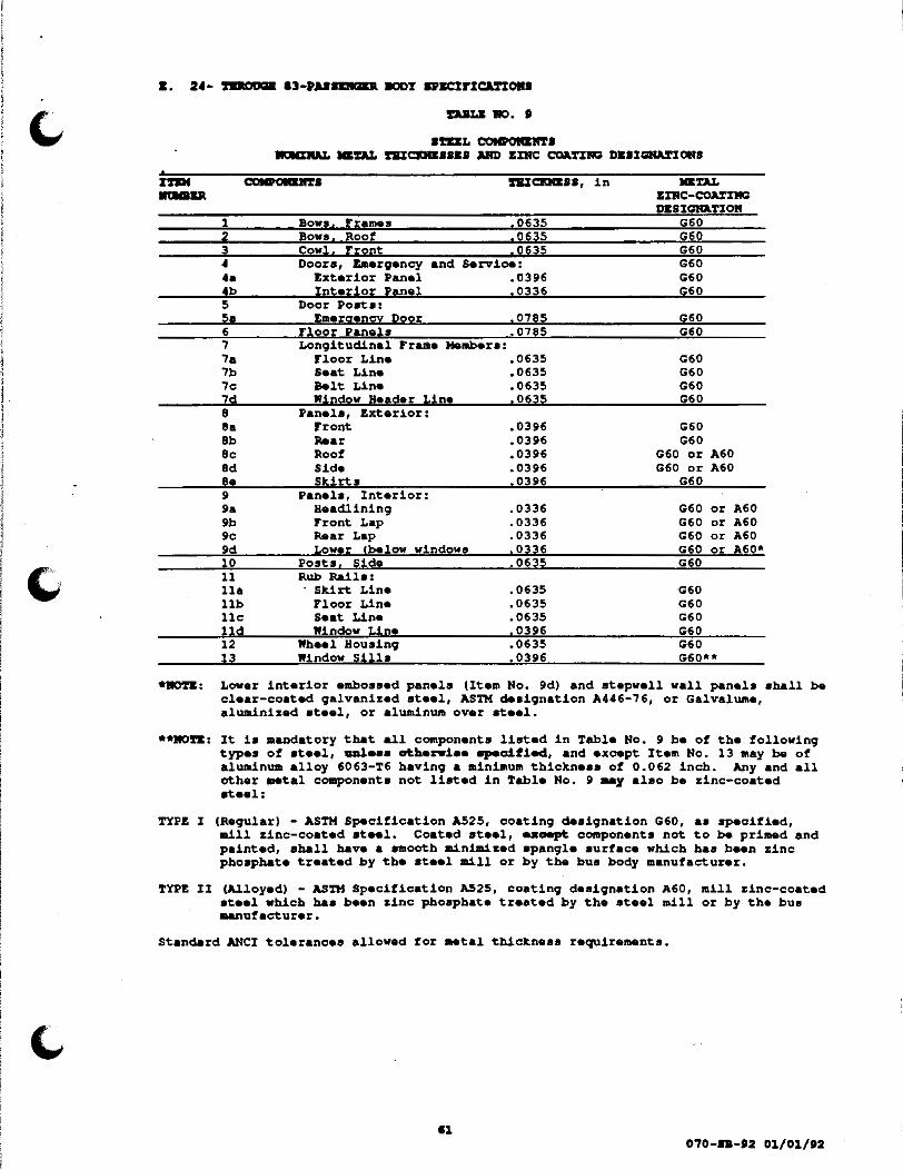
"
li.
3 ~
•• 4b 5 Sa 6 7 7& 7b 7c 7d e ea 8b ec ed ee 9 9& 9b 9c 9d 10 11 11& 11b 11c lld 12 l3
DaLK 110 ••
lftliL COIIPOIUII'l'l lll!llaK.'IL .. DL nJ:aaal&lil Alii) ZIRC c:oa.nJC DliSIGIIIM'IOHS
Zxterior Panei and • 0396 ~=~ Interior Panel . 0336 G60
Door Poata: berqeney poor
Floor Panels Longitudinal Frame
Floor Line Seat Line Belt Line
.0785
.0785 Member a:
.0635
.0635
.0635
.0635 Window Header Line Panels, Exterior:
Front Rooar Roof Side Skirts
Panela, Interior: Headlining Front Lap Rear Lap Lower lbelow windows
Posts. Side Rub Railo:
Skirt Line Floor Line Seat Line Window Line
Wheel Housing Window Sills
.0396
.0396
.0396
.0396
.0396
.0336
.0336
.0336
.0336
.0635
.0635
.0635
.0635
.0396
.0635
.0396
G60 G60
G60 G60 G60 G60
G60 G60
G60 or A60 G60 or A60
G60
G60 or A60 G60 or A60 G60 or A60 G60 or A60* G60
G60 G60 G60 G60 G60 G60**
•ROTE: Lower interior embossed panels (Item No. 9d) and atepwell wall panels shall be clear-coated galvanized steal, ASTM designation A446-76, or Galvaluma, aluminized atael, or aluminum over ataal.
**MO~: It ia aandatory that all components listed in Table No. 9 be of the following types of steel, aal••• ~berwi•• _,-cified, and except Item No. 13 may be of aluminum a~loy 6063-T6 having a minimum thickness of 0.062 inch. Any and all other .. tal components not liated in Table No. P .. y also be zinc-coated steel:
TYPE I (Regular) - ASTH Specification A525, coating designation G60, as specified, .!11 zinc-coated at .. l. Coated steel, ea~ components not to be primed and painted, shall have a smooth minimized spangle surface which baa been zinc phoaphate treated by the steel mill or by the bus body manufacturer.
TYPE II (~loyed) - ASTH Specification AS25, coating designation A60, mill zinc-coated steel which baa been zinc phosphate treated by the steel mill or by the bua aanufacturer.
Standard ANCI tolerances allowed for .. tal thickness requirements.
070-.. -12 01/01/•2

2.1.3. Body-cowl Attachment -Buses equipped with chaasia manufacturer's cowl shall be furnished with the body securely attached to the rear tao• of the chassis cowl with a minimum of 9 bolts, nuts, and lock washers. On all such buses the junction between cowl and body shall be sealed to form a gastight and watertight seam. The sealant used shall be e~tbar the best grade of molded or extruded rubber weather stripping or a good quality, pressure applied, silicone elastomer sealant.
2.1.4. Bus Body Lenqth - The bus body shall extend to, or farther than, the end of the chassis frame ao that all main cross members and auxiliary cross members will rest upon the chassis frame. The distance from the end of the chassis frame and the rear of the body shall not exceed 6 inches.
2.1.5. Caulking -A flexible, tenacious, high quality caulking compound or adhesive ahall be applied to the top of all rub raila, all unwelded metal joints, and to any place where moisture could enter througb the exterior panels. This doea not include the fresh air intake or heater or drain openings at the bottom of the rub rails. The compound aball ._ applied to the required areas in a neat and workmanlike manner without voida or akips.
2;1.6. Chassis Frame Alterations - The body manufactux.r •hall not in any manner alter the 24- through 83-pa•senger chasais f~ except to cut off the rear portion of the frame where necessary to weld ba.per braces, and to lengthen the frame in order to comply with the require..ats of Par. F.3.1. None of the rivets in the chaasia frame shall be cut flush ~th the frame or removed. The body manufacturer may alter the chassis frame to adapt standard chassis to forward control. (Any change must have body .anufacturer's warranty.)
2.1.7. Exhaust Pipe Extension- The body manufacturer ahall furnish and install an exhaust pipe extension when necessary in order to insure compliance with the chassis requirements of the exhaust system ( ... Pa~. r.5.5.). The tail pipe ahall not extend beyond the rear bumper.
2.1.8. Fasteners, Bolta and Rivets -All bolts and ri:wets used in the manufacture of J the school bus body shall be high strength metal. All bolts shall be equipped with lock washers or other acceptable devices to prevent loosening under vibration. All bolts, nuts, and washers except U-bolta, their nuts and washers, shall be parkerized, cadmium-plated, or otherwise rustproofed.
2.1.9. Fasteners, Other - Sheet metal screws or self-tapping bolts of any type shall not be used in the construction of bodies except:
2.1.9.1. ~ignment* of doors or in conjunctiDD with rivets, wel~, or bolts for compliance with FMVSS No. 221, as applicable, or,
2.1.9.2. Attachment of exterior mirrors in certain c•••• (aee Par. E.3.8.S.),
2.1.9.3. 2.1.9.4. 2.1.9.5.
2.1.9.6.
2.1.9.7. 2.1.9.8.
or, Electrical wire moldings and light ~ixtur•a Installation of header pa~ over the doors, or Installation of rub rails or emergeacy door handles and latches where it is impossible to use riveta or bolts, nuts, and lock washers and then only when these fa~nera are used in conjunction with the manufacturer's atandard metal adhesive which ia used to meet joint strength requirements, or, Interior panels which must be removed to give accessibility to other interior or concealed components, or, Seat construction (See Par. &.2.13.5.2.), or, Window frames when applied with ~he .. tal adhesive.
*Kben self-tapping bolts are uaed to align doors, they shall be tack-welded at the head or applied v~th the metal adhesive and shall not exceed the number of rivets, or bolts, nuts, and washers inatalled in the door binges.
2.1.10. Front Body Section, Semi-forward Control Bodies - On semi-forward control 24-through 71-pasaenger buses, the front body section of the school bus from the win~hield forward aball be of the bus body manufacturer's standard design and shall contain, but not be limited to, the fo~owing components:
2.1.10.1. Fenders - Properly braced fender• w~th the total apread of the outer ~ edge• exceeding the total spread of ~be front tires when the front ~ wheels are in the straight-ahead position.
12 070-88-·2 01/01/,2

'
•• 2~1.10.2. Gr~lle - A sufficiently reinforced grille aaaembly.
2.1.10.3. Rood - Rood cover with latching .. chaniam providing acceaa to the forward part of the engine.
2.1.10.4. Lamps - Beadlampa and parking/turn-aignal lamps as required by FHVSS No. 108.
2.1.11. Fuel Filler Opening - The body aanufacturer will provid8 an opening in the body panel of auffici•nt ai~• to allow easy ace••• and entry of fuel nozzle to the fuel tank filler neck opening. i'hia opening in tba panel must be so positioned that the filler neck, vban viewed at right an91aa from the side, ia approximately centered in the cut -out. This opening shall be provided vi th a hinged cover ao designed and conatructad to r.main open when fueling is in prograaa and r ... in in a totally clo .. d position at all other times C••• Par. J:.2.10.3.l.J.
2.1.12. I~ntification Plata -Each body ahall bear in a prominent place a permanently attached plate abowing the name of the manufacturer and the body aerial number , ..... z. & .•.•. 2.).
2.1.13. Steering Wheel Placement - Tbare shall be at least 2 inches clearance between the ateerinq wh .. l and the cowl, instrument panel, or any other surface.
·2.1.14. Wood- The uae of wood shall be limited to the construction of passenger seats, aeat backs, or header pads, and the bottom of any tool compartment or to insulate floors.
2.2. ACCZII •ARELS - Any panel used for access to the engine radiator or radiator overflow container and installed in the passenger compartment ahall have a keyed lock. (This does not include the enqine cover.)
2.3 ~ caMP~ - If the battery is mounted on the chassis frame (which ia required on dieael-powered buses), the bus body manufacturer shall provide a battery compartment beneath the floor of the bus body. This compartment shall be a skirt type container, reinforced and equipped with a pullout receptacle and an outside access door. The battery compartment shall provide complete weather protection for the battery as well as total access for servicing (a .. ••r. r.4.2.4.). aattery oab1•• o~ aa~~J.ai.eDt l.ell¢b abal.~ be prOYi.cl.ad to aaoo.aodate tlae •oantia9 o~ tbe battezy .111 tb.i.a aa.partaeat, -d tlae body a&Dafacrtarer abal~ •01Ult tU battery i.a tbe 0011paz1:.aarat. ft.ia o011p&Z'1:..at i.a aot. a...Uabl• OD ~•z- •DCJ.!.De buaea •
2.4. •cor rRANK - The complete body frame shall be formed, welded, riveted, or lock bolted, assembled and constructed in accordance with recoqnized engineering practic•s within th• bua body induatry.
2.4.1. Design - The frame ahall have a formed ahape with a minimum cross ••ctional depth of 1-1/8 inches. Frame members, running from one aide main erose member to the other •ide main croas aember, may be continuous bow frames, or they may consist of aide posts and roof bows. If aide posts and roof bows are usedr every pair of aide posts must be connected by a roof bow to form the equivalent of a continuous bow frame. The aide posts ahall be set on not more than 30-iDab centera, except that one aide post and bow or one bow fra-. may be .. t on a aaximum of 38-3/4 center, or three bow frame sections not exo .. ding 36-1/2 inches may be used in any one body (up to four 38-3/4 inch body fr ... sections aay be used for Forward Control Rear Engine buses ONLY). Each of the aide posts or bow frames shall be aecurely welded, rivatad, or lock bolted to the floor ayatem at each main cross member or to the longitudinal frame .. mber which is located at the floor line. Each aide post and/or bow frame must also ba attached, as specified above, to the remaining lonqitudinal frame .. mbera.
2.4.2. Front Frame Section - Tha front frame shall be a unitized framework of formed sections designed with the necessary atreas members required to withstand the torsional stresaes aet up by or in the chassis. The corner posts shall extend from the bottom of the body to the vin~hield header and shall not causa or produce a •blind spot" for the driver. The front assembly shall ba securely attached to the floor system by lock bolting, welding, or riveting and shall be aecurely bolted to the chassis cowl in such a manner as to not to causa undue atrain (sea Par. £.2.4.1.).
113 o1o-••-•z 01/01/•2

2.4.3. Longitudinal Frame Members - The body frame shall have not less than four individual aide iongitudinal frame .. mbera extending the full length of the body (except as interrupted by aida posta or when cut for an opening for the wheelhousing) • ODe eaab •ball be 1ooated at ~ f~oor 1~, tb• •••t 1iD•, 1:.be belt 1iae, aad at: 't.be wiDdow beader llae. The belt line longitudinal member may be replaced by an exterior rub rail, i.e., an extra rub rail in the belt line area. This rub rail shall •eet requirements specified under ROB aAILI, Par. K.2.10.
2.4.4. Material - The body frame ayatem (see Par. !.2.1.1.) ahall be of the type, grade, and thickneaa of steel specified in Table No. 9 or approved equal, and shall ... t the requirements of FMVSS No. 220.
2.4.S. Rear Frame Section - The rear frame ahall consist of a formed aill, two posts (one on either aide of the emerqency door, extending from the sill to the roof
bow and intersected by a rear header at the proper point), and suitable strainers to form a rigid tramework. This framework ahall be aaaembled and attached to the floor system by welding, riveting, or lock bolting.
2.5. KNKRGZRCY &X%T8 - Texas achool buses shall be provided with emergency exits as listed below:
2.5.1. DCZRQDI'CY DOORS - The emergency door shall be of the type, grade, and thickness of steel specified in Table No. 9 or approved equal. Emergency doors on buaes furnished to this specification shall be equipped with doors meeting the requirements below. Emergency doora shall be furnished with upper gla~s panels, permanently closed, aet in rubber or sealed against rubber. (See Par. £.2.19.2. for glazing requirements and.Par. £.1.4.4. for lettering.)
No seat or other object shall be placed in the body that restricts the · passageway to the emergency door to less than 12 inches. There shall be no steps leading to the emergency door.
2.5.1.1. Attachment - The hinges for the emergency doors shall be attached with rivets or bolts, nuts, and lock washers. ~tal •c~•• o~
~e1~-'t.appia9 bolt• are aot aaaeptab1e. Metal screws aay be u••d for alignment of doors while in•ta11LD9 ri..t•. Self-tapping bolts may be used for alignment ~~ the bolts heads are taok-weldad to the hinges (see Par. E.2.1.9.1.).
2.5.1.2. Design - The emergency door on all except rear-engine buses* shall be located in the center of the rear of the body and shall have a minimum horizontal opening of 30 inches and a minimum vertical opening of 48 inches measured from the floor level. The door shall be hinged on the right aide of the body (~orward aida ~or r.ar an9iae buaea), shall open outward, and shall be designed to permit opening from both inside and outside of the bus. It shall be properly sealed against moisture and dust.
2.5.1.3.
2.5.1.4.
*A left rear emergency door meeting the requirements of FMVSS No. 217, shall be provided on rear engine buses.
Door Bolding Device - A aeans (device) shall be provided to hold the awing-out type door(a) in the tully opened position· (90° minimum).
Glass Panels - The glass in the emergency door shall have an area of not less that 299 square inches and shall be set solid in a waterproof manner (see Par. E.2.19.1.1.). The installation of glass in the lower portion of the door is required and shall meet the same requirements (lower glass panels aot required in the emergency doors of rear engine buses) • The lower glass panels shall be the body manufacturer's standard size. These glass panels shall be installed securely to prevent remova~ by hand.
2.5.1.5. Seader Board- The head impact area on the inside at the top of the emergency door shall be protected by an energy-absorbing, padded header board, 3 inches wide and one inch thick, eAtending the full width of the emergency door to prevent injury when accidentally impacted.
070-BB-·2 01/01/'2

2.5.1.6. Latch- The emergency door shall be equipped with a alid• bar rack and pinion (cam) operated latch. The alide bar shall be approximately 1-1/4 inches wide and 3/8-inch thick and shall have a minimum atroke of l-l/8 inches. The elide bar shall be spring loaded ao aa to retain the bar in the closed position and have a minimum of one inch of horizontal bearing surface beyond the edge of the door frame when the door lock ia in a latched position.
2.5.1.7. Latch Randle- The aovement of the lock handle through its full arc of operation ahall not be obstructed by, or extandad into the area behind the rear aeata at the emergency door. The handle, when in the closed position, shall meet the requirements of FMVSS No. 217. !be dasign of the latch handle ahall allow quick release, but shall offer protection against accidental release. Control of the fastening devices from the driver's aeat shall not be permitted. A pull handle shall be installed on the inside of the emergency door so that tbe door can be securely closed for positive fastening. Provisions for opening from the outside shall consist of a handle (device) designed to prevent "hitching a ride" yet allowing the door to be opened when necesaary. The out aide handle, when in the closed position, shall extend vertically downward from ita pivot canter.
2.5.1.8. Switch - The emergency door latch shall be equipped with a heavy-duty electric plunger-type switch connected to a warning buzzer located in the driver's compartment. The switch shall be enclosed in an adequately protected case, and wires leading from the switch shall be concealed in the walls. The switch shall be mounted plumb, parallel, and perpendicular to the striker plata of the lock slide bar. The awitch shall be installed ao that the bu;zer will aound before the door handle ia turned far enough to permit the door to open. The switch shall be Cole-Heraee'a No. 9118, having an upset end (knob) on the plunger head.
2.5.2. Side Emergency Exit• and Roof Hatches - Texas achool buaea ahall be provided with side emergency exits and roof hatches. These aide emergency exits may be either aide emergency doors meeting the requirements of Par. £.2.5.1. above (except that they shall be hinqed on the forward aide} or they may be push-out type aide windows •eeting the requirements of Par. £.2.19.1.5. and FMVSS No. 217. Single emergency exita ahall be installed near the center of each aide, except that on Type 0 buses, they shall be installed near the center of each side, but in the rear portion in accordance with Federal Standards. When ao ~oLfLed iA ~ ~~~a~LOD for aide (a .. OptLOD 3D), additional pu•h-out windows shall be furniabed (quantity shall be apecified by school district) • Two or more emergency exits per aide shall be as •equally spaced" as practical. Roof hatches shall be the body manufacturer's standard. They ahall be equipped with an external and internal handle. Texas acbool buses shall be provided with minimum aide emergency exit• and roof hatches as follows:
Up to 22-paaaengera 23- thru 65-pasaengera Larger than 66-paaaengera
1 emergency exit per aide aDd 1 roof hatch 1 emergency exit per aide and 2 roof batches 2 emergency exits per aide aad 2 roof hatches
z.c. FLOORa - The floor ayatem ( .. e Par. £.2.1.1.3.) shall be of the type, grade, and thickness of steel specified in Table No. 9 or approved equal (a .. Par. E.3.1. for requirements for access port to fuel aending unit) •
2.6.1. Constru'ction and Inatallation - The floor panels ahall run the full width of the floor and shall be supported on all outside edges by a longitudinal frame .. mber. The floor panels shall be welded, riveted, or bolted to the main and auxiliary cross members and shall be joined so aa to form a leakproof and dustproof floor. The main and auxiliary cross members ahall extend the full interior width of the floor panels. The aide posts or bow frames shall be aecurely welded, riveted, or bolted to the floor aystem and to the longitudinal frame members or guaseta.
070-88-12 01/01/12

2.6.2. Cross Members - Tbe cross .. mbera shall be apaced not more than 10 inches center-to-center. The floor panels and cross members shall be designed ao as to completely and adequately support all fixed and changeable loads under all operating conditions without deformation of the underbody structure, strains to body, or fractures of member joints. The design and strength of the understructure shall be sufficient to eliminate the necessity of installing outriggers attached to the chassis except at the front entrance. The undersurface of tbe entire floor structure, including wheelhousing and atepwell, ahall be aprayed with aaterial at least 1/8-inch thick conforming to that •peciried in Par. E.l.ll.
2.6.3. Ina~atioa - Wben air conditioning is ordered (aee Option No. 1 and Par. B.1.2.) the floor ahall ~ covered with 5/B-inch nominal thickness A-C or B-8 exterior grade plywood manufactured in accordance with O.S. Product Standard PS 1-83. COX interior grade plywood with exterior glue is acceptable when all surfaces including the edges of the wood are covered or aealed against the exterior environment. See Par. C.2.5.1. for plywood installation requirement a.
2. 7. rLOOa COYD%RO -
2.7.1. Aisle Material - Floor covering in the aisle shall be the aisle type, fire-resistant rubber or equivalent, and shall be nonskid, wear-resistant, and ribbed. Minimum overall thickness shall be 3/16 inches when measured from tops of the ribs. Rubber aisle floor covering shall meet Federal Specification ZZ-M-710.
2.7.2. Installation- Floor covering (except that on the toeboard) shall be permanently bonded to the floor with waterproof adhesive material and shall not crack when subjected to sudden temperature changes. ~l seams shall be sealed with waterproof sealer.
2.7.3. Trim - Seams shall be covered with extruded aluminum metal strips of a minimum 3/16 inches high and 1 inch wide that shall be installed on each aide of the aisle, the full length of the aisle, ao as to secure both the edges of the aisle covering and adjoining edges of the underaeat covering. Each aisle strip shall consist of not more than three pieces of the metal stripping. The strips shall be secured to the flooring with ~lush-mounted flat or low profile oval head screws; holes for the screws aball be countersunk. The screws shall be placed not more than 9-inchea apart for the full length of the metal strips except that the ends of each piece of stripping shall have screws placed at not more than 3/4 inches from each e~d. Screws may be placed 9-l/2 inches apart only to avoid interference with floor sill members.
2.7.4. Onderaeat Material- The floor in the underaaat area (including wheelwells, and the areas under the driver'• seat, wheelchairs, and toeboard except transmission inspection plate) shall be covered with fire-resistant rubber floor covering or equivalent having minimum overall thickness of l/8 inches. Floor covering on toeboard shall be held in place by trim strip or molding.
2. I • I'ARIILS, &UU%011\ -
2.8.1. Attachment and Installation -All exterior panels shall ~ attached to bow frames and strainers ao aa to act as an integral part of the structural frame. They shall be installed by lapping and riveting, lapping and bolting, or by ~langing and bolting and in such a manner as to ~o~ watert~9bt joLnt•. The exterior aida panels shall be installed either vertically or longitudinally. Vertical panels shall be one-piece and ahail extend from the window line to or below the floor line. Longitudinal panels shall be installed starting at or below the floor line and extending upward to the window line with each ascending panel overlapping the preceding panel. Rub rails shall not be considered aa part of the paneling for covering the aide exc•pt for press•d-in window rails.
2.8.2.
2.8.3.
Design - The front and rear exterior panels shall be formed contours to give a smooth, pleasing appearance to the bus. exterior roof panels shall be of not more than three pieces together to form a continuous piece over the front and rear
into the desired The front and rear welded or riveted frame.
Joints - Joints ahall meet the requirements o! FMVSS No. 221.
2.8.4. Material - ~l exterior panels (see Par E.2.1.1.2.) ahall be of the typ4, 9ra_c:le, and thickness of ateel specified in Table No. 9 or approved equal.
070-IB-P2 Ol/01/P2
J

2.8.5. Undercoating - A1l exterior panels shall be completely sprayed on the inside of the ~n expoaed surfaces, and shall featheredge to the edge of the attaching .. mbers, with 1/16-inch thick aaterial conforming to that specified in Par. E.l.ll. The apraying aball be done after the panels are installed.
2 .I. PADLI, Dft'D%01\ - All interior wall and ceiling panels shall be steel and of the body manufacturer' a atandard design except the panel• beneath the windows ahall be clear-coated 9alvanized embossed steel .. eting ASTM A 446. Also the atepvell and riser panels in the aervice door entryvay shall be clear-coated galvanized ateel (embossing not required). Galvalu.e, aluai~zed ateel, and aluminum over ateel panels are acceptable for v:ae beneath the windows and in the entryvay.
2.9.1. Attacb.ent - A11 interior panels shall be attached to the frame structure by bolts, rivets, or by any well-designed method utilizing self-locking panels, or locking panel .trips. ~gardleaa of the aethod used, the panels ahall be attached so that vibration, rumbling, and popping will be at a minimum.
2.9.2. Design - Front and rear panels ahall be formed to present a smooth, pleasing appearance. If the ceiling ia constructed ao as to contain lapped joints, the forward panel ahall be lapped by the rear panel and all exposed edges shall be beaded, hemmed, flanged, or otherwiae treated to minimize sharp edgea.
2.10. 1\08 RA%LS - Four aeparate, one-piece, continuoua rub raila of the type, grade, and tbicknesa of ateel specified in Table No. 9 (or approved equal}, ahall be installed on
-the body aa deacribed below. The minimum finished width of all rub rail• ahall be 4 inches:
2.10.1. Construction - The rub raila ahall be of ample strength to resist impact and to prevent crushing of the bua body and ahal~ be a f~anged-formed channel, longitudinally f~uted or corrugated rib surface. Ends shall be (1) smoothly closed, or (2) closed by a rounded end cap which shall be butt- or flash-welded to the rub rail, or (3) closed by a rounded end cap inserted with an approximate one-inch sleeve inside of the rub rail, riveted in position at the top and bottom of the rub rai~ flange, and aealed in the aame manner aa the top flan9• of the rub rails.
2.10.2. Drainage - The bottom edge of each rub rail (except the pressed-in-type which may be uaed near the window line) ahall have provisions for drainage of accumulated moisture. One of the following drainage methods shall be used:
2.10.2.1. Slota - The bottom flange of the rub rail ahall have a minimum of one inch by 0.32 inch for.ed alota apaced on not more than 12-inch centera, or
2.10.2.2. Slots or Slota - One 1/4-inch diameter slot or hole per foot in the loweat part of the rub rail CJ.ll.cl p~J.•~ ~o i:be pz-J.ai.Dv, pai.at.i.D9, aad i.Dft.Uc.l."" of ~ ... &'all "'all aball ._ P"'O't'.l..-d, Holes drilled after rub rail installation or after priming and painting are D~ acceptable. ro~d a1fta azoe ... feccecl OOYeZ' ckJ.lled. or cnft .b.ol••.
2.10.3. Insta~lation - All rub rails ahall be bolted or riveted on top and bottom to each aide peat and riveted on top and bottom to the exterior paneling between the aide poata (aee exception in Par. E.2.1.9.5.). Provisions for one-piece rails may be acoompliahed by butt- or flaah-weldinq. ~1 weld4, including those for the end capa, ahall be dreaaed, sanded, and buffed. Thea• rub rails shall be installed on both aid.s of the bus body aa follows:
2.10.3.1. Floor and Skirt Level - The floor and skirt level rub rails and the additional rub rail furnished in lieu of one longitudinal frame .. mber shall be installed the full outside length of the body (except at wbeelhousinga) on the right aide from the service door to the rear corner radius and on the left aide from the point of curvature near the outaide cowl to the rear corner radius. One of the floor level rails aay be ~ to provide an opening for the qaa tank filler neck oDly if fuel tank furnished to meet FMVSS No. 301-75 requires the opening to be enlarged, or to meet the requirements in E.2.1.ll.
070-aB-12 01/01/12

2.10.3.2. Seat Level - The aeat level rub rail shall be installed from the aervice door completely around the bus body (•xcept for •mergency door and rear engine bua) to the point of curvature near the outside cowl on left aide. The raila may be two-piece with the joint being near the rear aide of the bus body. The rail extension shall be joined to the continuous aide rail by one of the following (1) butt welding, (2) jogged lapped by not less than one inch and riveted, or (3) butted with a aleeve riveted over the joint. When joining is by lapping or fastening with a aleeve, the joint must be made at the rearmoat body aide post or preferably, the ••cond post from the rear.
2.10.3.3. Window Level - The window level rub rail ohall be installed the full outside length of the body on the right aide from tbe aervice door to the rear corner radius and on the left aide from the point of curvature near the outside cowl to the rear corner radius. The splice, if necessary, shall be located at the body post behind the rear wheelhouse, ·by lapping the full width of the supporting part of the post.
2 •. 10.4. Location - One rub rail shall be installed at the skirt level, one at or near the floor, one at or near the seat level, and one near the window line. One additional rub rail may be furnished in lieu of one longitudinal frame member (aee Par. £.2.4.3.).
2.10.5. Sealing - The top joint of the rub rail shall be sealed with a caulking compound or adhesive as specified in Par. E.2.1.5.
2.11. ·~ &ARR%&Ra - Seat barriers ahall be furniabed and installed in accord4nce with FMVSS No. 222. The front barriers shall not infringe upon the area required for safety and operating equipment.
2.11.1. Handrail -A grab handle or handrail of sufficient length to assist entering and exitinq passenqers shall be installed on the forward aid• of the right barrier. The outside surface of this handle shall be stainless steel, polished aluminum, or chrome-plated steel. (see Par. C.2.14.4.)
2.11.2. Knee Space - knee apaoe between these barriers and the front of each front passenger seat shall be at least 24 inches for 24-passenger bus, at least 24-3/4 inches for the 715- and 83-paasenger buses, and at least 25 inches for all other 35- through 71-paaaenger buses when measured from the modesty panel to the front of the seat back at the center of the seat approximately 4 inches above the seat cushion.
2.11.3. Upholstery - Barriers shall be covered with upholstery meeting the requirements of Par. C.2.12.3.6.
2 .12 • IU!l"IIIQ DQUIUIIP'fl, DJUWa -
2.12.1. Design- The base of the driver'• seat aball be of the adjustable pedestal type or the platform type having an adjustment range of approximately 4 inches wFore and Aft,w aad a aeparate minimum one-inch vertical adjustment. The back of the driver' a aeat shall be heavily padded and form-fitted •.
2.12.2. Driver's Sigh Back Seat, Optional- WbeD •o apeci~~·d ~ ~. XaY~~at~oa ~or ~d., a high back driver's seat shall be provided with a minimum seat back adjustment of 15 degrees and with a head r•straint to accommodate a 95 percentile adult male Cas defined in FMVSS No. 208) and shall meet all of the applicable requirements of Par. E.2.12.1. above.
2.12.3. Driver' a Seat Aoceaa - There shall be unr•atricted access to the driver's seated position from either the aisle or the right service door without the operator having to climb over the engine cover or any other object. The minimum apace between the driver' a aeat (in the r•armost position) and the engine cover or other object (exc•pt aeat belt anchorage) at the floor and at the aeat level shall be not less than 6 inches.
2.12.4. Installation - The pedestal or platform shall be mounted with bolts, flat washers, lock washers, and nuts except where it ia impossible. to use bolts and nuta at certain floor points due to main cross mambera or floor sill interference. Tbread-tormin9 or cutting bolta and lock washers may be used at tbeae points.
••

I l l
l I I
I i I '
I I
i '
2.12.5. Seat Belt• and Seat Belt Assembly -A Type 2 ••at belt assembly conforming to FHVSS No. 209 shall be provided for the driver. The belt assembly shall be equipped with at least on• reel-type emergency lockinq retractor CELR) for the continuous belt assembly. The location of the ••at belt anchora9• shall conform to SAE Standard J383 with the driver's seat adjusted to ita rearmoat position. The anchored en~ of the belt assembly shall be fitted with a min~um e-inch semi-rigid plastic boot which will prevent that portion of the belt between the buckle and the retractor reel from contacting the floor and to keep the belt from hitting the feet of the passengers in the front seat directly behind the driver. The seat belt assembly shall be anchored in such a manner or guided at the •eat frame eo as to prevent the driver from sliding a~dewaye from under the belt.
2.13. •KA%IMG a&QOlM&W&NX•, •ASSKRO&R - The bus passenger seats shall meet or exceed the knee spacing and crash protect~on requirements of FHVSS No. 222 and shall conform to the foUowingo:
2.13.1. Seat Back Heights - ~ •o ~olf~~ iD ~be lDTL~.~~OD ~o~ a~d. (see Option 21), aeat back heights shall be increased 4 inches over the seat back heights required by FMVSS No. 222.
BOrE: Seat backs with thia option will have heights of approximately 28 inches.
2.13.2. Seat Belts, Passenger, Optional - Caee Par. E.3.13.).
·2.13.3. Seat Cushions -All 26-inch and all 39-ineh seat cushions shall be designed to adequately support, respectively, tvo and three passenger of 120 pounds each. All seat cushion materials shall meet or exceed the requirements of FHVSS No. 302 and/or California Technical Bulletin 117. The seat cushion shall be either of one-piece construction or may be constructed of more thari one piece at the manufacturer's option. The seat cushion unit shall consist of a base, a one- or two-piece polyurethane foam cushion, and upholstery, meeting the following requirements:
2.13.3.1. Base - The base shall be nominal 1/2-inch thick, interior grade, c-o plywood with exterior gra~ glue, identification index 32/16, manufactured in conformance with U.S. Product Standard PS 1-83 and identified as to veneer grade and glue bond type by the trademarks of an approved testing agency. P~ywood -~~b b~ue ataiD iD aapwood ~· aot. aooapt:.ab~•.
Alternatively, the baa• may be made of "Donnite" material, manufactured by the Donnit• Corporation, Flora ' Harrison, Plymouth, Indiana 45563, of equal or better atrength and thickness.
2.13.3.2. Foam Cuahion Aaaembly, One-Piece Polyurethane Foam
03/2S/t2 - Cho ;.d by Aa. 11
Ci) Construction - '.l'he aeat cushion dimensions sh~ll be in accordance with the nominal dimensional requirements as shown in Fig. 2.
Cii) Desiqn - '.l'be one-piece foam cushion ahall be solid polyurethane foam conforming to the physical requirements in Table No. 10 (rebonded or •olded polyurethane foams are not acceptable for ••at cushion) •
I'l"DI
DJILI: ftC). 10
OKI-PIZCI COIRIOR PR%1ICAL PROPERTIES
(ASnl D 3574)
Density, lbs/cubic foot, Min
0111:-PIZCI 8D.T COSRIOR
Load Deflection, 4" thick @ 25% Indentation, Hin Indentation Load, Ratio, 65,/25,, ~n Compression Set, 50% Deflection (22 hrs@ 158°F), Max. Tensile Strength, lbs/aquare inch. Min
1.8 90
2.3 20 10
150 1.5
Tensile Elongation, %, Min Tear Resistance. lbs/inch. Hin
070-8B-t2 01/01/t2

2.13.3.3. Foam Cushion A•aembly, Two-piece Polyurethane -
(i) Construction - The seat cushion aaaembly shall be fabricated in accordance with the nominal dimensional requirements as •hown in Fig. 2. In the two-piece assembly, the top 1-1/2 inches of the cushion shall be of one continuous foam piece. ~1 parts of the seat cushion and the aeat atiffenera ahall be aecurely cemented or otherwise bonded together to form the aeat cushion assembly ahown in Fig. 2.
(ii) Design - The tvo-piaoe foam cushion assembly shall be constructed of unfilled polyurethane foam conforming to the physical requirements in Tabla No. 11 (~on~d po~yar.tbaD• fo ... •~ DOt aaa.ptab~• for •••t aa•hion or •••t .tLffea.r•):
'li!AIILII: ItO • 11
~-•Izca COSBIOft A8SZMIILY •nuCAL nm>uriu
(ASTM D 3574)
SEAT COSBION
I EAT STIFRNI:RS
Density, ~be/cubic foot, Min 1.8 52 ±5 2.3
10 10
150 1.5
2.4 80 Load Deflection, 4" thick 8 25' Indentation Min
Indentation Load, Ratio, 65,/25,, ~n Compression Set, SO' Deflection (22 bra 8 l58°F),_Max. Tensile Strength, lbs/square inch, Min Tensile Elongation, %, Min Tear Resistance. lbs/inch. Min
2.13.4. Seat Frames -
2.5 20 12 75
1.5
2.13.4.1. Design and Material - The aeat frames shall be constructed of steel Of the type, size, and gauge necessary to meet the seat load ~flection requirements of FHVSS No. 222. Seat frames legs shall be two, four, or six pedestal type. The seat backs shall elope backward to provide a comfortable seating angle. 8•at back• tbat •~ •et i.D a .-rtJ.oal plAIM or: 'tllt fo:nrar:d ar:e acrt aooeptabl•.
2.13.4.2. Painting Requirements - The entire aeat frame, except that aection of the back frame which is padded and upholstered, shall be thoroughly cleaned, primed, and painted. The paint shall have adhesive qualities which will not permit the removal of the paint by means of the thumbnail-scratch aathod without first chipping a starting place ~aee also Par £.1.10.).
2.13.5. Seat Installation -
2.13.5.1. Aisle Width - The minimum aisle width between rows of aeata shall be 12 inch•• except a 30-inch aisle ia required if regular seating is provided between the rear emergency door and any wheelchair positions on wheelabair-equipped buses (see Par. G.1.7.3.).
2.13.5.2. Attachment - Each leg shall be attached to the floor with at l•a•t 2 bolts, flat washers, lock washers, and nuta, or approved equal. Where it is impossible to use bolts and nuts at certain floor points due to aain oroaa members or floor sill interference, thread-forming or cutting bolts and loak waabera may be used.
2.13.5.3. ~ee Spacing- ~lowing for manufacturing tolerances, Texas requires the maximum allowable knee apace on buses conai-tant with the overall standard body lengths (a .. Par. A.2.13. for the definition of knee spacing and Option No. 15 tor increased knee apace on all 24- through 71-paaaanger buses). These ~nima are generally not lass than the following <••• Table No. 8):
03/25/t2 - Cbaaged by Aa. fl
(i) (ii)
(iii)
24 inchaa for the 24-paaaenger bus 24 3/4 inches tor the short wheelbase 71- and the 83-paasenger buaea. 25 inches for all other 35- throuqh 77-passenger buaas.
70 070-8B-t2 01/01/t2
J

I
I
I
I lc,
z.
SEAT CUSHION ASSEMBI..Y
j~·----------------~~-----------------~·1 26~" ----------------------- ------- ----------------------------------- -------- -----------------------------------------------------------
::=:=:=:=:=:=:===~~==:::::::=:~====~~~= _::::::::::::::=:=t=-:r~=:=:=:::::::::::::=t=:=:=:=:=: -------~:------------::~-~~~= ------------------------- ------------------ ------------------- --------
::E=~=~3E-!.f(L ~~~-=~~.::-=~~-:-:-:-: -----------
--------=~~~~~~~~~R:l ---------- -------------------· ------------------- --·----------------- ------------------- -------------------· --------
31~. --------01
1......-----18~ ·------1 FRONT VIEW
~----------------39~·
--------------------------------------------------------------------OR
26).£"
31~·
OR
-----------------------
18)1" -----....oo.! REAR VIEW
SIDE VIEW
71 070-a&-12 01/01/12

2.13.6. Upholstery - The ••at cushion and back units •hall be covered on top and four •idea with a vinyl resin-coated upholstering material as follows:
2 .14 • URVICJ:
2.13.6.1. Material - These materials shall be fire-resistant and shall meet or exceed the Boston Fire Block Test in the National School Bus Stanclarcl.a. They shall be artificial leather.
2.13.6.2. Thread- The upholstery material shall be securely sewn with a thread meeting the requirements of Federal Specification V-T-29Sd. The thread in the needle and the thread in the looper (bobbin) of double thread machines shall be •ize F, Type II (Twisted Bonded MUltiple Cord) , and aize E, Type I (Twisted Soft Multiple Cord) , respectively. The thread u•ed in the needle and through the looper •hall be Size F (Monofilament), Type III, for single thread machine•.
2.13.6.3. Welting- There shall be welting on exposed seams of the seat back and cushion.
2.14.1. Design of Steps - The entrance door steps shall be designed so that the first step shall be not less than 10 inches and not mora than 14 inches for Type A, B, and c buses and not leas than 12 inches and not more than 16 inches for Type 0 buses, from the ground when the bus is unloaded. Service door entrance may be equipped with two-step or three-step entrance. Risers in each case shall not exceed a height of 10 inches. When plywood is used on a steel floor or step, the riser height may be increased by the thickness of the plywood. (See Par. E.2.6.3. for material requirements.) The stepwell shall not protrude beyond the side body line and shall be fully enclosed to prevent accumulation of ice, snow, and dust.
2.14.2. Entryway Access - There shall be a minimum of 12 inches of unrestricted access from the service door to the center aisle.
2.14.3. Floor Material - All steps and the floor line platform area shall be covered with 3/16-inch rubber metal-backed treads with at least 1-1/2 inch white nosing as an integral piece without any joint. A three-inch white rubber step edge with metal back may be substituted in the floor line platform area. Step tread minimum overall thickness shall be 3/16-inch ribbed design similar to the ribbed design of the aisle rubber. Metal back of tread, minimum 24-gauqe cold rolled steel, shall be permanently bonded to ribbed rubber. Grooved design shall be •uch that said grooves run at 90-degree angle to long dimension of step tread. The rubber portion of the step trends shall have the following characteristics:
2.14.3.1. Show a Ourometer or equivalent hardness of 85 to 95.
2.14.3.2. Special compounding for good abrasion resistance and high coefficient of friction.
2.14.3.3. Sufficient flexibilatY oo thet it can be bent around a 1/2-inch mandrel both at 130 F and 20 F without breaking, cracking, or crazing.
2.14.4. Handrails - A grab handle not leas than 20 inches in length shall be provided and p~aced in an unobstructed location inside the doorway. The outside aurface of this handle shall be stainless steal, polished aluminum, or chrome-plated ateel (see Par. C.2.11.1.).
2.15. 8&RVXCK OR ~ DOORS - The service door shall be of the type, grade, and thickness of steel specified in Table No. 9 or approved equal:
2.15.1. Attachment - The hinges for the ••rvice or entrance doors shall be attached with rivets or bolts, nuts, and lock washers. ~ta1 •or.w• or .. lt-tapp~ng bol-t• an. Dot. aooept.altle. Metal screws .. y 1M a••d for alignment of doors w~le ~D.-tal1LDg rL.-"t•. Self-tapping bolts may be used for alignment ~t the bolts beads are taok-wal~d to the hinges (see Par. E.2.1.9.1.).
72 070-BB-12 01/01/12

I
'" I
2.15.2. Design - Tbe service doors aay be the folding type (i.e., open in the middle) or the folding (or jackknife) type. Tbeae doors shall have a minimum horizontal opening of approximately 24 inches and a minimum vertical opening of about 68 inches. Tbe service door shall have upper and lover glass panels <••• Par. £.2.15.3. below) to permit the driver to ••• entering passengers as well as the passenger landing area. Tb••• glass panels shall be ••t in rubber. Vertical closing edge or eciqea of the•• doors ahal.l be equipped with rubber or rubberized material to protect paaaenqera' finger a. There shall be no door on the left of tbe driver. This door shall have a positive latching .. cbaniam to el~nate the poaaibility of an inadvertent door opening during a frontal collision or roll-over.
2.15.3. Glaaa Panels - Service or entrance doors ahall have glass panels of approved •afety glaaa (aee Par. £.2.19.2. for installation requirements). Bottom of each lover glass panel ahall be not more than 10 inches from the the top aurface of the bottom atep. The top of each upper 9laaa panel ahall be not aor• than 6 inches from the top of the door.
2.15 .4. Reader Board - 'l'h• head impAct area on the inside top of the service or entrance door shall be protected by an energy-absorbing, padded header board, 3 inches hiqh and 1 inch thick, extending the full width of the opening, to prevent injury when accidentally impacted.
2.15.5. Location and Operation -
2.15.5.1. Conventional Bus Door• - The entrance doors for conventional buses shall be operated manually, or wbeD •o .,.oif~.d iD tbe InTitation for aida , ... Opt~OD 10), actuated electrically, or by air pressure or vacuum and shall allow manual opening in caae of an emergency. The door control shall be the hand lever type, driver-Qperated,· and shall be dasigned to afford easy release and to prevent accidental opening. The two-piece or folding type service door shall be located on the right aide near the front of the bus in direct view of the driver.
2.15.5.2. Forward Control Bus Doors - The doors on forward control buses shall De operated either manually or actuated electrically or by air pressure or vacuum, and ahall allow manual opening in case of an emergency. If manually operated, the door control shall be the hand lever type, driver-operated, and ahall be designed to afford easy release and to prevent accidental opening. The service door shall be located on the right aide near the front of the bus. At least two-thirds of its opening width ahall be ahead of the point opposite the back of the driver's seat. Wb8D •o .,-oifi•d in~ Ia.itat~oa for •~d. , ... OptLon 10), doors ahall be operated by means of electric, air pressure or vacuum, at the manufacturer's option.
2.15.5.3. Semi-forward Control Bus Doors - On semi-forward control buses, the entrance doors shall be operated from control• at or near the bus driver' a aeated position. The doors shall be operated manually, or actuated electrically or by air pressure or vacuum and shall allow •anual opening in case of an emergency. To prevent accidental opening while the bua ia in motion, the ayatem shall require at least a 125-pound force applied to ita center in order to. manually open the door. llblaD •o .pecd.fJ.ecl La 't:he lDYJ.t:atJ.oD for: aida , ... ~ion 10), door• ahall be operated by means of electric, air pressure or vacuum, at the •anufacturer'a option.
acrE: Powered Service Door• ahall be clearly and concisely marked with operating inatructiona in caae of a power failure.
2.1C. aK%Rr aKIMr~a - Si~ skirts shall be qusseted or braced on not more than 30-inch centers and wherever required for rigidity and to prevent vibration. If tb• 1:toc1y ..at.i.olaa an aatbo:r:i.s•cl to be l.onver t:b&D 30 i.Dabea, Do ao:r:e tbar:a th:r:- ••crt~ona o~ altirt: EeiD~o~Dt aball be OD oeat•r• ap to a ~ of 3& J.Dohea, o:r: DO ao:r:e 't.ban oDe -crtJ.oa abal.l be OD oautera ap 't.o a aa&J.aua of 38-3/• i.Dob••.
2.17. VKMTILA:IOR - The bus body ahall be equipped with a suitable, controlled ventilation system of auffici•nt capacity to maintain a satisfactory ratio of outside to inside air under normal operating conditione without opening window• except in warm weather. A static-type, nonclosabl• exhaust v•ntilator shall be inatalled in the low-pressure area of roof.
070-8B-t2 01/01/t2

2.18. w.z&LROOirRQ - The wheelhouaing aball be of the type, grade, and thickness of steel specified in Table No. 9 or approved equal. The wheelhousing shall be constructed of a maximum of three piecee and of arched deaiqn and shall be attached in auch a manner so· as to form a waterproof and duatproof aeam. The size of the wheelbousing shall be such that tire chains will have proper clearance. The edges inside the bus shall be rounded to prevent injury to the passengers. The wbeelbousing shall be such that when attached to the body, the strength of the resulting structure ahall be equivalent to or greater than that section of body that baa been removed to receive the wheelhouaing. (See Par. E.l.l1. for undercoating requirements.)
2.18. WIRDUDUI ARD W11iDOIII -
2.19.1. General Design -
2.19.1.1. Emergency Door Windows - Tbe emergency door ahall be furnished with an upper and lower glass panels (see Par. E.2.5.1.4.) permanently closed, and aet in rubber or aealed against rubber.
2.19.1.2. Rear Window - Rear windows Ca~ ... rg.aay door wiDdowa)* shall be installed on each aide of the rear emergency door. Each rear window glass shall have a minimum area of 140 square inches and shall be set solid in a waterproof manner. These windows shall be installed securely to prevent removal by hand.
*A rear "push-out" window, meeting the requirements of FMVSS No. 217, shall be provided on rear engine buses.
2.19.1.3. Side Window, Driver's- The driver's window aball be a 2-piece window of either of the following types:
(i) Two-piece eliding-sash type - This type will be acceptable only when the bus is equipped with an adequate air scoop to draw outside air into the driver's compartment. When the driver's ventilation is drawn through the beater system, this air shall be shielded from the heat sources and a hot water cut-off valve shall be provided in the driver'• compartment.
(ii) other Type - This type of window shall have the front part opening either in or out and rear part lowering and raising by use of a regulating handle.
2.19.1.4. Side Windows, Passenger, Standard - There shall be either a standard or a push-out type window for each passenger seat except where it is not possible because of the installation of aict. emergency exits (aee paragraphs E.2.5.2. and E.2.19.1.S.). Standard aide windows shall open from the top only and shall operate freely. A11 aide windows except the driver' a and the aervice door window, shall be the split aaah type with positive latch. Sid. wiDClowa 't.bat oaD M 1atabec:l iD aa aBaTeD. poaitiOD azoe Dot aooeptable. They shall be furnished with a latching mechanism which will allow each window to be latched in a position not more than aix inches from the top. The passenger aide windows shall provide an unobstructed opening 22 inches vide and between 9 and 10 inches high.
aorz: 77-passenger and 83-passenger rear-engine buses may have one lesa aet of paaaenger windowa than rows of seats.
2.19.1.5. Sid. Windows, Passenger, Push-out Type- At the manufacturer's option, 24-passenger buses may be provided with one push-out aide window iD lieu o~ an emergency exit on each aida and 35- through 83-pasaenger buses may be provided with two push-out aide windows in 1ieu o~ two emergency exita on each aide (see paragraphs E.2.5.1. and E.2.5.2. and Option 39). These windows shall be hinged at the top and aball be positioned for ease of egress. These push-out windows shall be the body manufacturer's standard push-out passenger windows meeting or exceeding Federal Standards.
7t 010-aa-12 01/01/12
J

~= Push-out windows shall be equipped with an electrical switch connected to an audible signal automatically operated and located in the driver'• compartment which shall indicate when the window ia pushed out in excess of 1/2-inch. The switch shall be enclosed to prevent tampering. Mires leadin9 from the switch shall be concealed in the walla. No cut-off switch shall be installed in the circuit.
2.19.1.6. Windshield- The maximum width of the windshield center post shall not exc .. d 2-1/2 inches. There shall be at least 2 inches of clearance between the steering wheel and the windshield, cowl, J.Datruaent panel, or any other surface.
2.19.2. Glazin9 - G1 .. a aball be installed in rubber channel gasket material or approved equivalent aaterial. The glass shall be mounted so that the peraanent identification mark ia visible from either inside or outside of the bua. All aafe1:y v1··~ aa1:ar.l.a1a &ball - app=-c! by 1:be DepaJ:1:-D1: of Pab11o 8af.ty. ~1 exposed edges of glaaa shall be banded. The glass shall be as follows:
2.19.2.1. Rear and other Mindowa - The glaaa in all other window including the driver's aide windows, emergency door windows, and rear {side) windows shall be a minimum of 1/8-inch aafety plate glass and shall be AS-2 grade or better as specified in ANSI Safety Code Z26.1.
2.19.2.2. Safety Plate Glass - Wben •o epeaified LD tbe XDYi~a~ion for Bida (see Option 16), all windows shall have AS-2 grade or better grade 1~ed safety plate glass.
2.19.2.3. Side Mindowa, Passenger - The glass in all passenger aide windows (including push-out type emergency exit windows) shall be a minimum of 1/8-inch safety plate ;lass and shall be AS-2 grade or bett•r, as apecified in ANSI Safety Code Z26.1 <••• Par. £.2.19.2.4.).
2.19.2.4. Windshield - The windshield ahall be minimum 7/32-inch thick safety plate glass and shall be heat-absorbent, laminated AS-1 safety glass meeting ANSI Standard Z26.1, as amended.
2.19.3. Tinting -
2.19.3.1. Side Windows, Passenger - Wben •o .,eoifi•d iD ~be InTitation for aid. (aee Option 16), passenger aide windows only shall be tinted to minimum 30,, maximum 40' light transmittance using AS-3 grade glass or better. This is defin•a aa •dark ~in~in9" and is not·p•rmitted on the windshield or any window used for driving purposes •
.:rl'K: All safety glazin9 materials aball be approved by the Department of Public Safety.
2.19.3.2. Windshield - The windshield shall have a horizontal gradient band (tinted) atarting slightly above the driver's line of vision with approximately 90' light transmittance and gradually decreasing to a minimum of 70' light transmittance at the top of the windshield, or the entire win~hield shall be tinted to meet the requirem•nta of FMVSS No. 205.
II. 3. Aca:SSOII%118, UQtiDiiD AIID OP'l"IORAL -
3.1. ACCKsa PaRr - An access port with cover plAte shall be installed above the fuel a•ndiftg unit. It shall be of aufficient aiz• to service fuel ••nding units and fuel pumps installed in tbe fuel tank. An access port is not required on the 24-paaaenger bus or on buses with front-mounted wh•elchair lifts (ae• G.1.7.3.).
3.2. ~ ALARM - An automatic, audible backup warning alarm meeting the r•quirementa of Type C, 97 dB(A), SAE J994b (except for 12-volt system) shall be installed behind the rear axle.
3.3. DzrROSrERS - D•froating equipm•nt shall k••P the windshield, the window to the left of the driver, and the glass in the service door clear of fog, frost, and snow, using heat from the beater and circulation from fans. All defrosting equipment shall meet the requirements of FHVSS No. 103. Any circulating fan used in defo9ging and inatalled on the curb aide of the bus front shall be mounted on the win~hield header so aa to protect the fingers, hair, and clothing ot •ntering and departing passengers.
070-BB-e2 01/01/e2

3.4. -IICT liiiOllliiUf - 24- throuqh 83-pauenqer achool buaes ahall be equippad with the follow~ng emergency equi~nt:
3.4.1. Body Fluid Cleanup IJ.t - Each bus ehall. be provided with a removable and moisture-proof body fluid cleanup kit. It ahall be properly mounted and identified as a Body Fluid Cleanup ~t. This kit shall contain as a minimum, the following itema mounted in a removable metal or hard plastic kit:
1 - 15 oz. chlorine-type absorbent daodorant material (or equal) 1 - 12 oz. germicidal apray disinfectant 2 - pair diapos&ble latex gloves 4 - 18" x 18" absorbent towels 1 - plastic pick-up apatula 1 - plastic band broom 1 - plastic dust pan 2 - 14" x 19• diapoaal bags and ties (waterproof) 2 - adhesive "BIO-HAZARD" labels 1 - 12 oz. deodorant apray 4 - individually wrapped, cold aterilization wipes in foil-lined pouches 2 - paper respiratory masks 1 - metal or bard p~astio container identified as waio-SA~" with black
symbo~ and lettering on orange mountable case
3.4.2. Fire Extinguiahera - School busea aball be equipped with a fire extinguisher, as ~isted below:
3.4.2.1. Standard Fire Extinguishers - Each bus aball be equipped with at ~east one refillable stored pressure Multipurpose Dry Chemical type (or approved equal) fire extinguisher of minimum 5-pounds capacity, mounted in an extinguisher manufacturer's automotive type bracket, and located in the driver's compartment in full view of and readily accessible to the driver. The fire extinguisher shall bear the Underwriters Laboratory Listing Mark of not less than 2A 20-B:C rating. Extinguishers shall be furnished with a hose, pressure gauge, and metal head.
3.4.3. Firat Aid Kit - Buaea.ahall have a removable metal first aid kit container aouoted in an accessible place within the driver's compartment. The compartment shall be marked to indicate the location of the kit. Number of units and contents for each kit shall be as follows:
2 - 1 in x 2 1/2 yda. adhesive tape rolls 24 - sterile gauze pads 3 in x 3 in
100 - 3/4 in x 3 in adhesive bandages 8 - 2 in bandage compress
10 - 3 in bandage compress 2 - 2 in x 6 yda. sterile gauze roller bandages 2 - nonaterile triangular bandage approx. 40 in x 54 in, 2 aafety pins 3 - sterile gauze pads 36 in x 36 in 3 - sterile eye pads 1 - rounded end aciasors 1 - pair latex gloves 1 - mouth-to-mouth airway
3.1, ~ ARD Jllix.ADD COIG'ORJ:lft'l -
3.6.1. Bleeder Valves - Any beater(s) installed by the body manufacturer shall have accessible air bleeder valves installed in the return lines.
3.6.2e Beater, Standard - Each bus shall be equipped with a heavy-duty combination fresh air and recirculating air heater(s). The heater(s) shall be a hot water type. The Btu/hr. rating shall be in accordance with Standard SBMI No. 001. These standard heaters shall have minimum free flow output ratings as follows:
3.6.2.1. 24- and 35-passenger Buses- 45,000 Btu/hr.
3.6.2.2. 47~asaenger and Lar9er Buses - 80,000 Btu/hr.
070-IB-12 01/01/12

I I 3.7.
3.6.3. Heater, Auxiliary - 'lllh-a •o .,..alfJ.-cl J.a 'tb-. llrritatioa for Bid• ts•• Option 14), a second recirculating beater shall be furniahed. It shall be mounted near the rear of the bus and in such a manner so as not to interfere with the securing of seats to the floor, as specified in Par. £.2.13.5.2. The Btu/hr. rating shall be in accordance with SBMI Standard No. 001. Heated conduits inside the buses shall be insulated or shielded to prevent injury to the driver or passengers. The heater shall have a minimum output rating <recirculating air rating - aot freah air intake rating) as follows:
3.6.3.1. 24- and 35-passenqer Buaea - 40,000 Btu/hr.
3.6.3.2. 47-passenqer and Larger Buses- 60,000 Btu/hr.
MOTS: Auxiliary heatera on diesel-powered buaea ahall be furnished with a water circulating pump.
3.6.4. Installation - The standard heater shall be installed near the front of the bus body with the controls readily accessible to the driver; the auxiliary heater shall be installed near the rear of the bus. Heater bose connections shall be installed above the floor of the bus body and through the firewall to the engine compartment. Heated conduit• inside the bus shall be insulated or shielded to prevent injury to the driver or passengers. The length of the hot water hoses shall be as short as possible consistent with good installation practices; however, the hoses shall not be installed in such a manner so as to interfere with normal engine maintenance operations, such as the removal of the engine air cleaner. The hoses shall not dangle or rub against the chassis or sharp edges and shall not interfere with or restrict the operation of any motor function, such as the apark advance of an automatic distributor. Heater hose shall conform to SAE 20R3, Class c, as defined in SAE Standard J20e.
3.6.5.
Each beater installation shall include two all bra•• shutoff valves or cocks. Installation of the shutoff valves or cocks shall be as close as possible to the water pump and motor block outlets. The hoses shall be adequately supported to guard against excessive wear due to vibration. These cutoff valves or cocks shall be installed aa follows:
3.6.4.1. One between the heater hose connection and the water pump outlet,
and
3.6.4.2. One between the heater bose connection and the engine block.
Service Accessibility -accessible for service. seat) ahall be provided
Heater motors, cores, and fans shall be readily Access panels (removable without removing driver's
as required for maintenance.
LOQQAQZ ~ - Option deleted.
77 03/25/t2 - Che ~d by Aa. ll ·o7o-n-t2 Ol/Ol/t2

3.1. III.RROIUI, U'l'KIUOI\ - Exterior mirrors shall conform to the requirements of FMVSS No. 111. Each school bus •hall ba provided with exterior mirror• and brackets as described below:
3.8.1. Mirror System, Crossover - The crossview mirror system shall provide the driver with indirect vision of an area at ground level from the front bumper forward and the entire width of the bus to a point where the driver can see by direct vision. The crossview system ahall also provide the driver with indirect vision of the area at ground level around the left and right front corners of the bus to include the tires and aervice entrance on all types of buaea to a point vhare it overlaps with the rear vision mirror system.
3.8.2. Mounting and Mounting Brackets, Standard - Mirror mounting and backing shall be of steel or a high-t.pact plastic such as a polycarbonate/polyethylene terephthalate bland, or approved equal. Mounting of all exterior mirrors to the bus body shall ba by means of bolts, nuts, and lock washers, where possible; otherwise No. 10 hexagon head sheet metal bolts with star lock washers or No. 10 hexagon head sheet metal screws with serrated surface shall be used. This system of mirrors shall be easily adjustable but be rigidly braced so as to reduce vibration. Each exterior rear vision mirror shall be mounted in the brackets and assemblies shown on Texas General Services Commission Drawings Numbered 040-35(1), 040-35(3), 040-35(4), 040-35(5), 040-35(6} and 040-35(7), dated November 15, 1968. The brackets shall be mounted on the left front and right front of the bus body and cowl. The parts, as shown on Drawings Numbered 040-35(2) and 040-35(3), must be formed to fit t·h• individual configuration of each manufacturer's body and cowl design. Long dimensions of Texas mirror brackets may be adjusted as required to fit the configurations of buses.
3.8.3. Mirror Backing and Mounting, Stainless steal, Optional - Wb•n •o ~ci~i•d in ~h- laT~tation fo~ ·~~, exterior rearviaw mirror backs and mounting brackets shall meet or exceed all of the applicable requirements of Par. E.3.8.3. above except the mirror backing and mounting shall be made of stainless steel.
3.8.4. Painting - Brackets and assemblies of a11 exterior rearview and crossover mirrors shall be cleaned and prepared for painting in accordance with Federal Specification TT-C-490B, Type I or II. The metal backs of stainless steel, aluminum, and chrome-plated exterior and crossover mirrors, if paint~, and the backs of all other metal-backed exterior and crossover mirrors shall be finished in black (Color No. 37038 of Federal Standard No. 595a).
3.8.5. Rearview Mirror system - the rearview mdrror system shall be capable of providing a view along the left and right sides of the bus which will provide the driver with a view of the rear tires at ground level, a minimum of 200 feet to the rear of the bus and at least 12 feet perpendicular to the aide of the bus at the rear axle line.
3.P. MXRRORS, rRTERIOR - A clear-vision, interior rearviaw mirror conforming to FMVSS No. 111, with at least 6" x 30" size vision area, affording a good view of the road to the rear as well as of the passengers, ahall ba furnished and installed. The mirror shall ba made of safety glass and have rounded corners and protected edges.
3.10. MOD I"La.PS - Wh•n •o .-ai.fiad. i.D tb- :lnTitation for Biela (see Option 18), mud flaps of durable, heavy-duty rubberized construction, coaplete with brackets, shall ba installed behind each set of rear wheels. The mud flaps shall be comparable in size to the width of rear whee~housing and shall reach within approximately 8 inches of the ground when the bus is ampty. They shall be mounted at a distance from the wheals that will permit free access to spring hangers for lubrication, and to prevent their being pulled off when the bus is moving in reverse. ~•re •hall ~ DO adYart~ ... -at on th• aud l'.lap•.
71 070-88-·2 01/01/'2
3.11. UFL&cnvz -.ft.UAL - llben eo ..-aJ.~iecl i.n ~ Xln'.U~aUoa ~o~ •.1• (aee Option 19), buses shall be equipped with reflective material aeetin9 the followinq requirements. The material shall be automotive engineering grade or better, aball meet the initial reflectance values in DOT FHWA FP-85 and ahall retain at leaat 50\ of those values for a minimum of aix years. ~flective materials and markings shall be installed in the following locations:
3.11.1. Front and/or rear bumper shall be aarked diagonally 45° down to centerline of pavement with 2-inch wide strips of non-contraating reflective material.
3.11.2. Rear of bua body ahall be marked with a .trip of reflective National School Bus Yellow material no greater than 2 incbes J.n width to be applied to the back of the bus, extending from the left lower corner of the wscROOL BUSft lettering, across to left aide of the bus: then vertically down to the top of the bumper, acroas the bus on a line iJNnedJ.ately above the bumper to the right aide, then vertically up to a point even with the atrip placement on the left aide, and concluding with a horizontal atrip terminating at the lower right corner of the wsc&OOL BUSR lettering.
3.11.3. wscBOOL BOSft signs shall be aarked with reflective National School Bus Yellow material comprising background for lettering of the front and/or rear w•caooL JmSR signs.
3.11.4. Side of bus body shall be marked with reflective National School Bu~ Yellow Material at least 6 inches but not more than 12 inches in width, extending the length of the bus body and located (vertically) as close as practicable to the beltline.
~= See Paree 3.15.1. for requirements tor placement of reflective materials on Stop arms.
3.12. Sr.ROB& LIQB~, rl .. ~D9- Wb.n •o ~alf~·d OD 1DTJ.~atJ.oD for .J.d• (a•• Option 26), an optional white flashing strobe light meeting the following requirements shall be provided:
3.12.1. Deaign - The lamp aball have a single clear lena emitting light revolving 360 degrees around a vertical axis. The light aource shall be minimum of 50 candlepower and flash 80-120 times per minute. The base of the lamp shall be metal or approved equal and installed by a method which aeals out dust and moisture. A manual switch is required for operation and a pilot light to indicate when the light is in operation shall be included. Wiring shall be installed insi~ the bus walls.
3.12.2. Mounting - The strobe light shall be permanently installed near the centerline on the school bus roof not more than one-third of the body length forward from the rear edge of the bus roof. It shall not extend above the roof more than approximately 6.5 inches.
3.13. S.D.!' 8&L1"8, JrUSKRCBR - wn..n •o -r-oi~J.•d i.D ~ IaY.U:.a~J.on ~or •1• (see Option 22), seat belts confo~ng to FHVSS Nos. 209 and 210 shall be provided for each paaaenger position. The seat belts aball meet the following requirements:
3.13.1. Colora - ~ belt assemblies shall be alternately color coded with contrasting colora. All aisle seats on tbe same aide of the bus shall haVe belts with the same color. Two-position aea~s shall use two colora; three-position seats may use two or three colors.
3el3.2. Design - Seat belts shall have a buckle end and an attacbinq end which are adjustable to fit passenger aizea aa required by FMVSS Noa. 208 and 209 (exce~ lights and buzzers are not required). Buckles shall be of the plastic-covered push button design. Long and abort enda shall be mounted alternately with the abort end on the aisle. If possible, the design shall prevent fastening the belts across the aislew
3.1•. STXRROP .rEPS - There shall be one atirrup step and a suitably located handle on each aide of the bus body front for easy accessibility in cleaning the windshield and lamps. Tbe stirrup step on forward-control buses shall be on or in the bumper. Stirrup steps are not required on the 24-pasaenger bus unless necessary to clean windshield and windows.
7P 070-88-PZ 01/01/PZ

3.15. I~P ARM - A school bus atop arm meet~ng SAE J1133 and the follow~ng require~ents shall be provided:
3.15.1. Design - The s~gn •hall be octagon-shaped, constructed of zinc-coated steel or aluminum. It shall have a minimum 1/2-inch wide white border and the word ftSTOP" in white letters at least 6 inches high against a red background on both sides. The letters, border and background shall be of reflactiva materials meeting DOT FHWA FP-85. Double-faced red, alternately flashing lamps, one each at the top and bottom (visible from each side of the structure) shall be connected to, and flash with the required school bus red flash~ng a~gnal lamp c~rcuit when the arm ~s extended. The arm mechanism may be activated by air pressure, elactric~ty, or by vacuum.
3.15.2. Mounting - The stop arm ahall be ~natalled on the left aida of the school bus near the front cowl section.
3.1C. 8UR V780R - A two-post, adjustable sun visor with a m~nimum size of 6 by 30 ~nches and a minimum thickness of 1/8 inches and constructed of tinted Plex~glas shall be furnished on each bus. ~ana shall be provided for tension adjustment. It shall be installed above the interior windshield on the dr~ver's s~de 2£ ~t may be mounted to the inside raarview mirror at each and using lock type nuts. If this type of mounting is used, the mirror shall have an adjustable reinforcing bracket at each and to reduce anY vibration distortion caused by the weight of the sun visor.
3.17 'l'OOL COMPAR.'l'MEM'l'- 'IU:ten •o ..,_.ci.~.!.•d .1Ja 'kba bYJ.tat.!.oa ~or 8.1ct. (see Option No. 30), a metal container of adequate strength and capacity ahall be provided for storage of tire chains, tow chains, and auch tools as may be necessary for minor emergency repairs. This storage container shall be located either inside or outside the passenger compartment and shall be capable of baing securely latched. However, if it is located inside the passenger compartment, it shall be provided with a separate cover, and shall be fastened to the floor in the right front or the right rear of the bus. A seat cushion shall not be used as this cover.
3.11. WiftDSBI&LD M.IJI&IUJ AltD IUI'&IUI -
3.18.1. Waab4rs - A vacuum-, electric-, or air-operated windshield washer shall be furnished and installed. The washer shall have a minimum reservoir capacity of one quart of liquid and shall direct a stream of water into the path of travel of each windshield wiper blade each time the actuating button is operated.
3.18.2. W.!.p•r• - Each bus shall be equipped with two, 2-spaed electric motor-driven heavy-duty windshield wipers. The arms and blades shall be of sufficient size to provide clear vision for the· driver during a heavy rain. The motors furnished shall be guaranteed to operate the wipers under all driving conditions and shall be American Bosch Model MWC, or approved equal.
&.•. A»PROV1L or MEW BUS BODI&a - Procedures for approving a new bus body for 24- through 83-passenger school buses shall be as follows in the order indicated:
•. 1. SOBNISSIOM OF RKQOXS~ - Submit a written request that the body be approved along with the following:
4.1.1. Latter - Letter stating that the body •••ts or exceeds each and avery applicable requ~ramant in Texas •pacification No. 070-SB-92.
4.1.2. Literature and drAwings - See Par. A.6.S.
•.2. JtK'Vl:DI' OJ' MQVKST - 'I'ha Specification Section wil.l review the literature and drawings and advise the vendor or manufacturer by letter of the results of this review. A copy of this letter wil.l be furnished to the School Bus Committee. If this review verifies that the bus body meats or exceeds the requirements of this specification, the vendor or manufacturer ahall arrange for the school bus to be brought to Austin, Texas for inspection and evaluation by the Specifications Section and the Texas School Bus Committee.
80 03/2S/P2 - Cbaaq~ by Aa. fl 070-SB-P2 01/01/P2

1'· . ...,
4.3.1. The bua body ahall be inspected using the current School Bus Inspection Check List.
4.3.2. The bua body vill be evaluated and if found suitable for the intended purpoae, the Specification Section will issue a letter to the manufacturer listing tbe .~1 aa approved for the capacities requested. If found not suitable, the Specification Section will i••u• a letter to t~• vendor or aanufacturer giving the reaaon(a) for diaapproval.
~: once a bua body ia approved for one paaaenger capacity~ other capacities of thia aaa. body differing only in length and capacity need not be inapected and evaluated prior to approval. The vendor or manufacturer shall request by letter that the•• other body lengtha/modela be approved.
11 070-la-t2 Ol/Ol/t2

r. 24-~ 13-II'.USJ:RGD. CIIUIIS III'.:IFICM'IORS
F .1. CIIIRDAL DQ'O'IIIZHZlft'S -
1.1. GEM&RAL SP&CIFI~IOHI - The requirements for gross vehicle weight ratings, gross axle weight ratings (front and rear) ana tire aizea and load ranges, as specified in Table Nos. 12 through 28 for each size chaaaia ara ~requirements f••• Par. A.4.5.). 'l'M requirement a are for school buaea with standard equipment. ftMI a~ ... i.9hta of •iCID&l -qa.t.,_.,m:. •acb •• &li:arAati,.. fuel ft.orap 'tanka, air oODcliti.oDi.Dv, 1099&9• raaka, ~ift.a to~ t:M pllyaiaall.y t.pai.recl or ot.Mr ._."'Y aaoeaaori•• .. r• aot ooraaide~ i.D a.t~li.al:ai.Dg the aapac;U:y rati.Ag'a t:o k oertif'i.ad fo:r: 't.M abaaai•. Xf aclditiODal. epti.OD&l eqai,_.,.t U orct.zoed wbJ.cb aeoeeai.tHaa i.Daraaaad. oapao1ty ratinqa of ait:h-r a&laa, ap:r:i.Dga or t:l.zoea, it i.a tha reapo...,U:tillty of tbe .. ador to furnia.b t.a-. ao 'tlaat proper oertifi.aa'tioa O&D JM aacla OD t:• ._biola.
1.2. COLOR - The chaaaia, including bumpers and vbaala •hall be painted black (Color 17038): cowl, fenders, and hood a~all be painted school bus yellow (Color 13432).
F.2. AXLI:S, stl81i'PSIOII, ARD DLM'KD COIG'ota:l!lrB -
2.1. AXLI:S -
2.1.1. Axle Capacities - Axle capacities and gross axle weight ratings (GAW~) shall be as specified in Table Nos. 12 through 28 for each make of vehicle. Increased axle capacities shall be furnished to accommodate optional equipment such as diesel engines or other heavy accessories as required (see paragraphs A.4.5., !'.1.1., and G.1.7.2.).
2 .1. 2. Rear Axle Ratios - Rear axle ratios a hall be compatible with the required engines and gradeability requirements for school buses driven at governed top rated road apeeO. of SS MPH minimum Caee Par. !'.5.3.4.).
2.2. 81RADS AND DU.ftD COMPOII&idS -
2.2.1. Air Brakes and Aaaociated Equipment - Each 59-, 65-, 71-, 77- and 83-pasaen9er chassis shall be equipped with full air brake and parking brake systems as standard equipment. Full air brake systems shall meet the requirements of !'HVSS No. 121 as applicable to school buses. The following equipment shall be furnished as follows:
2.2.1.1. Air Compressor - The air compressor on 83-passenger buses shall have a minimum 12 cu. ft. capacity. Other sizes of buses equipped with air brakes shall have an air compressor of sufficient capacity to provide adequate air pressure for the air brake system.
2.2.1.2. Air Tanks - The air tank(s) for 83-passenger buses ahall be equip~d with automatic valves to drain condensation from the tanks.
2.2.1.3. Automatic Moisture Ejectors - Automatic moisture ejectors ahall be furnished and installed.
2.2.1.4. Automatic Slack Adjusters - Four automatic alack adjusters shall be furnished and installed, two at the front and two at the rear.
2.2.2. Hydraulic Brakea - Tb• 24-, 35-, 47- and 53- paaaeng•r achool bus chaaais ahall have aa standard, hydraulic aervice brakes, emergency atoppinq system, and parkinq brakes meeting the requirements of FMVSS No. 105-83. %f •o ~ai.fi.ed .i.a t:.._ :I.DY.l.t:...tion for aJ.U (aee Option 6), the 59-, 65-, 71-, and. 77-pasaenger aehool buses shall be equipped with hydraulic brakes.
12 070-88-~2 01/01/~2
J

.2.3. 8tJJIOI)Oig;DJW - Each chaaaia ahall be equipped. with one hubodometer with atandard mounting bracket which ahall be calibrated. in miles and installed. by the manufacturer. The preferred aounting location is on the right rear axle drive wheel. The hubodometer ahall be one of the following:
2.3.1. 2.3.2. 2.3.3.
Accu-Trak, Standard Car Truck, Park Ridge, IL 60068. Engler Inatrumenta, 250 Culver Ava., Jeraey City, NJ 07305. v .. der-Root, Hartford, CT 06102.
2... IIIOCit UaoJtllUtl ... !'wo front heavy-duty, double-acting ahock abaorbera shall be installed.
2.5. •PR%MG8 - Springs or auapenaion aaaembliea ahall be of ample resiliency under all load conditions and of adequate atrength to auatain the loaded. bus without evidence of overload. Sprin;a or auapension aaaemblies shall be designed. to carry their proportional ahare of the groas vehicle weight as ahown in Tables Nos. 12 through 28. Rear springs shall be of the progressive type. If leaf type front springs are used, stationary eyes ahall be protected. by a fullwrapper leaf in addition to the main leaf.
·2.6.1. Tires - ~1 atand.ard tires ahall be the ateel belted. radial tubeleaa type. ~l tires ahall be new and the tread atyla furnished. ahall be the tire manufacturer's standard desi;n and. the brand. normally furnished. on regular production orders. ~l tires shall be ~original Equipment Line Quality." Schools may order Mud and Snow tread design tires (see option No. 29). ror tire size and load range for each aize chassis, aee Table Nos. 12 through 28 and the -.:lOR COIIPORUI'l'S ~.
2.6.2. Wheels -Each chassis shall be equipped with 6 standard steel disc type wheels. 11MD •o qecdfJ.M :iD 't.U %JWita'tioa :!ol:' 8ida ~aee Options 31, 32 and 37), the following optional wheels and carrier shall be furnished on the chassis aa indicated:
2.6.2.1. Wheels, Chassis, Cast Spoke (All Wheels) - (for 35- through ?7-paaaanger bus).
2.6.2.2. Wheel, Spare, Mounted (with Carrier but ng! tire (or tube); for 35-through 83-paaaeng•r only; aee Option No. 32).
aD~: Carrier ~ available for 24-paaaenger bus; spare wheal only is available on thia option.
2.6.2.3. Wheel, Spare, Unmounted (without Carrier, Tire, or Tube) - (for 24-through 77-pasaanger buaea; ••• Option No. 31) •
r.3. CU..SI%1 l1tMU A1tD ULAftD COMPOR&H18 -
3.1. atMPD., l"'tt1ft" - The front bumper shall be furnished by the chaasia manufacturer and must extend to the outer edges of the body at the bumper top line (to assure maximum fender protection) • The front bumper shall be heavy duty transit type, not less than 3/16 inches by ~-1/2 inch steel (9-3/4 inches for the 83-pasaenger bus) • It must be of aufficient strength to permit puahing a vehicle of equal gross weight without permanent distortion to the bUIIper, chassis, or body. The bumper shall be painted black (color Mo. 17038).
3.2. ~1%8 r.RAMK •%01 ~RI - Each frame aida member shall be of one-piece construction. If the frame aide members are extended, such extension shall be designed, furnished, and guaranteed by the installing manufacturer. The installation shall be aade by either the chassis or body manufacturer. Extensions of frame lengths are permissible only when auch alterations are welded on behind the hanger of the rear spring. This specification does not permit wheelbase extensions. Any welding, beating (for frame atraightening or repairs), or the drilling of holes in chassis frame .. mbers shall be in accordance with chassis manufacturer's recommendations.
3.3. FUEL ~~, COhY&NIIORAL FOZL - Standard and auxiliary fuel tanka shall meet FHVSS No. 301-75 aa applicable to school buses and shall meet the current design objectives of the SBM7. Fuel tanka installed on Texas school buses ahall have a minimum "draw" of 83% of capacity.
13 070-88-t2 01/01/t2

I'. :U- !'IIJtOIIQB 13-P.U- CIIUII8 BPIIC:II'ICUIORI.
3.3.1. Fuel Tank(a), Standard- The standard fuel tank for 47- through 83-passenger acbool buses aball have a minimum capacity of 60 gallons, except the 47- and 53-paaaenger forward control bus may have a minimum capacity of 35 gallons. The 24- and the 35-paaaengar buses aball have fuel tanka with minimum capacities of 20 and 30 gallona, respectively. The tank(a) shall be mounted, filled, and vented entirely outside the body (see Par. F.S.5.3.).
3.3.2. Fuel 'l'ank(a), Auxiliary - Wbea •o .,.oi.fJ.ed .t.D tile XD"''J.~ation for tidll (a•• Optioc 12), the 24- and the 83-paasengar buses shall be furnished with minimum capacity fu.l tank or tanka of 30 and 90 gallons, respectively. The auxiliary fuel tank for the 24-paaaengar bua shall be furnished and installed by the chassis manufacturer. 35- through 77-paaaenger buses do not have auxiliary fuel tanka available.
3.3.3. Material - Each tank (including auxiliary fuel tanks) shall be constructed of 16-gauge terneplate or equivalent and ahall be equipped with baffles. Each tank may be mounted on either the right or left aide of the chassis.
3.C. FOKL ~~, AL~ FOZL - Fuel tank(•) for alternative fuela (aee Option 3) shall meet or exceed all of the rules and regulations of the Texas Railroad Commission. Capacity shall be that required to meet the range require .. nts of the Option or as ..,...U.I.ed .i.D tM IIIY.I.t:&UOD for 8.1.d..
3.5. BOOD, rlLrlHQ - A forward-tilting hood, giving access to the engine compartment shall be furnished on conventional bus chassis (except 24- and 83-passenger buses) •
3.f. 8TKZRIMC, POWER- The bus shall be furnished with the chassis manufacturer's standard power steering which will provide safe and accurate performance at maximum ~oad and speed. The mechaniam must provide for easy adjustment for lost motion unless the· unit doesn't require adjustment due to design. No changes shall be made in the power steering apparatus which are not approved by the chassis manufacturer.
C.l. AL!Z~ - The 12-volt alternators with rectifier shall have the electrical outputs and the minimum charging rates shown below when tested in accordance with SAE rating at the manufacturer's recommended engine speed. Tbeae alternators shall be ventilated and voltage controlled and, if necessary, current contro1led. Dual bolt drive or a single serpentine belt shall be used with the alternators provided on the 35- through 83-paaaongor buses:
4.1.1. Alternator, Standard- The 24- through 83-paaaenqer buses shall have a standard alternator with a minimum electrical output of 100 amperes.
4.1.2. Alternator, Optional - llbea eo .-oi~iecl i.D ~- l:DTi~aticm ~or 8J.da (eee Option 4), the 24- through 83-paaaanger chassis shall have an alternator with a minimum electrical output of 130 amperes.
4.1.3. ~tarnatora, other - School buses equipped with the following equipment aball ba.- alternators .. eting the following requirements:
4.1.3.1. Air-conditioned Buses- Buses equipped with air conditioning shall have alternators with a minimum electrical output of 130 amperes.
4.1.3.2. Nbeelcbair Lift-equipped Buses - Buses equipped with wheelchair lifts shall have alternators with a minimum electrical output of 130 amperes.
4.1.3.3. Air-conditioned and Wheelchair-equipped buses - Buses equipped with both air conditioning and wheelchair lift• shall have alternator• with a minimum electrical output of 160 amperes.
C.2. ~ ARD RE~D COHPON&rifl - The storage batteries furnished on each chassis shall have sufficient capacity to supply current for adequate operation of the engine •tarter, lights, signals, beater, and all other electrical equipment. The batteries for 24- through 83-passangar school buses shall have an potential of 6 or 12 volta and meet the following:
4.2.1. Battery, Diesel Enginaa - Batteries ahall be single or dual 12 volt or dual 6 volt as specified by the chassis manufacturer. The minimum performance lave& shall be a BCI cold cranking capacity (CCA) of not leas than 450 amperes @ 0 F with a minimum 130-minuta reserve capacity except tor tba 24-pa•aenger bus which ahall have a minimum 360 CCA and 100~nute reaerve capacity.
070-88-»2 01/01/»2
J

4.2.2. Battery, Gasoline Engines - Batteries shall be 12 volts with a minimum performance
0level of BCI cold cranking capacity (CCA) of not leas than 360
-.per•• I 0 F with a .!nimum 100-minute reserve capacity.
4.2.3. Battery(a), Alternative fueled vehicles- Dedicated alternative fueled vehicles shall have batteries aeeting or exceeding those required for a gasoline enqine school bus with comparable horsepower. Batteries for dual fueled buses aball have batter~•• specified by the conventional fuel uaed.
4.2.4. Battery Cables - The battery cables shall be one piece and of sufficient length to allow pull out or lift out of tbe battery for servicing or removal and arranged so as to prevent damage to the battery posts when removed.
4.2.5. Mountinq - The preferred battery aounting location for gasoline-powered buses ia outai~ the body shell un~r the hood in an adequate carrier and readily accessible for aaintenance and removal from above or outside. (See Par. &.2.6. for requir .. enta of. ~eael~owered buaea and other battery mounting locati.ons.)
4.3. aORR• - Each bus shall be equipped with horn or horn• of atandard make. Each horn shall be capable of producing audible sounds in the frequency range from 250 to 2,000 Hz and at an intensity betw .. n 82 and 102 ~cibela. The sound level measurements shall be aade at a distance of SO f8et directly in front of the vehicle in accordance with SA!: J377.
'·'· IRS~~• ARD IR&fkDWLNf •AR&L - The bu• ahall be equipped with the following nonglare illuminated instruments (controlled by an independent rheostat*), and gauges mounted for easy maintenance and repair and clearly visible to the seated driver. ladiaa:to~ Waza.i.Dg lJ.vJa~· .1D ~i.ev. of pupa &Z'e Dot aooe~able.
•••• 1. L4.2. •. 4.3.
•••••• 4 ••• 5. •• 4. 6. •••• 7. 4.4.8. 4.4.9. 4.4.10.
•leOTI::
Air Pressure Gauge (where air brakes are used) ~eter (or Voltmeter) with graduated char~ and discharge indications Fuel Gauge Glow Plug Indicator Light {for diesel buses with glow plugs only) High Beam Headlamp Indicator Odometer (6 digits, i.e., register to 99,999.9 miles) Oil Pressure Gauge Speedometer Vehicle manufacturer's standard keyed ignition switch Water temperature gauge
If the intensity of the body-installed panel lamps is controlled, then the intensity control ahall not be accomplished by the same rheostat that controls the chassis instrument lamps, unless the body company designs and installs the rheostat to accomplish both.
4.5. LMIP8 - Each bus shall be equipped with at leaat two clear beacU.ampa .. eting the requirements of FMVSS No. lOB and a dimmer switch located on or near the ateering column. Adequate parking lamps operated by a awitch in common wi.th the heacllamps shall be provided.
4.6. WIRXRQ - The chassis aanufacturer ahall provide a readily accessible terminal strip or plug on the body aide of the cowl, or at an accessible location within the engine compartment, with the following minimum terminals for the body connections:
•• 6.1. 4.6.2. 4.6.3. •• 6.4. 4.6.5. 4.6.6.
Backup Lamps Instrument Panel Lights (rheostat controlled by bead lamp switch) Left TUrn signals Right turn signals stop lamps Tail lamps
r .!I. IIRCIDIII ARD UJ.ADD CXIIIPOR&itd -
a·.l. AIR. CL&A1I&R - Each chassis ahall be equipped with a factory-inata1led maximum capacity, heavy-duty replaceable dry element type air cleaner.
5.2. COOL%RG 8Y•~ - ~he cooling system radiator shall be heavy-duty with increased capacity to cool the engine at all speeds in all 9eara. ~be cooling system fan aball be the heavy-duty reinforced type with a fan clutch. ~bin p:E'e•aed fan blade• are not acceptable.
I !I 07o-aa-•2 01/01/'2

5.3. &RQXMZS - Approved eng~nes ~~ated ~n each tab~• for the various aiz• buses are the engines for which the vendor baa requested approval and are a-aa1ly the smallest engine in terms of performance that will meet the requirements listed below. other approved engines which the vendor may provide with a given chassis will be listed also in an Approved Products List (APL) • The APL will be updated as new engines or additional versions of current engines are approved. Plea•• aot• ~bat only tho•• eagine• app~d •• 18pecd.~i..S below azad 1i..ted eit.M:r: 1.D tbe 'l'exaa aobool he 8,_o1fioa~i.Oil or i.D i:.he CJ.a•• 070-88-UL will M aooe~abl..e ~or •all.oo1 ba•••.
5.3.1. Dieaal Engines - llbeD •o ... oified .1D t.be XDTJ.t.aticm for 8icU (aee Option B), a bus chassis having a gasoline engine listed as standard, shall be furnished with a 4-cycle diesel engine. (Diesel engines are standard for 47- through 77-paaaenger and the 83-passenger forward control buses).
5.3.2. Gasoline Engines - Engines for the 24- through 71-paasenger conventional (and ••mi-forward control) and the 77-passenger school buses shall be of the gasoline type 11Dl••• Kberwi- epeoifi.ed ill ~- !zrri.~atioa for ticla. Approved engines are listed in Table Nos. 12 through 28 aad in the Class 070-SB APL.
5.3.3. ~t•rnative Fuel Engines - WbaD eo ... oified .1D ~be 1DTi.~at.ioa for 8icla (se• Option 3), the 24- through 83 passenger buses shall be equipped with engines capable of operating on alternative fuels.
5.3.4. Power Requirement• - Each bus shall be furnished with an engine that meets or exceeds the following~ criteria (aee second note at· the end of Par. F.S.3.S.S.), when tested at or above the GVWR required ~or a given bus capacity and with all accessories except air conditioning compressor on and operating:
5.3.4 .1. 5.3.4.2. 5.3.4.3. 5.3.4.4. 5.3.4.5.
Acceleration from 0 to SO mph in 60 seconds or less. Gradeability of 1.5\ minimum at SO mph. Gradeability of 5.0, minimum at 25 mph. Startability of 20\ minimum. Top speed of 55 mph minimum at the manufacturer's rated rpm for the governed engine.
5.3.5. Approval of New Engines - Procedures for approving new school bus engines for 24- through 83- passenger school buaes shall be as follows:
5.3.5.1. Submit to the Specification Section, a recent computer SCAAN (not the typed results of a SCAAN) showing that the proposed engine meets or exceeds each requir•ment of Par. F.S.3.4. under the following conditions:
(1)
(11)
(111)
(iv)
(V)
(vi)
(vii)
Air resistance coefficient • O.SSO or relative drag coefficient of 88--wbichever the manufacturer uses. ~1 engine accessories on and operating ~aol~9 fan clutch, alternator, power steering pump, air compressor, and any other powered accessory except air conditioning compressors. GVWR equal to or greater than that of the largest bua for which approval ia requested. Minimal frontal area of 75 •quare feet, or actual frontal area, if different. other parameters shall be of the manufacturer's standard values for the coefficient of friction on amooth concrete, driveline efficiency, etc. Radial tires of the size specified in the table for the particular bus capacity. Transmission, chassis manufacturer's standard automatic, or AT-545, HT-643 transmission, as applicable (see Par. F .6.).
5.3.5.2. The Specification Section will review the SCAAN and advise the vendor or manufacturer by le~~•r of the results of this review. Copies will be furnished to the School Bus Committee.
5.3.5.3. If this review verifies that the engine meets the requirements of this specification, and ia so stated in the above letter, the vendor or manufacturer shall contact the GSC Purchaser to arrange for testing of the engine in the largest size school bua for which approval ia requeSted. The Purchaser will consult with the TEA Representative and inform the vendor of the name(a) of the school diatrict(a) from which to •elect a participant.
070-88-12 01/01/12
J