Introducing Unit Specifications and Unit Assessment Support Packs National 3, 4 and 5.

SpecificationsLength . . . . . . . . . . . . . . . . . . . . . . . 20.63 in (524mm) Height . . . . . . . . . . . . . . . . . . . . . . . 7.13 in (181mm) Main Rotor Diameter . . . . . . . . . . . . . 20.75 in (527mm) Tail Rotor Diameter . . . . . . . . . . . . . . 5.88 in (149mm) Weight RTF w/Ni-MH Battery . . . . . . . 11.4 oz (325 g) Main Motor . . . . . . . . . . . . . . . . . . . . 370 (included) Tail Motor . . . . . . . . . . . . . . . . . . . . . N30 (included) Battery . . . . . . . . . . . . . . . . . . . . . . . 9.6V 650mAh Ni-MH (included) Transmitter . . . . . . . . . . . . . . . . . . . . FM 6-Channel w/CCPM Mixing (included) On-Board Electronics . . . . . . . . . . . . . 4-in-1 Receiver/Mixer/ESC/Gyro (included) Servo . . . . . . . . . . . . . . . . . . . . . . . . EFLRS75 High-Speed, High-Torque (3 included)

2
Introduction
The Blade™ CP is a true breakthrough in micro class electric helicopters. Collective Pitch and CCPM (Cyclic/Collective Pitch Mixing) deliver smooth, solid control for all types of flying indoors and out, in a convenient, ready-to-fly package. While the Blade CP is not intended for first-time helicopter pilots (If you have chosen the Blade CP for your first helicopter model, you should enlist the help of an experienced pilot and purchase the Training Gear Set [EFLH1128] before attempting your first flights), experienced pilots will enjoy many of the outstanding features that have the Blade CP flying in no time such as pre-installed main and tail motors, 4-in-1 control unit with receiver mixer ESCs and gyro, and high-speed, high-torque S75 sub-micro servos. With the included 6-channel FM transmitter featuring servo reversing, CCPM mixing and idle up flight mode switch, you’ll have precise control for hover, forward flight and more. The Blade CP can also be upgraded for inverted flight and more aggressive aerobatic performance using symmetrical blades and 3-cell Lithium Polymer battery packs.
Although the Blade CP is nearly ready-to-fly right from the box, please take the time to read through this manual completely for tips on battery charging, control adjustments, blade tracking and more.
Table of ContentsSpecifications ............................................................................................................................................ 1Introduction ................................................................................................................................................ 2Warning ..................................................................................................................................................... 3Additional Required Equipment .................................................................................................................... 3Blade CP RTF Contents ............................................................................................................................... 3Warranty Information ................................................................................................................................... 4Battery Charging ........................................................................................................................................ 4Lithium Polymer Battery Upgrade Recommendations .................................................................................... 5Recommended Power System and Main Blade Configurations ....................................................................... 6Installing Transmitter Batteries .................................................................................................................... 8Installing the Flight Battery .......................................................................................................................... 8Center of Gravity ........................................................................................................................................ 9Control Test ............................................................................................................................................... 94-in-1 Control Unit Description, Arming and Adjustment ............................................................................... 14Tail Rotor Proportional Mix Trimmer Pot Description and Adjustment ........................................................... 16Gyro Gain Trimmer Pot Description and Adjustment ................................................................................... 17Normal and Idle Up Flight Modes ............................................................................................................... 18Throttle and Pitch Curve Adjustments ......................................................................................................... 19Programmed Curves for the Normal Flight Mode ........................................................................................ 20Programmed Curves for the Idle Up (Stunt) Flight Mode .............................................................................. 20Blade Tracking Adjustment ........................................................................................................................ 21Flybar Paddle Tracking Adjustment ............................................................................................................ 222005 Official AMA National Model Aircraft Safety Code ............................................................................... 23Replacement Parts List ............................................................................................................................. 24Optional Parts List .................................................................................................................................... 24Replacement and Optional Parts ................................................................................................................ 25Exploded View Parts Listing ...................................................................................................................... 26Exploded View .......................................................................................................................................... 27

3
WarningAn RC model helicopter is not a toy! If misused, it can cause serious bodily harm and damage to property. Fly only in open areas, preferably at AMA (Academy of Model Aeronautics) approved flying sites.
Lithium Polymer batteries are significantly more volatile than alkaline or Ni-Cd/Ni-MH batteries used in RC applications. All manufacturer’s instructions and warnings must be followed closely. Mishandling of Li-Po batteries can result in fire.
Additional Required Equipment
Only 8 “AA” batteries are required to complete your Blade™ CP.
Blade CP RTF Contents
Item DescriptionN/A Blade CP RTF AirframeEFLH1044A 6CH CCPM Transmitter FM 72MHzEFLH1061 9.6V 650mAh Ni-MH BatteryEFLH1125 AC Charger, 9.6V Ni-MH BatteryEFLH1129 Mounting Accessories & Wrench

4
Warranty Information
Horizon Hobby, Inc. guarantees this kit to be free from defects in both material and workmanship at the date of purchase. This warranty does not cover any component parts damaged by use or modification. In no case shall Horizon Hobby’s liability exceed the original cost of the purchased kit. Further, Horizon Hobby reserves the right to change or modify this warranty without notice.
In that Horizon Hobby has no control over the final assembly or material used for the final assembly, no liability shall be assumed nor accepted for any damage resulting from the use of the final assembled product. By the act of using the assembled product, the user accepts all resulting liability.
Please note that once assembly of the model has been started, you must contact Horizon Hobby, Inc. directly regarding any warranty question. Please do not contact your local hobby shop regarding warranty issues, even if that is where you purchased it. This will enable Horizon to better answer your questions and service you in the event that you may need any assistance.
If the buyer is not prepared to accept the liability associated with the use of this product, the buyer is advised to return this kit immediately in new and unused condition to the place of purchase.
Horizon Hobby, Inc. 4105 Fieldstone Road
Champaign, Illinois 61822 (877) 504-0233
horizonhobby.com
Battery ChargingNote: The battery included with your Blade™ CP will arrive partially charged. It is recommended that you completely discharge the battery during the initial test flight before following the charging guidelines outlined below.
The included AC charger will charge a fully discharged 9.6V 650mAh Ni-MH battery (EFLH1061, also included) in approximately 2.0–2.5 hours (faster “quick charge” AC and DC peak detection chargers are also available, see below). To ensure your battery is near fully discharged before charging, it is best to fly until your Blade CP will no longer maintain hover, at which point you will need to allow the battery to cool before placing it on the charger. Be certain to monitor the charge process, as batteries that are not fully discharged may be fully charged in less than 2.0–2.5 hours time. The battery is fully charged when it becomes warm to the touch during the charge process.
Note: Do not leave the charger and battery unattended during the charging process. While charging, place the battery on a heat resistant surface and constantly monitor the temperature of the battery pack. If the battery becomes hot at any time during the charge process, discontinue charging immediately. A fully discharged battery left to charge for more than 2.5 hours time will be damaged due to overcharging. A partially discharged battery not removed from the charger when the battery becomes warm may also be damaged due to overcharging. Do not allow children to charge battery packs without adult supervision.
For faster charging or charging from various AC/DC power sources, we suggest the purchase of a high quality peak detection battery charger capable of charging Ni-MH battery packs at a rate of 0.8 amps (800mA). This will allow you to charge the included battery in approximately 45 minutes or less. We recommend the E-flite™ Pinnacle Plus™ (EFLC2020) AC/DC peak prediction charger.
Note: Damage to the included battery pack will occur if you exceed the maximum recommended charge rate of 0.8 amps, or if you do not use a proper peak charger capable of charging Ni-MH battery packs.

5
Lithium Polymer Battery Upgrade Recommendations
While the included Ni-MH battery pack will allow the Blade™ CP to perform very well as configured, Lithium Polymer (Li-Po) battery packs are a very popular upgrade for improved performance and flight time, at similar or even less weight than their Ni-MH counterparts.
Note: Lithium Polymer batteries are significantly more volatile than the alkaline, Ni-Cd or Ni-MH batteries used in RC applications. All manufacturers instructions and warnings must be followed closely. Mishandling of Li-Po batteries can result in fire.
The Blade CP electronic components are designed to operate with up to 11.1V (3-Cell) Li-Po battery packs. However, the increased voltage under the load of 3-Cell Li-Po packs compared to 9.6V Ni-MH packs can accelerate motor wear. For this reason, if using 3-Cell Li-Po packs, you MUST change to a 370 main motor with smaller pinion (8- or 9-tooth), while also adding heat sinks to both the main and tail motors. (Please see our recommendations on page 6 for more detailed information on motor, pinion, heat sink and main blade configurations when using 3-Cell Li-Po packs). These items are available separately:
Item DescriptionEFLH1110A 370 Motor w/8T 0.5M Pinion: BCPEFLH1110B 370 Motor w/9T 0.5M Pinion: BCPEFLH1131 Tail Motor Heat Sink: BCPEFLH1132 Main Motor Heat Sink: BCP
For sport flying, we suggest 3-Cell Li-Po packs from 860–1320mAh. Both E-flite™ and Thunder Power offer excellent choices in high-quality, high-discharge packs in these sizes:
Item DescriptionEFLB1005 11.1V 860mAh 3-Cell Li-Po, JSTEFLB1015 11.1V 1200mAh 3-Cell Li-Po, JSTTHP9003SJPL 900mAh 3-Cell 11.1V Li-Po, JSTTHP13203SJPL 1320mAh 3-Cell 11.1V Li-Po, JST
For those interested in aerobatic flying such as loops, rolls, inverted, and more, we recommend you purchase the Blade CP Aerobatic Enhancement Kit (EFLH1168). This kit includes a symmetrical main blade set (EFLH1147B), 370 motor w/9T 0.5M pinion (EFLH1110B), tail motor heat sink (EFLH1131), and main motor heat sink (EFLH1132) specifically intended for use with 3-Cell Li-Po packs. For the best aerobatic performance, we suggest using 3-Cell 860-900mAh Li-Po packs. We recommend the E-flite and Thunder Power Li-Po packs as listed above.
Note: You must only use Li-Po capable chargers for charging Li-Po battery packs. Failure to do so may result in fire. Use of the included AC charger intended for 9.6V Ni-MH packs with Li-Po batteries is dangerous and not permitted as it will result in damage to your Li-Po pack, potentially causing a fire. We recommend using the E-flite Celectra™ 1-3 Cell Li-Po charger (EFLC3005) for safe Li-Po battery charging.
Note: Li-Po batteries should not be discharged to below 3V per cell under load. In the case of 3-cell packs as used for the Blade CP, you will not want to allow the Li-Po battery to fall below 9V during flight. The Blade CP 4-in-1 unit does not feature a voltage cutoff of any type, so we suggest that you stop flying when it requires more throttle than typical to maintain hover. Typically if you land when the power just begins to fade, you have left a safe margin of capacity in the Li-Po battery pack. This may, of course, vary greatly depending on the make, model, and performance of your specific Li-Po pack. Please consult the instructions included with your Li-Po battery pack for more information on how to prevent over-discharging.

6
Recommended Power System and Main Blade Configurations
When using the recommended main motor, pinion, heat sink, battery and main blade configurations below, we have experienced very good main motor life (better than any other models in this class). We have main motors in stock and Aerobatic Enhancement Kit equipped models with more than 100 flights that continue to perform very well.
For those who may experience premature main motor wear, it is likely the result of excessive current draw causing damage to the motor rather than brush wear. Excessive current draw can be the result of using the wrong main motor, pinion, heat sink, battery and main blade configurations, improper gear mesh or constant power on blade strikes and crashes (shock damage). For these reasons you MUST follow the power system configurations recommended to achieve expected motor life. These configurations are:
EFLH1110A - 370 Main Motor with 8-Tooth Pinion:
For use with 3-cell Li-Po packs and flat bottom main blades. This is the most efficient setup for long duration hovering and basic sport flying when using 3-cell Li-Po packs. Must use a heat sink (EFLH1132).
EFLH1110B - 370 Main Motor with 9-Tooth Pinion (Included with the Aerobatic Enhancement Kit [EFLH1168]):
For use with 3-cell Li-Po packs and flat bottom main blades for hovering and sport flying, with less duration than when using the main motor with 8-tooth pinion. Also for use with 3-cell Li-Po packs and symmetrical main blades for sport flying and aerobatics. Must use a heat sink (EFLH1132, also included with Aerobatic Enhancement Kit).
We suggest 860–900mAh packs for all-out aerobatics with durations up to 15 minutes and 1200–1320mAh packs for basic aerobatics and longer durations up to 25 minutes or more.
EFLH1110C - 370 Main Motor with 10-Tooth Pinion (Included with the stock Blade™ CP heli right out of the box):
For use with 8-cell Ni-MH packs and flat bottom main blades for hovering and sport flying. This is the most efficient setup for long duration hovering and basic sport flying when using 8-cell Ni-MH packs.
NOTE: DO NOT USE THIS MOTOR AND 10-TOOTH PINION WITH 3-CELL LI-PO PACKS AS IT WILL DRAW EXCESSIVE CURRENT RESULTING IN SHORT MOTOR LIFE, EXCESSIVE RF NOISE POTENTIALLY CAUSING RADIO “GLITCHES” AND DAMAGE TO THE 4-IN-1 ON BRIEF BLADE STRIKES OR EVEN DURING FLIGHT.
Use of a heat sink is optional (EFLH1132), though it can help to improve duration and motor life.
EFLH1110D - 370 Main Motor with 11-Tooth Pinion:
For use with 2-cell Li-Po packs and flat bottom main blades for hovering and sport flying. We suggest packs from 860–1320mAh.
NOTE: DO NOT USE THIS MOTOR AND 11-TOOTH PINION WITH 3-CELL LI-PO PACKS AS IT WILL DRAW EXCESSIVE CURRENT RESULTING IN SHORT MOTOR LIFE, EXCESSIVE RF NOISE POTENTIALLY CAUSING RADIO “GLITCHES” AND DAMAGE TO THE 4-IN-1 ON BRIEF BLADE STRIKES OR EVEN DURING FLIGHT.
Use of a heat sink is optional (EFLH1132), though it can help to improve duration and motor life.
Also, we find it is best to allow the main motor to cool to near ambient temperature between flights.

7
Recommended Power System and Main Blade Configurations (continued)Tail Motor:
When using the recommended heat sink and battery configurations below, we have experienced very good tail motor life (better than any other models in this class due to the use of a specially designed N30 motor). We have tail motors in stock and Aerobatic Enhancement Kit equipped models with more than 100 flights that continue to perform very well.
For those who may be experiencing premature tail motor wear, it is likely the result of excessive current draw causing damage to the motor rather than brush wear. Excessive current draw can be the result of using the wrong heat sink and battery configurations or constant power on blade strikes and crashes (shock damage). Vastly excessive amounts of gyro gain can also result in increased and excessive current draw. For these reasons you MUST follow the heat sink and battery configurations as well as gyro gain settings recommended in order to achieve expected motor life. These configurations are:
8-Cell, 9.6V Ni-MH Packs:
When using 8-cell Ni-MH packs for power, use of a heat sink is optional (EFLH1131), though it can help to improve duration and motor life.
2-Cell, 7.4V Li-Po Packs:
When using 2-cell Li-Po packs for power, use of a heat sink is optional (EFLH1131), though it can help to improve duration and motor life.
3-Cell, 11.1V Li-Po Packs:
When using 3-cell Li-Po packs for power, use of a heat sink is required (EFLH1131, also included with the Aerobatic Enhancement Kit).
Also, we find it is best to allow the tail motor to cool to near ambient temperature between flights.

8
Installing Transmitter Batteries
Install 8 new “AA” batteries in the included transmitter.
Installing the Flight Battery
Use the included hook and loop material for mounting the Ni-MH battery pack. You should also use the included rubber bands for the most secure attachment of the battery to the helicopter.
Hook and Loop

9
Center of Gravity
Once the battery has been properly installed and secured, you will need to check the helicopter’s center of gravity. With the canopy installed, lift the helicopter by the flybar with the flybar positioned perpendicular to the tail boom. Slide the battery support and battery forward or rearward as required to achieve a slightly nose down or perfectly level helicopter position. You should always check the CG of your Blade™ CP before flying, especially if you are switching between different sizes and types of battery packs.
Control Test
Although each Blade™ CP model is test flown at the factory, it is a good idea to test the controls prior to the first flight to ensure none of the servos, linkages or parts were damaged during shipping and handling. Before proceeding, unplug both the main and tail motor wires from the 4-in-1 control unit making note of their direction and polarities for proper re-installation after the control test is complete. It is not safe to perform the control test with the main or tail motor plugged into the 4-in-1 control unit after power up.
Support by Flybar
Level or Slightly Downward Angle
10
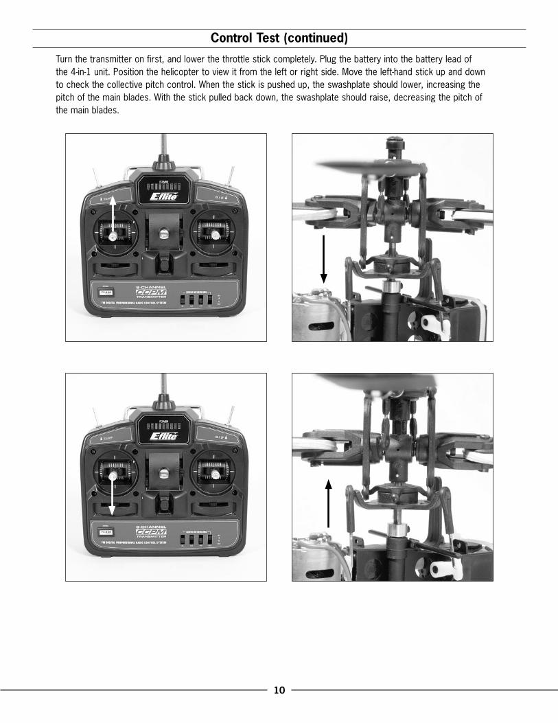
Control Test (continued)
Turn the transmitter on first, and lower the throttle stick completely. Plug the battery into the battery lead of the 4-in-1 unit. Position the helicopter to view it from the left or right side. Move the left-hand stick up and down to check the collective pitch control. When the stick is pushed up, the swashplate should lower, increasing the pitch of the main blades. With the stick pulled back down, the swashplate should raise, decreasing the pitch of the main blades.
11
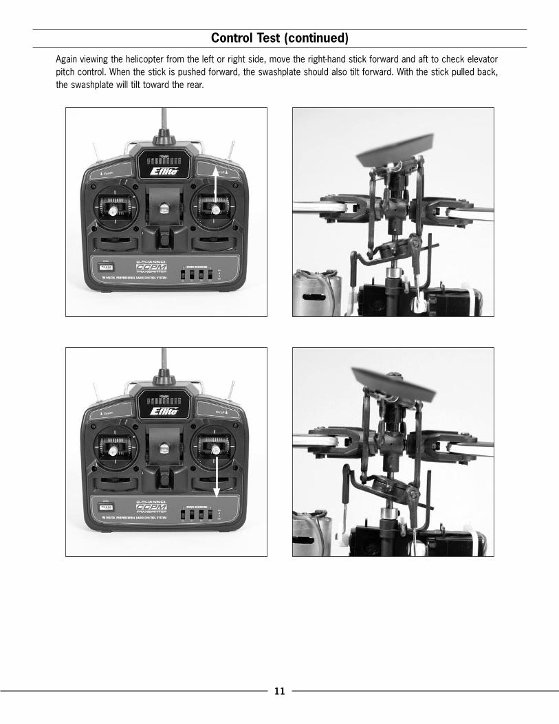
Control Test (continued)
Again viewing the helicopter from the left or right side, move the right-hand stick forward and aft to check elevator pitch control. When the stick is pushed forward, the swashplate should also tilt forward. With the stick pulled back, the swashplate will tilt toward the rear.

12
Control Test (continued)
Viewing the helicopter from the rear (tail boom toward you), move the right-hand stick left and right to check aileron roll control. When the stick is pushed to the left, the swashplate should also tilt left. With the stick pushed right, the swashplate will tilt to the right.

13
Control Test (continued)
If at any time during the test the controls do not respond properly, double-check the servo reversing switches on the transmitter. They should be positioned as follows:
AIL – NORELE – REVTHR – NORRUD – REV
If the controls still do not respond properly after ensuring the servo reversing switch positions are correct, you may also check the servo connections to the receiver of the 4-in-1 unit. These should be positioned as follows (when viewing the helicopter from behind):
Channel 1 – Right-hand rear “aileron” servoChannel 2 – Forward “elevator” servoChannel 6 – Left-hand rear “pitch” servo
Once you have confirmed proper reversing switch and servo connection locations, all controls should be functioning properly. If you do encounter any problems with your Blade™ CP responding properly to the transmitter, do not fly. Call Horizon’s Product Support staff at 1-877-504-0233.
If you have confirmed proper control operation of your Blade CP, reconnect the main and tail motor wires to the 4-in-1 unit, taking care to keep the proper polarity and location of each as they were before the test. The tail motor plug should be installed into the upper output slot of the 4-in-1 control unit with the positive lead to the top. The main motor plug should be installed into the lower output slot with the positive lead to the bottom. Please see the photo found on page 14 for reference.

14
4-in-1 Control Unit Description, Arming and Adjustment
The unique 4-in-1 Control Unit installed on your Blade CP is a lightweight combination of 6-channel FM receiver, main motor and tail motor mixer, main motor and tail motor electronic speed controls and piezo gyro. The 4-in-1 unit also contains a gyro gain trimmer pot, proportional tail rotor mix trimmer pot and status LED.
Below are tips for use and adjustment of your 4-in-1 unit to achieve the best performance of your Blade™ CP.
While each Blade CP model is test flown at the factory with adjustments made to both the gain and proportional trimmer pots, further adjustment to these trimmer pots may be required based on the type of battery used, or preference and flying style of the pilot. However, before any changes to the trimmer pots are made, test flights will need to be conducted. Use the following check list for your first and all subsequent flights:
• Each time before you fly you must always turn on the transmitter power first before connecting the flight battery to the 4-in-1 unit. Also be certain to fully extend the transmitter antenna before flight.
Note: The receiver antenna exiting the 4-in-1 unit will be coiled around the landing skid struts. We have made many successful flights indoors and out (some nearly out of sight) with the antenna coiled this way and did not experience any problems with performance of the radio system. If you are tempted to uncoil this antenna, please be sure to route it safely away from all moving parts and electronic items. Remember, due to the relatively small size of the Blade CP, you will not want to fly it very far away from yourself in order to keep proper orientation.
• Both the throttle stick and throttle trim need to be in their lowest possible position in order for the unit to arm. The “idle up” flight mode switch must also be in the “normal” position with the switch toggled toward the back of the transmitter for the unit to arm.
• If this is the first test flight, or a test flight following repairs, you will also want to center the rudder, aileron and elevator trims.
• Once confirming the transmitter has been turned on and has an adequate level of battery power as displayed by the LEDs at the top of the transmitter, it is now safe to plug the flight battery into the 4-in-1 unit.

15
4-in-1 Control Unit Description, Arming and Adjustment (continued)
• With power applied, the 4-in-1 unit status LED will blink red, then blink green. It is extremely important that during this time of calibration the helicopter is not moved or swayed in order for the gyro to properly initialize. If the helicopter was moved or swayed during this time, unplug the flight battery and repeat the initialization process.
• When the status LED becomes solid green, the unit is armed and ready for flight. Use caution as both the main and tail rotors will now run with throttle stick input. For safety, once the unit is armed, the main and tail motors will not run with the throttle stick and trim in their lowest positions. Do not advance the throttle stick until you are clear of the rotor blades and ready to fly.
• Once you have placed the helicopter in a safe place to fly (If this is your first test flight, the model should not be flown indoors unless it is in a very large area such as a gym. Until you have properly trimmed, adjusted and become familiar with the handling of the Blade CP, we suggest your first and any subsequent test flights be made outdoors in calm air), free of obstructions, and are clear of the rotor blades, you can safely power up the model. Advance the throttle stick slowly, noting the direction of the main and tail rotor blades as the rpms increase. The main rotor blades should spin clockwise when viewed from the top, with the tail rotor blades spinning counterclockwise when viewed from the right-hand side of the helicopter. If either set of rotor blades is operating in the wrong direction, unplug the battery, then simply reverse its motor wire plug polarity on the 4-in-1 unit.
• Once the tail rotor has begun to spin, and before lifting off, it is best to check that the tail rotor is responding properly to transmitter inputs. When inputting a slight amount of right rudder, the tail rotor rpms should increase, pushing the nose of the helicopter to the right. If you are on carpet, grass, or an otherwise uneven surface, be very careful not to allow the helicopter to catch the vertical tail support when testing the tail rotor control on the ground or during liftoff.
• If both rotor directions are correct, and the tail rotor is responding properly to rudder inputs, you can now lift your Blade CP into hover to check gyro gain and tail rotor proportional mix.
Note: The throttle trim can be used to adjust the throttle and collective pitch values for a given throttle stick position. For example, raising the throttle trim will allow the model to hover at a lower throttle stick position.
If you find your model will not lift off the ground with the throttle stick in the highest position, increasing the throttle trim will add collective pitch (You can also increase the pitch of the blades by adjusting the Pitch Control Links. See the “Throttle and Pitch Curve Adjustments” section on page 19 of this manual for more information).
Note: While the 4-in-1 control unit main motor and tail motor ESCs are readily capable of handling all in-flight power loads, and even brief momentary bursts beyond these typical loads, they can be damaged if excessive amounts of current are pulled through them for an extended period of time. This period of time may vary depending on the actual motor, pinion, and battery pack used, so it is best to keep any momentary overloads as short as possible in order to prevent damage to the 4-in-1 ESCs.
In the event of a crash, regardless of how minor or major, you MUST throttle back both the main and tail motors as quickly as possible. If a crash occurs when flying in Normal Mode (with the throttle trim increased any amount beyond the lowest setting), you will need to lower the throttle/collective stick AND throttle/collective trim immediately to prevent damage to the ESCs. If a crash occurs when flying in the Idle Up flight mode, you will need to switch back to Normal Mode while also lowering the throttle/collective stick and trim immediately to prevent damage to the ESCs.

16
Tail Rotor Proportional Mix Trimmer Pot Description and Adjustment
After establishing a stable hover, you will first want to adjust the tail rotor proportional mixing. The “proportional” trimmer pot adjusts the amount of tail motor to main motor mixing.
In hover, with the rudder trim centered and no rudder input, note which direction the nose of the helicopter is trying to spin. If the nose of the helicopter is spinning to the left, you will want to increase the amount of tail motor to main motor mixing. By turning the “proportional” trimmer pot clockwise (+), you increase the tail motor/rotor rpm for a given main motor/rotor rpm. This increase in tail motor/rotor rpm will help to push the nose of the helicopter to the right when in hover.
If the nose of the helicopter is trying to spin to the right in hover, decrease the tail rotor proportional mix by turning the “proportional” trimmer pot counterclockwise (-).
Note: You must always power down the helicopter before making adjustments to the proportional mix trimmer pot. Any changes made to this trimmer pot will not take effect until the 4-in-1 unit is initialized and re-armed.
As the battery output voltage decreases throughout the flight, it may be necessary to make small trim adjustments to the rudder in order to keep the nose of the helicopter straight. More experienced pilots may also choose to adjust the proportional mix to better hold the tail during aggressive climb outs and aerobatics rather than in hover only.
The amount of tail rotor proportional mix required may vary based on the type and performance of the chosen flight battery. When switching from 8-cell Ni-MH to 3-cell Li-Po for example, adjustments to the proportional mix will be required.
Proportional Trimmer Pot
17
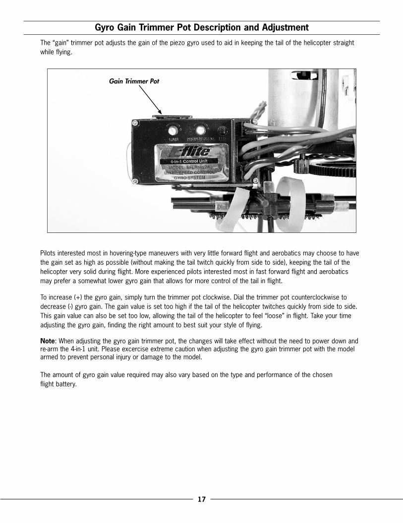
Gyro Gain Trimmer Pot Description and Adjustment
The “gain” trimmer pot adjusts the gain of the piezo gyro used to aid in keeping the tail of the helicopter straight while flying.
Pilots interested most in hovering-type maneuvers with very little forward flight and aerobatics may choose to have the gain set as high as possible (without making the tail twitch quickly from side to side), keeping the tail of the helicopter very solid during flight. More experienced pilots interested most in fast forward flight and aerobatics may prefer a somewhat lower gyro gain that allows for more control of the tail in flight.
To increase (+) the gyro gain, simply turn the trimmer pot clockwise. Dial the trimmer pot counterclockwise to decrease (-) gyro gain. The gain value is set too high if the tail of the helicopter twitches quickly from side to side. This gain value can also be set too low, allowing the tail of the helicopter to feel “loose” in flight. Take your time adjusting the gyro gain, finding the right amount to best suit your style of flying.
Note: When adjusting the gyro gain trimmer pot, the changes will take effect without the need to power down and re-arm the 4-in-1 unit. Please excercise extreme caution when adjusting the gyro gain trimmer pot with the model armed to prevent personal injury or damage to the model.
The amount of gyro gain value required may also vary based on the type and performance of the chosen flight battery.
Gain Trimmer Pot

18
Normal and Idle Up Flight Modes
The 6-channel FM transmitter included with your Blade™ CP features servo reversing and CCPM mixing, as well as an “idle up” flight mode switch. This switch allows the pilot to toggle between “normal” and “stunt” (aerobatic) flight modes during flight.
With the switch toggled toward the rear of the transmitter, the Blade CP will be flying in “normal mode.” In this flight mode, the throttle curve is linear from 0% to 100%, with a pitch range of 0 degrees to +10 degrees. (See Page 20 for additional data and graphics relating to the throttle and pitch curves preset for your Blade CP.) This is the preferred flight mode for general hovering and gentle forward flight.
Idle Up Switch

19
Normal and Idle Up Flight Modes (continued)
When the idle up switch is toggled toward the front of the transmitter, the Blade™ CP will now be flying in the “stunt (aerobatic)” flight mode. In this flight mode, the throttle curve is “V” shaped from 100% to 100% with 50% throttle at mid-stick, and a pitch range of –10 to +10 degrees (See page 20 for additional data and graphics relating to the throttle and pitch curves pre-set for your Blade CP). This flight mode is preferred for forward flight, aerobatics and inverted flying (requires symmetrical main blades).
Note: When in stunt mode, even with the throttle stick all the way down, the blades and motors will continue to spin. You must use the normal flight mode to safely turn off the motors. For safety, the 4-in-1 unit will not arm if the flight battery is plugged in and the flight mode switch is in the stunt position.
When switching between normal and stunt flight modes, it is best to do so in the air while hovering. The throttle and pitch curves of each flight mode have been optimized to transition smoothly around hover. Please be sure to never switch into stunt mode without having powered the main and tail motors up in normal mode first. The abrupt start could cause damage to the gears, motors or possibly even the 4-in-1 unit.
Throttle and Pitch Curve Adjustments
The throttle and pitch curves have already been set in the transmitter for both normal and stunt flight modes. These curves have been tested and optimized for the best overall performance in either flight mode.
Although the curves have already been factory set, minor changes to the pitch curves can be made by adjusting the Pitch Control Links. Lengthening both Pitch Control Links by equal amounts will increase the pitch of both blades. Shortening both Pitch Control Links by equal amounts will decrease the pitch of both blades
Pitch Control Link

20
Programmed Curves for the Normal Flight Mode
Right from the box, your Blade™ CP transmitter has been programmed for the following throttle and pitch curves in the normal flight mode:
��������
��������������
��� ���� ����
����
���
��
������
������
�����
��������������
��� ���� ����
����
��
����
������
�����
Programmed Curves for the Idle Up (Stunt) Flight Mode
Right from the box, your Blade CP transmitter has been programmed for the following throttle and pitch curves in the idle up (stunt) flight mode:
��������
��������������
��� ���� ����
����
���
��
������
������
�����
��������������
��� ���� ����
����
��
����
������
�����

21
Blade Tracking AdjustmentCaution: Be sure to maintain a safe distance from the helicopter (10–15 feet) when tracking the main rotor blades.
Blade tracking is a critical element to the flight performance of just about any helicopter, including the Blade™ CP. Main rotor blades that are out of track may cause vibration, instability, and loss of power due to increased drag. Although each Blade CP model is test flown with blades tracked at the factory, minor adjustments to blade tracking may be required after blade changes, repairs, or pitch curve adjustments.
For proper main rotor blade tracking and adjustments, please read the tips below:
• Before proceeding with the test flight of a new model or any model to which changes or repairs have been made, be certain that the main rotor blades have been properly installed and secured. The main blades should be tightened so they can pivot in the blade grip when moderate pressure is applied. Never allow the main blades to swing freely in their grips.
• Following the proper arming and start-up procedure previously listed in the “4-in-1 Control Unit Description, Arming and Adjustment” section, bring the main rotor blades of your Blade CP up to speed. You can check the blade tracking either on the ground or in the air at eye level. It might be a good idea to have an assistant on-hand to help sight the blades. Again, be certain to maintain a safe distance of 10–15 feet from the helicopter when checking the tracking of the main rotor blades.
• Once the main rotor blades have been brought up to speed, note which blade is running low and which blade is running high (by the colored tracking tape).
• You can then power the helicopter down and increase the pitch of the low blade by turning its Pitch Control Link end out one-half to one-full turn at a time. Or, you can decrease the pitch of the high blade by turning its Pitch Control Link end in one-half to one-full turn at a time.
The blade you choose to raise or lower when adjusting tracking will depend on the head speed of the model. For example, if the head speed in hover is low, you should lower the high blade.
Blades Out Of Track — Adjustment Necessary

22
Blade Tracking Adjustment (continued)
Typically, not much adjustment should be necessary to properly track the main rotor blades. If significant adjustments are required, be sure to double-check the length of both pitch control links (they should be close to the same length) and also check the blades for warps or twists. In most cases, you should be able to get both blades tracking perfectly in the same plane. However, due to the small size of the pitch links and threaded rods it may not always be possible to achieve absolutely perfect blade tracking. Don’t worry, as the helicopter should still perform well as long as the blade tracking is adjusted as closely as possible.
Flybar Paddle Tracking Adjustment
While main blade tracking is a critical element to flight performance, proper flybar paddle tracking and positioning is also important in maintaining proper control response and vibration-free operation.
For proper flybar paddle tracking, positioning and adjustments, please read the tips below:
• First, be certain that both flybar paddles are equally spaced from the ends of the paddle control frame.
• Next, be certain that both flybar paddles are parallel to the paddle control frame.
• If you have made certain that both flybar paddles are parallel to the paddle control frame, they should now be parallel to one another. If they are not, take your time making adjustments, ensuring that both flybar paddles are positioned parallel to one another and the paddle control frame.
• Once you have positioned the flybar paddles correctly following the steps above, be certain they are firmly secured using the included screws, washers and hex nuts.
Blades In Track — No Adjustment Necessary

23
2005 Official AMA National Model Aircraft Safety Code
GENERAL
1) I will not fly my model aircraft in sanctioned events, air shows or model flying demonstrations until it has been proven to be airworthy by having been previously, successfully flight tested.
2) I will not fly my model higher than approximately 400 feet within 3 miles of an airport without notifying the airport operator. I will give right-of-way and avoid flying in the proximity of full-scale aircraft. Where necessary, an observer shall be utilized to supervise flying to avoid having models fly in the proximity of full-scale aircraft.
3) Where established, I will abide by the safety rules for the flying site I use, and I will not willfully or deliberately fly my models in a careless, reckless and/or dangerous manner.
4) The maximum takeoff weight of a model is 55 pounds, except models flown under Experimental Aircraft rules.
5) I will not fly my model unless it is identified with my name and address or AMA number on or in the model. (This does not apply to models while being flown indoors.)
6) I will not operate models with metal-bladed propellers or with gaseous boosts, in which gases other than air enter their internal combustion engine(s); nor will I operate models with extremely hazardous fuels such as those containing tetranitromethane or hydrazine.
RADIO CONTROL
1) I will have completed a successful radio equipment ground range check before the first flight of a new or repaired model.
2) I will not fly my model aircraft in the presence of spectators until I become a qualified flier, unless assisted by an experienced helper.
3) At all flying sites a straight or curved line(s) must be established in front of which all flying takes place with the other side for spectators. Only personnel involved with flying the aircraft are allowed at or in front of the flight line. Intentional flying behind the flight line is prohibited.
4) I will operate my model using only radio control frequencies currently allowed by the Federal Communications Commission. (Only properly licensed Amateurs are authorized to operate equipment on Amateur Band frequencies.)
5) Flying sites separated by three miles or more are considered safe from site-to site interference, even when both sites use the same frequencies. Any circumstances under three miles separation require a frequency management arrangement, which may be either an allocation of specific frequencies for each site or testing to determine that freedom from interference exists. Allocation plans or interference test reports shall be signed by the parties involved and provided to AMA Headquarters. Documents of agreement and reports may exist between (1) two or more AMA Chartered Clubs, (2) AMA clubs and individual AMA members not associated with AMA Clubs, or (3) two or more individual AMA members.
6) For Combat, distance between combat engagement line and spectator line will be 500 feet per cubic inch of engine displacement. (Example: .40 engine = 200 feet.); electric motors will be based on equivalent combustion engine size. Additional safety requirements will be per the RC Combat section of the current Competition Regulations.
7) At air shows or model flying demonstrations, a single straight line must be established, one side of which is for flying, with the other side for spectators.
8) With the exception of events flown under AMA Competition rules, after launch, except for pilots or helpers being used, no powered model may be flown closer than 25 feet to any person.
9) Under no circumstances may a pilot or other person touch a powered model in flight.
24
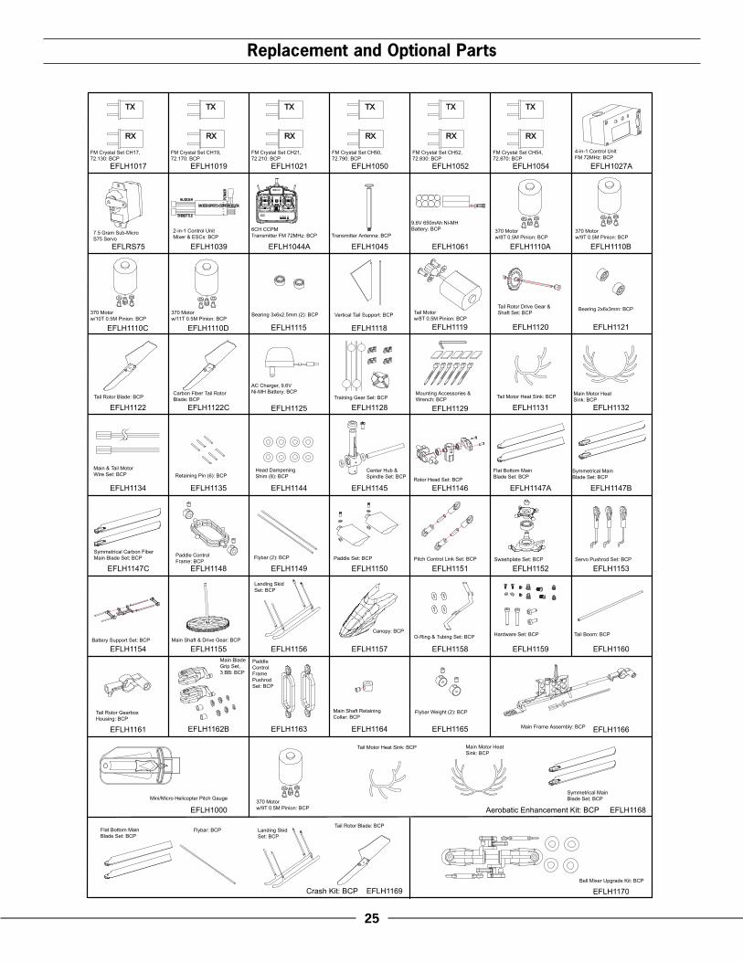
EFLH1100 . . . Blade CP RTF Electric Micro HeliEFLH1101 . . . Blade CP ARF Replacement AirframeEFLH1017 . . . FM Crystal Set CH17, 72.130: BCPEFLH1019 . . . FM Crystal Set CH19, 72.170: BCPEFLH1021 . . . FM Crystal Set CH21, 72.210: BCPEFLH1027A . . 4-in-1 Control Unit FM 72MHz: BCPEFLH1044A . . 6CH CCPM Transmitter FM 72MHz: BCPEFLH1045 . . . Transmitter Antenna: BCPEFLH1050 . . . FM Crystal Set CH50, 72.790: BCPEFLH1052 . . . FM Crystal Set CH52, 72.830: BCPEFLH1054 . . . FM Crystal Set CH54, 72.870: BCPEFLH1061 . . . 9.6V 650mAh Ni-MH Battery: BCPEFLRS75 . . . . 7.5 Gram Sub-Micro S75 ServoEFLRS751 . . . Gear Set: S75EFLRS752 . . . Case Set: S75EFLH1110C . . 370 Motor w/10T 0.5M Pinion: BCPEFLH1115 . . . Bearing 3x6x2.5mm (2): BCPEFLH1118 . . . Vertical Tail Support: BCPEFLH1119 . . . Tail Motor w/8T 0.5M Pinion: BCPEFLH1120 . . . Tail Rotor Drive Gear & Shaft Set: BCPEFLH1121 . . . Bearing 2x6x3mm (2): BCPEFLH1122 . . . Tail Rotor Blade: BCPEFLH1125 . . . AC Charger, 9.6V Ni-MH Battery: BCPEFLH1129 . . . Mounting Accessories & Wrench: BCPEFLH1134 . . . Main & Tail Motor Wire Set: BCP
Replacement Parts ListEFLH1135 . . . Retaining Pin (6): BCPEFLH1136 . . . Canopy Mount & Grommet Set: BCPEFLH1145 . . . Center Hub & Spindle Set: BCPEFLH1146 . . . Rotor Head Set: BCPEFLH1147A . . Flat Bottom Main Blade Set: BCPEFLH1148 . . . Paddle Control Frame: BCPEFLH1149 . . . Flybar (2): BCPEFLH1150 . . . Paddle Set: BCPEFLH1151 . . . Pitch Control Link Set: BCPEFLH1152 . . . Swashplate Set: BCPEFLH1153 . . . Servo Pushrod Set: BCPEFLH1154 . . . Battery Support Set: BCPEFLH1155 . . . Main Shaft & Drive Gear: BCPEFLH1156 . . . Landing Skid Set: BCPEFLH1157 . . . Canopy: BCPEFLH1158 . . . O-Ring Set: BCPEFLH1159 . . . Hardware Set: BCPEFLH1160 . . . Tail Boom: BCPEFLH1161 . . . Tail Rotor Gearbox Housing: BCPEFLH1162B . . Main Blade Grip Set, 3 BB: BCPEFLH1163 . . . Paddle Control Frame Pushrod Set: BCPEFLH1164 . . . Main Shaft Retaining Collar: BCPEFLH1165 . . . Flybar Weight (2): BCPEFLH1166 . . . Main Frame Assembly: BCPEFLH1169 . . . Crash Kit: BCP
Optional Parts List
EFLB1005 . . . 11.1V 860mAh 3-Cell Li-Po, JSTEFLB1015 . . . 11.1V 1200mAh 3-Cell Li-Po, JSTEFLC2020 . . . Pinnacle+ AC/DC 1-14C ChargerEFLC3005 . . . Celectra 1-3 Cell Li-Po ChargerEFLH1000 . . . Micro/Mini Helicopter Pitch GaugeEFLH1039 . . . 2-in-1 Control Unit Mixer & ESCs:BCPEFLH1110A . . 370 Motor w/8T 0.5M Pinion: BCPEFLH1110B . . 370 Motor w/9T 0.5M Pinion: BCPEFLH1110D . . 370 Motor w/11T 0.5M Pinion: BCPEFLH1122C . . Carbon Fiber Tail Rotor Blade: BCPEFLH1128 . . . Training Gear Set: BCPEFLH1131 . . . Tail Motor Heat Sink: BCPEFLH1132 . . . Main Motor Heat Sink: BCPEFLH1144 . . . Head Dampening Shim (8): BCPEFLH1147B . . Symmetrical Main Blade Set: BCPEFLH1147C . . Sym. Carbon Main Blade Set: BCPEFLH1168 . . . Aerobatic Enhancement Kit: BCPEFLH1170 . . . Bell Mixer Upgrade Kit: BCPTHP9003SJPL . 900mAh 3-Cell 11.1V Li-Po, JSTTHP13203SJPL 1320mAh 3-Cell 11.1V Li-Po, JST
Please see your favorite retailer or visit our web site (www.E-fliteRC.com) to find the latest in new replacement and option parts releases for your Blade™ CP.
Please see your favorite retailer or visit our web site (www.E-fliteRC.com) to find the latest in new replacement and option parts releases for your Blade™ CP.
25
Replacement and Optional Parts
EFLH1044AEFLRS75 EFLH1039
EFLH1027AEFLH1017
EFLH1000
EFLH1019 EFLH1021 EFLH1050 EFLH1052 EFLH1054
EFLH1125
EFLH1061EFLH1045 EFLH1110A EFLH1110B
EFLH1110C EFLH1110D EFLH1115 EFLH1118 EFLH1119 EFLH1120 EFLH1121
EFLH1122 EFLH1122C
EFLH1135
EFLH1128 EFLH1129 EFLH1131 EFLH1132
EFLH1134 EFLH1145EFLH1144 EFLH1146 EFLH1147B
EFLH1147C
EFLH1147A
EFLH1148 EFLH1149
EFLH1156
EFLH1150 EFLH1151 EFLH1152 EFLH1153
EFLH1154 EFLH1155
EFLH1164
EFLH1157 EFLH1158 EFLH1159
EFLH1161 EFLH1166
EFLH1170Crash Kit: BCP EFLH1169
Aerobatic Enhancement Kit: BCP EFLH1168
EFLH1160
EFLH1162B EFLH1163 EFLH1165
RX
TX
1 2JS
T
TX
RX
TXTXTXTX
RX RX RX RX
���
��
����������������������
������
��������
Tail Motorw/8T 0.5M Pinion: BCP
Tail Motor Heat Sink: BCP
Flat Bottom Main Blade Set: BCP
Flat Bottom Main Blade Set: BCP
Rotor Head Set: BCP
Symmetrical MainBlade Set: BCP
Symmetrical Carbon Fiber Main Blade Set: BCP
Mounting Accessories & Wrench: BCP
7.5 Gram Sub-Micro S75 Servo
Bearing 2x6x3mm: BCP
Tail Rotor Blade: BCPCarbon Fiber Tail Rotor Blade: BCP
Tail Rotor Blade: BCP
6CH CCPMTransmitter FM 72MHz: BCP Transmitter Antenna: BCP
FM Crystal Set CH17, 72.130: BCP
Mini/Micro Helicopter Pitch Gauge
FM Crystal Set CH19, 72.170: BCP
FM Crystal Set CH21, 72.210: BCP
FM Crystal Set CH50, 72.790: BCP
FM Crystal Set CH52, 72.830: BCP
FM Crystal Set CH54, 72.870: BCP
Paddle Control Frame: BCP
Main & Tail Motor Wire Set: BCP Retaining Pin (6): BCP
Head Dampening Shim (8): BCP
Main Motor Heat Sink: BCP
4-in-1 Control UnitFM 72MHz: BCP
Bearing 3x6x2.5mm (2): BCP
AC Charger, 9.6V Ni-MH Battery: BCP
370 Motor w/9T 0.5M Pinion: BCP
370 Motor w/9T 0.5M Pinion: BCP
370 Motor w/10T 0.5M Pinion: BCP
370 Motor w/11T 0.5M Pinion: BCP
370 Motor w/8T 0.5M Pinion: BCP
Center Hub & Spindle Set: BCP
Training Gear Set: BCP
Tail Rotor Drive Gear &Shaft Set: BCP
2-in-1 Control Unit Mixer & ESCs: BCP
Vertical Tail Support: BCP
9.6V 650mAh Ni-MH Battery: BCP
Tail Boom: BCP
Tail Rotor Gearbox Housing: BCP
Hardware Set: BCPCanopy: BCP
PaddleControlFramePushrod Set: BCP
Main Shaft Retaining Collar: BCP
Main Frame Assembly: BCP
Servo Pushrod Set: BCPPitch Control Link Set: BCP Swashplate Set: BCP
Main Shaft & Drive Gear: BCPBattery Support Set: BCP
Flybar (2): BCP
Flybar: BCP
Landing Skid Set: BCP
Landing Skid Set: BCP
Main Blade Grip Set, 3 BB: BCP
Paddle Set: BCP
O-Ring & Tubing Set: BCP
Symmetrical MainBlade Set: BCP
Bell Mixer Upgrade Kit: BCP
Main Motor Heat Sink: BCP
Tail Motor Heat Sink: BCP
Flybar Weight (2): BCP

26
001 . . . .Flybar Paddle (2) . . . . . . . . . . . . . EFLH1150002 . . . .Nut (2) . . . . . . . . . . . . . . . . . . . . EFLH1150003 . . . .Flybar (1) . . . . . . . . . . . . . . . . . . EFLH1149004 . . . .Collar (2) . . . . . . . . . . . . . . . . . . EFLH1148005 . . . .Rotor Head Frame A (1) . . . . . . . . EFLH1146006 . . . .Pitch Control Link (4) . . . . . . . . . . EFLH1151007 . . . .Threaded Rod (2) . . . . . . . . . . . . EFLH1151008 . . . .Center Hub (1) . . . . . . . . . . . . . . EFLH1145009 . . . .Paddle Control Frame Pushrod (2) . EFLH1163010 . . . .Main Blade Hold-Down Plate A (2) EFLH1147A011 . . . .Flat Head Screw (2) . . . . . . . . . . . EFLH1147A012 . . . .Main Blade Hold-Down Plate B (2) EFLH1147A013 . . . .Socket Head Cap Screw (2) . . . . . EFLH1159014 . . . .Bearing 3×6×2.5mm (10) . . . . . . EFLH1115015 . . . .Step Washer (4) . . . . . . . . . . . . . EFLH1162B016 . . . .Spindle (1) . . . . . . . . . . . . . . . . . EFLH1145017 . . . .Bearing 7×13×4mm (1) . . . . . . . . EFLH1152018 . . . . Lower Swashplate (1) . . . . . . . . . . EFLH1152019 . . . .Set Screw (5) . . . . . . . . . . . . . . . EFLH1159020 . . . .Pinion Gear (1) . . . . . . . . . . . . . . EFLH1110C021 . . . .Sub-Micro Servo (3) . . . . . . . . . . . EFLRS75022 . . . .Main Frame (1) . . . . . . . . . . . . . . EFLH1166023 . . . .4-in-1 Control Unit (1) . . . . . . . . . EFLH1027A024 . . . .Silicone Tube Section (9) . . . . . . . EFLH1158025 . . . .Strut (4) . . . . . . . . . . . . . . . . . . . EFLH1156026 . . . .Main Motor Washer (2) . . . . . . . . EFLH1110C027 . . . .Main Motor Screw (2) . . . . . . . . . EFLH1110C028 . . . .Skid (2) . . . . . . . . . . . . . . . . . . . EFLH1156029 . . . .Cap Head Screw (1) . . . . . . . . . . EFLH1145030 . . . .Center Hub Cap (1) . . . . . . . . . . . EFLH1145031 . . . .Paddle Control Frame (1) . . . . . . . EFLH1148032 . . . .Cap Head Screw (4) . . . . . . . . . . EFLH1146033 . . . .Rotor Head Frame B (1) . . . . . . . . EFLH1146034 . . . .Rotor Head (1) . . . . . . . . . . . . . . EFLH1146
035 . . . .Retaining Pin (1) . . . . . . . . . . . . . EFLH1135036 . . . .Socket Head Cap Screw (2) . . . . . EFLH1159037 . . . .Main Blade Grip (2) . . . . . . . . . . EFLH1162B038 . . . .O-Ring (2) . . . . . . . . . . . . . . . . . EFLH1158040 . . . .Washer (4) . . . . . . . . . . . . . . . . . EFLH1162B041 . . . .Cap Head Screw (2) . . . . . . . . . . EFLH1150042 . . . .Main Blade (2) . . . . . . . . . . . . . . EFLH1147A043 . . . .Swashplate Ball (1) . . . . . . . . . . . EFLH1152044 . . . .Upper Swashplate (1) . . . . . . . . . EFLH1152045 . . . .Servo Pushrod Control Link (3) . . . EFLH1153046 . . . .Servo Pushrod Threaded Rod (3) . . EFLH1153047 . . . .Main Shaft Retaining Collar (1) . . . EFLH1164048 . . . .Battery Support (1) . . . . . . . . . . . EFLH1154049 . . . .Battery Pack (1) . . . . . . . . . . . . . . EFLH1061050 . . . .Main Shaft & Drive Gear (1) . . . . EFLH1155051 . . . .Battery Support Rod Joiner (2) . . . EFLH1154052 . . . .Battery Support Rod (2) . . . . . . . . EFLH1154053 . . . .Canopy Mount Rod (2) . . . . . . . . EFLH1136054 . . . .Canopy (1) . . . . . . . . . . . . . . . . . EFLH1157055 . . . .Canopy Mount Grommet (4) . . . . . EFLH1136056 . . . .Tail Boom (1) . . . . . . . . . . . . . . . EFLH1160057 . . . .Tail Rotor Blade (1) . . . . . . . . . . . EFLH1122058 . . . .Vertical Tail Support (1) . . . . . . . . EFLH1118059 . . . .Tail Rotor Drive Gear (1) . . . . . . . EFLH1120060 . . . .Tail Motor Washer (2) . . . . . . . . . EFLH1119061 . . . .Tail Rotor Gearbox Housing (1) . . . EFLH1161062 . . . .Bearing 2×6×3mm (2) . . . . . . . . . EFLH1121063 . . . .Tail Motor Pinion (1) . . . . . . . . . . EFLH1119064 . . . .Tail Motor (1) . . . . . . . . . . . . . . . EFLH1119065 . . . .Tail Rotor Shaft (1) . . . . . . . . . . . . EFLH1120066 . . . .Tail Rotor Shaft Stop (1) . . . . . . . . EFLH1120067 . . . .Main Motor (1) . . . . . . . . . . . . . . EFLH1110C068 . . . .Bearing Spacer (2) . . . . . . . . . . . EFLH1162B069 . . . .Flybar Weight Collar (2) . . . . . . . EFLH1165
Exploded View Parts Listing
Please see your favorite retailer or visit our web site (www.E-fliteRC.com) to find the latest in new replacement and option parts releases for your Blade™ CP.
Exploded View
Reference Number
Description (Quantity Required)
Included In Item Number
Exploded View
Reference Number
Description (Quantity Required)
Included In Item Number

27
Exploded View
032019
031
030
029
041
042
057
024
056
052
051
053
046
045
043
044
047
019018
017
009
008
007
010
011
006
005
004
003
002
001
013015
014068
016038
037
035034
040036
015
025
024
067
022
023
012
027
020
021
028
050
049
048
054
055
066
058065
061
063
062
032
060
059
064
033
026

7565.1
© 2005 Horizon Hobby, Inc. 4105 Fieldstone Road
Champaign, Illinois 61822 (877) 504-0233 www.E-fliteRC.com