SPECIFICATIONS FOR LCD MODULE - DEMA NO.38,Keya Road , Daya Township, Taichung County 42878, Taiwan,...
26
SPECIFICATIONS FOR LCD MODULE MODEL NO. BG12864A series VER.04 FOR MESSRS: ________________________________________________ ON DATE OF: ________________________________________________ APPROVED BY: ________________________________________________ BOLYMIN, INC. 5F, NO.38,Keya Road , Daya Township, Taichung County 42878, Taiwan, R.O.C. Web Site:http://www.bolymin.com.tw TEL:+886-4-25658689 FAX:+886-4-25658698 DEMA Electronic AG | Phone: +49 (0)89 28 69 41 0 | Fax: +49 (0)89 28 35 09 | Email: [email protected] | Web: http://www.dema.net
-
Upload
truongdieu -
Category
Documents
-
view
215 -
download
2
Transcript of SPECIFICATIONS FOR LCD MODULE - DEMA NO.38,Keya Road , Daya Township, Taichung County 42878, Taiwan,...

SPECIFICATIONS FOR LCD MODULE
MODEL NO. BG12864A series
VER.04 FOR MESSRS: ________________________________________________ ON DATE OF: ________________________________________________ APPROVED BY: ________________________________________________
BOLYMIN, INC. 5F, NO.38,Keya Road , Daya Township, Taichung County 42878, Taiwan, R.O.C.
Web Site:http://www.bolymin.com.tw TEL:+886-4-25658689 FAX:+886-4-25658698
DEMA Electronic AG | Phone: +49 (0)89 28 69 41 0 | Fax: +49 (0)89 28 35 09 | Email: [email protected] | Web: http://www.dema.net

BG12864Aseries VER04 - 2 -
History of Version
Version Contents Date Note
01 NEW VERSION 2003/3/21
SPEC.
02 To modify Thought hole dim.
2005/02/21
03 MODIFY BACKLIGHT INFORMATION 2008/02/23
04
Add Handling Instruction Update Electrical Characteristics、、、、 Quality Assurance
and Reliability Modify Backlight Information
2013/01/07
DEMA Electronic AG | Phone: +49 (0)89 28 69 41 0 | Fax: +49 (0)89 28 35 09 | Email: [email protected] | Web: http://www.dema.net

BG12864Aseries VER04 - 3 -
C O N T E N T S
1. Numbering System
2. Handling Instruction
3. General Specification
4. Absolute Maximum Rating
5. Electrical Characteristics
6. Optical Characteristics
7. Interface Pin Function
8. Power supply for LCD Module and LCD operating voltage adjustment
9. Backlight information
10. Quality Assurance
11. Reliability
12. Appendix (Drawing , IC controller data)
12-1 Drawing
12-2 IC controller data
12-2.1 Display Control Instruction
12-2.2 Timing characteristics
DEMA Electronic AG | Phone: +49 (0)89 28 69 41 0 | Fax: +49 (0)89 28 35 09 | Email: [email protected] | Web: http://www.dema.net

BG12864Aseries VER04 - 4 -
1. Numbering System B G 12864 A xxx
0 1 2 3 4 5 6 7 8 9
0 Brand Bolymin
1 Module Type C= character type G= graphic type P= TAB/TCP type
O= COG type F= COF type L=PLED/OLED
2 Format 2002=20 characters, 2 lines 12232= 122 x 32 dots
3 Version No. A type
4 LCD Color G=STN/gray Y=STN/yellow-green PLED/yellow-green C=color STN,OLED/RGB
B=STN/blue,OLED/blue F=FSTN T=TN
5 LCD Type R=positive/reflective P=positive/transflective
M=positive/transmissive N=negative/transmissive
6 Backlight type/color L=LED array/ yellow-green H=LED edge/white R=LED array/red G=LED edge/yellow-green F=RGB array I=RGB edge Q=LED edge/red N=No backlight
D=LED edge/blue E=EL/white B=EL/blue C=CCFL/white Y=LED Bottom/yellow O=LED array/orange K=LED edge/green A=LED edge/amber
7 CGRAM Font (applied only on character type)
J=English/Japanese Font E=English/European Font G=Chinese(simple) F=Chinese(traditional)
C=English/Cyrillic Font H=English/Hebrew Font A=English/Arabic Font
8 View Angle/ Operating Temperature
B=Bottom/Normal Temperature H=Bottom/Wide Temperature U=Bottom/Ultra wide Temperature
T=Top/Normal Temperature W=Top/Wide Temperature C=9H/Normal Temperature E=Top/ultra wide temperature
9 Special Code 3=3 volt logic power supply n=negative voltage for LCD c=cable/connector 207d=AVANT IC
t=temperature compensation for LCD p=touch panel $=RoHS
DEMA Electronic AG | Phone: +49 (0)89 28 69 41 0 | Fax: +49 (0)89 28 35 09 | Email: [email protected] | Web: http://www.dema.net

BG12864Aseries VER04 - 5 -
2. Handling Instruction 2.1 Precaution in use of LCD Module
2.1.1. LCD panel is made of glass. Avoid excessive mechanical shock or applying strong pressure on the surface of display area.
2.1.2. The polarizer used on the display surface is easily scratched and damaged. Extreme care should be taken when handling. To clean dust or dirt off the display surface, wipe gently with cotton, or other soft material soaked with isopropyl alcohol, ethyl alcohol, do not use water, ketone or aromatics and never scrub hard.
2.1.3. Store the panel or module in a dark place where the temperature is 20℃±5℃ and the humidity is below 60% RH.
2.1.4. Keep LCD panels away from direct sunlight, also avoid them in high-temperature & high humidity environment for a long period.
2.1.5. Do not input any signal before power is turned on. 2.1.6. Avoid pressing on the metal bezel, otherwise the elastomer connector could be
deformed and lose contact, resulting in missing pixels and also cause rainbow on the display.
2.1.7. To control temperature and time of soldering is 320±10℃ and 3-5 sec. 2.1.8. EL manufactured from the organic film, and easily affected by temperature, humidity
and other environmental impact. Long-term placement in a place will cause low quality of the case. Therefore, unpack the cartons and start the production with the LCM within three months after the reception of them.
2.2 Static Electricity Precautions: 2.2.1. The LCD module contains a C-MOS LSI. People who operate the LCM should wear
ESD protection equipment to prevent ESD hurt on products. 2.2.2. Do not touch any of the conductive parts such as the LSI pads; the copper leads on the
PCB and the interface terminals with any parts of the human body. 2.2.3. Do not touch the connection terminals of the display with bare hand; it will cause
disconnection or defective insulation of terminals. 2.2.4. The modules should be kept in anti-static bags or trays for storage. 2.2.5. Only properly grounded soldering irons should be used. 2.2.6. If an electric screwdriver is used, it should be grounded and shielded to prevent sparks. 2.2.7. The normal static prevention measures should be observed for work clothes and
working benches. 2.2.8. Since dry air is inductive to static, a relative humidity of 50-60% is recommended.
2.3 Operation Precautions: 2.3.1. Since applied DC voltage causes electro-chemical reactions, which deteriorate the
display, the applied pulse waveform should be a symmetric waveform such that no DC component remains. Be sure to use the specified operating voltage.
2.3.2. Driving voltage should be kept within specified range; excess voltage will shorten display life.
2.3.3. An electrochemical reaction due to direct current causes LCD deterioration, Avoid the use of -Response time will be extremely delayed at lower temperature than the operating temperature range and on the other hand at higher temperature LCD's show dark color in them.
DEMA Electronic AG | Phone: +49 (0)89 28 69 41 0 | Fax: +49 (0)89 28 35 09 | Email: [email protected] | Web: http://www.dema.net

BG12864Aseries VER04 - 6 -
2.4 Safety: 2.4.1 If the LCD panel breaks, be careful not to get the liquid crystal to touch your skin.
If the liquid crystal touches your skin or clothes, please wash it off immediately by using soap and water.
2.5 WARRANTY POLICY BOLYMIN . WILL PROVIDE ONE-YEAR WARRANTY FOR THE PRODUCTS ONLY IF UNDER SPECIFICATION OPERATING CONDITIONS.
2.6 MTBF 2.6.1 .By specific test condition, MTBF based on 30 ℃normal operation temperature is
50,000hours. Estimator of L(10) is 5,268 hours. Remark: L(10) means accumulative defect rate equals 10% at the time of L(10).
2.6.2 Test Condition:
2.6.2.1 Supply Voltage for LCM: Typical Vdd
2.6.2.2 CC (Constant Current) mode and typical current is applied for LED.
2.6.2.3 Run-Patterns: by Bolymin's test program that has defined patterns and cyclic period.
2.6.2.4 Humidity: 60%RH
2.6.3 Test Criteria:
Loss of brightness at specific measured point: ≦ 50%
Loss of brightness at specific measured point: ≦ 20%
Display function at room temperature: Normal
Appearance: Normal
DEMA Electronic AG | Phone: +49 (0)89 28 69 41 0 | Fax: +49 (0)89 28 35 09 | Email: [email protected] | Web: http://www.dema.net

BG12864Aseries VER04 - 7 -
3.General Specification (1) Mechanical Dimension
Item Standard Value Unit
Number of dots 128×64 dots
Module dimension (L*W*H) 93.0*70.0*13.1(Max)-LED array/edge B/L
93.0*70.0*9.2(Max)- E/L or No B/L mm
View area 72(W)×40(H) mm
Active area 66.52(W)×33.24(H) mm
Dot size 0.48(W)×0.48(H) mm
Dot pitch 0.52(W)×0.52(H) mm
(2) Controller IC: NT7107/NT7108 or equivalent
(3) Temperature Range
Normal Wide
Operating 0 ~+50℃ -20 ~ +70℃
Storage -10 ~ +60℃ -30 ~ +80℃
4.Absolute Maximum Rating
Item Symbol Min Typ Max Unit
Operating Temperature TOP -20 - +70 ℃
Storage Temperature TST -30 - +80 ℃
Input Voltage VI 0 - VCC V
Supply Voltage For Logic VCC 0 - 6.7 V
Supply Voltage For LCD VCC-VLCD 0 - 16.7 V
Supply Voltage For LCD VOUT - - -5 V
DEMA Electronic AG | Phone: +49 (0)89 28 69 41 0 | Fax: +49 (0)89 28 35 09 | Email: [email protected] | Web: http://www.dema.net

BG12864Aseries VER04 - 8 -
5.Electrical Characteristics
Item Symbol Condition Min. Typ. Max. Unit
Supply Voltage For Logic VDD-VSS - 4.5 5.0 5.5 V
Supply Voltage For LCD VDD-V0 Ta=25℃ - 8.8 - V
Input High Vol V IH - 0.7VDD - VDD V
Input Low Vol V IL - 0 - 0.3VDD V
Output High Vol VOH - 2.4 - - V
Output Low Vol. VOL - - - 0.4 V
Supply Current IDD - - 18.0 - mA
6.Optical Characteristics a. STN
Item Symbol Condition Min. Typ. Max. Unit
View Angle (V)θ CR≧2 10 - 45 deg
(H)φ CR≧2 -30 - 30 deg
Contrast Ratio CR - - 3 - -
Response Time 25℃ T rise - - 200 350 ms
T fall - - 250 400 ms
DEMA Electronic AG | Phone: +49 (0)89 28 69 41 0 | Fax: +49 (0)89 28 35 09 | Email: [email protected] | Web: http://www.dema.net

BG12864Aseries VER04 - 9 -
b.FSTN
Item Symbol Condition Min. Typ. Max. Unit
View Angle (V)θ CR≧3 10 60 deg
(H)φ CR≧3 -45 45 deg
Contrast Ratio CR - 5 -
Response Time
25℃
T rise - 200 400 ms
T fall - 250 400 ms
3H
(θ=0°)
12H
6H
9H
θ θ
φ φ
DEMA Electronic AG | Phone: +49 (0)89 28 69 41 0 | Fax: +49 (0)89 28 35 09 | Email: [email protected] | Web: http://www.dema.net

BG12864Aseries VER04 - 10 -
B1
B1
B2
B2
VOP
VOP
Driving Voltage(V)
Driving Voltage(V)
Brightness(%)
Brightness(%)
Contrast Ratio=SingalSelect In Brightness
SingalSelect -NonIn Brightness
B1: Brightness In Select Signal B2: Brightness In Non-Select Signal
Positive Type
Negative Type
Non-Select Signal Select Signal
100% 90%
10%
100%
Tr Tf
Rise Time Fall Time Time(ms)
Brightness(%)
DEMA Electronic AG | Phone: +49 (0)89 28 69 41 0 | Fax: +49 (0)89 28 35 09 | Email: [email protected] | Web: http://www.dema.net

BG12864Aseries VER04 - 11 -
7.Interface Pin Function
Pin No. Symbol Level Description
1 Vss 0V Ground
2 Vdd 5.0V Supply voltage for logic
3 VO (Variable) Operating voltage for LCD
4 D/I H/L H: Data , L: Instruction
5 R/W H/L H: Read(MPU←Module) , L :Write(MPU→Module)
6 E H Enable signal
7 DB0 H/L Data bus line
8 DB1 H/L Data bus line
9 DB2 H/L Data bus line
10 DB3 H/L Data bus line
11 DB4 H/L Data bus line
12 DB5 H/L Data bus line
13 DB6 H/L Data bus line
14 DB7 H/L Data bus line
15 CS1 L Chip Select for IC1
16 CS2 L Chip Select for IC2
17 /RST L Reset signal
18 Vee Negative Voltage output –4.8V
19 A - Power supply for B/L ( + )
20 K - Power supply for B/L (GND)
DEMA Electronic AG | Phone: +49 (0)89 28 69 41 0 | Fax: +49 (0)89 28 35 09 | Email: [email protected] | Web: http://www.dema.net

BG12864Aseries VER04 - 12 -
8.Power supply for LCD Module and LCD operating voltage adjustment
*LCM operating on " DC 5V " input with built-in negative voltage
Vdd
Vss
Vo
Vee
LCM
built-in DC 5V
VR
N.V generator or Temp.
compensationcircuit -4.8V
*(Option) LCM operating on " DC 5V " input with external negative voltage
DC 5V
Negative voltexample -5v
VR
Vdd
Vss
Vo
LCM
Typ.:8.8V
*(Option) LCM operating on " DC 3V " input with external negative voltage
DC 3V
Negative volt -6v
VR
Vdd
Vss
Vo
LCM
DEMA Electronic AG | Phone: +49 (0)89 28 69 41 0 | Fax: +49 (0)89 28 35 09 | Email: [email protected] | Web: http://www.dema.net

BG12864Aseries VER04 - 13 -
*(Option) LCM operating on " DC 3V " input with built-in negative voltage
Vdd
Vss
Vo
Vee
LCM
built-in DC 3V
VRN.V generator
or Temp. compensation
circuit -6V
9.Backlight information (1) LED array / yellow-green
Parameter Symbol Min Typ Max Unit Test Condition
Supply Current ILED ─ 330 ─ mA V=4.1V
Supply Voltage V 4.0 4.1 4.4 V ILED=330mA
Reverse Voltage VR - - 5 V
Luminous Intensity IV 220 280 - cd/m2 ILED=330mA
Wave Length λp 568 - 573 nm ILED=330mA
Color Yellow Green
(2)LED edge/ White
Parameter Symbol Min Typ Max Unit Test Condition
Supply Current ILED - 60 - mA V=3.7V
Supply Voltage V 3.4 3.7 4.0 V ILED=60mA
Reverse Voltage VR - - 5 V -
Luminous Intensity IV 590 730 - cd/m2 ILED=60mA
CIE X 0.27 - 0.32
ILED=60mA Y 0.27 - 0.32
Color White
DEMA Electronic AG | Phone: +49 (0)89 28 69 41 0 | Fax: +49 (0)89 28 35 09 | Email: [email protected] | Web: http://www.dema.net

BG12864Aseries VER04 - 14 -
(3) EL white / blue Parameter Symbol Min Typ Max Unit Test Condition
Voltage Vrms -- 110 (AC) --
Frequency HZ -- 400 --
Brightness* cd/m2 48 50 --
110Vrms
400Hz
CIE
Chromaticity
Diagram
X -- 0.3019(white)
-- 0.330 (blue)
Y -- 0.3929(white)
-- 0.365 (blue)
Current Dissipation mA/cm2 -- 3.63 --
Power Dissipation mW/cm2 -- 71.71 --
Life time 5000 hrs
Color Blue , white
(2) Backlight driving methods
a. LED B/L drive from pin19 (LED+) pin20 (LED-) a.1 array (yellow-green)
a.2 edge/ White
DEMA Electronic AG | Phone: +49 (0)89 28 69 41 0 | Fax: +49 (0)89 28 35 09 | Email: [email protected] | Web: http://www.dema.net

BG12864Aseries VER04 - 15 -
b. E/L B/L driven from A.K cable directly
EL Panel Backlight
AC DC DC
INVERTERLCM
A
K+5V
+110V
→
DEMA Electronic AG | Phone: +49 (0)89 28 69 41 0 | Fax: +49 (0)89 28 35 09 | Email: [email protected] | Web: http://www.dema.net

BG12864Aseries VER04 - 16 -
10 Quality Assurance 10.1 Inspection conditions
1. The LCD shall be inspected under 20~40W white fluorescent light.
2. Checking Direction shall be in the 40 degree from perpendicular line of specimen surface.
3. Checker shall see over 30 cm. 4. Inspect about 5 seconds for each side.
10.2 Inspection Parameters
NO. Parameter Criteria
1 Black or White spots
Zone Dimension
Acceptable Number
Class Of Defects
Acceptable Level
D≦0.10 Disregard
Minor 0.65 0.10<D≦0.2 4
0.2<D≦0.3 2
0.3<D 0
D=(Long + Short)/2 Total defects should not exceed 5/module Defect that is located at outside of AA and doesn’t affect function is ignored.
2 Scratch,
Substances
Zone Acceptable
Number Class Of Defects
Acceptable Level X(mm) Y(mm)
- 0.05≧W Disregard
Minor 0.65 4.0≧L 0.05≧W 4
3.0≧L 0.1≧W 2
- 0.1<W 0
X: Length Y: Width Total defects should not exceed 5/module Defect that is located at outside of AA and doesn’t affect function is ignored.
DEMA Electronic AG | Phone: +49 (0)89 28 69 41 0 | Fax: +49 (0)89 28 35 09 | Email: [email protected] | Web: http://www.dema.net
BG12864Aseries VER04 - 17 -
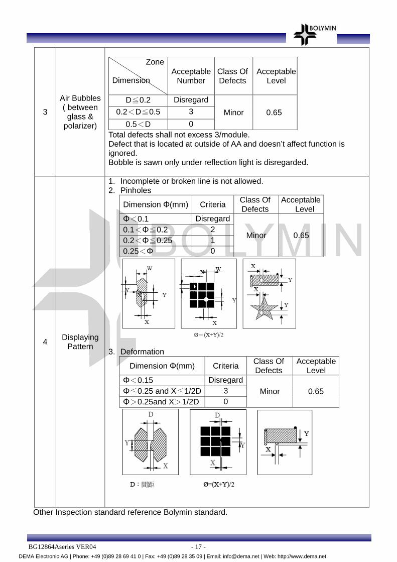
3
Air Bubbles ( between
glass & polarizer)
Zone Dimension
Acceptable Number
Class Of Defects
Acceptable Level
D≦0.2 Disregard
Minor 0.65 0.2<D≦0.5 3
0.5<D 0 Total defects shall not excess 3/module. Defect that is located at outside of AA and doesn’t affect function is ignored. Bobble is sawn only under reflection light is disregarded.
4 Displaying Pattern
1. Incomplete or broken line is not allowed. 2. Pinholes
Dimension Φ(mm) Criteria Class Of Defects
Acceptable Level
Φ<0.1 Disregard
Minor 0.65 0.1<Φ≦0.2 2 0.2<Φ≦0.25 1 0.25<Φ 0
3. Deformation
Dimension Φ(mm) Criteria Class Of Defects
Acceptable Level
Φ<0.15 Disregard Minor 0.65 Φ≦0.25 and X≦1/2D 3
Φ>0.25and X>1/2D 0
Other Inspection standard reference Bolymin standard.
DEMA Electronic AG | Phone: +49 (0)89 28 69 41 0 | Fax: +49 (0)89 28 35 09 | Email: [email protected] | Web: http://www.dema.net

BG12864Aseries VER04 - 18 -
11.Reliability ■Content of Reliability Test
Environmental Test
No Test Item Content of Test Test Condition Applicable
Standard
1 High Temperature storage
Endurance test applying the high storage temperature for a long time.
80℃
168 hrs ——
2 Low Temperature
storage
Endurance test applying the high storage temperature for a long time.
-30℃
168 hrs ——
3 High Temperature
Operation
Endurance test applying the electric stress (Voltage & Current) and the thermal stress to the element for a long time.
70℃
168 hrs ——
4 Low Temperature
Operation
Endurance test applying the electric stress under low temperature for a long time.
-20℃
168 hrs ——
5 Humidity Test Endurance test applying the high humidity storage for a long time.
40℃,90%RH
168 hrs ——
6 Temperature cycle
(Non-operation)
Endurance test applying the low and high temperature cycle.
-30℃ 80℃
30min 30min
1 cycle
-30℃/ 80℃
10 cycles ——
7 Vibration test Endurance test applying the vibration during transportation and using.
Total Fixed Amplitude:1.5mm
Vibration Frequency :10~55Hz
One cycle 60 seconds to 3 direction of X,Y,Z for each 15minutes
——
***Supply voltage for logic system=5V. Supply voltage for LCD system =Operating voltage at 25℃
DEMA Electronic AG | Phone: +49 (0)89 28 69 41 0 | Fax: +49 (0)89 28 35 09 | Email: [email protected] | Web: http://www.dema.net
BG12864Aseries VER04 - 19 -
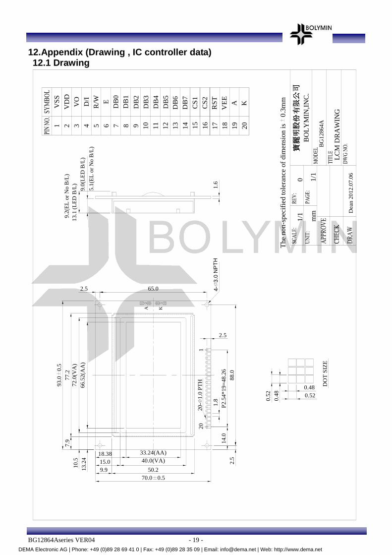
12.Appendix (Drawing , IC controller data) 12.1 Drawing
70.0 0.550.2
40.0(VA)33.24(AA)
88.0
20-
1.0
PT
H
P2.
54*1
9=48
.26
1.8
20
2.5
1
1.6
72.0
(VA
)
93.0
0.5
66.5
2(A
A)
10.5
7.9
13.
1 (L
ED
B/L
)
9.0(
LED
B/L
)13
.24
18.3815.09.9
14.0
2.5
2.5 65.0 4-3.
0 N
PT
H
DO
T S
IZE
0.48
0.52
0.480.52
BG
128
64A
0 1/1
mm
1/1
BO
LY
MIN
,INC
.股股 股股份份 份份
公公 公公
LCM
DR
AW
ING
Dea
n 20
12.0
7.06
Th
e no
n-s
pec
ifie
d to
lera
nce
of
dim
ens
ion
is
0.3
mm
12
14
13
VS
S1 7 11
108 94 6532
D/I
VO
VD
D
15
16
R/W E
DB
0
DB
1
DB
2
DB
3
DB
4
DB
5D
B6
DB
7
CS
1
CS
2
17
19
20
18
RS
T
VE
E
A K
77.2
A K
9.2(
EL
or N
o B
/L)
5.1
(EL
or N
o B
/L)
DEMA Electronic AG | Phone: +49 (0)89 28 69 41 0 | Fax: +49 (0)89 28 35 09 | Email: [email protected] | Web: http://www.dema.net

BG12864Aseries VER04 - 20 -
LED-White
70.0 0.550.2
40.0(VA)33.24(AA)
88.0
20-
1.0
PT
H
P2.
54*1
9=48
.26
1.8
20
2.5
1
1.6
72.0
(VA
)
93.0
0.5
66.
52(A
A)
10.5
7.9
13.2
4
18.3815.09.9
14.0
2.5
2.5 65.0 4-3.
0 N
PT
H
DO
T S
IZE
0.4
80.
52
0.480.52
BG
128
64A
0 1/1
mm
1/1
BO
LYM
IN,IN
C.
股股 股股份份 份份
公公 公公
LC
M D
RA
WIN
G
Dea
n 20
12.0
7.0
6
The
non
-spe
cifie
d to
lera
nce
of
dim
ens
ion
is
0.3m
m
12 1413
VS
S1 7 11108 94 6532
D/I
VO
VD
D
15 16
R/W E
DB
0D
B1
DB
2D
B3
DB
4D
B5
DB
6D
B7
CS
1C
S2
17 19 2018
RS
TV
EE
A K
77.2
13.
1 (
LED
B/L
)9
.0(L
ED
B/L
)
DEMA Electronic AG | Phone: +49 (0)89 28 69 41 0 | Fax: +49 (0)89 28 35 09 | Email: [email protected] | Web: http://www.dema.net

BG12864Aseries VER04 - 21 -
12.2 IC controller data 12.2.1 Display Control Instruction
The display control instructions control the internal state of theNT7108. Instruction is received from MPU to NT7108 for the display control. The following table shows various instructions.
Instruction D/I R/W DB7 DB6 DB5 DB4 DB3 DB2 DB1 DB0 Function
Display ON/OFF 0 0 0 0 1 1 1 1 1 0/1
Controls the display on or off. Internal status and display RAM data are not affected.
0:OFF, 1:ON
Set Address 0 0 0 1 Y address (0~63) Sets the Y address in the Y address counter.
Set Page
(X address) 0 0 1 0 1 1 1 Page (0 ~7)
Sets the X address at the X address register.
Display Start Line 0 0 1 1 Display start line(0~63) Indicates the display data RAM displayed at the top of the screen.
Status Read 0 1
B
U
S
Y
0 ON/OFF
R
E
S
E
T
0 0 0 0
Read status.
BUSY 0:Ready
1:In operation
ON/OFF 0:Display ON
1:Display OFF
RESET 0:Normal
1:Reset
Write Display Data
1 0 Display Data
Writes data (DB0:7)into display data RAM. After writing instruction, Y address is increased by 1 automatically.
Read Display Data
1 1 Display Data Reads data (DB0:7) from display data RAM to the data bus.
DEMA Electronic AG | Phone: +49 (0)89 28 69 41 0 | Fax: +49 (0)89 28 35 09 | Email: [email protected] | Web: http://www.dema.net
BG12864Aseries VER04 - 22 -
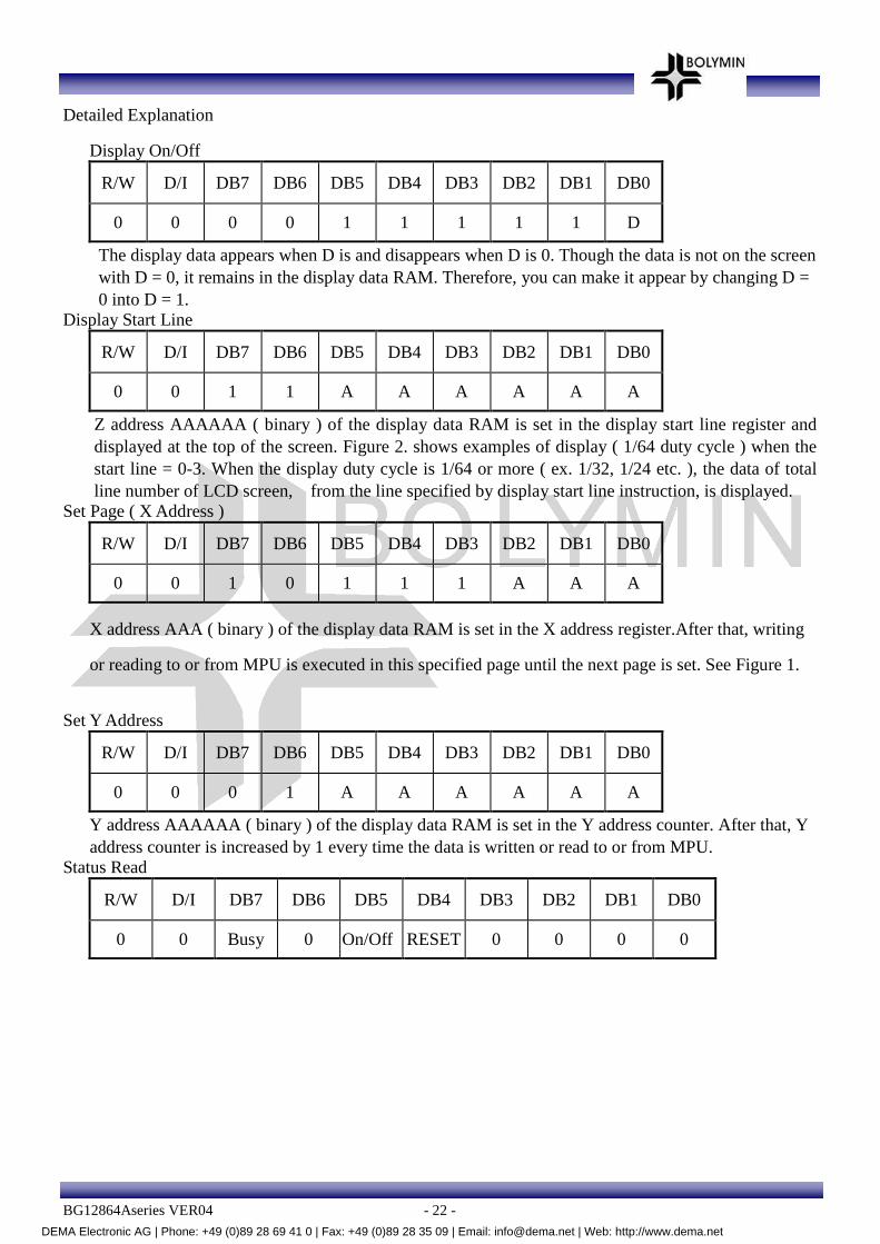
Detailed Explanation
Display On/Off
R/W D/I DB7 DB6 DB5 DB4 DB3 DB2 DB1 DB0
0 0 0 0 1 1 1 1 1 D
The display data appears when D is and disappears when D is 0. Though the data is not on the screen with D = 0, it remains in the display data RAM. Therefore, you can make it appear by changing D = 0 into D = 1.
Display Start Line
R/W D/I DB7 DB6 DB5 DB4 DB3 DB2 DB1 DB0
0 0 1 1 A A A A A A
Z address AAAAAA ( binary ) of the display data RAM is set in the display start line register and displayed at the top of the screen. Figure 2. shows examples of display ( 1/64 duty cycle ) when the start line = 0-3. When the display duty cycle is 1/64 or more ( ex. 1/32, 1/24 etc. ), the data of total line number of LCD screen, from the line specified by display start line instruction, is displayed.
Set Page ( X Address )
R/W D/I DB7 DB6 DB5 DB4 DB3 DB2 DB1 DB0
0 0 1 0 1 1 1 A A A
X address AAA ( binary ) of the display data RAM is set in the X address register.After that, writing
or reading to or from MPU is executed in this specified page until the next page is set. See Figure 1.
Set Y Address
R/W D/I DB7 DB6 DB5 DB4 DB3 DB2 DB1 DB0
0 0 0 1 A A A A A A
Y address AAAAAA ( binary ) of the display data RAM is set in the Y address counter. After that, Y address counter is increased by 1 every time the data is written or read to or from MPU.
Status Read
R/W D/I DB7 DB6 DB5 DB4 DB3 DB2 DB1 DB0
0 0 Busy 0 On/Off RESET 0 0 0 0
DEMA Electronic AG | Phone: +49 (0)89 28 69 41 0 | Fax: +49 (0)89 28 35 09 | Email: [email protected] | Web: http://www.dema.net

BG12864Aseries VER04 - 23 -
•Busy When busy is 1, the LSI is executing internal operations. No instruction are accepted while busy is 1, so
you should make sure that busy is 0 before writing the next instruction.
•ON/OFF Shows the liquid crystal display condition: on condition or off condition. When on/off is 1, the display is in off condition. When on/off is 0, the display is in on condition.
•RESET RESET = 1 shows that the system system is being initialized. In this condition, no instructions except status
read can be accepted. RESET = 0 shows that initializing has system is in the usual operation condition.
Write Display Data
R/W D/I DB7 DB6 DB5 DB4 DB3 DB2 DB1 DB0
0 0 D D D D D D D D
Writes 8-bit data DDDDDDDD ( binary ) into the display data RAM. The Y address is increased by 1 automatically.
Read Display Data
R/W D/I DB7 DB6 DB5 DB4 DB3 DB2 DB1 DB0
0 0 D D D D 1 D D D
Reads out 8-bit data DDDDDDDD (binary) from the display data RAM. Then Y address is increased by 1 automatically.
DEMA Electronic AG | Phone: +49 (0)89 28 69 41 0 | Fax: +49 (0)89 28 35 09 | Email: [email protected] | Web: http://www.dema.net

BG12864Aseries VER04 - 24 -
One dummy read is necessary right after the address setting. For details, refer to the explanation of output register in “Function of Each Block”.
Figure 1
0 1 2 61 62 63
D B 0toD B 7
toD B 7
D B 0
D B 7
D B 0to
toD B 7
D B 0
X = 0
X = 1
X = 6
X = 7
Y A dd ress
page 0
page 1
page 6
page 7
DEMA Electronic AG | Phone: +49 (0)89 28 69 41 0 | Fax: +49 (0)89 28 35 09 | Email: [email protected] | Web: http://www.dema.net

BG12864Aseries VER04 - 25 -
Figure 2
Start line = 0
COM 6
COM 64
COM 61COM 62COM 63
COM 60
COM 9COM 8COM 7
COM 2
COM 5COM 4COM 3
COM 1
COM 6
Start line = 1
COM 64
COM 61COM 62COM 63
COM 60
COM 9COM 8COM 7
COM 2
COM 5COM 4COM 3
COM 1
COM 6
Start line = 3
COM 64
COM 61COM 62COM 63
COM 60
COM 9COM 8COM 7
COM 2
COM 5COM 4COM 3
COM 1 COM 1
COM 3COM 4COM 5
COM 2
COM 7COM 8COM 9
COM 60
COM 63COM 62COM 61
COM 64
COM 6
Start line = 4
DEMA Electronic AG | Phone: +49 (0)89 28 69 41 0 | Fax: +49 (0)89 28 35 09 | Email: [email protected] | Web: http://www.dema.net

BG12864Aseries VER04 - 26 -
12.2.2 Timing characteristics
DEMA Electronic AG | Phone: +49 (0)89 28 69 41 0 | Fax: +49 (0)89 28 35 09 | Email: [email protected] | Web: http://www.dema.net