SPECIFICATIONS 1209 - D.N. Higgins
125
SPECIFICATIONS 100% SUBMITTAL FTEV 08‐1209 REPAIR STORM WATER DRAINAGE SYSTEM (Airfield Waiver) HURLBURT FIELD, FLORIDA July 5, 2011 7201 North 9 th Avenue, Suite 6 Pensacola, FL 32504 850-471-9005 [email protected]
Transcript of SPECIFICATIONS 1209 - D.N. Higgins

SPECIFICATIONS 100% SUBMITTAL
FTEV 08‐1209 REPAIR STORM WATER DRAINAGE SYSTEM
(Airfield Waiver) HURLBURT FIELD, FLORIDA
July 5, 2011
7201 North 9th Avenue, Suite 6 Pensacola, FL 32504
850-471-9005 [email protected]
Repair Storm Water Drainage System (Airfield Waiver) MS0109 Hurlburt Field, FL FTEV 08-1209
I-1
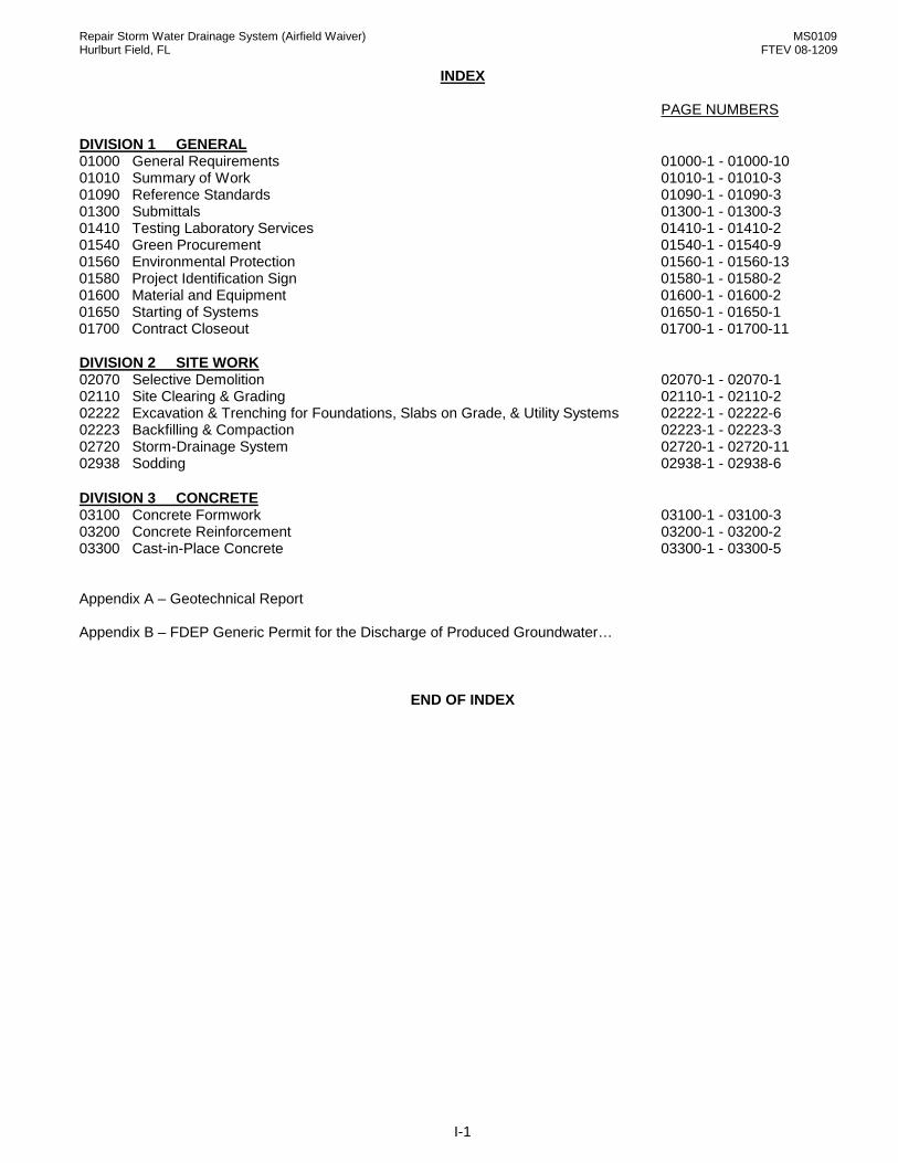
INDEX
PAGE NUMBERS
DIVISION 1 GENERAL 01000 General Requirements 01000-1 - 01000-10 01010 Summary of Work 01010-1 - 01010-3 01090 Reference Standards 01090-1 - 01090-3 01300 Submittals 01300-1 - 01300-3 01410 Testing Laboratory Services 01410-1 - 01410-2 01540 Green Procurement 01540-1 - 01540-9 01560 Environmental Protection 01560-1 - 01560-13 01580 Project Identification Sign 01580-1 - 01580-2 01600 Material and Equipment 01600-1 - 01600-2 01650 Starting of Systems 01650-1 - 01650-1 01700 Contract Closeout 01700-1 - 01700-11 DIVISION 2 SITE WORK 02070 Selective Demolition 02070-1 - 02070-1 02110 Site Clearing & Grading 02110-1 - 02110-2 02222 Excavation & Trenching for Foundations, Slabs on Grade, & Utility Systems 02222-1 - 02222-6 02223 Backfilling & Compaction 02223-1 - 02223-3 02720 Storm-Drainage System 02720-1 - 02720-11 02938 Sodding 02938-1 - 02938-6 DIVISION 3 CONCRETE 03100 Concrete Formwork 03100-1 - 03100-3 03200 Concrete Reinforcement 03200-1 - 03200-2 03300 Cast-in-Place Concrete 03300-1 - 03300-5 Appendix A – Geotechnical Report Appendix B – FDEP Generic Permit for the Discharge of Produced Groundwater…
END OF INDEX

MS1210
01000-1
SECTION 01000: GENERAL REQUIREMENTS PART 1 GENERAL 1.01 INTENT:
A. The intent of this project is to provide the Government with a fully complete and useable building meeting all the requirements for its intended use, constructed to high standards and the requirements of the Contract Documents. A fully complete and useable building is defined as one that is constructed to meet the aesthetic, functional and structural properties required by the drawings, specifications, amendments issued prior to receipt of bids/proposals, and modifications issued after award of the contract. All work shall be constructed to meet or exceed industry or government standards, whichever is more stringent. All construction shall be executed in a professional manner resulting in a finished product of highest quality. All materials, equipment, and other products used in the construction shall be new or approved recyclable materials from an approved source. All new work shall be maintained in a clean condition, and shall be installed plumb, square, true to line and grade, and shall conform to the stated dimensions, notes, schedules, etc. The work shall be properly secured, consistent in quality, fit and finish, and installation, etc.
1.02 APPLICABILITY:
A. This section of the specification is applicable to all sections that follow.
1.03 INTERPRETATION OF CONTRACT DOCUMENTS: A. Prospective bidders desiring further information, interpretation or clarification of the contract
documents shall forward a written request to the Contracting Officer. The Contracting Officer is the sole authority for interpretation of intent of work and for approval of quality of materials and workmanship. Failure to request the above shall not be the basis for a change order. DO NOT ASSUME THAT YOUR INTERPRETATION IS CORRECT.
1.04 CONFLICTS, DISCREPANCIES OR AMBIGUITIES: A. Prior to submittal of a bid or proposal by the prime/general contractor, it is expected that each
subcontractor, equipment and/or material supplier, and others associated with the project, shall have carefully examined as necessary, the drawings, specifications, and all addenda issued prior to the date of submission of the bid or proposal. Any and all conflicts, discrepancies or ambiguous language reasonably ascertainable from an inspection of the above and the project site that will affect the cost, quality, fit, finish, labor specified or required, equipment and/or materials specified or required, etc., necessary to fully complete the project and make it operational for it’s intended use, must immediately be brought to the attention of the prime/general contractor. The prime/general contractor must immediately notify the Contracting Officer in writing prior to submitting a bid or proposal and request written clarification of the conflict and/or discrepancy.
B. Conflicts, discrepancies and ambiguous language that are inconsistent with the intent as stated above
include but are not limited to: 1. Ambiguous notes or statements or drawings or details. 2. Conflicting information on the drawings and/or in the specifications. 3. Errors or inconsistencies in schedules. 4. Dimensional errors. 5. Incomplete notes or dimensions or schedules. 6. Extraneous notes, dimensions or schedules that conflict with the drawings or specifications. C. Conflicts, discrepancies or ambiguities brought to the attention of the Contracting Officer
AFTER award of contract WILL NOT be considered as a basis for a change in the work.
D. The intent of the above paragraphs is to increase the involvement of all persons associated with the project, particularly during the bid or proposal phase. Increased involvement during this phase will enhance the accuracy of the bid or proposal and reduce the potential for issuance of change orders during the construction phase.
1.05 DEFINITIONS: A. “Contract Documents": Contract Documents consist of the Contract, drawings and specifications, all
addenda issued prior to submission of the bid/proposal and all modifications and/or other directives issued
MS1210
01000-2
after the award/execution of the contract. The intent of the Contract Documents is to provide the Contractor with all items of work necessary for the proper execution and completion of the project. The items listed are complementary, what is required by one shall be as binding as if required by all. In the event of a conflict between the drawings and the specifications, the specifications shall take precedence over the drawings, unless otherwise noted on the drawings. The Contractor shall perform all work consistent with and reasonably inferable from the Contract Documents as necessary to produce the intended results.
B. “Government”: The government is the United States of America. The government is the owner of the
project. C. “Prime Contractor”: The Prime/General Contractor is the person or entity who is qualified, bonded and
insured, and who is responsible for preparing the bid/proposal and submitting it to the government. If the bid/proposal is accepted, the prime contractor will enter into a contract with the government to construct the work in accordance with the Contract Documents. The term “contractor” is used throughout the contract documents, and is synonymous with Prime/General Contractor, and means the contractor or the contractor’s authorized representative.
D. “Subcontractor”: A Subcontractor is a person or entity who prepares and submits a bid/proposal for a
portion of the work to the contractor for his use in preparing his bid/proposal. During the construction phase, the subcontractor has a direct contract with the contractor to perform a portion of the work.
E. “Material/Equipment Suppliers”: Material/equipment suppliers are person(s) or entities who prepare and submit a bid/proposal to the contractor for his use in preparing his bid/proposal. During the construction phase, the material equipment supplier has a direct contract with the contractor to provide certain materials or equipment to be incorporated into the work.
F. “Project”: The project is the total construction of the work to be performed under the contract documents
and may be the whole or part and which may include construction by the government.
G. “Work”: The term work means the providing of construction services required by the contract documents, and includes all labor, materials, equipment and other incidentals necessary to fulfill the contractor’s obligations. The work constitutes the whole project.
H. “Changes in the Work”: Changes in the work may be accomplished after award of contract without
invalidating the contract. Changes in the work shall be based upon a mutual agreement between the contractor and the government. Changes in the work shall be performed under applicable provisions of the contract documents unless otherwise provided for in the change. The time to complete the additional work shall also be a part of the agreement.
1.06 COORDINATION:
A. The prime contractor is responsible for the overall coordination of the project during the bid and or the proposal phase and the construction phase.
1. Coordinate bid and or the proposal phase to assure that all materials, labor, equipment, etc., to be used in the construction of the project and necessary for the completion of the prime contractor’s bid/proposal, as defined in 1.01 above, are included in the bids of the respective suppliers and/or subcontractors work, i.e., civil, architectural, plumbing, HVAC, or electrical.
2. Coordinate construction phase to assure efficient and orderly progression of the work. Coordination shall include, but is not limited to, periodic meetings between the contractor and subcontractors to coordinate the work of each trade one with the other, installation of one part of the work that is dependent on the installation of other components either before or after it's own installation, the materials and equipment needed to properly complete the work and ordering of those materials and equipment, preparation of schedules, layouts and phasing of the work as required to meet the government's stated needs, installation of and removal of temporary facilities, preparation and delivery of submittals including shop drawings, manufacturer’s product data, etc., scheduling of construction activities in the sequence required to obtain the best results, installation of different components within the allotted space to assure maximum accessibility for required maintenance or repair, periodic inspections of the work to assure compliance with the Contract Documents, visual inspections of the work to assure compliance with aesthetic requirements, maintenance and completion of all contract closeout documents including the coordination of supporting closeout documents by all subcontractors, maintenance and completion of Construction Data Worksheet, verification of new utility connections to each item of existing and new equipment, verify measurements of existing and

MS1210
01000-3
new work prior to installation of various components, proper storage of materials at the site particularly items requiring specific environmental conditions, protection of completed new work to minimize damage by other trades, cleaning, correction of punch list items of work after the final inspection, correction of warranty items during the warranty period, etc.
3. The prime contractor, each subcontractor, each equipment or material supplier and others who may be affiliated with the project are individually responsible for field verification of existing and new conditions that will affect their work, including the work of associated trades. Do not order, fabricate or install new items without field verification. Any discrepancy between the actual field dimension(s) and the size shown on the drawings, specifications, shop drawings, manufacturer’s product data, etc. must immediately be brought to the attention of the prime contractor, project inspector and Contracting Officer. The prime contractor shall request written direction from the Contracting Officer.
4. Prior to performing any Site work or work below grade, the Contractor must obtain a completed and signed copy of AF FORM 103, Base Civil Engineering Work Clearance Request.
5. Prior to bringing any lasers on Hurlburt Field, the contractor shall notify the Bio Environmental office 881-1822 and the Safety Office 884-7233.
B. Individual sections of this specification are taken from the Base Master Specification. Therefore, not all
products (materials, equipment, etc.) specified may be required to complete the construction of this project. In accordance with 1.05 above, the contractor, each subcontractor, equipment and/or material supplier, and others associated with the project, must carefully examine the drawings to determine which products are required to fully complete the work. See paragraph 1.04 Discrepancies.
1.07 CONSTRUCTION DATA WORKSHEET
A. The contractor must complete the checklist attached at the end of this section. 1. Section 1.a. General Data Required: The government will complete Category Code and Facility
number. 2. Section 1.b. Systems in Building: All.
1.08 METHODS:
A. The site shall be prepared, maintained, and operated by the contractor throughout the Work. Such preparation, maintenance, and operation include but are not limited to: 1. Preparation: Prevent damage to all existing construction, existing equipment and furnishings, existing
utilities and paved areas, and new items such as recently installed materials and equipment, new stored materials, trees/shrubs/landscape features identified to remain at the site, and privately owned vehicles in and around the work site. The contractor responsible for the damage will be held liable for the repair or replacement of the damaged item as directed by the Contracting Officer.
2. Safety and Security: Occupied and unoccupied facilities must be maintained in a safe manner to prevent the possibility of injury to the occupants and workmen. Upon completion of the days work, the contractor is responsible for securing the facility to prevent unlawful entry to the facility. If the interior of the facility or any equipment or furnishings are damaged due to the contractor's failure to properly secure the facility, the prime contractor and/or the subcontractor responsible for securing the facility will be held liable for the repair of the facility and replacement of the damaged equipment or furnishings as directed by the Contracting Officer.
3. Maintenance: Maintain the site in a neat and orderly manner to include daily trash/debris removal, stacking of material, control of surface drainage, mowing, and road sweeping.
4. Operation: Follow Occupational Safety and Health Administration requirements, US Army Corps of Engineers Safety and Health Requirements Manual EM 385-1-1, base law enforcement and base fire marshal requirements.
5. Trailers used for storage and/or temporary field offices shall be clean and well maintained and display only the name of the contractor or subcontractor.
1.09 CONSTRUCTION:
A. All work will be of professional quality. Intent of construction includes but is not limited to the following: 1. Utility connections shall be clean and complete. Contractor must request a utility outage from the
Contracting Officer no less than 3 working days prior to a scheduled outage for a single facility, and 14 days for outages affecting multiple facilities.
2. Backfilling and compaction will be performed so settling shall not occur. 3. All disturbed areas and all new graded areas shall be graded smooth and sodded. Seeding will be
permitted only if indicated on the drawings and/or approved by the Contracting Officer. Also, see other applicable sections(s) of the specification.
MS1210
01000-4
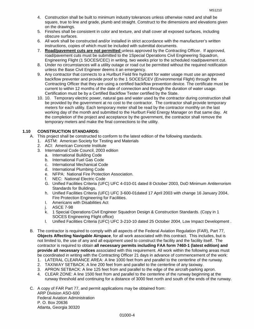
4. Construction shall be built to minimum industry tolerances unless otherwise noted and shall be square, true to line and grade, plumb and straight. Construct to the dimensions and elevations given on the drawings.
5. Finishes shall be consistent in color and texture, and shall cover all exposed surfaces, including obscure surfaces.
6. All work shall be constructed and/or installed in strict accordance with the manufacturer’s written instructions, copies of which must be included with submittal documents.
7. Road/pavement cuts are not permitted
8. Under no circumstances will a utility outage or road cut be permitted without the required notification unless the Base Civil Engineer deems it an emergency.
unless approved by the Contracting Officer. If approved, road/pavement cuts must be submitted to the 1Special Operations Civil Engineering Squadron, Engineering Flight (1 SOCES/CEC) in writing, two weeks prior to the scheduled road/pavement cut.
9. Any contractor that connects to a Hurlburt Field fire hydrant for water usage must use an approved backflow preventer and provide proof to the 1 SOCES/CEV (Environmental Flight) through the Contracting Officer that they are using a certified backflow prevention device. The certificate must be current to within 12 months of the date of connection and through the duration of water usage. Certification must be by a Certified Backflow Tester certified by the State.
10. 10. Temporary electric power, natural gas and water used by the contractor during construction shall be provided by the government at no cost to the contractor. The contractor shall provide temporary meters for each utility. Each temporary meter shall be read by the contractor monthly on the last working day of the month and submitted to the Hurlburt Field Energy Manager on that same day. At the completion of the project and acceptance by the government, the contractor shall remove the temporary meters and make the final connections to the utility.
1.10 CONSTRUCTION STANDARDS:
A. This project shall be constructed to conform to the latest edition of the following standards. 1. ASTM: American Society for Testing and Materials 2. ACI: American Concrete Institute 3. International Code Council, 2003 edition
a. International Building Code b. International Fuel Gas Code c. International Mechanical Code d. International Plumbing Code e. NFPA: National Fire Protection Association. f. NEC: National Electric Code G. Unified Facilities Criteria (UFC) UFC 4-010-01 dated 8 October 2003, DoD Minimum Antiterrorism
Standards for Buildings. h. Unified Facilities Criteria (UFC) UFC 3-600-01dated 17 April 2003 with change 16 January 2004,
Fire Protection Engineering for Facilities. I. Americans with Disabilities Act j. ASCE 7-98 k. 1 Special Operations
l. Unified Facilities Criteria (UFC) UFC 3-210-10 dated 25 October 2004, Low Impact Development .
Civil Engineer Squadron Design & Construction Standards. (Copy in 1 SOCES Engineering Flight office)
B. The contractor is required to comply with all aspects of the Federal Aviation Regulation (FAR), Part 77,
Objects Affecting Navigable Airspace, for all work associated with this contract. This includes, but is not limited to, the use of any and all equipment used to construct the facility and the facility itself. The contractor is required to obtain all necessary permits including FAA form 7460-1 (latest edition) and provide all necessary notices associated with this requirement. All work within the following areas must be coordinated in writing with the Contracting Officer 21 days in advance of commencement of the work: 1. LATERAL CLEARANCE AREA: A line 1000 feet from and parallel to the centerline of the runway.
2. TAXIWAY SETBACK: A line 200 feet from and parallel to the centerline of any taxiway. 3. APRON SETBACK: A line 125 feet from and parallel to the edge of the aircraft-parking apron. 4. CLEAR ZONE: A line 1500 feet from and parallel to the centerline of the runway beginning at the
runway threshold and continuing for a distance of 3000 feet north and south of the ends of the runway. C. A copy of FAR Part 77, and permit applications may be obtained from: ARP Division ASO-600 Federal Aviation Administration P. O. Box 20636 Atlanta, Georgia 30320

MS1210
01000-5
Phone 404-3056700 1.11 SUBSTITUTIONS: A. Throughout these specifications and/or on the drawings one or more "Trade Names" for a product may
be listed. When this occurs, all parties agree that the phrases: "or equal," "or approved equal," and "or equal as approved," follow each "Trade Name" listed. The contractor may submit substitute products, meeting the identified salient characteristics (physical and functional), to the Contracting Officer for review and approval. The term “Trade Names” includes Acceptable Manufacturers listed under PART 2 PRODUCTS of the specifications.
B. Approval Required:
1. The Contract is based on the standards of quality established in the Contract Documents. 2. All products proposed for use, including those specified by required attributes and performance shall
require approval by the Contracting Officer before being incorporated into the work. 3. Do not substitute
4. Refer to section 01600 for substitution submittal requirements.
materials, equipment, or methods unless such substitution has been specifically reviewed and approved for this Contract by the Contracting Officer.
C. Do not assume that materials, equipment or methods submitted, as a substitution, will be approved as equal.
The Contracting Officer is the sole interpreter of the Contract Documents.
1.12 ASBESTOS: A. See section 01560, Environmental Protection 1.13 LEAD BASED PAINT A. See section 01560, Environmental Protection 1.14 HAZARDOUS MATERIALS AND WASTE
A. See section 01560, Environmental Protection 1.15 CONTRACT PROGRESS REPORT A. Contractor progress reports shall be made in a timely manner and in accordance with the contract
documents. B. Contractor shall use the Contract Progress Report form at the end of this section. As indicated on the
form, all listed items of work may not be applicable to this project. Contractor shall submit completed form to include only those items of work applicable to this project.
C. Item 73, “Close-Out Documents” has been assigned a value of 3%. This amount will be withheld from final
payment until such time as all project record documents (including "As-Built" drawings), operation & maintenance data, spare parts & maintenance products, warranties, maintenance service, etc., have been turned over to the government. The contractor and subcontractors are advised to prepare these documents as the work progresses and not wait until the end of the project. These documents must be turned over to the government prior to the final inspection. The withholding of payment is not a penalty but is being done to assure compliance with specification Section 01700 CONTRACT CLOSEOUT.
1.16 CONTRACT PROGRESS SCHEDULE A. The contractor must provide a copy of the Contract Progress Schedule for review by the Contracting
Officer and the Construction Manager no later than 5 calendar days after the issuance of the Notice to Proceed. If disapproved, the contractor shall resubmit the revised Contract Progress Schedule within 2 days of the date of the disapproval. The Contract Progress Schedule must be approved within 10 days of the date of the disapproval. No construction work shall start without an approved Contract Progress Schedule.
B. The Contract Progress Schedule must be based on the data in the Contract Progress Report attached to
the end of the section. C. In order to satisfy the contract requirements that work commence within 10 days of Notice to Proceed, the
contractor may commence the submittal process in accordance with Section 01300. PART 2 NOT USED

MS1210
01000-6
PART 3 NOT USED
END OF SECTION

MS1210
01000-7
CONSTRUCTION DATA WORKSHEET
1. GENERAL DATA REQUIRED: A. PROJECT INFORMATION: Project No.: Contract No.: , Completion Date: _____ Category Code: ___________, Facility No.: ____________, Total Cost: ___________________
Liquidated Damages______________________________. Number of Floors: ______________ General Description: ___________________________________________________________________________ ___________________________________________________________________________ ___________________________________________________________________________ B. SYSTEMS IN BUILDING: Category Unit of Code Nomenclature Measure Amount Cost
Description (If Required)
880-211 Closed Head Auto Sprinkler HD/SF ____/___ _______ ______________________ 880-217 AFFF PA Sprink Sys HD/SF ____/ ___ _______ _________________________ 880-221 Auto Fire Detection System SF/EA ____/ ___ _______ _________________________ (Include Pull Stations) 880-232 Foam Fire System EA ________ _______ _________________________ 872-841 Security Alarm System EA ________ ________ _________________________ 811-147 Electric Emergency Power Generator KW ________ ________ _________________________ Storage Tank for Heating GA ________ ________ _________________________ Or Generator Fuel (Type Fuel) Storage Tank for Heating GA ________ ________ _________________________ 821-115 Heating Plt 750/3500 MB MB ________ ________ _________________________ 821-116 Heating Plt over 3500 MB MB ________ ________ _________________________ Storage Tank for Heating GA ________ ________ _________________________ 890-125 A/C Plt less 5 TN TN ________ ________ _________________________ 890-121 A/C Plt 5 to 25 TN TN ________ ________ _________________________ 826-122 A/C Plt 25 to 100 TN TN ________ ________ _________________________ 826-123 A/C Plt Over 100 TN TN ________ ________ _________________________ 890-126 A/C Window Units SF/TN ____/ ___ ________ _________________________ 824-464 Gas Mains LF ________ ________ _________________________ 844-368 Water Supply, Non-Potable KG ________ ________ _________________________ 852-261 Veh. Parking (Ops) SY ________ ________ _________________________ 852-262 Veh. Parking (Non-Org) SY ________ ________ _________________________ 132-133 Pad, Equip SY ________ ________ _________________________ 132-134 Ant. Spt Stru EA ________ ________ _________________________ 890-272 EMCS Field Equip EA ________ ________ _________________________ 812-223 Prim Dist Line OH LF ________ ________ _________________________ Transformers KV ________ ________ _________________________ 812-224 Sec Dist Line OH LF ________ ________ _________________________ 812-225 Prim Dist Line UG LF ________ ________ _________________________ 812-226 Sec Dist Line UG LF ________ ________ _________________________ 812-926 Exterior Lighting EA ________ ________ _________________________ (Street or Parking area Lights) 812-928 Traffic Lights EA ________ ________ _________________________ 831-157 Industrial Waste Fuel Spill Collection (Oil/Fuel) KG ________ ________ _________________________ 831-169 Sewage Septic Tank KG ________ ________ _________________________ (Facility # it supports) 832-266 Sanitary Sewer Main LF ________ ________ _________________________ 832-267 Sanitary Sewage Pump Station SF ________ ________ _________________________ 842-245 Water Dist Mains LF ________ ________ _________________________ 843-314 Fire Protection Water Main LF ________ ________ _________________________ 843-315 Fire Hydrants EA ________ ________ _________________________ 851-143 Curbs & Gutters SY ________ ________ _________________________ (Transition between Road & Parking lot)

MS1210
01000-8
C. RELATED FACILITIES: Category Code Nomenclature UM Amount Cost _
Description (If Reqd.)
851-145 Driveway SY ________ ________ __________________ 851-147 Road SY ________ ________ __________________ 871-183 Storm Drain Disposal LF ________ ________ __________________ 872-245 Fence, Boundary LF ________ ________ __________________ 872-247 Fence, Security LF ________ ________ __________________ 872-248 Fence, Interior LF ________ ________ __________________ 852-289 Sidewalk SY ________ ________ __________________ 890-269 Cathodic Protection Sys EA ________ ________ __________________ 890-181 Utility Line Duct-Elec LF ________ ________ __________________ 890-181 Utility Line Duct-Comm LF ________ ________ __________________ 890-158 Load and Unload Platform EA ________ ________ _________________ 832-255 Industrial Waste Main LF ________ ________ __________________ This checklist includes only the basic general construction category codes. More detailed category code listing information is available through the Real Property office, 884-6167.

MS1210
01000-9
CONTRACT PROGRESS REPORT
CONTRACTOR ADDRESS
REPORT
NO. PERIOD COVERED PROJECT NO. / TITLE
FROM TO
CONTRACT AMOUNT CONTRACT NO. COMPLETION DATE
$ NOTE: ALL ITEMS LISTED MAY NOT BE APPLICABLE TO THIS PROJECT. CONTRACTOR SHALL SUBMIT COMPLETED FORM TO INCLUDE ONLY THOSE ITEMS THAT ARE APPLICABLE TO THIS PROJECT.
LINE NO.
WORK ELEMENTS % OF TOTAL JOB
% COMPLETED THIS PERIOD
% COMPLETE CUMULATIVE
1 MOBILIZATION 2 DEMOLITION - ARCHITECTURAL 3 ASBESTOS / LEAD ABATEMENT 4 SITE PREPARATION 5 SITE UTILITIES 6 SITE IRRIGATION SYSTEM 7 SITE FINISH GRADING 8 SITE LANDSCAPING 9 ASPHALT PAVING / BASE 10 CONCRETE CURB / GUTTER 11 CONCRETE BUILDING SLAB / VAPOR BARRIER 12 CONCRETE WALKS / LANDINGS 13 CONCRETE FOOTINGS 14 CONCRETE BEAMS / COLUMNS 15 MASONRY FOUNDATIONS 16 MASONRY SCREENWALLS 17 MASONRY VENEER 18 STRUCTURAL STEEL 19 MISCELLANEOUS METALS / HANDRAILS / GRATES 20 WOOD AND PLASTICS 21 WALL INSULATION 22 ROOF INSULATION 23 EIFS 24 WINDOWS 25 EXTERIOR DOORS 26 STOREFRONT 27 OVERHEAD COILING DOORS 28 INTERIOR DOORS 29 HARDWARE 30 EXTERIOR METAL STUDWALLS / SHEATHING 31 INTERIOR METAL STUDWALLS / SHEATHING 32 PAINTING 33 WALL COVERING 34 TOILET ACCESSORIES 35 TOILET PARTITIONS / URINAL SCREEN 36 SIGNAGE 37 RAISED ACCESS FLOOR

MS1210
01000-10
LINE NO.
WORK ELEMENTS % OF TOTAL % THIS PERIOD % CUMULATIVE
38 PRE-ENGINEERED METAL BUILDING (PEMB)
39 PEMB ROOF / FASCIA 41 ELEVATORS / CONVEYING SYSTEMS 42 DEMOLITION - MECHANICAL / PLUMBING 43 NEW WATER / SEWER / NATURAL GAS SERVICE 44 PLUMBING ROUGH-IN UNDER SLAB 45 HVAC ROUGH-IN UNDER SLAB 46 PLUMBING ROUGH-IN ABOVE SLAB 47 PLUMBING FIXTURE / TRIM-OUT 48 COMPRESSED AIR SYSTEM 49 PIPE AND DUCT INSULATION 50 DUCTWORK 51 HYDRONIC PIPING 52 FIRE SUPPRESSION 53 HVAC EQUIPMENT 54 GRILLES / DIFFUSERS/ TRIM-OUT 55 CONTROLS 56 TEST AND BALANCE 57 DEMOLITION - ELECTRICAL 58 ELECTRIC SERVICE TEMPORARY 59 TRANSFORMER 60 PRIMARY OVERHEAD ELECTRIC SERVICE 61 PRIMARY UNDERGROUND ELECTRIC SERVICE 62 SECONDARY OH ELECTRIC SERVICE 63 SECONDARY UG ELECTRIC SERVICE 64 ELECTRIC ROUGH-IN 65 COMM / LAN ROUGH-IN 66 FIRE DETECTION ROUGH-IN 67 FIRE DETECTION EQUIPMENT / TRIM-OUT 68 COMM / LAN TRIM-OUT 69 ELECTRIC FIXTURES / TRIM-OUT 70 EXTERIOR LIGHTING 71 BONDING 72 DEMOBILIZATION 73 CLOSE-OUT DOCUMENTS 3%
TOTAL SCHEDULED AMOUNT THIS BILLING
TOTAL BID AMOUNT: SCHEDULED: ACTUAL:
INSPECTOR SIGNATURE: CONCUR NOT CONCUR (CIRCLE)
PROGRESS OR COMPLETION CERTIFICATE I HEREBY CERTIFY THAT THE CONTRACTOR HAS SATISFACTORILY COMPLETED THE INDICATED PERCENTAGE OF THE CONTRACT SPECIFICATIONS
SUBMITTED BY OR FOR CONTRACTOR: BASE CIVIL ENGINEER: TYPE OR PRINT NAME AND TITLE SIGNATURE DATE
REVIEWED BY OR FOR CONTRACTING OFFICER TYPE OR PRINT NAME AND TITLE SIGNATURE DATE

MS1210
01010-1
SECTION 01010: SUMMARY OF WORK PART 1 GENERAL 1.01 RELATED SPECIFICATION SECTIONS: A. Section 01000 – GENERAL REQUIREMENTS. 1.02 WORK INCLUDED: A. The contractor shall furnish all labor, materials, tools, supervision and equipment and perform all
operations necessary to accomplish all work complete in place, as shown on the drawings, specified herein, or as needed to construct FTEV 08-1209 Repair Storm Water Drainage System (Airfield Wavier).
1.03 JOB DESCRIPTION:
A. The work to be performed includes, but is not necessarily limited to, the following principal features: 1. Completion of NPDES NOI in accordance with Section 1560 Environmental Protection. 2. Installation of work zone traffic control devices in accordance with FDOT Design Standards for
Design, Construction, Maintenance, and Utility Operations on the State Highway System, Index 600, (Traffic Control Through Work Zones), as applicable for each phase of demolition and construction.
3. Installation and maintenance of erosion control measures. 4. Install temporary bypass and dewatering systems. Adjust and remove these systems as dictated by
work requirements. Remove temporary bypass system in its entirety upon completion of construction. 5. Install and maintain temporary measures, temporary berms, sheet pile, etc. as necessary for
protection of work-in-progress. Adjust and remove these systems as dictated by work requirements. 6. Complete earthwork and grading as necessary for construction. 7. Construct Concrete Junction Structure covering ditch from the endwall of the culverts underneath
Independence Roadway encapsulating the existing weir with provision for maintenance of unencumbered flow into existing stormwater treatment pond via a lateral weir in the side of the junction structure and with provision for connection of three corrugated metal arch pipes at the junction structure outlet.
8. Construct approximately 56 linear feet of 8’-10” X 6’-1” arch CMP (3 Required). 9. Construct 10:1 Miter Structure. 10. Complete fine grading and site stabilization. Stabilize all disturbed areas. 11. Complete final clean-up and remove all work zone signage.
1.04 CONTRACTOR USE OF SITE AND PREMISES A. Limit use of site to allow Owner visitation and inspection. B. The contractor and subcontractors are permitted to use existing utilities available at the site. Use is
subject to approval by the Contracting Officer. The 1 Special Operations Civil Engineering Squadron must approve all connections. Connection to existing water mains must utilize a backflow preventer, certified within the 12 months prior to use on base.
1.05 DISPOSAL A. All scrap materials and debris shall be disposed of in an on- site dumpster. When full, it shall be
emptied at a legally approved dumpsite off- base. It shall be the responsibility of the contractor to provide the dumpster and for the selection of the dumpsite. Provide Contracting Officer with name(s) of waste disposal company and approved dumpsite.
1.06 STORAGE AREA A. Contractor lay-down/materials storage site shall be as shown on the drawings or as approved by the
Contracting Officer. B. A minimum of a 6 foot high temporary visual barrier shall surround the area. C. The area must be maintained in a reasonably clean manner. All empty boxes, paper and trash must be
deposited in the on-site construction dumpster. 1.07 SAFETY A. The pertinent sections of the following publications are applicable to all work on this project. 1. U.S. Army Corps of Engineers: EM 385-1-1, Safety and Health Requirements Manual. 2. Air Force Instruction (AFI) 91-301. 3. AFOSH Standard 48.139. See Specification Section 01000 General Requirements paragraph
1.06.A.5.

MS1210
01010-2
1.08 HAUL ROUTE AND LITTER A. The Contractor shall utilize only the designated haul route for the project for access to and from the
site as shown on the Drawings. 1.09 USE OF BARGE AREA
A. Use of the barge off loading area is not allowed except as approved, in writing, by the Contracting Officer. Contractor must request usage of the barge site, in writing, to the Contracting Officer a minimum of 30 days prior to expected deliveries. Contractor must also submit a schedule of all deliveries. Under no circumstances should the contractor assume such requests will be approved. Contractor should plan to have materials delivered by other means.
B. If usage of the barge site is approved, the contractor must meet the following requirements: 1. Crane boom height cannot exceed eighty (80) feet from mean water elevation. 2. Crane boom must have a red flag and an operational blinking obstruction light. 3. Contractor will be responsible for surrounding water quality per the State of Florida Regulations.
Prior to delivery of any barge/crane or tug, contractor must install full-depth turbidity barriers both east and west of the site to extend beyond limits of off loading operations.
4. Off loading operations will be during daylight hours only. Operations will not start before 0700 (7:00 AM) and boom must be lowered to deck height by 1700 hours (5:00 PM) each day.
5. Contractor is required to provide the name and number of a responsible party, and contact information of the tug/crane operator at site to both of the following:
a. The Contracting Officer. b. Hurlburt Tower: Hurlburt Tower – 884-4795. (If tower cannot be contacted notify the Airfield
Manager – Mr Bob Baker, 884-4491, Cell 598-1543). 6. Upon notification of inclement weather, off loading operations must cease and the boom lowered
to deck height. Do not raise boom until cleared by the Hurlburt Tower. All barges and equipment must be secured. Upon notification of Hurcon conditions, the contractor must remove all barges, cranes, tugs, and associated equipment from the site. The government will not be responsible for any delays or costs associated to weather.
7. If notified to do so by the Contracting Officer or Hurlburt Tower, operations must cease and the boom lowered to deck height. Under no circumstances should the boom be raised until cleared by the notifying authority. The government will not be responsible for any associated delays or costs.
C. If these requirements cannot be met, the contractor is prohibited from using the barge site. Failure to adhere to these requirements during operations will result in immediate revocation of site use at no expense to the government. Site must be maintained per specifications and contractor will be responsible for any and all clean-up after operations.
PART 2 PRODUCTS (Not Used) PART 3 EXECUTIONS 3.01 INSPECTION A. The contractor shall accomplish work in an orderly progression of steps to satisfy the performance
requirements of this specification. 3.02 HOURS OF WORK A. The normal hours of a workday shall be between 7:00 A.M. and 4:00 P.M., Monday through Friday,
except holidays and observed holidays. The contractor may elect, at his option, to work hours other than normal duty hours if approved by the Contracting Officer. All work time, other than normal working days, shall be requested in writing, 3 days in advance.
3.03 PHOTOGRAPHS
A. The contractor will take before and after photographs of the work. "Before" photos will be submitted before the start of work. "After" photos will be submitted before the acceptance of the work. A minimum of 24 photos of each will be required. Photos must show exterior and interior areas of the building that are to receive the new work. The intent is to show the amount of change. Photos may be submitted by the Air Force for design and construction awards. All photos taken shall be in digital format and submitted on CD. Submit one copy of before and after photos.

MS1210
01010-3
3.04 QUALITY CONTROL A. The contractor shall establish and maintain quality control to assure compliance with Contract
Documents, and maintain records of his quality control for materials, equipment and construction operations.
3.05 CONSTRUCTION LAYOUT & VERIFICATION: A. The contractor shall employ a Florida Registered Land Surveyor to layout the building and other site
features in accordance with the drawings. Potential problems that will affect the site geometry shall immediately be brought to the attention of the Contracting Officer.
B. Horizontal and Vertical Control shall conform to Hurlburt Field Datum: Horizontal NAD-83; Vertical NAVD-
88. C. Upon completion of the project and prior to the submission of the "As-Built" drawings (See Section 01700
Contract Closeout), the contractor shall employ a Florida Registered Land Surveyor to perform the following Horizontal Control by use of Global Positioning Satellite (GPS) to sub-meter accuracy, and Vertical Control using the above datum.:
1. Location of building corners. 2. Buried water mains, sanitary and/or storm water sewers including all valves, cleanouts, horizontal
turns, etc. 3. Elevations at top of manhole(s), lift stations, storm water structures or similar above ground
structures. 4. Invert elevations of all manholes and stub-outs intended for future connections to the system. 3.06 WARRANTY INSPECTION
A. A warranty inspection will be held thirty (30) days prior to the expiration of the contractor’s one-year warranty. The inspection will be held at the project site. Those in attendance shall include the contractor, the Contracting Officer, the project inspector, and the occupant. The purpose of this inspection will be to identify current or re-occurring problems associated with the project and past warranty calls and corrective action taken to remedy them. The contractor shall contact the Contracting Officer to determine the date of the inspection. The Contracting Officer shall contact the appropriate government agencies and confirm the date the inspection is to take place.
B. A list of problems identified at the inspection will be provided to all those in attendance. All problems must
be corrected to the satisfaction of the government prior to the expiration of the warranty
END OF SECTION

MS0109
01090-1
SECTION 01090 REFERENCE STANDARDS
PART 1 - GENERAL
1.01 RELATED SPECIFICATION SECTIONS:
A. Section 01000 - GENERAL REQUIREMENTS
1.02 SECTION INCLUDES A. Applicability of Reference Standards.
B. Provision of Reference Standards at site.
C. Source and acronyms used for Reference Standards in Contract Documents.
1.03 APPLICABILITY OF REFERENCE STANDARDS
A. For products or workmanship specified by association, trade, or Federal Standards, comply with requirements of the standard, except when more rigid requirements are specified or are required by applicable codes.
B. The publications listed in the various specification sections form a part of the specification to the extent
referenced. The publications are referred to in the text by basic designation only.
C. Use the latest standard, except when a specific date is specified.
D. Disregard payment provisions contained in any portion of the referenced specifications and standards.
E. If the specified reference standard(s) conflicts with the Contract Documents, request clarification from the Contracting Officer before proceeding.
1.04 PROVISION OF REFERENCE STANDARDS AT SITE
A. When required by individual specifications sections, obtain a copy of the standard. Maintain a copy at the jobsite during submittals, planning, and progress of the specific work until completion.
1.05 ABBREVIATIONS & NAMES
A. Where acronyms or abbreviations are used in the specifications or other Contract Documents, they mean the recognized name of the trade association, standards-generating organization, and authority having jurisdiction or other entity applicable. Refer to “Encyclopedia of Associations” published by Gale Research Co., available in most libraries.
1.06 SOURCE FOR REFERENCE STANDARDS
AASHTO American Association of State Highway and Transportation Officials 444 N. Capital St., NW, Suite 249 Washington, DC 20001
ACI American Concrete Institute P.O. Box 19150 Detroit, MI 48219 ACPA American Concrete Pipe Association 8300 Boone Blvd., #400 Vienna, VA 22182 ANSI American National Standards Institute 11 West 42nd St. New York, NY 10036
ASNT American Society for Non-destructive Testing 4153 Arlingate Plaza Columbus, OH 43228-0518

MS0109
01090-2
ASTM American Society for Testing and Materials 1916 Race Street Philadelphia, PA 19103
AWS American Welding Society P.O. Box 351040 Miami, FL 33135
AWWA American Water Works Association 6666 West Quincy Denver, CO 80235
CFR Code of Federal Regulations Order from: Superintendent of Documents Government Printing Office Washington, DC 20402-9371
CRSI Concrete Reinforcing Steel Institute 933 No. Plum Grove Rd. Schaumburg, IL 60173-4758
CS United States Department of Commerce Standard Order from: National Technical Information Service 5285 Port Royal Rd. Springfield, VA 22161
FAA Federal Aviation Administration Department of Transportation Order from: Superintendent of Documents Government Printing Office Washington, DC 20402-9371 For documents offered at no cost, order from: Dept. of Transportation ATTN: M443.2 400 Seventh St., SW Washington, DC 20590
FS Federal Specifications Order from: Standardization Documents Order Desk Bldg 4, Section D 700 Robbins Ave. Philadelphia, PA 19111-5094
FTM-STD Federal Test Method Standards Order from: Standardization Documents Order Desk Bldg 4, Section D 700 Robbins Ave. Philadelphia, PA 19111-5094
MS Military Specifications (MILSPEC) Standardization Documents Order Desk Bldg 4, Section D 700 Robbins Ave. Philadelphia, PA 19111-5094
MSS Manufacturers’ Standardization Society of the Valve and Fittings Industry

MS0109
01090-3
127 Park St., NE Vienna, VA 22180
NBS National Bureau of Standards (U. S. Department of Commerce) Gaithersburg, MD 20234
OSHA Occupational Safety and Health Administration (U.S. Department of Labor) Order from: Superintendent of Documents Government Printing Office Washington, DC 20402-9371 PART 2 - PRODUCTS: NOT USED. PART 3 - EXECUTION: NOT USED.
END OF SECTION
MS0109
01300-1
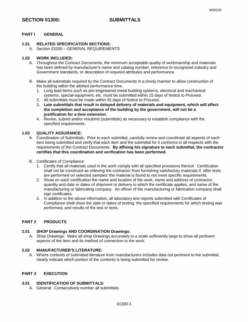
SECTION 01300: SUBMITTALS PART l GENERAL 1.01 RELATED SPECIFICATION SECTIONS: A. Section 01000 – GENERAL REQUIREMENTS 1.02 WORK INCLUDED:
A. Throughout the Contract Documents, the minimum acceptable quality of workmanship and materials has been defined by manufacturer's name and catalog number, reference to recognized industry and Government standards, or description of required attributes and performance.
B. Make all submittals required by the Contract Documents in a timely manner to allow construction of
the building within the allotted performance time. 1. Long lead items such as pre-engineered metal building systems, electrical and mechanical
systems, special equipment, etc. must be submitted within 15 days of Notice to Proceed. 2. All submittals must be made within 45 days of Notice to Proceed. 3. Late submittals that result in delayed delivery of materials and equipment, which will affect
the completion and acceptance of the building by the government, will not be a justification for a time extension.
4. Revise, submit and/or resubmit (submittals) as necessary to establish compliance with the specified requirements.
1.03 QUALITY ASSURANCE:
A. Coordination of Submittals: Prior to each submittal, carefully review and coordinate all aspects of each item being submitted and verify that each item and the submittal for it conforms in all respects with the requirements of the Contract Documents. By affixing his signature to each submittal, the contractor certifies that this coordination and verification has been performed.
B. Certificates of Compliance:
1. Certify that all materials used in the work comply with all specified provisions thereof. Certification shall not be construed as relieving the contractor from furnishing satisfactory materials if, after tests are performed on selected samples' the material is found to not meet specific requirements.
2. Show on each certification the name and location of the work, name and address of contractor, quantity and date or dates of shipment or delivery to which the certificate applies, and name of the manufacturing or fabricating company. An officer of the manufacturing or fabrication company shall sign certificates.
3. In addition to the above information, all laboratory test reports submitted with Certificates of Compliance shall show the date or dates of testing, the specified requirements for which testing was performed, and results of the test or tests.
PART 2 PRODUCTS 2.01 SHOP Drawings AND COORDINATION Drawings:
A. Shop Drawings: Make all shop Drawings accurately to a scale sufficiently large to show all pertinent aspects of the item and its method of connection to the work.
2.02 MANUFACTURER'S LITERATURE:
A. Where contents of submitted literature from manufacturers includes data not pertinent to the submittal, clearly indicate which portion of the contents is being submitted for review.
PART 3 EXECUTION 3.01 IDENTIFICATION OF SUBMITTALS:
A. General: Consecutively number all submittals.

MS0109
01300-2
B. Internal Identifications: On at least the first page of each copy of each submittal and elsewhere as required for positive identification, clearly indicate the submittal number in which the item was included.
C. Indicate FTEV Number, Project Title and Contract Number 3.02 COORDINATION OF SUBMITTALS:
A. General: Prior to submittal for approval, use all means necessary to fully coordinate all material including, but not necessarily limited to: 1. Determine and verify all interface conditions, catalog numbers and similar data. 2. Coordinate with other trades as required. 3. Clearly indicate all deviations from requirements of the Contract Documents.
B. Grouping of submittals: Unless otherwise specified, make all submittals in groups containing all
associated items to ensure that information is available for checking each item when it is received. Partial submittals will be rejected as not complying with the provisions of the Contract Documents and the contractor shall be strictly liable for all delays so occasioned.
C. Interior Finish Materials/Colors/Samples: All interior finish materials/colors/samples, includIng but not
limited to, flooring, base, paint/stain, wall coverings, acoustic ceiling/suspension system, acoustical treatment, window treatment, laminated plastic for base/wall cabinets/countertops, interior signage, etc., shall be submitted as a group (one submittal) to allow the government to review/approve/disapprove and select/coordinate the interior finish materials/colors prior to being incorporated into the work. Upon receipt of the government's approved selections, the contractor shall provide the government with actual samples of each item for the record, minimum size 4"x4", except laminate plastic chips shall be manufacturer's standard size.
D. Exterior Finish Materials/Colors/Samples: All exterior finish materials/colors/samples, including but not
limited to, brick, concrete masonry, exterior insulation finish system, stucco, paint/stain, roofing/flashing, exterior signage, pavers, windows, doors, etc., shall be submitted as a group (one submittal) to allow the government to review/approve/disapprove and /select/coordinate the exterior finish materials/colors prior to being incorporated into the work. Upon receipt of the government's approved selections, the contractor shall provide the government with actual samples of each item for the record, minimum size 4"x4".
3.03 SUBMITTAL APPROVAL:
A. General: Approval by the Contracting Officer shall not be construed as a complete check, but only that the general method of construction and detailing is satisfactory. Review and approval by government shall not relieve the contractor from responsibility for errors that may exist, or from liability for failure to comply with the intent of the Contract Documents.
B. Revisions After Approval: When a submittal has been approved, a re-submittal by the contractor for the
purpose of substitution of materials or equipment, will not be considered unless accompanied by an acceptable explanation as to why the substitution is necessary.
C. Unnecessary Submissions: When the contractor elects to provide the materials, equipment, etc., that
was used as the basis for the design and is the exact: Manufacture's name, catalog number, size, and finish as shown in the drawings or specified herein, no submittal is required. The contractor however shall submit a letter to the Contracting Officer stating that he will use the specified product. All field-testing associated with the material or equipment, etc. must be performed and submitted to the Contracting Officer for approval.
3.04 SCHEDULE OF MATERIAL SUBMITTALS. A. Assign numbers to these items to be submitted, beginning with the number 1 and continuing through the
last submittal. Items that are disapproved and require resubmittal shall be numbered with the original submittal number followed by R1 if the first resubmittal of the item, R2 if the second resubmittal, and so on, until final approval is given.
END OF SECTION

PROJECT NO. PROJECT TITLE SOLICITATION/CONTRACT #
SCHEDULE OF MATERIAL SUBMITTALS FTEV 08-1209 Repair Storm Water Drainage Sys. (Airfield Waiver) FA 441711D0003 Task 0004
TO BE COMPLETED BY PROJECT ENGINEER TO BE COMPLETED BY CONTRACT ADMINISTRATOR
LIN
E N
UM
BER
ITEM OR DESCRIPTION OF ITEM, CONTRACT REFERENCE, TYPE OF
SUBMITTAL
SHO
P D
RAW
ING
S
MAN
UFA
CTU
RER
'S D
ATA
SAM
PLES
CER
TIFI
CAT
E/C
ERTI
FIC
ATIO
N
PER
F. T
EST
REP
OR
TS
SAM
PLE
FOR
TES
TIN
G
DEL
IVER
Y TI
CKE
TS
WAR
RAN
TY F
OR
M
MIX
DES
IGN
INST
ALLA
TIO
N P
RO
CED
UR
ES
EXTR
A ST
OC
K
O &
M M
ANU
ALS
SCH
EDU
LES
MAN
F. /
INST
ALLE
R Q
UAL
.
DAT
E R
ECEI
VED
DAT
E TO
CIV
IL E
NG
INEE
RIN
G
SUBM
ITTA
L N
UM
BER
APPR
OVE
D
DIS
APPR
OVE
D
CO
NTR
ACTO
R R
ESU
BMIT
TAL
FIN
AL A
PPR
OVA
L
REMARKS
02070 Select Demolition 402222 Excavation/Foundations 402223 Backfilling & Compaction 4 4 402720 Storm Drainage 4 4 402938 Sodding 4 1 4 403100 Concrete Formwork 403200 Concrete Reinforcement 4 4 4 403300 Concrete 4 4 4
01300-3

MS0109
01410-1
SECTION 01410: TESTING LABORATORY SERVICES PART 1 GENERAL 1.01 RELATED SPECIFICATION SECTIONS: A. Section 01000 – GENERAL REQUIREMENTS 1.02 REFERENCES:
A. ANSI/ASTM D3740 - Practice for Evaluation of Agencies Engaged in Testing and/or Inspection of Soil and Rock as used in Engineering Design and Construction.
B. ANSI/ASTM E329 - Recommended Practice for Inspection and Testing Agencies for Concrete, Steel and
Bituminous Materials as Used in Construction. 1.03 SELECTION AND PAYMENT:
A. Contractor shall employ and pay for services of an independent testing laboratory to perform specified inspection and testing.
B. The Government will employ and pay for services of an independent testing laboratory to perform
inspection and testing deemed to be in the best interest of the Government. The contractor will be responsible for the cost of all inspections, testing and replacement of Work not meeting the Contract Documents.
C. Employment of testing laboratory shall in no way relieve contractor of obligation to perform Work in
accordance with requirements of Contract Documents.
1.04 QUALITY ASSURANCE: A. Comply with requirements of ANSI/ASTM E329 and ANSI/ASTM D3740. B. Laboratory: Licensed and authorized to operate in State of Florida. C. Testing Equipment: Calibrated at reasonable intervals with devices of an accuracy traceable to either
National Bureau of Standards (NBS) or accepted values of natural physical constants. D. Certification: Current Certification by Construction Materials Council, Inc.
1.05 CONTRACTOR SUBMITTALS: A. Prior to start of Work, submit testing laboratory name, address and telephone number, and the name
or names of the Professional Engineer(s), currently registered in the state of Florida, who will be certifying the reports or tests and a responsible officer of the company
B. Submit copy of report of laboratory facilities inspection made by Materials Reference Laboratory of
National Bureau of Standards (NBS) during most recent tour of inspection, with memorandum of remedies of any deficiencies reported by the inspection.
1.06 LABORATORY RESPONSIBILITIES:
A. Provide qualified personnel at site. B. Perform specified inspection, sampling, making cylinders, etc., and testing of all products in accordance
with Contract Documents. C. Ascertain compliance of materials and mixes with requirements of Contract Documents.
D. Provide certified copies of the reports or tests as per 1.07 below. The Professional Engineer shall affix his
name and date to all reports or tests before affixing his impression seal over both. 1.07 LABORATORY REPORTS:
A. After each inspection and test and prior to providing copies to the contractor, the Testing Laboratory shall promptly forward one (1) copy of each laboratory report directly to the

MS0109
01410-2
Contracting Officer for record purposes. Mail to Contracting Officer, 16 CONS/LGCB, 350 Tully St., Hurlburt Field, FL 32544.
B. Contractor shall submit four (4) copies of each laboratory report as per Section 01300 to the Contracting
Officer for review and approval. C. Include:
1. Date issued. 2. Project title and number. 3. Name of inspector. 4. Date and time of sampling or inspection. 5. Identification of product and specifications section. 6. Location in the project. 7. Type of inspection or test. 8. Date of test. 9. Results of test. 10. Conformance with Contract Documents.
D. When requested by Contracting Officer, provide interpretation of test results.
1.08 LIMITS ON TESTING LABORATORY AUTHORITY:
A. Laboratory may not release, revoke, alter, or enlarge on requirements of Contract Documents. B. Laboratory may not approve or accept any portion of the Work. C. Laboratory may not assume any duties of the contractor. D. Laboratory has no authority to stop the Work.
1.09 CONTRACTOR RESPONSIBILITIES:
A. Notify laboratory of the location of the construction site and samples of materials proposed to be used, which require testing.
B. Provide laboratory all proposed mix designs. C. Cooperate with laboratory personnel and provide access to the Work, to manufacturer's literature and
other pertinent data. D. Provide incidental labor and facilities to provide access to Work to be tested, to obtain and handle
samples at the site or at source of products to be tested, to facilitate tests and inspections, storage and curing of test samples.
E. Notify laboratory a minimum of 24 hours prior to expected time for operations requiring inspection,
sampling, and testing services. PART 2 PRODUCTS (NOT USED) PART 3 PRODUCTS (NOT USED) END OF SECTION

MS0109
01540-1
SECTION 01540: GREEN PROCUREMENT PART 1 GENERAL 1.01 RELATED SPECIFICATION SECTIONS: A. Section 01000 – GENERAL REQUIREMENTS 1.02 GREEN PROCUREMENT & POLLUTION PREVENTION
A. Green Procurement is a mandatory component of the Air Force pollution prevention program. The AF Installation Pollution Prevention Program Guide includes this goal for Green Procurement: “100% of all products purchased each year in each of U.S. EPA’s ‘Guideline Item’ categories shall contain recycled materials meeting U.S. EPA’s Guideline Criteria.”
B. Currently, reporting of green procurement purchases is limited to contracts having a total value
greater than $100,000.00, which includes the purchase of any amount of U.S. EPA-designated items.
C. This document contains guidelines for implementing the RCRA, EO, DOD, and Air Force requirements 1.03 AUTHORITY & REFERENCES:
A. The Resource Conservation and Recovery Act (RCRA), section 6002 (42 U.S.C. 6962) B. Executive Order (EO) 13101, Greening the Government through Waste Prevention, Recycling, and
Federal Acquisition. C. Title 40, Code of Federal Regulations (CFR), Part 247, Comprehensive Procurement Guideline for
Products containing Recovered Material.
D. Federal Acquisition Regulations (FAR) 1.04 REGULATORY BACKGROUND A. Section 6002 of RCRA requires federal agencies to give preference in the acquisition process to
products and practices that conserve and protect natural resources and the environment. EO 13101 requires federal agencies to expand waste prevention and recycling programs, implement affirmative procurement programs for the United States Environmental Protection Agency (EPA) -designated items, and procure other environmentally preferable products and services. The stated purpose of the Green Procurement Program is to stimulate the market for recovered materials. As a result of EO 13101, the EPA issued the Comprehensive Procurement Guidelines (CPG’s) that have established the mandatory procurement by federal agencies of 36 items produced with recovered materials. The EPA has also issued Recovered Material Advisor Notices (RMANs) to accompany the CPGs and provide detailed information on the designated items.
B. Please direct all questions regarding the plan to the Contracting Officer for forwarding to the 1
SOCES/CEV Environmental Flight, 8844651.
1.05 DOD AND AIR FORCE REQUIREMENTS A. Green Procurement programs are required of all Air Force (USAF) installations. Department of
Defense (DOD) Instruction 4715.4, Pollution Prevention, calls for program establishment in accordance with RCRA and EO 12873. Green Procurement is also addressed in Air Force Instruction (AFI) 32-7080, Pollution Prevention Program, and the 24 July 1995 Air Force Pollution Prevention Strategy. The Strategy sets program goals, and the AFI provides program guidance.
1.06 SUBMITTALS
A. Submit under provisions of Sections 01000, 01300 and 01600.
B. Each contractor as defined in paragraph 1.09 Definitions must complete the form attached at the end of this section, indicating which products containing recycled or recovered products are going to be incorporated in the construction of this project. In accordance with paragraph 1.10 Exemptions, provide which exemption is applicable to each listed product.

MS0109
01540-2
C. Product Data: Submit manufacturer’s material specifications, installation instructions, physical characteristics,
D. Manufacturer’s Certificate: Certify that products meet or exceed the specified requirements.
E. Sample: Submit sample for record.
1.07 RECYCLED OR RECOVERED PRODUCTS
A. Those construction materials identified on the Form at the end of this section. 1.08 QUALITY ASSURANCE
A. Manufacturer: Companies specializing in the manufacture of products that comply with the requirements of this section with a minimum of three (3) years documented experience.
1.09 DEFINITIONS: A. GREEN PROCUREMENT: The purchase of environmentally preferable products manufactured from
recycled and reclaimed materials.
B. ACQUISITION: The acquiring by contract with appropriated funds for supplies or services (including construction) by and for the use of the Federal Government through purchase or lease, whether the supplies or services are already in existence or must be created, developed, demonstrated, and evaluated. Acquisition begins at the point when agency needs are established and includes the description of requirements to satisfy agency needs, solicitation and selection of sources, award of contracts, contract financing, contract performance, contract administration, and those technical and management functions directly related to the process of fulfilling agency needs by contract.
C. CONTRACTOR (S): The prime contractor, subcontractors, material suppliers, and equipment
suppliers who provide the products that will be used in the construction of this project. D. ENVIRONMENTALLY PREFERABLE: Products or services having a lesser or reduced effect on
human health and the environment when compared to competing products or services, serving the same purpose. This comparison may consider raw materials acquisition, production, manufacturing, packing, distribution, reuse, operation, maintenance, or product or service disposal. (EO 13101)
E. EPA DESIGNATED ITEM: An item that is or can be made with recovered material; that is listed by
the Environmental Protection Agency (EPA) in a procurement guideline (40CFR, part 427); and for which EPA has advised purchasing recommendations in a related Recovered materials Advisory Notice (RMAN). (FAR 23.402)
F. EXECUTIVE AGENCY OR AGENCY: An executive agency as defined in 5 U.S.C. 105. For the
purpose of this order, military departments, as defined in 5 U.S.C. 102 are covered under the auspices of the Department of Defense.
G. FORM: The Affirmative Procurement Reporting Form found at the end of this section.
H. POLLUTION PREVENTION: Source reduction as defined in the Pollution Prevention Act of 1990 (42 U.S.C. 13102), and other practices that reduce or eliminate the creation of pollutants through (a) increased efficiency in the use of raw materials, energy, water, or other resources; or (b) protection of natural resources by conservation.
I. PRODUCT: Materials and equipment that will be used in the construction of this project.
J. POSTCONSUMER MATERIAL: A material or finished product that has served its intended use and has
been discarded for disposal or recovery, having completed its life as a consumer item. “Postconsumer material” is a part of the broader category of “recovered material”.
K. PROCUREMENT: The purchase and providing of products to be used in the construction of this project. L. RECOVERED MATERIALS: Waste materials and by-products which have been recovered or diverted
from solid waste, but such term does not include those materials and by-products generated from, and commonly reused within, an original manufacturing process. (EO 13101, 42 U.S.C. 6903 (19) and FAR 23.402)

MS0109
01540-3
M. RECYCLABILITY: The ability of a product or material to be recovered from or otherwise diverted from the
solid waste stream for the purpose of recycling. (EO 13101) N. RECYCLING: The series of activities, including collection, separation, and processing by which products
or other materials are recovered from the solid waste steam for use in form of raw materials in the manufacture of new products other than fuel for producing heat or power by combustion. (EO 13101)
O. RECYCLED MATERIAL: A material utilized in place of raw or virgin material in product manufacturing
consisting of materials derived from postconsumer waste, industrial scrap, material derived from agricultural wastes, and other items, all of which can be used in new product manufacturer. (EPA Guidelines & OFPP Policy Letter 92-4)
P. RECYCLED PRODUCT: A recycled product is one made completely or partially from waste materials or
by-products recovered or diverted from the solid waste stream. Q. SOLID WASTE: Garbage, refuse, sludges and other discarded materials including those from industrial,
commercial, and agricultural operations, and from community activities. This excludes solids or dissolved materials in domestic sewage or other significant pollutants in water resources, such as silt, dissolved or suspended solids in industrial waste water effluents, dissolved materials in irrigation return flow, etc. (EPA Guidelines)
R. SPECIFICATION (S): A clear and accurate description of the technical requirements for materials,
products, or services including the minimum requirement for materials’ quality and construction and any equipment necessary for an acceptable product. In general, specifications are in the form of written descriptions, drawings, prints, commercial designations, industry standards, and other descriptive references.
S. UNREASONABLE PRICE: If the cost of the recycled content product exceeds the cost of a non-recycled
item, the Air Force considers the cost to be unreasonable. (Air Force Affirmative Procurement Plan) T. VERIFICATION: Procedures used by procuring agencies to confirm both vendor estimates and
certifications of the percentages of recovered materials contained in the products supplied to them or to be used in the performance of a contract. (EPA Guidelines)
U. WASTE PREVENTION: Any change in the design, manufacturing, purchase, or use of materials or
products (including packaging) to reduce their amount or toxicity before they are discarded. Waste prevention also refers to the reuse of products or materials.
V. WASTE REDUCTION: Preventing or decreasing the amount of waste being generated through waste
prevention, recycling, or purchasing recycled and environmentally preferable products. 1.10 EXEMPTIONS
A. U.S. EPA recommends minimum content levels for those items listed at paragraph 1.11. The minimum content levels are indicated in the Form. These levels are mandatory for Air Force procurements unless one of the following exemptions applies. RCRA provides the following exemptions from the requirement to purchase EPA-designated items:
1. The product is not available from a sufficient number of sources to maintain a satisfactory level of
competition (i.e., available from two or more sources). 2. The product is not available within a reasonable period of time. 3 The product does not meet the performance standards in applicable specifications or fails to meet
reasonable performance standards of the procuring agency. 4. The product is not available at a reasonable price. For Air Force purposes, “unreasonable price” is
defined as follows: If the price of the recycled-content product exceeds the cost of a non-recycled item, then the price is considered unreasonable.
B. Each contractor is responsible for completion of the Form with respect to his or her work and products
being provided. Each contractor shall provide written documentation to support his/her decision not to

MS0109
01540-4
acquire items meeting the minimum content levels. This documentation shall be forwarded to the Contracting Officer for review and approval. In the event the documentation fails to support the contractor’s findings, the Contracting Officer shall return the documentation to the contractor citing the reason(s) for disapproval. The contractor shall resubmit and address the deficiencies.
1.11 U.S. EPA-DESIGNATED ITEMS
A. The 54 U.S. EPA-designated items are listed below. Not all of these items and the products listed under each item may be required in the construction of this project. Please refer to the drawings and specifications. The executed Form shall be used to demonstrate compliance with the stated procurement requirements.
1. PAPER PRODUCTS Item 1: All paper and paper products, excluding building and construction paper grades. 2. VEHICULAR PRODUCTS Item 2: Lubricating oils containing re-refined oil, including engine lubricating oils, hydraulic fluids,
and gear oils, but excluding marine and aviation oils. Item 3: Tires, excluding airplane tires. Item 4: Reclaimed engine coolants, excluding coolants used in non-vehicular applications
3. CONSTRUCTION PRODUCTS
Item 5: Building insulation products. Item 6: Structural fiberboard products for applications other than building insulation. Item 7: Laminated paperboard products for applications other than building insulation. Item 8: Cement and concrete, including products such as pipe and block, containing fly ash. Item 9: Cement and concrete, including concrete products such as pipe and block, containing
ground-granulated blast furnace (GGBF) slag. Item 10: Carpet made of polyester fiber for use in low- and medium-wear applications.
Item 11: Floor tiles containing recovered rubber or plastic. Item 12: Patio blocks containing recovered rubber or plastic.
Item 25: Shower and restroom dividers/partitions containing recovered steel or plastic. Item 26: Reprocessed and consolidated latex paint for specific uses. Item 37: Carpet cushion Item 38: Flowable fill. Item 39: Railroad grade crossing surfaces. 4. TRANSPORTATION PRODUCTS Item 13: Traffic barricades used in controlling or restricting vehicular traffic. Item 14: Traffic cones used in controlling or restricting vehicular traffic. Item 27: Parking stops. Item 28: Channelizers used as temporary traffic control devices. Item 29: Delineators used as temporary traffic control devices. Item 30: Flexible delineators used as temporary traffic control devices. 5. PARK AND RECREATION PRODUCTS Item 15: Playground surfaces containing recovered rubber or plastic. Item 16: Running tracks containing recovered rubber or plastic. Item 31: Plastic fencing. Item 40: Park benches and picnic tables. Item 41: Playground equipment. 6. LANDSCAPING PRODUCTS Item 17: Hydraulic mulch products containing recovered paper or recovered wood. Item 18: Compost made from yard trimmings, leaves, and/or grass clippings. Item 32: Garden and soaker hoses containing recovered rubber or plastic. Item 33: Lawn and garden edging containing recovered rubber or plastic. Item 42: Food waste compost. Item 43: Plastic lumber landscaping timbers and posts. 7. NON-PAPER OFFICE PRODUCTS Item 19: Office recycling containers. Item 20: Office waste receptacles.
MS0109
01540-5
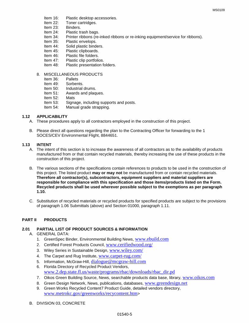
Item 16: Plastic desktop accessories. Item 22: Toner cartridges. Item 23: Binders. Item 24: Plastic trash bags. Item 34: Printer ribbons (re-inked ribbons or re-inking equipment/service for ribbons). Item 35: Plastic envelops. Item 44: Solid plastic binders. Item 45: Plastic clipboards. Item 46: Plastic file folders. Item 47: Plastic clip portfolios. Item 48: Plastic presentation folders. 8. MISCELLANEOUS PRODUCTS Item 36: Pallets Item 49: Sorbents. Item 50: Industrial drums. Item 51: Awards and plaques. Item 52: Mats Item 53: Signage, including supports and posts. Item 54: Manual grade strapping.
1.12 APPLICABILITY A. These procedures apply to all contractors employed in the construction of this project. B. Please direct all questions regarding the plan to the Contracting Officer for forwarding to the 1
SOCES/CEV Environmental Flight, 8844651. 1.13 INTENT
A. The intent of this section is to increase the awareness of all contractors as to the availability of products manufactured from or that contain recycled materials, thereby increasing the use of these products in the construction of this project.
B. The various sections of the specifications contain references to products to be used in the construction of
this project. The listed product may or may not be manufactured from or contain recycled materials. Therefore all contractor(s), subcontractors, equipment suppliers and material suppliers are responsible for compliance with this specification and those items/products listed on the Form. Recycled products shall be used wherever possible subject to the exemptions as per paragraph 1.10.
C. Substitution of recycled materials or recycled products for specified products are subject to the provisions
of paragraph 1.06 Submittals (above) and Section 01000, paragraph 1.11.
PART II PRODUCTS 2.01 PARTIAL LIST OF PRODUCT SOURCES & INFORMATION A. GENERAL DATA: 1. GreenSpec Binder, Environmental Building News, www.ebuild.com 2. Certified Forest Products Council, www.cerifiedwood.org/ 3. Wiley Series in Sustainable Design, www.wiley.com/ 4. The Carpet and Rug Institute, www.carpet-rug.com/ 5. Information, McGraw-Hill, [email protected] 6. Florida Directory of Recycled Product Vendors,
www.2.dep.state.fl.us/waste/programs/rbac/downloads/rbac_dir.pd 7. Oikos Green Building Source, News, searchable products data base, library, www.oikos.com 8. Green Design Network, News, publications, databases, www.greendesign.net 9. Green Works Recycled Content7 Product Guide, detailed vendors directory,
www.metrokc.gov/greenworks/recycontent.htm> B. DIVISION 03, CONCRETE

MS0109
01540-6
1. GranCem, granulated blast-furnace slag, www.grancem.com/ 2. Syndesis, cement-based, pre-cast product workable with wood tools, www.syndesisinc.com/ C. DIVISION 04, MASONRY 1. Heble Building Systems, autoclaved aerated concrete blocks, www.heble.com/ 2 Ytong Florida Ltd., autoclaved aerated concrete blocks, www.ytong-usa.com/ D. DIVISION 06, WOOD & PLASTICS 1. Avonite, solid surfacing, www.avonite.com/ 2. Chemical Specialties, wood treatment, www.treatedwood.com/ 3. Homasote Company, structural fiberboard, www.homasote.com/ 4. Isoboard, fiberboard composed of straw fibers and non-toxic resins, www.isoboard.com/ 5. TrusJoist Mac Millan, engineered wood products, www.homasote.com/ E. DIVISION 07, Thermal & Moisture Protection 1. Duro-Last Roofing, recycled PVC walkway pads, 1-800-2480280 2. Johns Manville, Insulation products, www.jm.com/ 3. Majestic Skylines, rubber-based slate-look roofing for steep roofs, www.majesticskylines.com/ 4. Owens-Corning, insulation products, www.owenscorning.com/ F. DIVISION 08, DOORS & WINDOWS 1. Marvin Window & Door, windows, some meeting “Energy Star Label”, www.marvin.com/ 2. Pella, energy efficient windows, www/pella.com/ G. DIVISION 09, FINISHES 1. Armstrong World Industries, Inc.-Flooring Systems, www.armstrong-floors.com/ 2. Armstrong World Industries, Inc.-Ceiling Systems, www.ceilings.com/ 3. Benjamin Moore & Co., VOC free acrylic interior latex paint, www.benjaminmoore.com/ 4. CanFibre Group Ltd., all-green medium-density fiberboard, www.canfibre.com 5. Chemrex Inc., low-e interior paint, www.chemrex.com/ 6. Collins & Aikman Floor coverings, carpet with 100% post-consumer backing,
www.powerbond.com/ 7. DesignTex, Inc., polyester panel fabric made from 100% PET fiber, www.dtex.com/ 8. Dodge-Regupol, Inc., 100% recycled rubber-flooring, www.regupol.com/ 9. Eco-sensitive modular tile, vinyl tile with 100% recycled carpet-backing, www.powerbond.com/ 10. Environmental Stone Products, stone manufactured from 100% recycled glass,
www.environmentalstone.com/ 11. Glidden: residential interior latex paints 100% free of VOC, www.icipaintstores.com/ 12 Homasote Inc., sound barrier, www.homasote.com/ 13. Isoboard Enterprises, Inc. panel made from wheat straw and non-toxic resins, 1-503-2427345 14. Marley-Flexco Co., flooring made form 95% recycled truck and bus tires, www.marleyflexco.com/ 15. The Mat Factory, Inc., interlocking roll-up tiles made from 100% postconsumer tire rubber and PVC
plastic from electric cable covers, 1-949-6453122 16. Permafirm Pad Co., carpet pads made from almost 100% recycled content, 1-800-3446977 17. Sherwin Williams, VOC compliant paints and enamels, www.sherwin.com/ 18. SierraPine Limited, formaldehyde-free particleboard and medium density fiberboard containing
recycled/recovered wood fiber, www.sierrapine.com/ 19. Summittville Tiles, impervious porcelain tiles using feldspar tailings, www.summitville.com/ 20 Tectum, natural-fiber acoustical ceiling and wall panels, www.tectum.com/ 21. Tiles with natural fibers, tiles made of a bio-alloy material and natural fibers, www.maderatile.com 22. USG Interiors, Inc., synthetic gypsum board, www.usg.com/ 23. Decorative Architectural Tiles, floor, counter & wall tile made from 100 % postconsumer glass, 1-808-
8857812 24. Forbo, linoleum-flooring utilizing renewable resources, www.forbo.com/

MS0109
01540-7
H. DIVISION 10, SPECIALTIES 1. The Access Store, modular ramping system made from 100% recycled rubber,
www.accessstoe.com/ 2. BP Solar, photovoltaic modules and systems, www.bp.com/bpsolar/index 3. Mecho Shade Systems, interior shadecloths, www.mechoshade.com/ 4. R Control, structural insulated panel (SIP), www.mechoshade.com/ I. DIVISION 12, FURNISHINGS 1. Guilford of Maine, fabric from 100% recycled materials, www.terratex.com/ 2. Phenix Biocomposites, tabletops made from soy based products free of petrochemicals, 1-800-
3248187 3. Safe Solutions, LLC, furniture manufactured from waste wood, 1-970-2473333 J. DIVISION 14, CONVEYING SYSTEMS 1. Montgomery KONE, AC girlies elevators, www.montgomery-kone.com/ K. DIVISION 16, ELECTRICAL 1. Advance Transformer Company, linear reactor ballast, www.advancetransformer.com/ 2. Artemide Inc., energy efficient cold-cathode lighting, www.artemide.com/ 3. Edison Price Lighting, track mounted metal-halide PAR 30 &38 lamps, 1-212-5216995 4. Leviton Manufacturing Corporation, Inc., occupancy sensors, www.leviton.com/ 5. Phillips Lighting, energy efficient compact fluorescent lamps, www.phillips.com/lighting 6 Osram Sylvania, mercury-free lamps and energy efficient fluorescent lamps,
www.osramsylvania.com/ 7. Sensor Switch, lighting control occupancy sensors, www.sensorswitch.com/ 8. Venture Lighting, pulse-start high performance lamp and ballast system,
www.venturelighting.com/ PART III EXECUTION 3.01 INSTALLATION A. Install materials and systems in accordance with manufacturer’s written instructions and approved
submittals. Install materials and systems in proper relation to adjacent construction and with uniform appearance.
B. Coordinate with work of other sections. C. Restore damaged finishes and test for proper function. D. Clean and protect work from damage.
END OF SECTION

MS0109
01540-8
GREEN PROCUREMENT REPORTING FORM (PER EXECUTIVE ORDER 13101)
PROJECT NUMBER:___________________________________ BLDG NUMBER:_______________________________________ PROJECT MANAGER___________________________________ PROJECT INSPECTOR:_________________________________ CONTRACTOR:________________________________________ This form is to be completed by the Contractor and submitted through 1 SOCONS to 1 SOCEC. It is the responsibility of the 1 Special Operations Civil Engineering Squadron construction inspector to submit this data to 1 Special Operations Civil Engineering Squadron's Environmental Flight (CEV) who in-turn reports it to AFSOC MAJCOM IAW E.O. 13101, Federal Acquisition, Recycling, and Waste Prevention.
RECYCLED OR RECOVERED PRODUCT
% REQUIRED (MINIMUM)
% AVAIL (ACTUAL)
QUANTITY USED/UI
EXEMPTED 1,2,3,4
-ROCK WOOL INSUL 75% -FIBERGLASS INSUL 20-25% -LOOSE FILL/SPRAY ON INSUL 75% -PERLITE COMP BOARD INSUL 23% -PLASTIC RIGID FOAM INSUL 9% -GLASS FIBER REINF FOAM INSUL 6% -PHENOLIC RIGID FOAM INSUL 5% -STRUCTURAL FIBER BD 80-100% -LAMINATED PAPER BD 100% -CEMENT/CONCRETE (FLYASH) SEE SPEC -CARPET (PET) 25-100% -PATIO BLOCKS/RUBBER 90-100% -PATIO BLOCKS/PLASTIC 90-100% -FLOOR TILES/RUBBER 90-100% -FLOOR TILES/PLASTIC 90-100% -TRAFFIC CONES 50-100% -TRAFFIC BARRICADES 80-100% -PLAYGROUND SURFACES 90-100% -RUNNING TRACKS 90-100% -COMPOST 100% -WOOD-BASED HYDRAULIC MULCH
100%
-PAPER-BASED HYDRAULIC MULCH
100%
REPROCESSED LATEX PAINT WHITE, OFF-WHITE & PASTEL COLORS
20%
REPROCESSED LATEX PAINT GREY, BROWN, EARTHTONES & OTHER DARK COLORS
50-99%
CONSOLIDATED LATEX PAINT 100%
PLASTIC/RUBBER PARKING STOPS
100%
CONCRETE CONTAINING COAL FLY ASH PARKING STOPS
20-40%
CONCRETE CONTAINING GGBF PARKING STOPS
25-70%
PLASTIC SHOWER & RESTROOM DIVIDERS/PARTITIONS
20-100%

MS0109
01540-9
CERTIFICATION
I hereby certify the Statement of Work/Specifications for the requisition/procurement of all materials listed on this form comply with EPA standards for recycled/recovered materials content. _______________ _______________ _______________ Contractor Inspector Environmental Flight The following exemptions may apply to the non-procurement of recycled/recovered content materials: 1) The product does not meet appropriate performance standards 2) The product is not available within a reasonable time frame 3) The product is not available competitively (from two or more sources)
4) The product is only available at an unreasonable price (compared with a comparable non-recycled content product.)

MS0810
01560-1
SECTION 01560 ENVIRONMENTAL PROTECTION Part 1 GENERAL 1.01 RELATED SPECIFICATION SECTIONS: A. Section 01000 – GENERAL REQUIREMENTS 1.02. SECTION INCLUDES A. The environmental protection required for this contract. 1.03. REFERENCES A. The publications listed below form a part of this specification to the extent referenced. The publications are referred to in the text by the basic designation only. 1. CODE OF FEDERAL REGULATIONS (CFR)
29 CFR 1910.1200, Hazard Communication Standard 40 CFR 110, Discharge of Oil 40 CFR 112, Oil Pollution Prevention and Response 40 CFR 122, Municipal Separate Storm Sewer Systems, Phase I & II 40 CFR 125, Criteria and Standards for the National Discharge Elimination System (NPDES) 40 CFR 260-271, Resource Conservation and Recovery Act (RCRA) 40 CFR 260-279, Hazardous Waste and Used Oil Management 40 CFR 300, National Contingency Plan 40 CFR 355, Extremely Hazardous Substances 40 CFR 403, General Pretreatment Regulations for Existing and New Sources of Pollution 49 CFR 171-172, General Information, Regulations and Definitions, and Hazardous Waste Materials Tables
2. ENVIRONMENTAL PROTECTION AGENCY (EPA)
EPA PL 96-510, Comprehensive Environmental Response Compensation and Liability Act of 1980
3. FLORIDA ADMINISTRATION CODE (FAC)
FAC 62-25, Regulation of Stormwater Discharge FAC 62-150, Hazardous Substance Release Notification FAC 62-210, Stationary Sources – General Requirements FAC 62-212, Stationary Sources – Preconstruction Review FAC 62-346, Environmental Resource Permitting in Northwest Florida FAC 62-555, Permitting and Construction of Public Water Systems FAC 62-604, Collection System and Transmission Facilities FAC 62-730, Hazardous and Solid Waste Amendments (HSWA) to RCRA FAC 62-762, Aboveground Storage Tank Systems FAC 62-770, Petroleum Contamination Site Cleanup Criteria
4. HURLBURT FIELD INSTRUCTIONS AND DIRECTIVES
Hurlburt Field Instruction 32-700, Hazardous Material Management Hurlburt Field Directive for Mercury and Fluorescent Lamps Hurlburt Field Ozone Depleting Management Plan Hurlburt Field Spill Prevention Control and Countermeasure (SPCC) Plan Hurlburt Field Installation Restoration Program (IRP) Management Action Plan Hurlburt Field Hazardous Waste Management Plan Hurlburt Field Landscape Development Plan
5. HURLBURT FIELD INSTRUCTIONS AND DIRECTIVES AFI 23-204 Organizational Fuel Tanks
AFI 32-7044, Storage Tank Compliance 1.01. QUALITY ASSURANCE A. Contractor shall establish and maintain quality control for environmental protection of all items set forth herein. The Contractor shall record on daily reports any problems in complying with laws,
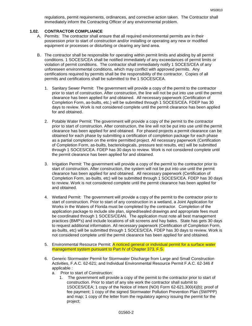
MS0810
01560-2
regulations, permit requirements, ordinances, and corrective action taken. The Contractor shall immediately inform the Contracting Officer of any environmental problem. 1.02. CONTRACTOR COMPLIANCE A. Permits: The contractor shall ensure that all required environmental permits are in their possession prior to start of construction and/or installing or operating any new or modified equipment or processes or disturbing or clearing any land area.
B. The contractor shall be responsible for operating within permit limits and abiding by all permit conditions. 1 SOCES/CEA shall be notified immediately of any exceedances of permit limits or violation of permit conditions. The contractor shall immediately notify 1 SOCES/CEA of any unforeseen environmental conditions, which may conflict with approved permits. Any certifications required by permits shall be the responsibility of the contractor. Copies of all permits and certifications shall be submitted to the 1 SOCES/CEA.
1. Sanitary Sewer Permit: The government will provide a copy of the permit to the contractor prior to start of construction. After construction, the line will not be put into use until the permit clearance has been applied for and obtained. All necessary paperwork (Certification of Completion Form, as-builts, etc.) will be submitted through 1 SOCES/CEA. FDEP has 30 days to review. Work is not considered complete until the permit clearance has been applied for and obtained.
2. Potable Water Permit: The government will provide a copy of the permit to the contractor prior to start of construction. After construction, the line will not be put into use until the permit clearance has been applied for and obtained. For phased projects a permit clearance can be obtained for each phase by submitting a certification of completion package for each phase as a partial completion on the entire permitted project. All necessary paperwork (Certification of Completion Form, as-builts, bacteriologicals, pressure test results, etc) will be submitted through 1 SOCES/CEA. FDEP has 30 days to review. Work is not considered complete until the permit clearance has been applied for and obtained.
3. Irrigation Permit: The government will provide a copy of the permit to the contractor prior to start of construction. After construction, the system will not be put into use until the permit clearance has been applied for and obtained. All necessary paperwork (Certification of Completion Form, as-builts, etc) will be submitted through 1 SOCES/CEA. FDEP has 30 days to review. Work is not considered complete until the permit clearance has been applied for and obtained.
4. Wetland Permit: The government will provide a copy of the permit to the contractor prior to start of construction. Prior to start of any construction in a wetland, a Joint Application for Works in the Waters of Florida must be completed by the contractor. Completion of the application package to include site plan, signed/sealed drawings and appropriate fees must be coordinated through 1 SOCES/CEAN. The application must note all best management practices (BMP's) and include locations of silt screens and hay bales. State has gets 30 days to request additional information. All necessary paperwork (Certification of Completion Form, as-builts, etc) will be submitted through 1 SOCES/CEA. FDEP has 30 days to review. Work is not considered complete until the permit clearance has been applied for and obtained.
5. Environmental Resource Permit: A noticed general or individual permit for a surface water
management system pursuant to Part IV of Chapter 373, F.S.
6. Generic Stormwater Permit for Stormwater Discharge from Large and Small Construction Activities, F.A.C. 62-621; and Individual Environmental Resource Permit F.A.C. 62-346 if applicable : a. Prior to start of Construction:
1. The government will provide a copy of the permit to the contractor prior to start of construction. Prior to start of any site work the contractor shall submit to 1SOCES/CEA; 1 copy of the Notice of Intent (NOI) Form 62-621.300(4)(b); proof of fee payment; 1 copy of the signed Stormwater Pollution Prevention Plan (SWPPP) and map; 1 copy of the letter from the regulatory agency issuing the permit for the project;

MS0810
01560-3
2. If F.A.C. 62-346 is applicable: 2 copies of application package signed and sealed with Form 62-346.900(1); proof of fee payment; 1 copy regulatory agency letter issuing permit number; 1 copy of the proof of submittal to regulatory agency Form 62-346.900(3) of the Construction Commencement Notice at least 48 hours prior to start of construction.
b. During Construction::
1. The contractor shall provide to 1SOCES/CEA at the end of each month, signed weekly and storm event inspection reports; and the Notice of Termination (NOT) Form 62-621.300(6) within 14 days of final stabilization of the site. Copies of the reports must be kept on-site.
2. If F.A.C. 62-346 is applicable: 1 copy of Form 62-346.900(4) As-Built Certification by the Engineer of record within 30 days after completion of construction; 1 copy Form 62-346.900(6) request for conversion of Stormwater Management Permit Construction Phase to Operation and maintenance Phase within 30 days after completion of construction.
c. Upon completion of the storm water system the contractor shall notify 1SOCES/CEA to inform the engineer of record that the system is complete. The engineer of record will prepare the all necessary paperwork, (Certification of Completion Form, as-builts, etc) to be submitted to the regulatory agency through 1 SOCES/CEA. FDEP has 30 days to review. Work is not considered complete until the permit clearance has been applied for and obtained.
7. Copies of all required forms and guidance can be found at http://www.dep.state.fl.us/ and
http://www.nwfwmd.state.fl.us/.
Part 2 PRODUCTS (NOT USED) Part 3 EXECUTION 3.01. SUBMITTALS
A. The Contractor shall submit an Environmental Protection Plan within 15 days after receipt of the notice to proceed. Approval of the Contractor's plan will not relieve the Contractor of responsibility for adequate and continuing control of pollutants and other environmental protection measures. The contractor shall obtain approval by the Contracting Officer prior to the start of construction, modification, or demolition for all project facilities and/or equipment. The plan shall include, but shall not be limited to, the following: 1. Legal Requirements: A list of Federal, State, and local laws, regulations, and permits
concerning environmental protection, pollution control and abatement that are applicable to the Contractor's proposed operations and the requirements imposed by those laws, regulations, and permits. Whenever there is a conflict between Federal, State, or local laws, regulations, and permit requirements, the more restrictive provisions shall apply.
2. Environmental Protection Procedures: Procedures to be implemented to provide the required environmental protection, to comply with the applicable laws and regulations, and to correct pollution due to accident, natural causes, or failure to follow the procedures of the environmental protection plan.
3. Drawings: Drawings showing locations of any proposed temporary excavations or embankments for haul roads, stream crossings, material storage areas, structures, sanitary facilities, and stockpiles of excess or spoil materials shall be included.
4. Solid Waste Management Plan: See paragraph titled Solid Waste.
5. Emergency Response and Spill Prevention Plan: See paragraph titled Emergency Response and Spill Prevention.
6. Hazard Material List: See paragraph titled Hazardous Materials.

MS0810
01560-4
7. Storm Water Pollution Prevention Plan: See paragraph titled Water Resources.
8. Hazard Waste Management and Disposal Plan: See paragraph titled Hazardous Waste.
9. Summary of Solid Waste Generated: See paragraph titled Solid Waste Implementation.
3.02. NATURAL RESOURCES
A. ENVIRONMENTAL RESOURCES: The environmental resources within the project boundaries and those affected outside the limits of permanent work under this contract shall be protected during the entire period of this contract. The Contractor shall confine activities to areas defined by the drawings and specifications except where tree replacement is required. Environmental protections shall be as stated in the following subparagraphs:
1. The contractor shall confine all activities to areas defined by the drawings and specifications. In areas indicated on the drawing or specified to be cleared, the Contractor shall not remove, cut, deface, injure, or destroy land resources including trees, shrubs, vines, grasses, topsoil, and land forms without permission. Trees, shrubs and other vegetation not identified for removal shall be protected against removal, injury, defacing and scarring-no ropes, cables, or guys shall be fastened to or attached to any trees for anchorage unless specifically authorized. Where such emergency use is permitted, the Contractor shall provide effective protection for land and vegetation resources at all times.
2. The Contractor shall not park vehicles or equipment within the drip line of trees. Prior to trimming or removal of trees, contractor shall coordinate with 1 SOCES/CEAN. All merchantable timber that is removed shall be limbed and stacked butt to butt in an out of the way location. Trees that are damaged or removed shall be replaced according to guidance found in the Hurlburt Field 2009 Landscape Development Plan.
3. Prior to any construction, the Contractor shall mark the areas not to be disturbed under this contract. Isolated areas within the general work area, which are to be saved and protected, shall also be marked or fenced. The Contractor's personnel shall be knowledgeable of the purpose for marking and/or protecting particular objects.
4. All earthwork shall be planned and conducted to minimize the duration of exposure of unprotected soils. Side and back slopes shall be protected as soon as practicable upon completion of rough grading. Earthwork brought to final grade shall be finished as indicated.
5. The Contractor shall construct or install temporary and permanent erosion and sedimentation control features as indicated on the drawings. Berms, dikes, drains, sedimentation basins, grassing, and mulching shall be maintained until permanent drainage and erosion control facilities are completed and operative.
6. The Contractor's field offices, staging areas, stockpile storage, and temporary buildings shall be placed in areas designated on the drawings or as directed by the Contracting Officer. Temporary movement or relocation of Contractor facilities shall be made only when approved. Borrow areas shall be managed to minimize erosion and to prevent sediment from entering nearby waters. Spoil areas shall be managed and controlled to limit spoil intrusion into areas designated on the drawings and to prevent erosion of soil or sediment from entering nearby waters. Spoil areas shall be developed in accordance with the grading plan indicated on the drawings. Temporary excavation and embankments for plant and/or work areas shall be controlled to protect adjacent areas from despoilment.
7. The Contractor shall thoroughly clean all construction equipment previously used at other sites before it is brought into the work areas, ensuring that soil residuals are removed and that egg deposits from plant pests are not present; the Contractor shall consult with the USDA jurisdictional office for additional cleaning requirements.
B. Protection of Fish and Wildlife Resources: All species of wildlife are protected on Hurlburt Field, Florida. Feeding, possessing, capturing, and attempting to capture, kill or otherwise harass wildlife is prohibited.
MS0810
01560-5
C. Black Bear and American Alligator: Black bear and American alligator sightings are common on Hurlburt Field. Law protects both animals. Feeding, possession, or harassment of an alligator is a second-degree misdemeanor. The Florida black bear is a state listed threatened species. If a bear is sighted, contact the 1 SOCES/CEA (884-4651) as soon as possible. Construction sites must be cleared of any food or drink items at the end of each workday. Any items that could attract bears must be carried off the base or placed in a dumpster. Ensure all dumpster doors and lids are securely closed at the end of the day to deter bears from entering and feeding. 3.03. CULTURAL RESOURCES
A. Historical, Archaeological, and Cultural Resources: Existing historical, archaeological, and cultural resources within the Contractor's work area will be so designated by the Contracting Officer if any has been identified. The Contractor shall take precautions to preserve all such resources as they existed at the time they were first pointed out. The Contractor shall provide and install protection measures for these resources and be responsible for their preservation during the life of the contract. Protection measures will be provided by 1 SOCES/CEA after consultation with the State Historic Preservation Officer on a case-by-case basis.
B. Artifacts Discovered During Construction: If during excavation or other construction activities any
previously unidentified or unanticipated resources are discovered or found, all activities that may damage or alter such resources shall be temporarily suspended. Resources covered by this paragraph include but are not limited to: any human skeletal remains or burials; artifacts; shell, bone, charcoal, or other deposits; rocks or coral alignments, pavings, wall, or other constructed features; and any indication of agricultural or other human activities. Upon such discovery or find, the Contractor shall immediately stop work and notify the Contracting Officer and 1 SOCES/CEA.
3.04. WATER RESOURCES A. The Contractor shall keep construction activities under surveillance, management, and control to avoid pollution of surface and ground waters. Toxic or hazardous chemicals shall not be applied to soil or vegetation when such application may cause contamination. Monitoring of water areas affected by construction shall be the Contractor's responsibility.
B. Wetlands: Monitoring of wetland and water resources affected by construction activities shall be the responsibility of the Contractor. During construction, best management practices (BMP’s) will be required to maintain buffer areas and soil erosion measures near water areas that could be adversely affected by construction activities. Contractor should plan for all events which will cause extreme conditions that may result in failure of BMP’s. All fines and penalties assessed for wetlands violations affected by construction activities shall be the responsibility of the contractor.
C. Stormwater: The contractor shall use proper control and management techniques to ensure stormwater criteria are met in accordance with Federal, State, and local stormwater regulations. Runoff from the construction site or from storms shall be controlled, retarded, and diverted as indicated on the drawings to protected drainage courses by means of diversion ditches, benches, berms, and by any measures required by area wide plans under the Clean Water Act. Prior to any project that disturbs greater than one acre, the contractor must complete a Notice of Intent with FDEP and have a Stormwater Pollution Prevention Plan approved by 1 SOCES/CEA. A notice of termination must also be filed at the conclusion of the project.
D. Silt screens must be installed prior to start of construction. Silt screens and/or other erosion control devices shall be installed on construction sites that are in or near wetland areas. Silt screens shall consist of trenched and staked filter fabric and trenched and staked hay bales. Filter fabric must be toed 8 inches into the soil to avoid sediments that would be transported via water under the screen. Hay bales must be placed end to end on the down stream side of the screen and be trenched and staked firmly into the ground. Chinking is usually required to fill gaps between the bales. Silt screens must be maintained properly. Screens and other control devices must be inspected once a week and after any rainfall event totaling 1/2 inch or more to ensure they are in good repair and functioning properly. In areas that experience high flow rates, extra precautions will be necessary to stabilize screens. Trenching of hay bale barriers is required to adequately control runoff. A series of screens may have to be installed in waters that are especially turbid to properly filter out sediments. Silt screens will remain in place and properly maintained until the site is properly stabilized with sod or seeding.
MS0810
01560-6
E. In some cases where severe erosion results in waters becoming turbid despite control measures, regular turbidity monitoring and documentation shall be necessary. Any such documentation shall be forwarded to 1 SOCES/CEA for review.
F. Stream Crossings shall allow movement of materials or equipment without violating water pollution control standards of the Federal, State or local government.
G. Landscaping: All new landscaping will be watered in accordance with the current stage of the Hurlburt Field Water Conservation Policy. All irrigation work will need to be coordinated with 1 SOCES/CEA & 1SOCES/CEC. The use of potable water for irrigation systems is prohibited.
H. Contractor is not authorized sewage holding tanks on base and must procure a portable toilet service contract. The contract must include the correct removal of sewage and maintenance of the portable toilet.
3.05. AFFIRMATIVE PROCUREMENT A. Per Executive Order 13101, the Environmental Protection Agency (EPA) requires that all government purchases of designated items shall contain at least the minimal amount of post- consumer and/or total recovered materials. EPA-designated items fall into the following categories:
• Bio-based Products • Miscellaneous Products • Park and Recreation Products
• Construction Products • Non-Paper Office Products • Transportation Products • Landscape Products • Paper and Paper Products • Vehicular Products Specific requirements can be found at the EPA’s website: http://www.epa.gov/cpg/products.htm. Also, see section 01540: Affirmative Procurement.
3.06. AIR RESOURCES A. Equipment operation and activities or processes performed by the Contractor in accomplishing the specified construction shall be in accordance with the State rules and all Federal emission and performance laws and standards. Ambient Air Quality Standards set by the Environmental Protection Agency shall be maintained. The Contractor shall monitor all air areas affected by the construction activities. Monitoring results will be periodically reviewed by 1 SOCES/CEA to ensure compliance.
B. Ozone Depleting Substances: The contractor shall adhere to Air Force and HFLD policies regarding halons and chlorofluorocarbons (CFCs). The contractor shall not introduce any Class I Ozone Depleting Substances (ODS) to Hurlburt Field during the course of this contract. The contractor shall be responsible for the recovery and recycling of all Class II ODS, including any necessary sampling marking, labeling, and disposal. The contractor may access the Hurlburt Field ODS Management Plan for guidance. However, the contractor shall remain ultimately responsible for any ODS work related to these tasks. Any work performed on equipment containing ODS used as refrigerants shall only be done by EPA certified technicians. Certification cards shall be on their person at all times. Intentional venting of ODS is strictly prohibited. Any work performed on equipment containing ODS used as refrigerants should only be done by EPA- certified technicians. Certification cards should be on their person at all times.
C. Particulates: Dust particles; aerosols and gaseous by-products from construction activities; and processing and preparation of materials, shall be controlled at all times, including weekends, holidays and hours when work is not in progress. The Contractor shall maintain excavations, stockpiles, haul roads, permanent and temporary access roads, plant sites, spoil areas, borrow areas, and other work areas within or outside the project boundaries free from particulates which would cause the air pollution standards to be exceeded or which would cause a hazard or a nuisance. The Contractor must have sufficient, competent equipment available to accomplish these tasks. Particulate control shall be performed as the work proceeds and whenever a particulate nuisance or hazard occurs by employing BMP’s.
D. Employ the following BMP’s to minimize air pollutants:

MS0810
01560-7
1. Limit the entry/exit of vehicles to the site to minimize track-in and track-out of aggregate and construction materials. 2. Apply water or other dust suppressants to unpaved roads.. 3. Keep stock piles and open containers covered when not in use. 4. Landscape or vegetate as soon as practical. 5. Use water-based paints and low VOC surface coatings as per section 09000..
3.07. SOLID WASTE A. The contractor shall make every attempt to reduce the generation of solid and hazardous waste to the maximum extent possible. The contractor shall utilize the Base Recycling Center (884- 7577) for any office paper, cardboard, plastic, or metal wastes related to a project whenever possible. All wastes, whether recycled or landfilled, shall be weighed prior to disposal. Detailed disposition information shall be reported by the fifth day of each quarter to 1 SOCES/CEA. Solid wastes (excluding clearing debris) shall be placed in containers and emptied, recycled or land-filled, on a regular schedule. Segregation measures shall be employed so that no hazardous or toxic waste is co-mingled with solid waste. The Contractor shall transport solid waste (items not utilized by Base Recycling Center) off Government property and dispose of it in compliance with Federal, State, and local requirements for solid waste disposal. Vehicles used in transporting refuse shall be covered and enclosed to prevent spillage. Expense and cleanup of any spills on or off base are always the responsibility of the contractor.
B. Solid Waste Management Plan: The Solid Waste Management Plan, refer to paragraph titled Submittals, shall include, but not limited to, the following:
1. Description and estimated quantities of the proposed job-site waste to be generated.
2. Landfill Options: The name of the landfill(s) where trash will be disposed of, applicable landfill tipping fee(s), and the projected cost of disposing of all project waste in the landfill(s).
3. Waste Diversion: A list of the waste materials from the project that will be separated for reuse, salvage, or recycling, associated weights and estimated cost savings shall be reported to 1 SOCES/CEA by the 5th day of each quarter.
4. Handling Procedures: A description of the means by which any waste materials identified in item 3 above will be stored and a description of the means to be employed in recycling the above materials consistent with requirements for acceptance by designated facilities.
5. Transportation: A description of the means of transportation of the waste and recycled materials (whether materials will be site-separated and self-hauled to designated center, or whether mixed materials will be collected by a waste hauler and removed from the site). Request manufacturers to use the minimum packaging required for protection and identification of project products, and to use packaging materials with recycled content where economically feasible in accordance with FAR, Executive Order 13101, and the Hurlburt Field Affirmative Procurement Plan.
6. Submit cost information on the Solid Waste Management Plan for Solid Waste Disposal, Recycling, Cost savings for wastes diverted from the landfill to the Contracting Officer by 5th day of each quarter.
C. Solid Waste Management Plan Implementation
1. The Contractor shall designate an on-site party (or parties) responsible for instructing workers and overseeing and documenting results of the Solid Management Plan for the project.
2. The Contractor shall distribute copies of the Solid Management Plan to key personnel and submit the plan to the Contracting Officer as part of the Environmental Protection Plan (see Submittals section).
3. The Contractor shall provide on-site instruction of appropriate separation, handling, and recycling, salvage, reuse, and return methods to be used by all parties.

MS0810
01560-8
4. The Contractor shall lay out and label a specific area to facilitate separation of materials for
potential recycling, salvage, reuse, and return. Recycling and waste bin areas are to be kept neat and clean and clearly marked in order to avoid contamination of materials.
5. The Contractor shall submit with each Application for Progress Payment, a Summary of Solid Waste Generated by the project to 1 SOCES/CEA. Failure to submit this information shall render the Application for Payment incomplete and shall delay Progress Payment. The Summary shall be submitted on a form acceptable to the Owner and shall contain the following information: a. The amount (in tons) of material land-filled from the project, the identity of the landfill, the
total amount of tipping fees paid at the landfill, and the total disposal cost. Include manifests, weight tickets, receipt, and invoices.
b. For each material recycled, reused or salvaged from the project, the amount (in tons), the date removed from the job-site, the receiving party, the transportation cost, the amount of any money paid or received for the recycled or salvaged material, and the net total cost or savings of salvage or recycling each material. Attach manifests, weight tickets, receipts, and invoices.
c. Any serviceable or salvageable items not accepted by DRMO or Base Supply will become the property of the Contractor and will be properly handled, transported, and disposed of off-base by the Contractor in conformance with the Solid Management Plan and with all applicable federal, state, and local regulations.
3.08. HAZARDOUS WASTE (Includes Special and Universal Waste)
A. The contractor shall be considered the primary co-generator for all hazardous wastes generated throughout the duration of the contract. All hazardous waste management activities shall be coordinated and approved by 1 SOCES/CEAN.
B. The contractor’s key personnel must attend the Hurlburt Field Hazardous Waste Awareness briefing prior to starting work on base. For reservations, contact Randy Trent at (850) 884-7923 or email [email protected].
C. The contractor is responsible for the management and disposal of all hazardous wastes he/she generates on base. All cost for labor, equipment, materials, transportation, and other services required to comply with federal, state and local laws governing hazardous/special waste management and disposal are the responsibility of the contractor.
D. The contractor shall characterize their waste streams using specific and technical knowledge, MSDS,s and/or sampling and analysis. This responsibility also includes preparation of waste profile sheets, manifests (regulated and non regulated) packaging, marking and labeling of wastes containers.
E. The contractor shall manage all hazardous waste, special waste, and universal waste IAW the HFLD Hazardous Waste Management Plan. The contractor shall ensure that all employees, including their subs, comply with the rules and procedures outlined in the Hurlburt Field Hazardous Waste Management Plan.
F. The contractor shall be familiar with and have immediate access to the following publications and regulations: 1. Environmental Protection Agency (EPA): Title 40 Code of Federal Regulations, Parts 260-
279 2. Department of Transportation (DOT): Title 49 Code of Federal Regulations, Parts 171-177 3. Hurlburt Field Hazardous Waste Management Plan
G. If transportation of Hazardous Wastes is required, the contractor shall possess or ensure the
transportation company used for transportation of hazardous waste has a valid state and federal EPA identification number and all DOT requirements are met.

MS0810
01560-9
H. The contractor shall prepare profiles and manifests for all waste transported off base for disposal.
A designated representative from 1 SOCES/CEAN, Environmental Element, must approve and sign the hazardous waste/non-hazardous waste manifest. Contractor shall ensure the signed manifest is returned to 1 SOCES/CEAN within 45 days from the time it’s received at the disposal facility.
I. The Hurlburt Field Hazardous Waste Storage Facility may accept contractor’s hazardous, special and universal waste (that was generated on base) depending on type of waste, quantities generated and provisions of the contract. 1 SOCES/CEAN must approve acceptance of the waste before it’s generated.
3.09. HAZARDOUS MATERIALS A. For the purposes of the document, Hazardous Materials (HM) are defined as any product, material, chemical or substance listed in 49 CFR 172.101 (revised) and 40 CFR 302-304 (revised). Specifically, a HM is any substance or material, in any quantity or form that has the potential to harm human health or the environment or displays specific characteristics (reactive, corrosive, ignitable, and toxic).
B. Absolutely no HM shall be brought onto Hurlburt Field until that material is registered with the Hazardous Materials Pharmacy (HAZMART) per Hurlburt Field Instruction 32-7001 and AFI 32-7086, Hazardous Material Management. This requirement shall apply for all HM that the contractor intends to bring onto government property for any/all processes or applications. The contractor shall submit a complete hazardous material inventory list including Material Safety Data Sheets and any other supporting documentation for each HM used prior to contract start or introduction of that material to Hurlburt Field. The HM inventory shall include the contract number, performance period, and a contractor point of contact for HM matters. All excess material and empty containers are the responsibility of the contractor and shall be removed accordingly at the end of the contract. Should contractor HM requirements change during the performance period, the Contractor shall immediately notify the HAZMART and Base HM Program Manager of such changes in writing.
C. Storage of Hazardous Materials: All HM shall be stored at Hurlburt Field with approval and coordination from 1 SOCES/CEAN, the base Fire Department (1 SOCES/CEF), and Wing Safety. The contractor shall observe HM storage practices in accordance with regulations, policies, plans and procedures employed by the base.
D. All contractor personnel shall immediately report to the Contracting Officer and 1 SOCES/CEAN any hazardous materials, substances (including suspect asbestos containing materials), chemicals, or contaminated areas encountered. Further, the contractor personnel shall immediately cease work in the area unless the work is of an emergency nature and the risk of exposure can be mitigated by the use of personal protective equipment (PPE) or clothing. The government will determine the best means of sampling and corrective action and will notify the contractor accordingly.
E. The contractor shall not use, store, or handle any Class I ODS during the course of this contract.
F. All hazardous materials and waste resulting from construction projects (including renovation/repair and demolition) shall be managed in accordance with local, state, federal and Hurlburt Field rules and regulations.
3.10. TOXIC WASTE A. Asbestos: All asbestos work must be accomplished in accordance with federal, state, and local laws and the Hurlburt Field Asbestos Management Plan. See Section 02075.
1. Notice of Asbestos Renovation or Demolition, DEP Form 62-257.900(1) must be submitted to Florida Department of Environmental Protection at least 10 working days prior to any demolition and/or renovation regardless of whether asbestos is present or not. A copy of this notification and all asbestos surveys conducted must be provided to 1 SOCES/CEAN prior to performing any work. Upon completion of any asbestos abatement, the contractor will provide copies of all disposal waste manifests to 1 SOCES/CEAN, Toxic Substance Program Manager.

MS0810
01560-10
2. A copy of all submittals must be provided to 1 SOCES/CEAN with adequate time built in for review.
3. The use of materials, products or equipment containing asbestos will not be allowed in the construction of this project. See sample list below.
4. Prior to the commencement of construction, the prime contractor, each subcontractor and material/equipment supplier shall provide the Contracting Officer and 1 SOCES/CEAN with a Notarized statement that to the best of their knowledge, no asbestos will be used in the construction of this project. Additionally, the contractor must have available the most current Material Data Safety Sheet proving the materials contain no asbestos.
5. Sample list of Asbestos Containing Materials (ACM): Note: The following list does not include every product/material that may contain asbestos. It is intended as a general guide to show which types of material may contain asbestos.
• Cement pipes • Cement wallboard • Cement siding • Asphalt floor tile • Vinyl floor tile • Vinyl sheet flooring • Flooring backing • Construction mastics • Acoustical plaster • Decorative plaster • Textured paints/coatings • Ceiling tiles & lay-in-panels • Spray-applied
insulation • Blown-in insulation • Fireproofing materials
• • Taping compounds (thermal)
• Packing materials (for wall/floor penetrations)
• High temperature gaskets
• Laboratory hoods • Laboratory gloves • Fire blankets & table tops • Fire curtains • Elevator equipment
panels • Elevator brake shoes
• HVAC duct insulation • Boiler insulation • Breeching insulation • Ductwork flexible fabric • Cooling towers • Pipe insulation (corrugated
connections air cell, block, etc.) • Heating and electrical • Electrical panel partitions • Electrical cloth ducts • Spackling compounds • Chalkboards • Roofing shingles • Roofing felt • Base flashing • Thermal paper products • Fire doors • Caulking/putties • Adhesives • Wallboard • Joint compounds • Vinyl wall coverings • Electrical wiring insulation
Caution needs to be taken to ensure materials purchased do not contain one or more % asbestos by volume.
B. Lighting Ballast: When fluorescent and mercury vapor fixtures are removed, the ballast must be examined for PCB labeling. Ballast is presumed to contain PCBs unless they are clearly labeled “ NO PCBs”. Suspected ballast must be removed and disposed IAW Hurlburt Field directives. C. Lead Based Paint: No paint containing lead shall be used during the course of this contract. The Occupational Health and Safety Act (OSHA) Lead Construction Standard, 29 CFR 1926.62 is in effect whenever materials are disturbed that contain any amount of lead. This will require contractors disturbing lead-based paint to institute medical surveillance, training, engineering controls, worker protection measures and employee monitoring until monitoring results per the lead paint standard demonstrate that employee exposure is below the action level and permissible exposure limit. The contractor on site must maintain all documentation regarding lead exposure by either historical data or project data. This data shall also be made available to 1 SOCES/CEAN upon completion of the project.
1. Prior to the commencement of construction, the prime contractor, each subcontractor and material/equipment supplier shall provide to the Contracting Officer and 1 SOCES/CEAN with a Notarized statement that to the best of their knowledge, no lead based paint will be used in the construction of this project. Additionally, the contractor must have available the most current Material Data Safety Sheet proving that the paint does not have any lead content. If lead based paint has been identified, copies of surveys must be forwarded to 1 SOCES/CEAN, Toxic Substance Program Manager.

MS0810
01560-11
2. The contractor shall be responsible for collection and disposal of all lead paint chips and lead
paint-contaminated materials, and for accumulation of these chips/materials on site. The contractor shall test the paint materials, provide containers for proper disposal, and transport any resulting hazardous waste to an appropriate hazardous waste accumulation area should it test positive as hazardous waste. All necessary accumulation, disposal activities and documentation shall be coordinated with the 1 SOCES/CEA flight.
3. A copy of contractor’s exposure assessment data shall be provided to 1 SOCES/CEAN.
4. Copies of all lead paint-related documentation generated from this project, including lead testing, air monitoring and hazardous waste manifests, shall be provided by the Contractor to the Contracting Officer. A copy shall be forwarded to 1 SOCES/CEAN within 10 working days of task completion.
5. On Military Family Housing Projects, there shall be in-depth coordination with the 1SOCES/CEAC flight to allow for resident notification and necessary arrangements.
The contractor is strongly encouraged to coordinate closely with 1SOCES/CEAN for any required guidance on this critical issue. 6. Contractors performing renovation, repair and painting projects that disturb lead-based paint
in homes, child care facilities, and schools built before 1978, must be certified and must follow specific work practices to prevent lead contamination (40 CFR Part 745). Upon completion of any lead base paint abatement, the contractor will provide copies of all disposal waste manifests to 1 SOCES/CEAN, Toxic Substance Program Manager.
3.11. SPILL PREVENTION:
A. The contractor is required to familiarize their employees with spill procedures, fire suppression systems and Material Safety Data Sheets for all materials used and/or stored at the project site. In the event of an oil, fuel or chemical spill, the contractor shall immediately notify the Hurlburt Field Fire Department by calling 911. The contractor shall also notify the Contracting Officer (CO) and provide a detailed, written spill report to 1 SOCES/CEAN within 24 hours describing the events of the release. Costs incurred from contractor related spills are the responsibility of the contractor. The contractor shall reimburse any government cost associated with spill response and clean-up.
B. The contractor shall provide and maintain spill containment equipment, sufficient in both type and
quantity, at all sites involving the storage, use or handling of hazardous waste and hazardous materials. The type of spill equipment and quantity required will be identified in the contractor’s site specific contingency plan. Equipment and materials must be adequate to contain any release and secondary containment must be in use as required.
C. If the contractor is required to stockpile contaminated soil for testing prior to disposal, the CO will inform the contractor of the stockpile location after consultation with 1 SOCES/CEAN.
D. Contractor vehicle and heavy equipment maintenance (including oil changing, lubrication, and
vehicle washing) is not authorized on base.
E. All fuel, oil, and chemical spills that occur on Hurlburt Field (regardless of amount) must be immediately reported to the base Fire Department by calling 911.
3.12. LABORATORY REQUIREMENTS A. The contractor shall as required use a laboratory capable of performing all analysis required to determine Resource Conservation and Recovery Act (RCRA) characteristics such as, but not limited to, Toxicity Characteristic Leaching Procedure (TCLP) metals, TCLP volatile and semi- volatile organic, flashpoint, reactivity, and pH. The laboratory shall also be capable of performing any analysis required to determine the applicability of the used oil criteria detailed in 40 CFR, Part 279. The contractor shall ensure that all analytical work is performed IAW the methods and

MS0810
01560-12
procedures, including QA/QC requirements, detailed in EPA SW-8467. The analytical laboratory shall be capable of providing accurate, complete data within eight (8) working days. Field analysis and portable instrumentation shall not be used to fulfill laboratory requirements. The contractor shall retain all data on file for a minimum of three years and keep it readily available for inspection by any authorized agency, including 1 SOCES/CEA Asset Management Flight. Chain- of-custody documents shall be included with these records. At the end of the contract, all of these data files may be transferred to 1 SOCES/CEA. 3.13. POST CONSTRUCTION CLEANUP A. The Contractor shall clean up all areas affected by construction and restore them back to their original condition to include landscaping, planting of trees, grass, and shrubs damaged by construction; and raking and disposal of debris such as roof shingles, paper, nails, glass, sheet metal, bricks, and waste concrete. Backfilled areas shall be compacted properly and replanted with grass.
3.14. INSTALLATION RESTORATION PROGRAM (IRP) A. Contractors and Project Managers (PM) planning projects on Hurlburt Field should be aware of the potential to encounter soil/groundwater contamination throughout many areas of the base. The following guidance has been developed to assist in the planning, designing and construction of projects in possibly contaminated areas (IRP sites). The first set of guidance is the most stringent and involves projects planned in an area that has known contamination and regulatory Land Use Controls. The second set of guidance applies to projects planned near a known IRP site with suspected contamination. The last set of guidance is general and applies to any areas of the base where contamination has not been confirmed. It is imperative that planners, designers and contractors involve 1 SOCES/CEA early and often in the planning, designing, and construction process to minimize the impact that contaminated soils/groundwater may have on their project. B. Projects located on a site with known soil and/or groundwater contamination with land use controls:
1. There are land use controls on this area imposed by an environmental regulatory agency designed to protect public health.
2. Project Manager should investigate and plan to ensure all monitor wells/cleanup systems are avoided.
3. Project Manager should submit detailed work plans to 1 SOCES/CEA early in planning stages so 1 SOCES/CEA can obtain concurrence from the regulatory agencies on project details.
4. Project Manager should educate workers on potential to encounter contamination and also should ensure workers are adequately protected with personal protective equipment.
5. If unusual soil or groundwater color/odor is encountered during subsurface work, contact 1 SOCES/CEA.
C. Projects located near a site with known or suspected soil and/or groundwater contamination without land use controls:
1. If unusual soil or groundwater color/odor is encountered during subsurface work, contact 1 SOCES/CEA.
2. Project Manager should investigate and plan to ensure all monitor wells/cleanup systems are avoided.
3. Project Manager should educate workers on potential to encounter contamination and also should ensure workers are adequately protected with personal protective equipment.
D. Sites without land use controls and not in close proximity to known contamination or IRP site:
1. If unusual soil or groundwater color/odor is encountered during subsurface work, contact 1 SOCES/CEA.

MS0810
01560-13
2. Project Manager should educate workers on potential to encounter contamination and also should ensure workers are adequately protected with personal protective equipment.
E. Be aware that the regulatory agency can halt the project for long periods of time due to the discovery of contamination. 1 SOCES/CEA is committed to expediting projects with IRP compliance related issues.
3.15 STORAGE TANKS A. 1 SOCES/CEA must approve the use of fuel storage tanks on base, and the contractor must ensure adequate spill containment (spill kits) for any tanks approved for use on Hurlburt Field. The contractor must have written spill procedures for tanks and heavy equipment that they use on base. Temporary gasoline storage is NOT permitted on base.
B. POL/Storage Tanks: Storage tanks and POL can be a source of contamination if not managed
appropriately. Contractor personnel obtaining fuels from Storage Tanks agree to follow all 62-762 FAC and the following list of Air Force Technical Order’s to ensure compliance: 37-1-1, 37A-1-101, 42B-1-1, 42B-1-1S-2, 42B-1-16, 42B-1-22, 42B-1-23, and 42C-1-12.
C. Contractor must contact 1SOCES/CEA for a copy of Hurlburt Field’s Spill Prevention Control and
Countermeasure Plan (SPCC), if storage tanks us is approved. A number of Federal and State agencies have regulations pertaining to pollution prevention and emergency response requirements of oil and hazardous storage and transfer facilities. The Hurlburt Field SPCC Plan has been developed to address the issues of spill prevention, discharge containment / cleanup, and emergency response actions.
END OF SECTION
MS0109
01580-1
SECTION 01580 PROJECT IDENTIFICATION SIGN PART 1 GENERAL 1.01 RELATED SPECIFICATION SECTIONS: A. Section 01000 – GENERAL REQUIREMENTS 1.02 SECTION INCLUDES: A. Project Identification Sign. 1.03 QUALITY ASSURANCE: A. Design sign and structure in accordance with drawing shown on page 2 of this specification. B. Use experienced professional sign painter. C. Finishes shall be adequate to withstand weathering, fading, and chipping, for duration of construction. PART 2 PRODUCTS 2.01 SIGN MATERIALS: A. Structure and Framing: New, pressure-treated 4 x 4 x 12' support posts. B. Sign Surfaces: Exterior grade plywood, A-C, 1/2" thick, 4'-0" x 8'-0". C. Paint and Primers: Exterior professional quality, high-gloss alkyd enamel. D. Lettering: Exterior quality paint as per above, or pre-cut vinyl self-adhesive products, in accordance with
attached drawing. PART 3 EXECUTION 3.01 INSTALLATION: A. Install project identification sign within 15 days after Notice to Proceed. 1. Install at a location of high public visibility adjacent to main entrance to site. 2. Erect sign surface plumb and level. Anchor securely. 3. Paint exposed surfaces of sign, supports, and framing. 3.02 MAINTENANCE: A. Maintain sign and supports clean. B. Repair deterioration and damage. 3.03 REMOVAL: A. Remove signs, framing, supports, and foundations at completion of project and restore the area.

MS0109
01580-2
1 SP
ECIA
L O
PER
ATI
ON
S C
IVIL
EN
GIN
EER
SQ
UA
DR
ON
INU
.S. A
IR F
OR
CE
PRO
JEC
T
PAR
TNER
SHIP
WIT
H 1
SPE
CIA
L O
PS C
ON
TRA
CTI
NG
SQ
UA
DR
ON
PRO
JEC
T TI
TLE
PRO
JEC
T TI
TLE
GEN
ERA
L C
ON
TRA
CTO
RN
AM
E O
F C
ON
TRA
CTO
RA
RC
HIT
ECT-
ENG
INEE
R1
SOC
ES/C
ECC
8'-0
"
4'-0"
12
3 4 5
67
A BC
D E F G H
1. U
SE 1
/2" G
RAD
E A-
C E
XTER
IOR
PLY
WO
OD
2. P
AIN
T W
ITH
EXT
ERIO
R G
LOSS
EN
AMEL
:
a. 1
CO
AT P
RIM
ER
b. 2
CO
ATS
CO
LOR
#20
122,
FED
. STA
ND
ARD
595
B
c. W
HIT
E LE
TTER
S3.
MO
UN
T SE
CU
REL
Y O
N P
RES
SUR
E TR
EATE
D 4
x4s,
W
ITH
BO
TTO
M 4
' FR
OM
GR
ADE
4. R
EMO
VE S
IGN
AFT
ER C
OM
PLET
ION
OF
C
ON
STR
UC
TIO
N
SPAC
EA B C D E F G H
1" 6" 5"1"6" 3"
HEI
GH
T5" 1"
2"3
2"6 7
2"
4 55" 5"
HEI
GH
TLI
NE
1 22" 2"
3/16
"
3/16
"3/
16"
1/2"
1/2"
STR
OKE
3/16
"3/
16"
LETT
ER
END OF SECTION
MS0109
01600-1
SECTION 01600 MATERIAL AND EQUIPMENT PART 1 GENERAL 1.01 RELATED SPECIFICATION SECTIONS: A. Section 01000 – GENERAL REQUIREMENTS 1.02 PRODUCTS A. Products means new material, machinery, components, equipment, fixtures and systems forming the
Work. Does not include machinery and equipment used for preparation, fabrication, conveying and erection of the work. Products may also include existing materials or components required for reuse.
B. Do not use materials and equipment removed from existing premises except as specifically permitted by
the Contract Documents and approved by the Contracting Officer. C. Provide interchangeable components of the same manufacturer for similar components. 1.03 TRANSPORTATION AND HANDLING: A. Transport and handle products in accordance with manufacturer's instructions. B. Promptly inspect shipments to assure that products comply with requirements, quantities are correct, and
products are undamaged. C. Provide equipment and personnel to handle products by methods to prevent soiling, disfigurement or
damage. 1.04 STORAGE AND PROTECTION: A. Store and protect products in accordance with manufacturer's instructions, with seals and labels intact and
legible. Store sensitive products in weathertight, climate controlled enclosures.
B. For exterior storage of fabricated products, place on sloped supports above ground. C. Cover products subject to deterioration with impervious sheet covering. Provide ventilation to avoid
condensation. D. Store loose granular materials on solid flat surfaces in a well-drained area. Prevent mixing with foreign
matter.
E. Provide equipment and personnel to store products by methods to prevent soiling, disfigurement or damage.
F. Arrange storage of products to permit access for inspection. Periodically inspect to assure products are
undamaged and are maintained under specified conditions. 1.05 PRODUCT OPTIONS: A. Products Specified by Reference Standards or by Description Only: Any product meeting those standards
or description. B. Products Specified by Naming One or More Manufacturers with a Provision for substitutions: Submit a
request for substitution for any manufacturer not named. 1.06 SUBSTITUTIONS: A. Substitutions will be considered under provisions of Section 01000. B. Document each request with complete data substantiating compliance of proposed substitution with
Contract Documents. C. A request constitutes a representation that the contractor:
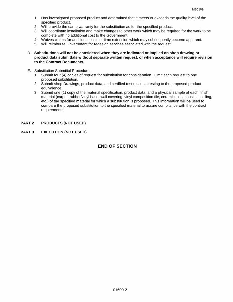
MS0109
01600-2
1. Has investigated proposed product and determined that it meets or exceeds the quality level of the specified product.
2. Will provide the same warranty for the substitution as for the specified product. 3. Will coordinate installation and make changes to other work which may be required for the work to be
complete with no additional cost to the Government. 4. Waives claims for additional costs or time extension which may subsequently become apparent.
5. Will reimburse Government for redesign services associated with the request. D. Substitutions will not be considered when they are indicated or implied on shop drawing or
product data submittals without separate written request, or when acceptance will require revision to the Contract Documents.
E. Substitution Submittal Procedure: 1. Submit four (4) copies of request for substitution for consideration. Limit each request to one
proposed substitution. 2. Submit shop Drawings, product data, and certified test results attesting to the proposed product
equivalence. 3. Submit one (1) copy of the material specification, product data, and a physical sample of each finish
material (carpet, rubber/vinyl base, wall covering, vinyl composition tile, ceramic tile, acoustical ceiling, etc.) of the specified material for which a substitution is proposed. This information will be used to compare the proposed substitution to the specified material to assure compliance with the contract requirements.
PART 2 PRODUCTS (NOT USED) PART 3 EXECUTION (NOT USED) END OF SECTION
MS0109
01650-1
SECTION 01650 STARTING OF SYSTEMS PART l GENERAL 1.01 RELATED SPECIFICATION SECTIONS: A. Section 01000 – GENERAL REQUIREMENTS 1.02 STARTING SYSTEMS A. Coordinate schedule for start-up of various equipment and systems. B. Notify project inspector 7 days prior to start-up of each item. C. Verify that each piece of equipment or system has been checked for proper lubrication, drive rotation, belt
tension, control sequence, or other conditions, which may cause damage. D. Verify that tests, meter readings and specified electrical characteristics agree with those required by the
equipment or system manufacturer. E. Verify wiring and support components for equipment are complete and tested. F. Execute start-up under supervision of responsible manufacturer's representative if required by manufacturer or contractors' personnel in accordance with manufacturers' instructions. G. When specified in individual Specification Sections, require manufacturer to provide authorized representative to be present at site to inspect, check and approve equipment or system installation prior to start-up, and to supervise placing equipment or system in operation. H. Submit a written report in accordance with applicable Section of Specifications that equipment or system has been properly installed in accordance with manufacturer's installation instructions and is functioning
correctly. 1.03 DEMONSTRATION AND INSTRUCTIONS A. Demonstrate operation and maintenance of products to Government personnel 7 days prior to date of final
inspection. B. Utilize operation and maintenance manuals as basis for demonstration. Review contents of manual with
government personnel in detail to explain all aspects of operation and maintenance. C. Demonstrate start-up, operation, control, adjustment, trouble-shooting, servicing, maintenance, and shutdown of each item of equipment at scheduled times, at equipment designated location. D. Prepare and insert additional data in operations and maintenance manuals when need for additional data
becomes apparent during instruction. 1.04 TESTING, ADJUSTING AND BALANCING A. Contractor will appoint, employ and pay for services of an independent firm to perform testing, adjusting
and balancing. B. Reports will be submitted by the independent firm to the Contracting Officer indicating observations and
results of tests and indicating compliance or non-compliance with specified requirements and with the requirements of the Contract Documents. PART 2 PRODUCTS (NOT USED); PART 3 EXECUTION (NOT USED) END OF SECTION

MS0109
01700-1
SECTION 01700 CONTRACT CLOSEOUT PART 1 GENERAL 1.01 RELATED SPECIFICATION SECTIONS: A. Section 01000 – GENERAL REQUIREMENTS 1.02 SECTION INCLUDES A. Closeout procedures. B. Final cleaning. C. Adjusting. D. Project record documents. E. Operation and maintenance data. F. Spare parts and maintenance products. G. Warranties. H. Maintenance service. 1.03 CLOSEOUT PROCEDURES A. Submit written certification that Contract Documents have been reviewed, Work has been inspected,
and that Work is complete in accordance with Contract Documents and ready for final inspection. B. Upon completion of final inspection, correct punch list items to the satisfaction of the government, and
submit all closeout documents, the Government shall take beneficial occupancy of building (BOD). All warranties will start when government takes BOD.
C. Provide closeout submittals to Government as required by contract documents. Complete and submit
attached closeout checklist. 1.04 FINAL CLEANING A. Execute final cleaning prior to final inspection. B. Clean interior and exterior glass, surfaces exposed to view; remove temporary labels, stains and
foreign substances, polish transparent and glossy surfaces, vacuum and remove any stains from carpeted and soft surfaces.
C. Clean equipment and fixtures to a sanitary condition with cleaning materials appropriate to the surface
and material being cleaned. D. Replace filters of operating equipment. E. Clean debris from roofs, gutters, downspouts, and drainage systems. F. Clean site; sweep paved areas, rake clean landscaped surfaces. G. Remove waste and surplus materials, rubbish, and construction facilities from the site. 1.05 ADJUSTING A. Adjust operating products and equipment to ensure smooth and unhindered operation. 1.06 PROJECT RECORD DOCUMENTS A. Maintain on site one set of the following record documents; record actual revisions to the Work:

MS0109
01700-2
1. Drawings. 2. Specifications. 3. Addenda. 4. Change Orders and other modifications to the Contract. 5. Reviewed Shop Drawings, Product Data, and Samples. 6. Manufacturer's instruction for assembly, installation, and adjusting. B. Ensure entries are complete and accurate, enabling future reference by Owner. C. Store record documents separate from documents used for construction. Do not put extraneous
marks or other information on these documents. Maintain documents in good, clean condition free from tears or damage.
D. Record information concurrent with construction progress. E. Specifications: Legibly mark and record at each Product section description of actual Products
installed, including the following: 1. Manufacturer's name and product model and number. 2. Product substitutions or alternates utilized. 3. Changes made by Addenda and modifications. F. Record Drawings and Shop Drawings: Legibly mark each construction change on the respective
drawing sheet or sheets to record actual construction including: 1. Addenda issued prior to receipt of bid or proposal. 2. Change orders issued during the construction phase. 3. Measured depths of foundations in relation to finish floor datum. 4. Measured horizontal and vertical locations of underground utilities and appurtenances referenced
to permanent surface improvements. 5. Measured locations of external and internal utilities, and appurtenances concealed in construction,
referenced to visible and accessible features of the Work. 6. Field changes of dimension and detail. 7. Details not on original Contract drawings. 8. Field changes related to materials. G. Prior to final inspection the contractor shall: 1. Submit original record documents to Contracting Officer. Contractor is advised to have a
reproduced copy of the original record documents made for their records. 2. Obtain Disc copies of the contract drawings in AUTOCAD 14 format. Correct drawing files
(sheets) to reflect all as-built conditions based on the changes made as per item F. above. Add the words “AS BUILT” to the revision block of each sheet title block, the date the drawings were changed and the initials of the person making the change.
3. Submit one set of prints of the corrected contract drawing files to allow Base Civil engineer to verify accuracy of the corrected drawings against the record documents.
4. Upon review and approval of the corrected contract drawing files, provide disc copies to the government for their records.
5. Completed Construction Data Worksheet. See Section 01000, paragraph 1.07 6. Project Closeout Check List. See end of section. 7. See Section 01000, paragraph 1.15.C referencing 3% payment retention until receipt and
approval of Closeout Documents. 8. See Section 01010, paragraph 3.05. referencing location of buildings, etc. to be submitted with As-Built documents. H. Upon acceptance of the building, project record documents and the “As Built” drawings by the
Contracting Officer and the Base Civil Engineer, final payment will be made to the contractor 1.07 OPERATION AND MAINTENANCE DATA A. Submit data bound in 8-1/2 x 11 inch text pages, three ring binders with durable plastic covers.
General contractor shall assemble all O & M data required on project and submit as a single submittal

MS0109
01700-3
B. Prepare binder cover with printed title "OPERATION AND MAINTENANCE INSTRUCTIONS", title of project, and subject matter of binder when multiple binders are required.
C. Internally subdivide the binder contents with permanent page dividers, logically organized as
described below; with tab titling clearly printed under reinforced laminated plastic tabs. D. Contents: Prepare a Table of Contents for each volume, with each Product or system description
identified, typed on white paper, in three parts as follows: 1. Part 1: Directory, listing names, addresses, and telephone numbers of Contractor,
Subcontractors, and major equipment suppliers. 2. Part 2: Operation and maintenance instructions, arranged by system and subdivided by
specification section. For each category, identify names, addresses, and telephone numbers of Subcontractors and suppliers. Identify the following:
a. Significant design criteria. b. List of equipment. c. Parts list for each component. d. Operating instructions. e. Maintenance instructions for equipment and systems. f. Maintenance instructions for special finishes, including recommended cleaning methods and
materials, and special precautions identifying detrimental agents. 3. Part 3: Project documents and certificates, including the following: a. Shop drawings and product data. b. Air and water balance reports. c. Certificates. d. Photocopies of manufacturer's warranties. E. Submit 1 draft copy of completed volumes 5 days prior to final inspection. This copy will be reviewed
and returned after final inspection, with comments. Revise content of all document sets as required prior to final submission.
F. Submit two sets of revised final volumes, within 10 days after final inspection. 1.08 SPARE PARTS AND MAINTENANCE PRODUCTS A. Provide spare parts, maintenance, and extra products in quantities specified in individual specification
sections. B. Deliver to Project site and place in location as directed; obtain receipt prior to final payment. 1.09 CONTRACTOR/SUBCONTRACTOR WARRANTIES A. Provide triplicate notarized copies. B. Execute and assemble transferable warranty documents from Subcontractors, suppliers, and
manufacturers. C. Submit prior to final Application for Payment. D. All warranties shall be submitted within 10 days from BOD with warranty start dates printed on
warranties. 1.10 MAINTENANCE SERVICE A. Furnish service and maintenance of components where indicated in specification sections during the
warranty period. B. Examine system components at a frequency consistent with reliable operation. Clean, adjust, and
lubricate as required. C. Include systematic examination, adjustment, and lubrication of components. Repair or replace parts
whenever required. Use parts produced by the manufacturer of the original component. D. Maintenance service shall not be assigned or transferred to any agent or Subcontractor without prior
written consent of the Government

MS0109
01700-4
PART 2 PRODUCTS (NOT USED); PART 3 EXECUTION (NOT USED)
END OF SECTION

MS0109
01700-5
PROJECT CLOSEOUT CHECK LIST PROJECT # AND TITLE: ______________________________________________________________ CONTRACTOR: ______________________________________________________________________ CONTRACTOR (mark n/a next to those items that are not applicable for this project) ________ TEST AND BALANCE REPORT SUBMITTED, APPROVED AND INCLUDED IN THE O&M
MANUALS. REPORT SHALL BE SUBMITTED PRIOR TO FINAL INSPECTION. ________ HAVE O&M MANUALS BEEN SUBMITTED AND APPROVED. MANUALS ARE TO BE
ASSEMBLED BY THE GENERAL CONTRACTOR AND SUBMITTED UNDER A SINGLE COVER PER SECTION 01700. (SEE ATTACHED LIST). MANUALS SHALL BE SUBMITTED PRIOR TO FINAL INSPECTION.
________ PUNCH LIST COMPLETED. ________ HAS MECHANICAL AND ELECTRICAL IDENTIFICATION BEEN COMPLETED. ________ HAS COMPLETED CONSTRUCTION DATA WORKSHEET. ________ HAVE THE RECORD DOCUMENTS AND AS-BUILT DRAWINGS BEEN SUBMITTED AND
APPROVED PER SECTION 01700. ________ HAS THE DDC PROGRAMMING FOR THE HOST COMPUTER BEEN DOWN LOADED TO
THE CONTROLS SHOP. ________ HAS FINAL CLEANING BEEN COMPLETED. ________ HAVE SPARE PARTS BEEN TURNED OVER TO THE GOVERNMENT. (SEE ATTACHED
LIST) ________ HAVE WARRANTIES BEEN SUBMITTED AND APPROVED. (SEE ATTACHED LIST) ________ HAVE DIGITAL RECORD DRAWINGS BEEN SUBMITTED (SECTION 02811 LANDSCAPE
IRRIGATION AND 15330 FIRE SUPPRESSION) ________ HAS ALL REQUIRED TRAINING BEEN ACCOMPLISHED. (SEE ATTACHED LIST) ________ HAS ALL REQUIRED TESTING BEEN ACCOMPLISHED. (SEE ATTACHED LIST). ________ HAVE ITEMS TO BE TURNED OVER TO GOVERNMENT BEEN TURNED OVER. ________ HAVE REPLACEMENT TREES BEEN PLANTED IN AUTHORIZED LOCATION ________ IS CONSTRUCTION SITE STABLE, NO EROSION ________ HAS ALL CONTRACTOR HAZMAT BEEN REMOVED FROM PROJECT SITE ________ HAS CONTRACTOR SUBMITTED THE TOTAL HAZARDOUS MATERIALS USED DURING
CONTRACT ________ HAS CONTRACTOR PROVIDED WITNESSED AND NOTARIZED STATEMENT THAT
PROJECT WAS CONSTRUCTED IN ACCORDANCE WITH THE CONTRACT DOCUMENTS INCLUDING ALL CHANGES MADE DURING THE CONSTRUCTION PHASE.
________ WARRANTY FORM

MS0109
01700-6
PROJECT # AND TITLE: ______________________________________________________________ CONTRACTOR: ______________________________________________________________________ INSPECTORS ________ HAVE THE ABOVE ITEMS BEEN COMPLETED BY THE CONTRACTOR. ________ HAS 100% COMPLETION LETTER AND BLUE BOOKS BEEN SENT TO CONTRACTING. ________ HAS FINAL PAYMENT BEEN APPROVED. ________ HAS WARRANTY DATE BEEN ESTABLISHED. DATE:__________________ ________ HAVE RECORD DRAWINGS AND ORGINALS BEEN TURNED OVER TO DRAFTING FOR
DOING AS-BUILTS AND FILING. ________ HAVE O&M MANUALS BEEN TURNED OVER THE SHOPS. ________ HAS 1354 BEEN COMPLETED AND TURNED OVER TO REAL PROPERTY ALONG WITH
INPECTORS AND ENGINEERS FOLDERS. ** ________ HAS CONTRACTOR’S WRITTEN, WITNESSED AND NOTARIZED STATEMENT RE
COMPLETION OF THE PROJECT BEEN TURNED OVER TO THE GOVERNMENT. SEE ECTION 01000 GENERAL REQUIREMENTS, PARAGRAPH 1.15. ________ HAS PERFORMANCE EVALUATIONS BEEN RECEIVED, COMPLETED AND RETURNED. ________ HAVE ASBESTOS RECORDS BEEN RECEIVED FROM CONTRACTOR AND TURNED OVER
TO CEV. ________ HAVE ENVIRONMENTAL PERMIT CERTIFICATIONS ISSUED FOR POTABLE WATER,
SANITARY SEWER, OR STORMWATER BEEN CLOSED OUT. ** 1354 SHOULD BE COMPLETED PRIOR TO TURNING IN O&M MANUALS, AS-BUILTS DRAWINGS AND
BLUE BOOKS.
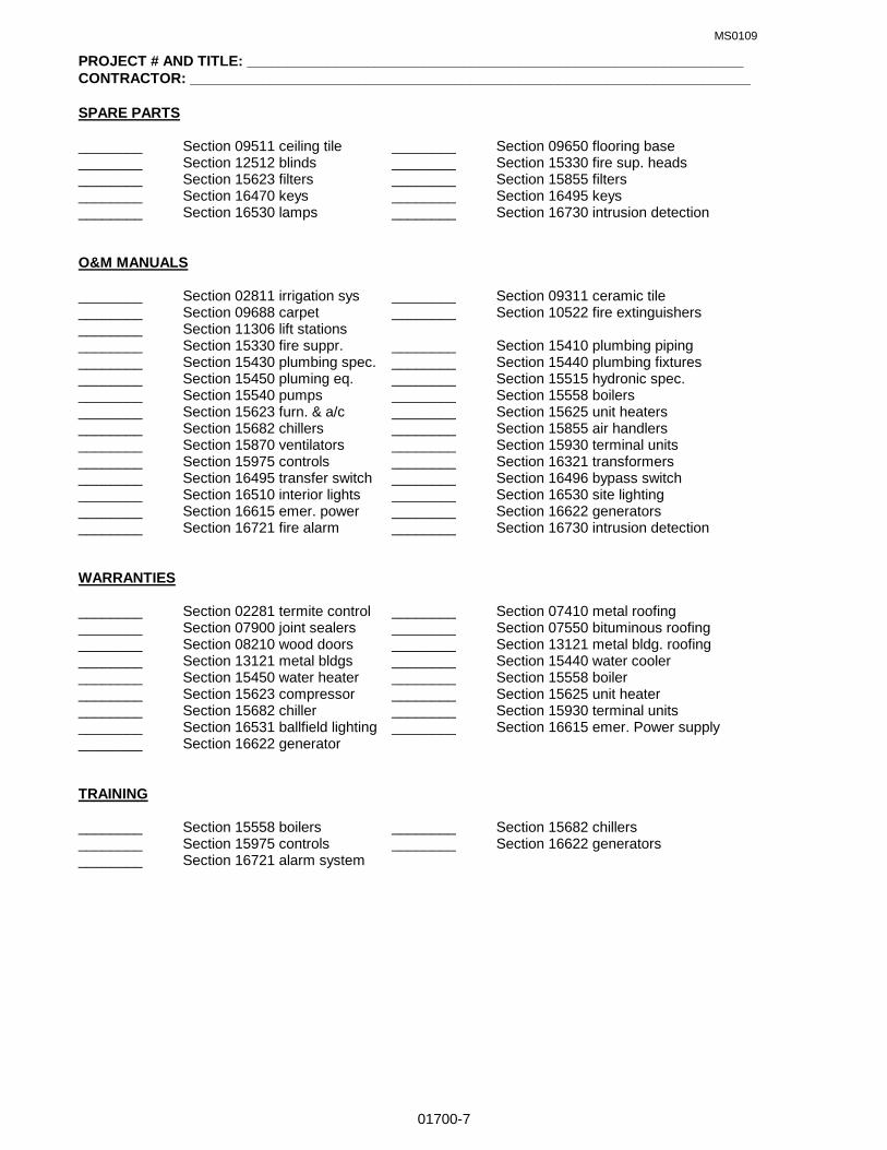
MS0109
01700-7
PROJECT # AND TITLE: ______________________________________________________________ CONTRACTOR: ______________________________________________________________________ SPARE PARTS ________ Section 09511 ceiling tile ________ Section 09650 flooring base ________ Section 12512 blinds ________ Section 15330 fire sup. heads ________ Section 15623 filters ________ Section 15855 filters ________ Section 16470 keys ________ Section 16495 keys ________ Section 16530 lamps ________ Section 16730 intrusion detection O&M MANUALS ________ Section 02811 irrigation sys ________ Section 09311 ceramic tile ________ Section 09688 carpet ________ Section 10522 fire extinguishers ________ Section 11306 lift stations ________ Section 15330 fire suppr. ________ Section 15410 plumbing piping ________ Section 15430 plumbing spec. ________ Section 15440 plumbing fixtures ________ Section 15450 pluming eq. ________ Section 15515 hydronic spec. ________ Section 15540 pumps ________ Section 15558 boilers ________ Section 15623 furn. & a/c ________ Section 15625 unit heaters ________ Section 15682 chillers ________ Section 15855 air handlers ________ Section 15870 ventilators ________ Section 15930 terminal units ________ Section 15975 controls ________ Section 16321 transformers ________ Section 16495 transfer switch ________ Section 16496 bypass switch ________ Section 16510 interior lights ________ Section 16530 site lighting ________ Section 16615 emer. power ________ Section 16622 generators ________ Section 16721 fire alarm ________ Section 16730 intrusion detection WARRANTIES ________ Section 02281 termite control ________ Section 07410 metal roofing ________ Section 07900 joint sealers ________ Section 07550 bituminous roofing ________ Section 08210 wood doors ________ Section 13121 metal bldg. roofing ________ Section 13121 metal bldgs ________ Section 15440 water cooler ________ Section 15450 water heater ________ Section 15558 boiler ________ Section 15623 compressor ________ Section 15625 unit heater ________ Section 15682 chiller ________ Section 15930 terminal units ________ Section 16531 ballfield lighting ________ Section 16615 emer. Power supply ________ Section 16622 generator TRAINING ________ Section 15558 boilers ________ Section 15682 chillers ________ Section 15975 controls ________ Section 16622 generators ________ Section 16721 alarm system

MS0109
01700-8
PROJECT # AND TITLE: ______________________________________________________________ CONTRACTOR: ______________________________________________________________________ TESTING ________ Section 02223 backfill ________ Section 02225 trenching ________ Section 02680 paving ________ Section 02811 irrigation sys ________ Section 03300 concrete ________ Section 04100 mortar ________ Section 11306 lift stations ________ Section 15330 fire suppression ________ Section 15410 plumbing piping ________ Section 15481 compressed air ________ Section 15510 hydronic piping ________ Section 15558 boilers ________ Section 15682 chillers ________ Section 15780 heat pumps ________ Section 15780 OA Units ________ Section 15890 ductwork ________ Section 15975 controls ________ Section 16121 med-voltage cable ________ Section 16141 wiring devices ________ Section 16170 grounding ________ Section 16622 generators ________ Section 16721 alarm system ________ Section 16730 detection sys ________ Section 16741 LAN systems

MS0109
01700-9
P R O J E C T W A R R A N T Y F O R M
BUILDING NUMBER & STREET ADDRESS: ____________________________________________________
PROJECT NUMBER & TITLE: ____________________________________________________ CONTRACT NUMBER: _____________________________________________________________________
PROJECT MANAGER & PHONE NO: _______________________________________________ CONTRACT SPECIALIST & PHONE NO. _______________________________________________________
DATE OF GOVERNMENT ACCEPTANCE: ______________________________________________________
GENERAL 0NE YEAR WARRANTY EXPIRATION DATE: __________________________________________
ONE YEAR WARRANTY INPSECTION DATE (30 days prior to expiration)___________________________
BRIEF DESCRIPTION OF WORK: ____________________________________________________________
_________________________________________________________________________________________
_________________________________________________________________________________________
_________________________________________________________________________________________
_________________________________________________________________________________________
PRIME KTR, PHONE NO. & FAX NO. __________________________________________________________
HVAC SUBKTR, PHONE & FAX NO. __________________________________________________________
PLUMBING SUBKTR, PHONE & FAX NOS. _____________________________________________________
ELECTRICAL SUBKTR. PHONE & FAX NO'S ___________________________________________________
E X T E N D E D W A R R A N T I E S
SPEC. ITEM & WARRANTY - RESPONSIBLE PARTY (IES)
02281 Termite Treatment, 5 yrs, Prime ktr & installer
02811 Irrigation System, 2 yr, Prime ktr & subktr
04300 Masonry, 2 yr, Prime ktr & subktr
07410 Preformed Metal Roofing, general, 2 yr Prime ktr & subktr
Panel finish, 20 year, Manufacturer
Leaking, 20 yr, Manufacturer
07550 Modified Bitumen Roofing, 10 yr, Manufacturer
07660 Sheet Metal Flashing & Trim, finish 20 yr, Manufacturer
08330 Overhead Rolling Doors, one year plus warranty, Manufacturer
13121 Pre-Engineered Building Systems, general, 2 yr, Prime ktr & installer
Siding finish, 5 yr, Manufacturer
Panel finish, 20 yr, Manufacturer
Leaking, 20 yr, Manufacturer
15440 Plumbing, water cooler compressor, 5 yr, Manufacturer
15450 Plumbing, water heater tank, 6 yr, Manufacturer
15481 Compressed Air Systems, air compressor, 5 yr, Manufacturer
15558 Finned Water Tube Boilers, boiler heat exchanger, 5 yr, Manufacturer

MS0109
01700-10
E X T E N D E D W A R R A N T I E S, continued.
SPEC. ITEM & WARRANTY - RESPONSIBLE PARTY (IES)
15623 Forced Air Furnaces &Split System Air Conditioning,
5 yr compressor, 10 yr heat exchanger, Manufacturer
15625 Fuel Fired Unit Heaters, unit heat exchanger, 5 yr, Manufacturer
15682 Air Cooled Water Chillers, 5 yr, Manufacturer
16531 Ballfield Lighting, 5 yr, Manufacturer
16615 Emergency Power Supply, 5 yr, Manufacturer
G E N E R A L I N F O R M A T I O N
SPEC ITEM DESCRIPTION; MANUFACTURER, SPEC #, STYLE, TYPE, COLOR, ETC.
04300 Brick, __________________________________________________________________________
04300 Concrete Masonry _______________________________________________________________
04300 Glass Masonry __________________________________________________________________
06410 Custom Casework _______________________________________________________________
07230 EIFS ___________________________________________________________________________
07410 Prefrmd. Roofing & Access. _______________________________________________________
07550 Modif'd Bitumen Memb. Roofing ___________________________________________________
08111 Steel Doors & Frames ____________________________________________________________
08210 Wood Doors ____________________________________________________________________
08410 Alum. Entry & Storefront __________________________________________________________
08520 Alum. Windows, Oper. & Fixed _____________________________________________________
08720 Door H'dware Latchsets __________________________________________________________
Locksets _______________________________________________________________________
Closers ________________________________________________________________________
Exit Devices ____________________________________________________________________
09311 Cer. Tile Floor & Wall _____________________________________________________________
09511 Susp. Acoust. Ceiling ____________________________________________________________
09650 Resilient Floor __________________________________________________________________
09688 Carpet _________________________________________________________________________
09900 Painting ________________________________________________________________________
10165 Plas. Lam. Toil. Part's ____________________________________________________________
10260 Bumper, Corner & Wall Prot. ______________________________________________________
10440 Interior Signage _________________________________________________________________
10800 Toil. & Bath Access. _____________________________________________________________
12512 Mini & Vert. Blinds _______________________________________________________________
13121 Pre-Engr. Bldg. Systems __________________________________________________________
16321 Distribution Transfmers. __________________________________________________________
16470 Panelboards ____________________________________________________________________
16475 Load Centers ___________________________________________________________________

MS0109
01700-11
G E N E R A L I N F O R M A T I O N, continued.
SPEC ITEM DESCRIPTION; MANUFACTURER, SPEC #, STYLE, TYPE, COLOR, ETC.
16495 Transfer Switch _________________________________________________________________
16496 By-pass Isolation Switch _________________________________________________________
16510 Interior Luminaires ______________________________________________________________
16530 Site Lighting ____________________________________________________________________
16622 Pkg. Engine Generator Syst. ______________________________________________________
16721 Fire Detect. & Alarm Syst. _________________________________________________________
16730 Intrusion Detect. Syst. ____________________________________________________________
I N S T R U C T I O N S
1. The prime contractor shall complete this form and provide it with the close out documentation.
2. Extended warranties; Provide name, phone and fax number for the responsible party (ies).
3. General Information; Provide name, phone and fax number, and pertinent information indicated for each item
listed.
4. It may not be required to use all of the items listed under Extended Warranties and General Information, in the
construction of this project. Should this occur, simply line through the item to indicate it was not used on this
project.
____________________________________ _____________________________________
Prime Contractor (See note below) Date
____________________________________ _____________________________________
Mailing Address City, State and Zip Code
____________________________________ _____________________________________
Phone Number Fax Number
____________________________________
E-mail Address
If prime contractor is a corporation, affix the corporate seal below and provide signature of responsible party who
can legally obligate the corporation.

MS0109
02070-1
SECTION 02070: SELECTIVE DEMOLITION PART 1 GENERAL 1.01 RELATED SPECIFICATION SECTION: A. Section 01000 – GENERAL REQUIREMENTS 1.02 SUMMARY A. Provide all demolition as required by the Contract Documents. 1. Demolish interior and exterior portions of structures including but not limited to, walls, partitions,
windows, doors, roofing, paving/curb/guttering, site furniture, shrubs, trees, interior finishes, etc., and associated components.
2. Demolish plumbing, mechanical, and electrical equipment and associated components 3. Demolished materials shall become the property of the Contractor unless otherwise noted on the
Drawings or in the Specifications. 4. Remove and dispose of demolished materials at a legally approved dumpsite off base. 5. Notify Contracting Officer prior to shut-off of existing utilities. Cap off utilities that are to remain in use. 6. Where fasteners, bolts, piping, wiring, ductwork and/or equipment that is/are to be removed are
attached to or pass through walls, floors, ceilings or roofs, the Contractor shall patch all holes or openings under 1(one) square foot in size to match adjacent construction. Patch holes or openings in fire rated walls as required to maintain fire rating.
7. Existing fire suppression systems, fire detection systems, and intrusion systems must remain active unless approved by the Contracting Officer and the responsible agency (Fire Department/Security Forces). Required deactivation of systems, or portions thereof, during demolition/construction must be requested and approved 72 hours in advance. Contractor will be responsible for protection of premises during periods of deactivation. If necessary, provide temporary protection or services.
1.03 SUBMITTALS
A. Submit for approval selective demolition schedule, including schedule and methods for capping and continuing utility service, and clearing & grubbing schedule.
1.04 QUALITY ASSURANCE
A. Comply with governing codes and regulations. Use experienced workmen. 1.05 PROJECT CONDITIONS
A. Government personnel will not occupy areas of Work during demolition. PART 2 PRODUCTS (Not Used) PART 3 EXECUTION 3.01 DEMOLITION A. Do not damage building elements and improvements indicated to remain. Items of salvage value and not
included on schedule of salvage items to be returned to Government may be removed from structure. Storage or sale of items at Project site is prohibited.
B. Do not close or obstruct streets, walks, drives or other occupied or used spaces or facilities without the
written permission of the Contracting Officer and the authorities having jurisdiction. Do not interrupt utilities serving occupied or used facilities without the written permission of the Contracting Officer and authorities having jurisdiction. If necessary, provide temporary utilities
C. Cease operations if public safety or remaining structures are endangered. Perform temporary corrective
measures until operations can be continued properly. Complete closure of Air Force roads will not be authorized.
END OF SECTION

MS0109
02110-1
SECTION 02110: SITE CLEARING & GRADING PART 1 GENERAL 1.01 RELATED SPECIFICATION SECTIONS: A. Section 01000 – GENERAL REQUIREMENTS 1.02 SECTION INCLUDES A. Remove surface debris. B. Clear site of plant life and grass. C. Remove trees and shrubs. D. Remove root system of trees and shrubs.
E. Topsoil excavation. F. Site Grading 1.03 REGULATORY REQUIREMENTS A. Conform to applicable regulations and local ordinances for disposal of debris off Base.
B. Coordinate clearing Work with utility companies. 1.04 QUALITY ASSURANCE
A. Use skilled workman who are thoroughly trained and experienced in the necessary crafts and who are completely familiar with particular requirements of the Project and methods needed to accomplish same.
B. Use equipment adequate in size, capacity and numbers to accomplish the Work in a timely manner. PART 2 PRODUCTS 2.01 MATERIALS
A. Fill Materials, See Section 02223, Backfilling. B. Weed Killer: Provide a dry, free-flowing, dust free chemical compound, soluble in water, capable of
inhibiting the growth of weeds and other undesirable vegetation and approved for use on base by governmental agencies having jurisdiction.
C. Topsoil: Use stockpiled topsoil or provide topsoil consisting of friable, fertile soil of loamy character,
containing an amount of organic material normal to the region. Topsoil shall be capable of sustaining healthy plant life and be reasonably free from subsoils, roots, heavy or stiff clay, stones larger than 2” in greatest dimension, weeds, sticks, brush and other deleterious material.
PART 3 EXECUTION 3.01 PREPARATION
A. Verify that existing plant life designated to remain is tagged or identified. B. Examine the areas and conditions under which Work of this Section will be performed. Correct conditions
detrimental to the timely and proper completion of the Work. Do not proceed until unsatisfactory conditions are corrected.
3.02 PROTECTION
A. Protection of Person and Property. 1. Barricade open holes and depressions occurring as part of this Work and post warning lights or safety
flagging as required. 2. Operate warning lights during the hours from dusk to dawn each day and as otherwise required. 3. Protect structures, utilities, sidewalks, pavements, and other facilities from damage caused by
settlement, washout, and other hazards caused by the Work of this Section. B. Locate, identify, and protect utilities that are to remain and protect from damage. If active utility lines are
encountered that are not shown on the Drawings or otherwise made known to the Contractor, immediately notify the Contracting Officer and request instructions prior to proceeding with the Work.
C. If existing utility services are interrupted as a result of Work under this Section, immediately restore
service by repairing the damaged utility at no cost to the government.
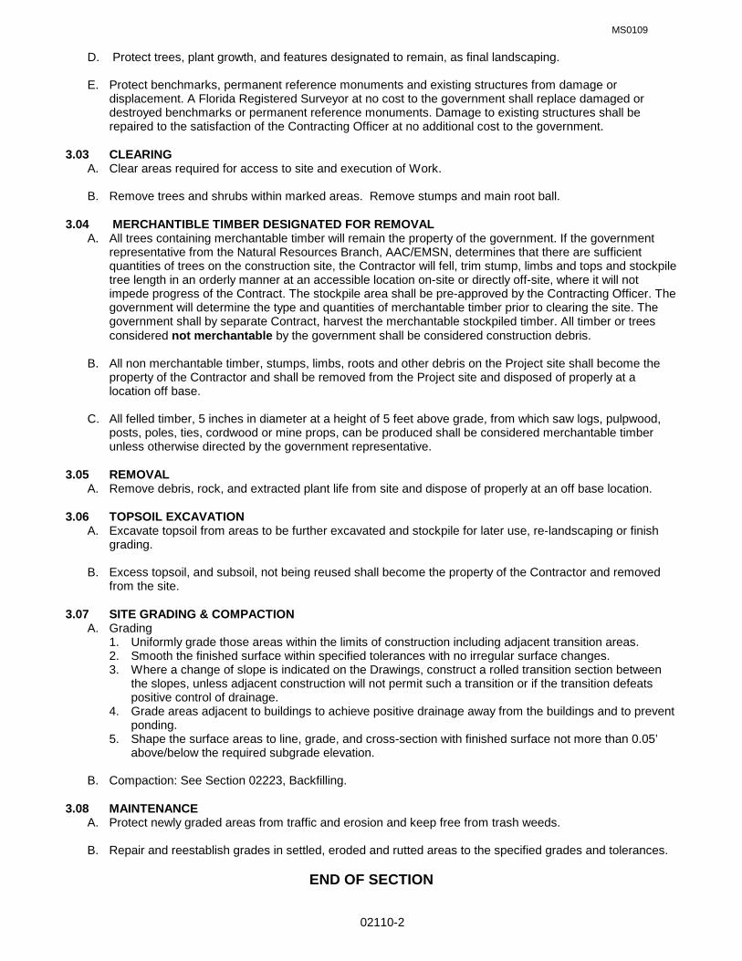
MS0109
02110-2
D. Protect trees, plant growth, and features designated to remain, as final landscaping.
E. Protect benchmarks, permanent reference monuments and existing structures from damage or displacement. A Florida Registered Surveyor at no cost to the government shall replace damaged or destroyed benchmarks or permanent reference monuments. Damage to existing structures shall be repaired to the satisfaction of the Contracting Officer at no additional cost to the government.
3.03 CLEARING A. Clear areas required for access to site and execution of Work. B. Remove trees and shrubs within marked areas. Remove stumps and main root ball. 3.04 MERCHANTIBLE TIMBER DESIGNATED FOR REMOVAL A. All trees containing merchantable timber will remain the property of the government. If the government
representative from the Natural Resources Branch, AAC/EMSN, determines that there are sufficient quantities of trees on the construction site, the Contractor will fell, trim stump, limbs and tops and stockpile tree length in an orderly manner at an accessible location on-site or directly off-site, where it will not impede progress of the Contract. The stockpile area shall be pre-approved by the Contracting Officer. The government will determine the type and quantities of merchantable timber prior to clearing the site. The government shall by separate Contract, harvest the merchantable stockpiled timber. All timber or trees considered not merchantable by the government shall be considered construction debris.
B. All non merchantable timber, stumps, limbs, roots and other debris on the Project site shall become the
property of the Contractor and shall be removed from the Project site and disposed of properly at a location off base.
C. All felled timber, 5 inches in diameter at a height of 5 feet above grade, from which saw logs, pulpwood,
posts, poles, ties, cordwood or mine props, can be produced shall be considered merchantable timber unless otherwise directed by the government representative.
3.05 REMOVAL A. Remove debris, rock, and extracted plant life from site and dispose of properly at an off base location. 3.06 TOPSOIL EXCAVATION
A. Excavate topsoil from areas to be further excavated and stockpile for later use, re-landscaping or finish grading.
B. Excess topsoil, and subsoil, not being reused shall become the property of the Contractor and removed
from the site. 3.07 SITE GRADING & COMPACTION
A. Grading 1. Uniformly grade those areas within the limits of construction including adjacent transition areas. 2. Smooth the finished surface within specified tolerances with no irregular surface changes. 3. Where a change of slope is indicated on the Drawings, construct a rolled transition section between
the slopes, unless adjacent construction will not permit such a transition or if the transition defeats positive control of drainage.
4. Grade areas adjacent to buildings to achieve positive drainage away from the buildings and to prevent ponding.
5. Shape the surface areas to line, grade, and cross-section with finished surface not more than 0.05’ above/below the required subgrade elevation.
B. Compaction: See Section 02223, Backfilling.
3.08 MAINTENANCE
A. Protect newly graded areas from traffic and erosion and keep free from trash weeds. B. Repair and reestablish grades in settled, eroded and rutted areas to the specified grades and tolerances.
END OF SECTION

MS0109
02222-1
SECTION 02222 EXCAVATION AND TRENCHING FOR FOUNDATIONS, SLAB ON GRADE, AND UTILITY SYSTEMS
PART 1 - GENERAL 1.01 RELATED SPECIFICATION SECTIONS:
A. Section 01000 – GENERAL REQUIREMENTS
1.02 SECTION INCLUDES: A. Protection of existing utilities. B. Protection of existing buildings and structures. C. Excavation for building foundations. D. Excavation for slabs-on-grade and paving. E. Excavation for utilities to 5 feet outside of building line. F. Excavation, trenching, and backfilling requirements for installation, maintenance, repair, and replacement of
storm sewer, sanitary sewer, and water distribution lines and appurtenances to the points of connection within 1.5 m (5 feet) of the buildings.
1.03 REFERENCES:
A. AMERICAN SOCIETY FOR TESTING AND MATERIALS (ASTM)
ASTM D 422 (1963; R 1990) Particle-Size Analysis of Soils
ASTM D 1556 (1990) Density and Unit Weight of Soil in Place by the Sand-Cone Method
ASTM D 698 (1991) Laboratory Compaction Characteristics of Soil Using Standard Method
ASTM D 2167 (1984; R 1990) Density and Unit Weight of Soil in Place by the Rubber Balloon Method
ASTM D 2487 (1992) Classification of Soils for Engineering Purposes (Unified Soil Classification System)
ASTM D 2922 (1991) Density of Soil and Soil-Aggregate in Place by Nuclear Methods (Shallow Depth)
ASTM D 3017 (1988) Water Content of Soil and Rock in Place by Nuclear Methods (Shallow Depth) 1.04 DEFINITIONS
A. Degree of Compaction shall be expressed as a percentage of the maximum density obtained by the test procedure presented in ASTM D 698.
1.05 SUBMITTALS The following shall be submitted in accordance with Section 01300 - Submittals.
A. Field Density Test Reports.
B. Backfill Material Test Reports. 1.06 COMPLETION OF WORK Should the Contractor fail to complete the work as scheduled, the Contracting Officer may limit the work which has been started but not completed to any such amount as deemed reasonable. No extension of time will be granted to the Contractor for not being permitted to start on new streets, alleys or rights-of-way to construction for this reason. PART 2 - PRODUCTS 2.01 MATERIALS
A. Satisfactory Materials shall consist of any material classified by ASTM D 2487 as GW, GP, and SW.

MS0109
02222-2
B. Unsatisfactory Materials: Unsatisfactory materials shall be materials that do not comply with the requirements for satisfactory materials. Unsatisfactory materials include, but are not limited to those materials containing roots and other organic matter, trash, debris, frozen materials and stones larger than 75 mm (3 inches), and materials classified in ASTM D 2487, as PT, OH, and OL. Unsatisfactory materials also include man-made fills, refuse, or backfills from previous construction.
C. Cohesionless and Cohesive Materials:
1. Cohesionless materials shall include materials classified in ASTM D 2487 as GW, GP, SW, and SP. Materials classified as GM and SM will be identified as cohesionless only when the fines are nonplastic.
2. Cohesive materials include materials classified in ASTM D 2487 as GC, SC, CL, MH, and CH.
D. Unyielding Material: Unyielding material shall consist of rock and gravelly soils with stones greater than 75
mm (3 inches) in any dimension or as defined by the pipe manufacturer, whichever is smaller.
E. Unstable Material shall consist of materials too wet to properly support the utility pipe, conduit, or appurtenant structure.
F. Select Granular Material: Select granular material shall consist of well-graded sand, gravel, crushed gravel,
crushed stone or crushed slag composed of hard, tough and durable particles, and shall contain not more than 10 percent by weight of material passing a 0.075 mm (No. 200) mesh sieve and no less than 95 percent by weight passing the 25 mm (1-inch) sieve. The maximum allowable aggregate size shall be 100 mm (1 inch per foot) of pipe diameter, or the maximum size recommended by the pipe manufacturer, whichever is smaller.
G. Initial Backfill Material shall consist of select granular material or satisfactory materials free from rocks 2 mm
(3/4 inch) or larger in any dimension or free from rocks of such size as recommended by the pipe manufacturer, whichever is smaller.
H. Plastic Marking Tape: Plastic marking tape shall be acid and alkali-resistant polyethylene film, 152 mm (6 inches) wide with minimum thickness of 0.102 mm (0.004 inch). Tape shall have a minimum strength of 12.1 MPa (1750 psi) lengthwise and 10.3 MPa (1500 psi) crosswise. The tape shall be manufactured with integral wires, foil backing or other means to enable detection by metal detector when the tape is buried up to 3 feet deep. The tape shall be of a type specifically manufactured for marking and locating underground utilities. The metallic core of the tape shall be encased in a protective jacket or provided with other means to protect it from corrosion. Tape color shall be as specified in Table 1 and shall bear a continuous printed inscription describing the specific utility.
Table 1. Tape Color
Red: Electric Yellow: Gas, Oil, Dangerous Materials Orange: Telephone, Telegraph, Television, Police, and Fire Communications Blue: Water Systems Green: Sewer Systems
PART 3 - EXECUTION 3.01 PREPERATION
A. Verify the existence and location of underground utilities along the route of work. Omission from, or inclusion of, utility locations on the Drawings is not to be considered as the nonexistence of, or a definite location of, existing underground utilities. 1. Identify required lines, levels, contours, and datum. 2. Identify known underground, above ground and aerial utilities. Stake and flag locations. 3. Protect above and below grade utilities which are to remain.

MS0109
02222-3
4. Protect plants, shrubs, trees, lawns, and other features remaining as a portion of final landscaping. 5. Protect benchmarks, existing structures, fences, sidewalks, paving, and curbs from excavation
equipment and vehicular traffic. 3.02 PROTECTION
A. Existing Utilities: 1. Protect existing known utilities from damage due to work required under the scope of this contract. Any
damage to utilities will be repaired at the expense of the Contractor. 2. Before beginning trenching operations, obtain an Air Force Form 103, Civil Engineering Work
Clearance Permit for any underground or overhead utilities which may be on, or in close proximity to, the trenching areas.
B. Existing Buildings and Structures:
1. Guard against, and be responsible for, any movement, settlement, or collapse of adjacent buildings, sidewalks, structures, and underground and aboveground utilities. Repair damage done to the Base's property or any other property, on or off the premises, by reason of required work. Adequately brace walls during backfilling and compacting operations.
2. Items to be Relocated: Exercise the greatest possible care when items are scheduled for relocation. Use only skilled labor in the appropriate crafts. Identify items to be relocated, store and protect as directed.
C. Provide for surface drainage during the period of construction in a manner that protects trenches and
adjacent areas. Take precautions and temporary measures, such as temporary seeding, to prevent damage from erosion of freshly graded areas. This applies to damage of newly graded areas within construction limits and damage to adjacent properties by eroded materials.
3.03 EXCAVATION
A. General: 1. Excavation shall be performed to the lines and grades indicated. 2. During excavation, material satisfactory for backfilling shall be stockpiled in an orderly manner at a
distance from the banks of the trench equal to 1/2 the depth of the excavation, but in no instance closer than (2 feet).
3. Excavated material not required or not satisfactory for backfill shall be removed from the site. 4. Grading shall be done as may be necessary to prevent surface water from flowing into the excavation,
and any water accumulating therein, regardless of source, shall be removed to maintain the stability of the bottom and sides of the excavation. Continue to remove and dispose of water until utility lines, fittings, manholes, and other appurtenances are in place and sealed against the entrance of water. Water, earth, or any foreign materials shall not be allowed to enter the utility lines.
5. Unauthorized overexcavation shall be backfilled in accordance with section 02223, paragraphs 3.05 & 3.07 at no additional cost to the Government.
6. Correct unauthorized excavation at no extra cost to Government. 7. Remove unused excavated material from site in accordance with the following:
a. The contractor shall notify the Contracting Officer of the estimated or actual quantity of excess satisfactory soil, defined as those complying with ASTM D2487soil classification groups GW, GP, GM, SM, SW, and SP. The excess soil shall be removed and disposed of off base by the Contractor.
b. All unsatisfactory soil, as defined as those complying with ASTM D2487 soil classification groups GC, SC, ML, MH, CL, CH, OL, OH, and PT, shall be the Contractor's responsibility for disposal off base.
B. Trench Excavation: The trench shall be excavated as recommended by the manufacturer of the pipe to be installed. Trench walls below the top of the pipe shall be sloped, or made vertical, and of such width as recommended in the manufacturer’s installation manual. Where no manufacturer’s installation manual is available, trench walls shall be made vertical. Trench walls more than five feet high shall be shored, cut back to a stable slope, or provided with equivalent means of protection for employees who may be exposed

MS0109
02222-4
to moving ground or cave in. Trench walls which are cut back shall be excavated to at least the angle of repose of the soil. Special attention shall be given to slopes which may be adversely affected by weather or moisture content. The trench width below the top of pipe shall not exceed 24 inches plus pipe outside diameter (O.D.) for pipes of less than 24 inches inside diameter and shall not exceed 36 inches plus pipe outside diameter for sizes larger than 24 inches inside diameter. Where recommended trench widths are exceeded, redesign, stronger pipe, or special installation procedures shall be utilized by the Contractor. The cost of redesign, stronger pipe, or special installation procedures shall be borne by the Contractor without any additional cost to the Government.
1. Bottom Preparation: The bottoms of trenches shall be accurately graded to provide uniform bearing
and support for the bottom quadrant of each section of the pipe. Bell holes shall be excavated to the necessary size at each joint or coupling to eliminate point bearing. Stones of 1.5 inches or greater in any dimension, or as recommended by the pipe manufacturer, whichever is smaller, shall be removed to avoid point bearing.
2. Removal of Unyielding Material: Where unyielding material is encountered in the bottom of the trench, such material shall be removed a minimum of 4 inches below the required grade and replaced with suitable materials as provided in section 02223 ,paragraphs 3.05 & 3.07.
3. Removal of Unstable Material: Where unstable material in encountered in the bottom of the trench, such material shall be removed to the depth directed and replaced to the proper grade with Type “D” as provided in Section 02223, paragraph 2.01.D. When removal of unstable material is required due to the fault or neglect of the contractor in his performance of the work, the resulting material shall be excavated and replaced by the Contractor without additional cost to the Government.
4. Jacking, Boring, and Tunneling: Unless otherwise indicated, excavation shall be by open cut except that sections of a trench may be jacked, bored, or tunneled if, in the opinion of the Contracting Officer, the pipe, or duct can be safely and properly installed and backfill can be properly compacted in such sections.
C. Excavation for Appurtenances: Excavation for manholes, catch-basins, inlets, or similar structures shall be
sufficient to leave at least 12 inches clear between the outer structure surfaces and the face of the excavation or support members. Removal of unstable material shall be as specified above. When concrete or masonry is to be placed in an excavated area special care shall be taken not to disturb the bottom of the excavation. Excavation to the final grade level shall not be made until just before the concrete or masonry is to be placed.
3.04 SPECIAL REQUIREMENTS: Special requirements for both excavation and backfill relating to the specific utilities are as follows:
A. Water Lines: Trenches shall be of a depth to provide a minimum cover of 3-1/2 feet from the existing ground surface, or from the indicated finished grade, whichever is lower, to the top of the pipe.
B. Plastic Marking Tape: Warning tapes shall be installed directly above the pipe, at the depth of 12-18 inches
below finished grade unless otherwise shown. 3.05 TESTING: Testing shall be the responsibility of the Contractor and shall be performed at no additional cost to the Government.
A. Testing Facilities: Tests shall be performed by an approved commercial testing laboratory or may be tested by facilities furnished by the Contractor. No work requiring testing will be permitted until the facilities have been inspected and approved by the Contracting Officer. The first inspection shall be at the expense of the Government. Cost incurred for any subsequent inspection required because of failure of the first inspection will be charged to the Contractor.
B. Testing of Backfill Materials: Characteristics of backfill materials shall be determined in accordance with
particle size analysis of soils ASTM D 422 and moisture-density relations of soils ASTM D 1557. A minimum of one particle size analysis and one moisture-density relation test shall be performed on each different type of material used for bedding and backfill.
MS0109
02222-5
C. Field Density Tests: Tests shall be performed in sufficient numbers to ensure that the specified density is being obtained. A minimum of one field density test per lift of backfill for every 500 feet of installation shall be performed. One moisture density relationship shall be determined for every 1500 cubic yards of material used. Field in-place density shall be determined in accordance with ASTM D 1556 or ASTM D 2922. When ASTM D 2922 is used, the calibration curves shall be checked and adjusted using the sand cone method as described in paragraph Calibration of the ASTM publication. ASTM D 2922 results in a wet unit weight of soil and when using this method, ASTM D 3017 shall be used to determine the moisture content of the soil. The calibration curves furnished with the moisture gauges shall be checked along with the density calibration checks as described in ASTM D 3017. The calibration checks of both the density and moisture gauges shall be made at the beginning of a job, on each different type of material encountered, at intervals as directed by the Contracting Officer. Copies of calibration curves, results of calibration tests, and field and laboratory density tests shall be furnished to the Contracting Officer. Trenches improperly compacted shall be reopened to the depth directed, then refilled and compacted to the density specified at no additional cost to the Government.
D. Displacement of Sewers: After other required tests have been performed and the trench backfill compacted
to 2 feet above the top of the pipe, the pipe shall be inspected to determine whether significant displacement has occurred. This inspection shall be conducted in the presence of the Contracting Officer’s representative. Pipe sizes larger than (36 inches) shall be entered and examined, while smaller diameter pipe shall be inspected by shining a light or laser between manholes or manhole locations, or by the use of television cameras passed through the pipe. If, in the judgment of the Contracting Officer, the interior of the pipe shows poor alignment or any other defects that would cause improper functioning of the system, the defects shall be remedied as directed at no additional cost to the Government.
3.06 SETTLEMENT OCCURRING WITHIN THE GUARANTEE PERIOD: Regardless of the type of compaction or settlement methods used, should settlement occur, refill, compact, and smooth off trenches until made to conform to the ground surface. Correct settlement under pavements and sidewalks as required. 3.07 GRADING: Grade to a finish ordinarily obtained from a blade grader, without abrupt changes in grade or holes that will hold water so that effective drainage is secured at all times. Maintain roadways in an acceptable condition at all times until final acceptance. 3.08 FIELD QUALITY CONTROL A. Field inspection will be performed under provisions of Section 01410. B. Provide for visual inspection of bearing surfaces. 3.09 SPECIAL PROVISIONS A. Maximum length of open trench at any time shall not exceed 165 linear meters (500 linear feet) unless approved otherwise. When approved, the Contractor may upon request, conduct pipe laying activities at more than one separate location; with the restrictions on open trenches applying to each location.
B. Move minor structures and restore temporary openings in fences to their original condition. Stockpile and reset, in original locations, any culverts, pipes, cables, or minor structures which are moved. Determine actual condition as to structures and miscellaneous obstacles to move for construction purposes. Removal and placement of these items shall be considered as part of the Contractor's obligation, and no additional payment shall be made.
C. Make open cuts or excavations in sidewalks without additional compensation. Remove concrete from joint
to joint wherever the trench crosses a sidewalk or sawcut for asphalt driveways, walkways, and jogging paths. After the pipe is in place and backfilled to the specified density the Contractor shall, at his own expense, replace or reconstruct sidewalks, walkways, and driveways with like materials and restore to the original condition in a manner satisfactory to the Contracting Officer. All installations under pavements and slabs will be accomplished by directional boring to a minimum of five feet beyond the pavement or slab
MS0109
02222-6
edge. Asphalt settlement or concrete breakage over trenches shall be repaired as directed by the Contracting Officer.
D. The Contractor shall maintain all the streets he/she is working on until acceptance of the work. Maintenance
shall include grading the streets if they become bumpy or rough and the spraying of water on the streets to keep the dust down.
E. Re-sod areas disturbed by grading or construction.
F. Cleanup shall proceed directly behind backfilling to accommodate the return to normal conditions. The
amount of work on which complete cleanup has not been accomplished shall be limited to 330 linear meters (1,000 linear feet) for the entire job should the Contractor fail to diligently pursue job cleanup.
END OF SECTION

MS0109
02223-1
SECTION 02223: BACKFILLING & COMPACTION PART 1 GENERAL 1.01 RELATED SPECIFICATION SECTIONS: A. Section 01000 – GENERAL REQUIREMENTS 1.02 SECTION INCLUDES: A. Building perimeter backfilling. B. Site filling and backfilling. C. Fill under slabs-on-grade and paving. D. Consolidation and compaction. E. Fill for over-excavation. F. Sheet vapor retardant and fill. 1.03 REFERENCES: A. ANSI/ASTM C136 - Method for Sieve Analysis of Fine and Coarse Aggregates. B. ANSI/ASTM D698 - Test Methods for Moisture-Density Relations of Soils and Soil-Aggregate Mixtures,
Using 5.5 lb (2.49 kg) Rammer and 12 inch (304.8 mm) Drop. C. ANSI/ASTM D1556 - Test Method for Density of Soil in Place by the Sand-Cone Method. D. ANSI/ASTM D2922 - Test Methods for Density of Soil and Soil-Aggregate in Place by Nuclear Methods
(Shallow Depth). E. State of Florida Department of Transportation (DOT), Standard Specifications for Road and Bridge Construction (SSRBC), 1999 or later edition. 1.04 SUBMITTALS: A. Submit under provisions of Section 01300. B. Samples: Submit 10 lb. sample of each type of fill to testing laboratory, in airtight containers. PART 2 PRODUCTS 2.01 FILL MATERIALS: A. Type A - Crushed Stone: Pit run or river washed natural stone; free of shale, clay, friable material, sand,
debris; graded in accordance with ANSI/ASTM C136 within the following limits: Sieve Size Percent Passing 2 inches (5O mm) 100 One inch (25 mm) 95 3/4 inch (19 mm) 95 to 100 5/8 inch (16 mm) 75 to 100 3/8 inch (09 mm) 55 to 85 No. 4 35 to 60 B. Type B - Pea Gravel: Natural stone; washed, free of clay, shale, organic matter; graded in accordance
with ANSI/ASTM C136, to the following: 1. Minimum Size: 1/4 inch. 2. Maximum Size: 5/8 inch. C. Type C - Sand: Natural river or bank sand; free of silt, clay, loam, friable or soluble materials, or organic
matter; graded in accordance with ANSI/ASTM C136, within the following limits:
MS0109
02223-2
Sieve Size Percent Passing No. 4 100 No. 14 10 to 100 No. 50 5 to 90 No. 100 4 to 30 No. 200 0 D. Type D - Structural Fill: 1. Earth for structural fill shall consist of material containing no more than 10 percent by weight finer than
No. 200 US Standard Sieve and shall be inorganic and conform to the following properties: a. Liquid Limit = 30 maximum b. Plasticity Index = 20 maximum c. Dry Unit Weight = 100 pcf minimum 2. Gravel shall consist of crushed stone or gravel. Size and gradation shall be as specified hereinbelow:
Total Percent Passing Sieve (By Weight) Square Sieve 1-1/2 1 3/4 1/2 3/8 #4 #8 Top 100 100 100 90- 40- 0- 0- One-Third 100 70 10 5 (Size #7) Bottom 100 95- 90- 25- 20- 0- 0- Two-Thirds 100 100 60 55 10 5 3. Material, which does not conform to the above classifications, may be used as Site Fill material, only
outside building and pavement lines, provided Site Fill specifications are met. E. Subsoil: Reused or imported, free of gravel larger than 3-inch size, debris, and organic material. F. Concrete: Lean concrete with a compressive strength of 1,000 psi. PART 3 EXECUTION 3.01 EXAMINATION: A. Verify fill materials to be reused are acceptable. B. Verify foundation perimeter drainage installation has been inspected. 3.02 PREPARATION: A. Generally, compact subgrade to density requirements for subsequent backfill materials. B. Cut out soft areas of subgrade not capable of insitu compaction. Backfill with Type A, B, C, or D fill and
compact to density equal to or greater than requirements for subsequent backfill material. C. Prior to placement of aggregate base course material at gravel or paved areas, compact subsoil to
98percent of its maximum dry density in accordance with ANSI/ASTM D698. 3.03 BACKFILLING: A. Backfill areas to contours and elevations with unfrozen materials. B. Systematically backfill to allow maximum time for natural settlement. Do not backfill over porous, wet,
frozen or spongy subgrade surfaces. C. Granular Fill: Place and compact materials in continuous layers not exceeding 8 inches compacted depth. D. Soil Fill: Place and compact material in continuous layers not exceeding 8 inches compacted depth. E. Employ a placement method that does not disturb or damage utilities in trenches. F. Maintain optimum moisture content of backfill materials to attain required compaction density.
MS0109
02223-3
G. Slope grade away from building A minimum of 6-inches in 10 feet unless noted otherwise. H. Make grade changes gradual. Blend slope into level areas. I. Remove surplus backfill materials from site. J. Trench Backfill: Trenches shall be backfilled to the grade shown. The trench may be backfilled to 2 feet above the top of pipe prior to performing the required pressure tests. The joints and couplings shall be
left uncovered during the pressure test. The trench shall not be completely backfilled until all specified tests are performed.
3.04 TOLERANCES: A. Top surface of backfilling must be plus or minus one inch from required elevations. 3.05 FIELD QUALITY CONTROL: A. Field inspection and testing will be performed under provisions of Section 01410. B. Tests and analysis of fill material will be performed in accordance with ANSI/ASTM D698 and with Section
01410. C. Compaction testing will be performed in accordance with ANSI/ASTM Dl556, ANSI/ASTM D2922, and
ANSI/ASTM D698 and with Section 01410. D. If tests indicate work does not meet specified requirements, remove work, replace and retest at no cost to
Government. E. Moisture & Density tests shall be in accordance with applicable sections of the Florida Dept. of
Transportation Standard Specifications for the specific type of paving. 3.06 PROTECTION OF FINISHED WORK: A. Re-compact fills subjected to vehicular traffic. 3.07 COMPACTION SCHEDULE: A. Slab-On-Grade, Footings and Bottom of Trenches: 1. Type D fill, 8 inches thick below bottom of floor slab/footing/trench, compacted to 100 percent. 2. Cover with Type A fill, if called for on the drawings, 4 inches thick, compacted to 100 percent. 3. Frequency of Tests: a. Slab-On-Grade: One per 1000 square feet of slab area or fraction thereof for each lift. b. Footings and Bottom of Trenches: One per 50 linear feet or fraction thereof. B. Exterior Side of Foundation Walls and Under Grass Areas: 1. Subsoil or Type D fill, to 6" below finish grade, compacted to 95 percent. 2. Remainder of 6" fill with topsoil, Compacted to 90 percent. 3. Frequency of Tests: a. Exterior Areas: One per 1000 square feet or fraction thereof. C. Fill Under Asphalt Paving (Base): 1. Type A fill, minimum 6" inches thick below bottom of finish paving, compacted to 100 percent; or 2. Minimum 6 inches thick lean concrete to minimum compressive strength of 1,000 psi. 3. Frequency of Tests: a. Base Course: One per 1000 square feet or fraction thereof. END OF SECTION
CIVILIDIQ2006
02720-1
SECTION 02720 STORM-DRAINAGE SYSTEM PART 1 - GENERAL 1.01 SECTION INCLUDES: Requirements for storm drainage piping systems using concrete, clay, steel,
ductile iron, aluminum, polyvinyl chloride (PVC), and polyethylene (PE) pipe. 1.02 MEASUREMENT
A. Pipe Culverts and Storm Drains: The length of pipe installed will be measured along the centerlines of the pipe from end to end of pipe without deductions for diameter of manholes.
B. Manholes and Inlets: The quantity of manholes and inlets will be measured as the total number of
manholes and inlets of the various types of construction, complete with frames and gratings or covers and, where indicated, with fixed side-rail ladders, constructed to the depths shown on the drawings and listed in the bid schedule. The depth of manholes and inlets will be measured from the top of grating or cover to invert of outlet pipe).
C. Walls and headwalls will be measured as the number of walls and headwalls constructed in the
completed work.
D. Flared End Sections will be measured by the unit.
E. Sheeting and Bracing: Payment will be made for that sheeting and bracing ordered left in place based on the number of square meters (feet) of sheeting and bracing remaining below the surface of the ground.
F. Rock Excavation: Not included.
G. Backfill Replacing Unstable Material: The number of cubic meters (yards) of select granular material
required to replace unstable material for foundations under pipes or drainage structures, which will constitute full compensation for this backfill material, including removal and disposal of unstable material and all excavating, hauling, placing, compacting, and all incidentals necessary to complete the construction of the foundation satisfactorily.
1.03 REFERENCES
A. AMERICAN ASSOCIATION OF STATE HIGHWAY AND TRANSPORTATION OFFICIALS (AASHTO) 1. AASHTO-01 (1992) Standard Specifications for Highway Bridges 2. AASHTO M 167 (1989) Corrugated Steel Structural Plate, Zinc Coated, for Field Bolted Pipe 3. AASHTO M 190 (1980; Rev 1986) Bituminous Coated Corrugated Metal Culvert Pipe and Pipe
Arches 4. AASHTO M 198 (1975; Rev 1986) Joints for Circular Concrete Sewer and Culvert Pipe Using
Flexible Watertight Gaskets 5. AASHTO M 219 (1984) Aluminum Alloy Structural Plate for Field Bolted Conduits 6. AASHTO M 243 (1981; Rev 1986) Field Applied Coating of Corrugated Metal Structural Plate for
Pipe, Pipe-Arches, and Arches 7. AASHTO M 294 (1991I) Corrugated Polyethylene Pipe, 12 to 36-in. Diameter
B. AMERICAN CONCRETE INSTITUTE (ACI)
1. ACI 346 (1990; 346R-1990) Cast-in-Place Nonreinforced Concrete Pipe
C. AMERICAN RAILWAY ENGINEERING ASSOCIATION (AREA) 1. AREA-01 (1992) Manual for Railway Engineering (Fixed Properties)
D. AMERICAN SOCIETY FOR TESTING AND MATERIALS (ASTM)
1. ASTM A 48 (1983; R 1990) Gray Iron Castings 2. ASTM A 123 (1989a) Zinc (Hot-Dip Galvanized) Coatings on Iron and Steel Products 3. ASTM A 444 (1989) Steel Sheet, Zinc-Coated (Galvanized) by the Hot-Dip Process for Storm
Sewer and Drainage Pipe 4. ASTM A 536 (1984) Ductile Iron Castings

CIVILIDIQ2006
02720-2
5. ASTM A 716 (1986; R 1991) Ductile Iron Culvert Pipe 6. ASTM A 742 (1986) Steel Sheet, Metallic Coated and Polymer Precoated for Corrugated Steel
Pipe 7. ASTM A 760 (1991) Corrugated Steel Pipe, Metallic-Coated for Sewers and Drains 8. ASTM A 762 (1991) Corrugated Steel Pipe, Polymer Precoated for Sewers and Drains 9. ASTM A 798 (1988) Installing Factory-Made Corrugated Steel Pipe for Sewers and Other
Applications 10. ASTM A 807 (1988) Installing Corrugated Steel Structural Plate Pipe for Sewers and Other
Applications 11. ASTM A 849 (1990) Post-Applied Coatings, Pavings, and Linings for Corrugated Steel Sewer
and Drainage Pipe 12. ASTM B 26 (1992a) Aluminum-Alloy Sand Castings 13. ASTM B 745 (1992) Corrugated Aluminum Pipe for Sewers and Drains 14. ASTM C 12 (1991) Installing Vitrified Clay Pipe Lines 15. ASTM C 14 (1990) Concrete Sewer, Storm Drain, and Culvert Pipe 16. ASTM C 32 (1991) Sewer and Manhole Brick (Made from Clay or Shale) 17. ASTM C 55 (1985) Concrete Building Brick 18. ASTM C 62 (1991b) Building Brick (Solid Masonry Units Made from Clay or Shale) 19. ASTM C 76 (1990) Reinforced Concrete Culvert, Storm Drain, and Sewer Pipe 20. ASTM C 139 (1973; R 1989) Concrete Masonry Units for Construction of Catch Basins and
Manholes 21. ASTM C 231 (1991b) Air Content of Freshly Mixed Concrete by the Pressure Method 22. ASTM C 270 (1992) Mortar for Unit Masonry 23. ASTM C 425 (1991) Compression Joints for Vitrified Clay Pipe and Fittings 24. ASTM C 443 (1985a; R 1990) Joints for Circular Concrete Sewer and Culvert Pipe, Using
Rubber Gaskets 25. ASTM C 478 (1990b) Precast Reinforced Concrete Manhole Sections 26. ASTM C 506 (1990) Reinforced Concrete Arch Culvert, Storm Drain, and Sewer Pipe 27. ASTM C 507 (1990) Reinforced Concrete Elliptical Culvert, Storm Drain, and Sewer Pipe 28. ASTM C 655 (1991) Reinforced Concrete D-Load Culvert, Storm Drain, and Sewer Pipe 29. ASTM C 700 (1991) Vitrified Clay Pipe, Extra Strength, Standard Strength, and Perforated 30. ASTM C 789 (1990) Precast Reinforced Concrete Box Sections for Culverts, Storm Drains,
and Sewers 31. ASTM C 850 (1990) Precast Reinforced Concrete Box Sections for Culverts, Storm Drains,
and Sewers with Less than 2 Ft. of Cover Subjected to Highway Loadings 32. ASTM C 877 (1991) External Sealing Bands for Noncircular Concrete Sewer, Storm Drain, and
Culvert Pipe 33. ASTM D 1056 (1991) Flexible Cellular Materials - Sponge or Expanded Rubber 34. ASTM D 1171 (1986) Rubber Deterioration - Surface Ozone Cracking Outdoors or Chamber
(Triangular Specimens) 35. ASTM D 1557 (1991) Laboratory Compaction Characteristics of Soil Using Modified Effort
(56,000 ft-lb/cu.ft. (2,700 kN-m/cu.m.)) 36. ASTM D 1751 (1983; R 1991) Preformed Expansion Joint Filler for Concrete Paving and
Structural Construction (Nonextruding and Resilient Bituminous Types) 37. ASTM D 1752 (1984; R 1992) Preformed Sponge Rubber and Cork Expansion Joint Fillers for
Concrete Paving and Structural Construction 38. ASTM D 1784 (1990) Rigid Poly(Vinyl Chloride) (PVC) Compounds and Chlorinated Poly(Vinyl
Chloride) (CPVC) Compounds 39. ASTM D 2167 (1984; R 1990) Density and Unit Weight of Soil in Place by the Rubber Balloon
Method 40. ASTM D 2321 (1989) Underground Installation of Thermoplastic Pipe for Sewers and Other
Gravity-Flow Applications 41. ASTM D 2922 (1991) Density of Soil and Soil-Aggregate in Place by Nuclear Methods (Shallow
Depth) 42. ASTM D 3017 (1988) Water Content of Soil and Rock in Place by Nuclear Methods (Shallow
Depth) 43. ASTM D 3034 (1989) Type PSM Poly(Vinyl Chloride) (PVC) Sewer Pipe and Fittings 44. ASTM D 3212 (1989) Joints for Drain and Sewer Plastic Pipes Using Flexible Elastomeric Seals

CIVILIDIQ2006
02720-3
45. ASTM D 3350 (1984) Polyethylene Plastic Pipe and Fittings Materials 46. ASTM F 679 (1989) Poly(Vinyl Chloride) (PVC)Large-Diameter Plastic Gravity Sewer Pipe and
Fittings 47. ASTM F 714 (1990) Polyethylene (PE) Plastic Pipe (SDR-PR) Based on Outside Diameter 48. ASTM F 794 (1991) Poly(Vinyl Chloride) (PVC) Profile Gravity Sewer Pipe and Fittings Based
on Controlled Inside Diameter 49. ASTM F 894 (1990) Polyethylene (PE) Large Diameter Profile Wall Sewer and Drain Pipe 50. ASTM F 949 (1991a) Poly(Vinyl Chloride) (PVC) Corrugated Sewer Pipe with a Smooth
Interior and Fittings
E. FEDERAL SPECIFICATIONS (FS) 1. FS HH-G-156 (Rev D; Int Am 1) Gasket Material, General Purpose; Rubber Sheets, Strips, and
Special Shapes 2. FS SS-S-210 (Rev A; Reinstatement Notice) Sealing Compound, Preformed Plastic, for
Expansion Joints and Pipe Joints
F. FEDERAL TEST METHOD STANDARDS (FTM-STD) 1. FTM-STD 601 (Basic; Notice 7) Rubber: Sampling and Testing
1.04 SUBMITTALS: The following shall be submitted in accordance with Section 01300 - Submittals.
A. Pipe Placing Instructions: Printed copies of the manufacturer's recommendations for installation procedures of the material being placed, prior to installation.
B. Certificates: Certified copies of test reports demonstrating conformance to applicable pipe specifications,
before pipe is installed. Certification on the ability of frame and cover or gratings to carry the imposed live load.
C. As-Built Drawings: Submit as part of the as-built drawings in accordance with section 01700, “Contract
Closeout” 1. Record actual locations of piping systems including all appurtenances and invert elevations. 2. Use GPS (Latitudes and Longitudes, Degrees/Minutes/Seconds).
1.05 DELIVERY, STORAGE, AND HANDLING
A. Delivery and Storage: Materials delivered to site shall be inspected for damage, unloaded, and stored with a minimum of handling. Materials shall not be stored directly on the ground. The inside of pipes and fittings shall be kept free of dirt and debris. Gasket materials and plastic materials shall be protected from exposure to the direct sunlight over extended periods.
B. Handling: Materials shall be handled in such a manner as to insure delivery to the trench in sound,
undamaged condition. Pipe shall be carried to the trench, not dragged. PART 2 - PRODUCTS 2.01 PIPE FOR CULVERTS AND STORM DRAINS
A. Pipe for culverts and storm drains shall be of the sizes indicated and shall conform to the requirements specified.
B. Concrete Pipe:
1. Concrete Pipe shall conform to ASTM C 76, Class I. 2. Reinforced Arch Culvert and Storm Drainpipe shall conform to ASTM C 506, Class A-II. 3. Reinforced Elliptical Culvert and Storm Drainpipe shall conform to ASTM C 507.
a. Horizontal elliptical pipe shall be Class HE-A. b. Vertical elliptical pipe shall be Class VE-II.
4. Nonreinforced Pipe shall conform to ASTM C 14, Class 3.
C. Corrugated Steel Pipe: 1. Corrugated steel pipe shall conform to ASTM A 760, zinc coated of either:
a. Type I or II pipe with annular or helical corrugations.

CIVILIDIQ2006
02720-4
b. Type IA or IIA pipe with helical corrugations fabricated with a smooth steel liner of Type C precoated sheet with a polymeric coating on both sides of not less than 0.25 mm (0.010-inch) thick conforming to ASTM A 742.
c. Type IR or IIR pipe with helical corrugations.
2. Fully Bituminous Coated Corrugated Steel Pipe shall conform to AASHTO M 190 Type A and ASTM A 760 zinc coated pipe of either: a. Type I or II pipe with annular or helical corrugations. b. Type IA or IIA pipe with helical corrugations fabricated with a smooth steel liner of Type C
precoated sheet with a polymeric coating on both sides of not less than 0.25 mm (0.010-inch) thick conforming to ASTM A 742. Bituminous coating shall only be applied to the outside surface of the shell and the inside surface of the liner.
c. Type IR or IIR pipe with helical corrugations.
D. PVC Pipe: The pipe stiffness shall be greater than or equal to 735/D for cohesionless material pipe trench backfills and greater than or equal to 1240/D for cohesive material pipe trench backfills or installation in an embankment or fill. D is the pipe diameter in inches. 1. Type PSM PVC Pipe: Type PSM PVC Pipe shall conform to ASTM D 3034, cell class 13364-B with
fittings cell class 13343-C by ASTM D 1784, Type PSM, SDR 23.5. 2. Ribbed PVC Pipe shall conform to ASTM F 794 produced from PVC certified by the compounder as
meeting the requirements of ASTM D 1784, cell class 12454B Series 46. 3. Smooth Wall PVC Pipe shall conform to ASTM F 679 produced from PVC certified by the
compounder as meeting the requirements of ASTM D 1784, cell class 12454B. 4. Corrugated PVC Pipe shall conform to ASTM F 949 produced from PVC certified by the compounder
as meeting the requirements of ASTM D 1784, cell class 12454B.
E. PE Pipe: The pipe stiffness shall be greater than or equal to 1170/D for cohesionless material pipe trench backfills and greater than or equal to 1990/D for cohesive material pipe trench backfills or installation in an embankment or fill. D is the pipe diameter in inches. 1. Smooth Wall PE Pipe shall conform to ASTM F 714 produced from PE certified by the resin producer
as meeting the requirements of ASTM D 3350, cell class 335434C. 2. Corrugated PE Pipe shall conform to AASHTO M 294 produced from PE certified by the resin
producer as meeting the requirements of ASTM D 3350, cell class 315412C or 334433C. 3. Ribbed PE Pipe shall conform to ASTM F 894 produced from PE certified by the resin producer as
meeting the requirements of ASTM D 3350, cell class 334433C, RSC 160. 2.02 DRAINAGE STRUCTURES
A. Flared End Sections shall be of a standard design fabricated from zinc coated steel sheets meeting requirements of ASTM A 444.
B. Precast Reinforced Concrete Box
1. For highway loadings with 600 mm (2 feet) of cover or more or subjected to dead load only, ASTM C 789; for less than 600 mm (2 feet) of cover subjected to highway loading, ASTM C 850.
2.03 MISCELLANEOUS MATERIALS
A. Concrete: Unless otherwise specified, concrete and reinforced concrete shall conform to the requirements for 221 Mpa (3000 psi) concrete under Section 03300 - Concrete, Cast-in-Place. The concrete mixture shall have air content by volume of concrete, based on measurements made immediately after discharge from the mixer, of 5 to 7 percent when maximum size of coarse aggregate exceeds 37.5 mm (1-1/2 inches). Air content shall be determined in accordance with ASTM C 231. The concrete covering over steel reinforcing shall not be less than 25 mm (1 inch) thick for covers and not less than 40 mm (1-1/2 inches) thick for walls and flooring. Concrete covering deposited directly against the ground shall have a thickness of at least 75 mm (3 inches) between steel and ground. Expansion-joint filler material shall conform to ASTM D 1751, or ASTM D 1752, or shall be resin-impregnated fiberboard conforming to the physical requirements of ASTM D 1752.
B. Mortar for pipe joints, connections to other drainage structures, and brick or block construction shall
conform to ASTM C 270, Type M, except the maximum placement time shall be 1 hour. The quantity of water in the mixture shall be sufficient to produce a stiff workable mortar. Water shall be clean and free of

CIVILIDIQ2006
02720-5
harmful acids, alkalis, and organic impurities. The mortar shall be used within 30 minutes after the ingredients are mixed with water. The inside of the joint shall be wiped clean and finished smooth. The mortar head on the outside shall be protected from air and sun with a proper covering until satisfactorily cured.
C. Precast Concrete Segmental Blocks shall conform to ASTM C 139, not more than 200 mm (8 inches)
thick, not less than 200 mm (8 inches) long, and of such shape that joints can be sealed effectively and bonded with cement mortar.
D. Brick shall conform to ASTM C 62, Grade SW; ASTM C 55, Grade S-I or S-II; or ASTM C 32, Grade MS.
Mortar for jointing and plastering shall consist of one part portland cement and two parts fine sand. Lime may be added to the mortar in a quantity not more than 25 percent of the volume of cement. The joints shall be filled completely and shall be smooth and free from surplus mortar on the inside of the structure. Brick structures shall be plastered with 10 mm (1/2 inch) of mortar over the entire outside surface of the walls. For square or rectangular structures, brick shall be laid in stretcher courses with a header course every sixth course. For round structures, brick shall be laid radially with every sixth course a stretcher course.
E. Precast Reinforced Concrete Manholes: Precast reinforced concrete manholes shall conform to ASTM C
478. Joints between precast concrete risers and tops shall be made with flexible watertight, rubber-type gaskets meeting the requirements of paragraph JOINTS.
F. Prefabricated Corrugated Metal Manholes shall be of the type and design recommended by the
manufacturer. Manholes shall be complete with frames and cover, or frames and gratings.
G. Frame and Cover or Gratings: 1. Frame and cover or gratings shall be cast gray iron, ASTM A 48, Class 35B; cast ductile iron, ASTM
A 536, Grade 65-45-12; or cast aluminum, ASTM B 26, Alloy 356.0T6. 2. Weight, shape, size, and waterway openings for grates and curb inlets shall be as indicated on the
plans.
H. Joints: 1. Flexible Watertight Joints:
a. Materials: Flexible watertight joints shall be made with plastic or rubber-type gaskets for concrete pipe and with factory-fabricated resilient materials for clay pipe. The design of joints and the physical requirements for plastic gaskets shall conform to AASHTO M 198, and rubber-type gaskets shall conform to ASTM C 443. Factory-fabricated resilient joint materials shall conform to ASTM C 425. Gaskets shall have not more than one factory-fabricated splice, except that two factory-fabricated splices of the rubber-type gasket are permitted if the nominal diameter of the pipe being gasketed exceeds 1.35 m (54 inches).
b. Test Requirements: Watertight joints shall be tested and shall meet test requirements of paragraph HYDROSTATIC TEST ON WATERTIGHT JOINTS. Gaskets or jointing materials shall not swell more than 100 percent by volume when immersed in accordance with Method 6211 of FTM-STD 601 in immersion medium No. 3 for 70 hours at 100 degrees C (212 degrees F).) Certified copies of test results shall be delivered to the Contracting Officer before gaskets or jointing materials are installed. Alternate types of watertight joint may be furnished if specifically approved.
2. Preformed Plastic Sealing Compound shall conform to FS SS-S-210. 3. External Sealing Bands shall conform to ASTM C 877. 4. Flexible Watertight, Gasketed Joints:
a. Gaskets: When infiltration or exfiltration is a concern for pipe lines, the couplings may be required to have gaskets. The closed-cell expanded rubber gaskets shall be a continuous band approximately 178 mm (7 inches) wide and approximately 9.5 mm (3/8-inch) thick, meeting the requirements of ASTM D 1056, and shall have a quality retention rating of not less than 70 percent when tested for weather resistance by ozone chamber exposure, Method B of ASTM D 1171. Rubber O-ring gaskets shall be 20.6 mm (13/16 inch) inch in diameter for pipe diameters of 914 mm (36 inches) or smaller and 22.2 mm (7/8 inch) in diameter for larger pipe having 12.7 mm (1/2-inch) deep end corrugation. Rubber O-ring gaskets shall be 34.9 mm (1-3/8 inches) in diameter for pipe having 25 mm (1-inch) deep end corrugations. O-rings shall meet the

CIVILIDIQ2006
02720-6
requirements of AASHTO M 198 or ASTM C 443. Flexible plastic gaskets shall conform to requirements of AASHTO M 198, Type B.
b. Connecting Bands: Connecting bands shall be of the type, size and sheet thickness of band, and the size of angles, bolts, rods and lugs as indicated or where not indicated as specified in the applicable standards for specifications for the pipe. Exterior rivet heads in the longitudinal seam under the connecting band shall be countersunk or the rivets shall be omitted and the seam welded. Watertight joints shall be tested and shall meet the test requirements of paragraph HYDROSTATIC TEST ON WATERTIGHT JOINTS.
5. PVC or PE Plastic Pipes: Water tight joints shall be as recommended by the pipe manufacturer in accordance with the requirements of ASTM D 3212. Other joints shall be soil tight in accordance with AASHTO-01, Division II, Section 23.3.1.5.4.
6. Ductile Iron Pipe: Couplings and fittings shall be as recommended by the pipe manufacturer. 2.04 STEEL LADDER: A steel ladder shall be provided where the depth of the manhole exceeds 3.66 m (12
feet). These ladders will be not less than 406 mm (16 inches) in width, with 19 mm (3/4 inch) diameter rungs spaced 305 mm (12 inches) apart. The two stringers shall be a minimum 9.5 mm (3/8 inch) thick and 63.5 mm (2-1/2 inches) wide. Ladders and inserts shall be galvanized after fabrication in conformance with ASTM A 123.
2.05 DOWNSPOUT BOOTS: Boots used to connect exterior downspouts to the storm-drainage system shall
be of gray cast iron conforming to ASTM A 48, Class 30B or 35B. Shape and size shall be as indicated. 2.06 HYDROSTATIC TEST ON WATERTIGHT JOINTS
A. Concrete, PVC and PE Pipe: A hydrostatic test shall be made on the watertight joint types as required. Only one sample joint of each type needs testing; however, if the sample joint fails because of faulty design or workmanship, an additional sample joint may be tested. During the test period, gaskets or other jointing material shall be protected from extreme temperatures which might adversely affect the performance of such materials. Performance requirements for joints in reinforced and nonreinforced concrete pipe shall conform to AASHTO M 198 or ASTM C 443. Test requirements for joints in clay pipe shall conform to ASTM C 425. Test requirements for joints in PVC and PE plastic pipe shall conform to ASTM D 3212.
B. Corrugated Steel and Aluminum Pipe: A hydrostatic test shall be made on the watertight joint system or
coupling band type proposed. The moment strength required of the joint is expressed as 15 percent of the calculated moment capacity of the pipe on a transverse section remote from the joint by the AASHTO-01 (Division 2, Section F23). The pipe will be supported for the hydrostatic test so that the joint is located at the point which develops 15 percent of the moment capacity of the pipe based on the allowable span in meters (feet) for the pipe flowing full or 54,233 Newton meters (40,000 foot-pounds), whichever is less. Performance requirements shall be met at an internal hydrostatic pressure of 69 kPa (10 psi) for a 10 minute period for both annular corrugated metal pipe and helical corrugated metal pipe with factory reformed ends.
PART 3 - EXECUTION 3.01 EXCAVATION FOR PIPE CULVERTS, STORM DRAINS, AND DRAINAGE STRUCTURES
A. Excavation of trenches and for appurtenances and backfilling for culverts and storm drains shall be in accordance with the applicable portions of Section 02222 - Excavation, Trenching, And Backfilling For Utilities Systems and the requirements specified below.
B. Trenching: The width of trenches at any point below the top of the pipe shall be not greater than the
outside diameter of the pipe plus 36 inches to permit satisfactory jointing and thorough tamping of the bedding material under and around the pipe. Sheeting and bracing where required shall be placed within the trench width as specified. Care shall be taken not to overexcavate. Where trench widths are exceeded, redesign with a resultant increase in cost of stronger pipe or special installation procedures shall be necessary. Cost of this redesign and increased cost of pipe or installation shall be borne by the Contractor without additional cost to the Government.
C. Removal of Unstable Material: Where wet or otherwise unstable soil incapable of properly supporting the
pipe, as determined by the Contracting Officer, is unexpectedly encountered in the bottom of a trench,

CIVILIDIQ2006
02720-7
such material shall be removed to the depth required and replaced to the proper grade with select granular material, compacted as provided in paragraph BACKFILLING. When removal of unstable material is due to the fault or neglect of the Contractor in his performance of shoring and sheeting, water removal, or other specified requirements, such removal and replacement shall be performed at no additional cost to the government.
3.02 BEDDING
A. The bedding surface for the pipe shall provide a firm foundation of uniform density throughout the entire length of the pipe. When no bedding class is specified or detailed on the drawings, concrete pipe shall be bedded carefully in a soil foundation accurately shaped and rounded to conform to the lowest one-fourth of the outside portion of circular pipe or to the lower curved portion of pipe arch for the entire length of the pipe or pipe arch. When necessary, the bedding shall be tamped. Bell holes and depressions for joints shall be only of such length, depth, and width as required for properly making the particular type of joint. Bedding for clay pipe shall be as specified by ASTM C 12. Bedding for corrugated metal pipe and pipe arch shall be in accordance with ASTM A 798. It is not required to shape the bedding to the pipe geometry. However, for pipe arches, it is recommended to either shape the bedding to the relatively flat bottom arc or fine grade the foundation to a shallow V-shape. Bedding for corrugated structural plate pipe shall meet requirements of ASTM A 807. Bedding for ductile iron culvert pipe shall meet requirements of ASTM A 716. Bedding for PVC and PE pipe shall meet the requirements of ASTM D 2321 for Class I II and III materials.
3.03 PLACING PIPE
A. Each pipe shall be carefully examined before being laid, and defective or damaged pipe shall not be used. Pipelines shall be laid to the grades and alignment indicated. Proper facilities shall be provided for lowering sections of pipe into trenches. Lifting lugs in vertically elongated metal pipe shall be placed in the same vertical plane as the major axis of the pipe. Under no circumstances shall pipe be laid in water, and no pipe shall be laid when trench conditions or weather are unsuitable for such work. Diversion of drainage or dewatering of trenches during construction shall be provided as necessary. All pipe in place shall be inspected before backfilling, and those pipes damaged during placement shall be removed and replaced.
1. Concrete, Clay, PVC, Ribbed PVC and Ductile Iron Pipe: Laying shall proceed upgrade with spigot
ends of bell-and-spigot pipe and tongue ends of tongue-and-groove pipe pointing in the direction of the flow.
2. Elliptical and Elliptical Reinforced Concrete Pipe: Placement shall be so that the manufacturer's reference lines designating the top of the pipe will be within 5 degrees of a vertical plane through the longitudinal axis of the pipe. In all backfilling operations, care shall be taken to prevent damage to or misalignment of the pipe.
3. Corrugated PE Pipe: Laying shall be with the separate sections joined firmly on a bed shaped to line and grade and shall follow manufacturer's recommendations.
4. Corrugated Metal Pipe and Pipe Arch: Laying shall be with the separate sections joined firmly together, with the outside laps of circumferential joints pointing upstream, and with longitudinal laps on the sides. Part paved pipe shall be installed so that the centerline of bituminous pavement in the pipe, indicated by suitable markings on the top at each end of the pipe sections, coincides with the specified alignment of pipe. Fully paved steel pipe or pipe arch shall have a painted or otherwise applied label inside the pipe or pipe arch indicating sheet thickness of pipe or pipe arch. Any unprotected metal in the joints shall be coated with bituminous material specified in AASHTO M 190 or AASHTO M 243. Interior coating shall be protected against damage from insertion or removal of struts or tie wires. Lifting lugs shall be used to facilitate moving pipe without damage to exterior or interior coatings. During installation, pipe or pipe arch shall be handled with care to preclude damage to the bituminous coating or paving. Prior to placing backfill, damaged areas of coupling bands and pipe shall be given a coating of bituminous material, specified in AASHTO M 190 or AASHTO M 243. Pipe on which bituminous coating has been damaged to such an extent that satisfactory field repairs cannot be made shall be removed and replaced. Vertical elongation, where indicated, shall be accomplished by factory elongation. Suitable markings or properly placed lifting lugs shall be provided to insure placement of factory elongated pipe in a vertical plane.
5. Structural-Plate Steel Pipe, Pipe Arches, and Arches: Structural plate structures shall be installed in accordance with ASTM A 807. Structural plate shall be assembled in accordance with instructions furnished by the manufacturer. Instructions shall show the position of each plate and the order of

CIVILIDIQ2006
02720-8
assembly. Bolts shall be tightened progressively and uniformly, starting at one end of the structure after all plates are in place. The operation shall be repeated to insure that all bolts are tightened to meet the torque requirements of 270 Newton meters (200 foot-pounds) plus or minus 68 Newton meters (50 foot-pounds). Any power wrenches used shall be checked by the use of hand torque wrenches or long-handled socket or structural wrenches for amount of torque produced. Power wrenches shall be checked and adjusted frequently as needed, according to type or condition, to insure proper adjustment to supply the required torque.
6. Structural-Plate Aluminum Pipe, Pipe Arches, and Arches: Structural plate shall be assembled in accordance with instructions furnished by the manufacturer. Instructions shall show the position of each plate and the order of assembly. Bolts shall be tightened progressively and uniformly, starting at one end of the structure after all plates are in place. The operation shall be repeated to insure that all bolts are torqued to a minimum of 136 Newton meters (100 foot-pounds) on aluminum alloy bolts and a minimum of 203 Newton meters (150 foot-pounds) on galvanized steel bolts. Any power wrenches used shall be checked by the use of hand torque wrenches or long-handled socket or structural wrenches for the amount of torque produced. Power wrenches shall be checked and adjusted as frequently as needed, according to type or condition, to insure that they are in proper adjustment to supply the required torque.
7. Multiple Culverts: Where multiple lines of pipe are installed, adjacent sides of pipe shall be at least half the nominal pipe diameter or 1 meter (3 feet) apart, whichever is less.
8. Jacking Pipe Through Fills: Methods of operation and installation for jacking pipe through fills shall conform to requirements specified in Vol. I, Chapter 8 of the AREA-01 Manual.
3.04 JOINTS
A. Concrete Pipe: 1. Cement-Mortar Bell-and-Spigot Joint: The first pipe shall be bedded to the established gradeline,
with the bell end placed upstream. The interior surface of the bell shall be carefully cleaned with a wet brush and the lower portion of the bell filled with mortar to such depth as to bring inner surfaces of abutting pipes flush and even. The spigot end of each subsequent pipe shall be cleaned with a wet brush and uniformly matched into a bell so that sections are closely fitted. After each section is laid, the remainder of the joint shall be filled with mortar. If mortar is not sufficiently stiff to prevent appreciable slump before setting, the outside of the joint shall be wrapped or bandaged with cheesecloth to hold mortar in place.
2. Cement-Mortar Oakum Joint for Bell-and-Spigot Pipe: A closely twisted gasket shall be made of jute or oakum of the diameter required to support the spigot end of the pipe at the proper grade and to make the joint concentric. Joint packing shall be in one piece of sufficient length to pass around the pipe and lap at the top. this gasket shall be thoroughly saturated with neat cement grout. The bell of the pipe shall be thoroughly cleaned with a wet brush, and the gasket shall be laid in the bell for the lower third of the circumference and covered with mortar. the spigot of the pipe shall be thoroughly cleaned with a wet brush, inserted in the bell, and carefully driven home. A small amount of mortar shall be inserted in the annular space for the upper two-thirds of the circumference. The gasket then shall be lapped at the top of the pipe and driven home in the annular space with a caulking tool. The remainder of the annular space then shall be filled completely with mortar and beveled at an angle of approximately 45 degrees with the outside of the bell. If mortar is not sufficiently stiff to prevent appreciable slump before setting, the outside of the joint thus made shall be wrapped with cheesecloth. Placing of this type of joint shall be kept at least five joints behind laying operations.
3. Cement-Mortar Diaper Joint for Bell-and Spigot Pipe: The pipe shall be centered so that the annular space is uniform. The annular space shall be caulked with jute or oakum. Before caulking, the inside of the bell and the outside of the spigot shall be cleaned. a. Diaper Bands: Diaper bands shall consist of heavy cloth fabric to hold grout in place at joints and
shall be cut in such lengths that they will extend one-eighth of the circumference of pipe above the spring line on one side of the pipe and up to the spring line on the other side of the pipe. Longitudinal edges of fabric bands shall be rolled and stitched around two pieces of wire. Width of fabric bands shall be such that after fabric has been securely stitched around both edges on wires, the wires will be uniformly spaced not less than 200 mm (8 inches) apart. Wires shall be cut into lengths to pass around pipe with sufficient extra length for the ends to be twisted at top of pipe to hold the band securely in place; bands shall be accurately centered around lower portion of joint.
b. Grout: Grout shall be poured between band and pipe from only the high side of band, until grout rises to the top of band at the spring line of pipe, or as nearly so as possible, on the opposite side

CIVILIDIQ2006
02720-9
of pipe, to insure a thorough sealing of joint around the portion of pipe covered by the band. Silt, slush, water, or polluted mortar grout forced up on the lower side shall be carefully forced out by pouring and removed.
c. Remainder of Joint: The remaining unfilled upper portion of the joint shall then be filled with mortar and a bead formed around the outside of this upper portion of the joint with a sufficient amount of additional mortar. The diaper shall be left in place. Placing of this type of joint shall be kept at least five joints behind actual laying of pipe. No backfilling around joints shall be done until joints have been fully inspected and approved.
4. Cement-Mortar Tongue-and-Groove Joint: The first pipe shall be bedded carefully to the established gradeline with the groove upstream. A shallow excavation shall be made underneath the pipe at the joint and filled with mortar to provide a bed for the pipe. The grooved end of the first pipe shall be carefully cleaned with a wet brush, and a layer of soft mortar applied to the lower half of the groove. The tongue of the second pipe shall be cleaned carefully with a wet brush; while in horizontal position, a layer of soft mortar shall be applied to the upper half of the tongue. The tongue end of the second pipe then shall be inserted in the grooved end of the first pipe until mortar is squeezed out on interior and exterior surfaces. Sufficient mortar shall be used to fill the joint completely and to form a bead on the outside.
5. Cement-Mortar Diaper Joint for Tongue-and-Groove Pipe: The joint shall be of the type described for cement-mortar tongue-and-groove joint in this paragraph, except that the shallow excavation directly beneath the joint shall not be filled with mortar until after a gauze or cheesecloth band dipped in cement mortar has been wrapped around the outside of the joint. The cement-mortar bead at the joint shall be at least 15 mm, (1/2-inch thick,) and the width of the diaper band shall be at least 200 mm (8 inches). The diaper shall be left in place. Placing of this type of joint shall be kept at least five joints behind the actual laying of the pipe. No backfilling around the joints shall be done until the joints have been fully inspected and approved.
6. Plastic Sealing Compound Joints for Tongue and Grooved Pipe: Sealing compounds shall follow the recommendation of the particular manufacturer in regard to special installation requirements. Surfaces to receive lubricants, primers, or adhesives shall be dry and clean. Sealing compounds shall be affixed to the pipe not more than 3 hours prior to installation of the pipe, and shall be protected from the sun, blowing dust, and other deleterious agents at all times. Sealing compounds shall be inspected before installation of the pipe, and any loose or improperly affixed sealing compound shall be removed and replaced. The pipe shall be aligned with the previously installed pipe, and the joint pulled together. If, while making the joint with mastic-type sealant, a slight protrusion of the material is not visible along the entire inner and outer circumference of the joint when the joint is pulled up, the pipe shall be removed and the joint remade. After the joint is made, all inner protrusions will be cut off flush with the inner surface of the pipe. If nonmastic-type sealant ;material is used, the "Squeeze-Out" requirement above shall be waived.
7. Flexible Watertight Joints: Gaskets and jointing materials shall be as recommended by the particular manufacturer in regard to use of lubricants, cements, adhesives, and other special installation requirements. Surfaces to receive lubricants, cements, or adhesives shall be clean and dry. Gaskets and jointing materials shall be affixed to the pipe not more than 24 hours prior to the installation of the pipe, and shall be protected from the sun, blowing dust, and other deleterious agents at all times. Gaskets and jointing materials shall be inspected before installing the pipe; any loose or improperly affixed gaskets and jointing materials shall be removed and replaced. The pipe shall be aligned with the previously installed pipe, and the joint pushed home. If, while the joint is being made the gasket becomes visibly dislocated the pipe shall be removed and the joint remade.
8. External Sealing Band Joint for Noncircular Pipe: Surfaces to receive sealing bands shall be dry and clean. Bands shall be installed in accordance with manufacturer's recommendations.
B. Corrugated Metal Pipe:
1. Field Joints: Transverse field joints shall be of such design that the successive connection of pipe sections will form a continuous line free of appreciable irregularities in the flow line. In addition, the joints shall meet the general performance requirements described in ASTM A 798. Suitable transverse field joints which satisfy the requirements for one or more of the joint performance categories can be obtained with the following types of connecting bands furnished with suitable band-end fastening devices: corrugated bands, bands with projections, flat bands, and bands of special design that engage factory reformed ends of corrugated pipe. The space between the pipe and connecting bands shall be kept free from dirt and grit so that corrugations fit snugly. The connecting band, while being tightened, shall be tapped with a soft-head mallet of wood, rubber or plastic, to take
CIVILIDIQ2006
02720-10
up slack and insure a tight joint. The annular space between abutting sections of part paved, and fully paved pipe and pipe arch, in sizes 750 mm (30 inches) or larger, shall be filled with a bituminous material after jointing. Field joints for each type of corrugated metal pipe shall maintain pipe alignment during construction and prevent infiltration of fill material during the life of the installations. The type, size, and sheet thickness of the band and the size of angles or lugs and bolts shall be as indicated or where not indicated, shall be as specified in the applicable standards or specifications for the pipe.
2. Flexible Watertight, Gasketed Joints: Installation shall be as recommended by the gasket manufacturer for use of lubricants and cements and other special installation requirements. The gasket shall be placed over one end of a section of pipe for half the width of the gasket. The other half shall be doubled over the end of the same pipe. When the adjoining section of pipe is in place, the doubled-over ;half of the gasket shall then be rolled over the adjoining section. Any unevenness in overlap shall be corrected so that the gasket covers the end of pipe sections equally. Connecting bands shall then be centered over adjoining sections of pipe, and rods or bolts placed in position and nuts tightened. Band Tightening: The band shall be tightened evenly, even tension being kept on the rods or bolts, and the gasket shall be closely observed to see that it is seating properly in the corrugations. Watertight joints shall remain uncovered for a period of time designated, and before being covered, tightness of the nuts shall be measured with a torque wrench. If the nut has tended to loosen its grip on the bolts or rods, the nut shall be retightened with a torque wrench and remain uncovered until a tight, permanent joint is assured.
3.05 DRAINAGE STRUCTURES
A. Manholes and Inlets: 1. Construction shall be of reinforced concrete, plain concrete, brick, precast reinforced concrete,
precast concrete segmental blocks, prefabricated corrugated metal, or bituminous coated corrugated metal, complete with frames and covers or gratings and with fixed galvanized steel ladders where indicated. Pipe studs and junction chambers of prefabricated corrugated metal manholes shall be fully bituminous-coated and paved when the connecting branch lines are so treated.
B. Walls and Headwalls: Construction shall be as indicated on drawings.
3.06 STEEL LADDER: Ladder shall be adequately anchored to the wall by means of steel inserts spaced not
more than 1.83 m (6 feet) vertically, and shall be so installed as to provide at least 152 mm (6 inches) of space between the wall and the rungs. The wall along the line of the ladder shall be vertical for its entire length.
3.07 BACKFILLING
A. Backfilling Pipe in Trenches: After the pipe has been properly bedded, selected material from excavation or borrow, at a moisture content that will facilitate compaction, shall be placed along both sides of pipe in layers not exceeding 150 mm (6 inches) in compacted depth. The backfill shall be brought up evenly on both sides of pipe for the full length of pipe. Care shall be taken to insure thorough compaction of the fill under the haunches of the pipe. Each layer shall be thoroughly compacted with mechanical tampers or rammers. This method of filling and compacting shall continue until the fill has reached an elevation of at least 300 mm (12 inches) above the top of the pipe. The remainder of the trench shall be backfilled and compacted by spreading and rolling or compacted by mechanical rammers or tampers in layers not exceeding 6 inches. Tests for density will be made as necessary to insure conformance to the compaction requirements specified elsewhere in this paragraph. Where it is necessary in the opinion of the Contracting Officer, any sheeting or portions of bracing used shall be left in place and the contract will be adjusted accordingly. Untreated sheeting shall not be left in place beneath structures or pavements.
B. Backfilling Pipe in Fill Sections: For pipe placed in fill sections, backfill material and the placement and
compaction procedures shall be as specified elsewhere in this paragraph. The fill material shall be uniformly spread in layers longitudinally on both sides of the pipe, not exceeding 150 mm (6 inches) in compacted depth, and shall be compacted by rolling parallel with pipe or by mechanical tamping or ramming. Prior to commencing normal filling operations, the crown width of the fill at a height of 300 mm (12 inches) above the top of the pipe shall extend a distance of not less than twice the outside pipe diameter on each side of the pipe or 4 m (12 feet), whichever is less. After the backfill has reached at least 300 mm (12 inches) above the top of the pipe, the remainder of the fill shall be placed and thoroughly compacted in layers not exceeding 200 mm (8 inches).

CIVILIDIQ2006
02720-11
C. Movement of Construction Machinery: In compacting by rolling or operating heavy equipment parallel
with the pipe, displacement of or injury to the pipe shall be avoided. Movement of construction machinery over a culvert or storm drain at any stage of construction shall be at the Contractor's risk. Any damaged pipe shall be repaired or replaced.
D. Compaction:
1. General: Cohesionless materials include gravels, gravel-sand mixtures, sands, and gravelly sands. Cohesive materials include clayey and silty gravels, ,gravel-silt mixtures, clayey and silty sands, sand-clay mixtures, clays, silts, and very fine sands When results of compaction tests for moisture-density relations are recorded on graphs, cohesionless soils will show straight lines or reverse-shaped moisture-density curves, and cohesive soils will show normal moisture-density curves.
2. Minimum Density: a. Backfill over and around the pipe and backfill around and adjacent to drainage structures shall be
compacted at the approved moisture content to the following applicable minimum density (densities) which will be determined as specified in this paragraph.
b. Under airfield and heliport pavements, paved roads, streets, parking areas, and similar-use pavements including adjacent shoulder areas, the density shall be not less than 90 percent of maximum density for cohesive material and 95 percent of maximum density for cohesionless material, up to the elevation where requirements for pavement subgrade materials and compaction shall control.
c. Under unpaved or turfed traffic areas, density shall not be less than 90 percent of maximum density for cohesive material and 95 percent of maximum density for cohesionless material.
d. Under nontraffic areas, density shall be not less than that of the surrounding material.
E. Determination of Density: Testing shall be the responsibility of the Contractor and performed at no additional cost to the Government. Testing shall be performed by an approved commercial testing laboratory or by the Contractor subject to approval. Tests shall be performed in sufficient number to insure that specified density is being obtained. Laboratory tests for moisture-density relations shall be made in accordance with ASTM D 1557 except that mechanical tampers may be used provided the results are correlated with those obtained with the specified hand tamper. Field density tests shall be determined in accordance with ASTM D 2167 or ASTM D 2922. When ASTM D 2922 is used, the calibration curves shall be checked and adjusted, if necessary, using the sand cone method as described in paragraph Calibration of the referenced publications. ASTM D 2922 results in a wet unit weight of soil and when using this method ASTM D 3017 shall be used to determine the moisture content of the soil. The calibration curves furnished with the moisture gauges shall be checked along with density calibration checks as described in ASTM D 3017 or ASTM D 2922. Test results shall be furnished the Contracting Officer. The calibration checks of both the density and moisture gauges shall be made at the beginning of a job on each different type of material encountered and at intervals as directed.
3.08 PIPELINE TESTING
A. Lines shall be tested for leakage by exfiltration tests. Prior to testing for leakage the trench shall be backfilled up to at least the lower half of the pipe. If required, sufficient additional backfill shall be placed to prevent pipe movement during testing, leaving the joints uncovered to permit inspection. Visible leaks encountered shall be corrected regardless of leakage test results. When the water table is 600 mm (2 feet) or more above the top of the pipe at the upper end of the pipeline section to be tested, infiltration shall be measured using a suitable weir or other device acceptable to the Contracting Officer. An exfiltration test shall be made by filling the line to be tested with water so that a head of at least 600 mm (2 feet) is provided above both the water table and the top of the pipe at the upper end of the pipeline to be tested. The filled line shall be allowed to stand until the pipe has reached its maximum absorption, but not less than 4 hours. After absorption, the head shall be reestablished. The amount of water required to maintain this water level during a 2-hour test period shall be measured. Leakage as measured by the exfiltration test shall not exceed 0.98 liters per mm in diameter per kilometers (0.2 gallons per inch in diameter per 100 feet) of pipeline per hour. When leakage exceeds the maximum amount specified, satisfactory correction shall be made and retesting accomplished. Testing, correcting, and retesting shall be made at no additional cost to the Government.
END OF SECTION

MS0810
02938-1
SECTION 02938 SODDING PART 1 GENERAL 1.01 RELATED SPECIFICATION SECTIONS: A. Section 01000 – GENERAL REQUIREMENTS 1.02 DESCRIPTION OF WORK A. Extent of landscape work generally includes: 1. Weed Treatment 2. Soil Preparation 3. Sodding 4. Reconditioning Existing Turf Areas 5. Cleanup and Protection 6. Maintenance B. Sub-grade Elevations: Excavation, filling and grading required to establish elevations shown on drawings
are not specified in this section. Refer to Earthwork sections. Subcontractors shall coordinate with contractor on responsibility for earthwork.
1.03 REFERENCES A. General: Planting materials shall meet or exceed the Specifications of Federal, State and local laws
requiring inspection for plant disease and insect control. B. Sod shall conform to the following document that is to be considered part of these Specifications:
"Guideline Specifications to Sodding" American Sod Producers Association. (ASPA) 1.04 QUALIFICATIONS
A. The contractor shall have not less than 3 years experience installing sod.
1.05 SUBMITTALS AND INSPECTIONS A. Inspections: All necessary state, federal, and other inspection certificates shall accompany the invoice for
each shipment or order for sod materials as approval at the site or elsewhere
B. Analysis and Standards: Pack standard products with manufacturer's certified analysis. For other materials, provide analysis by recognized laboratory made in accordance with methods established by the Association of Official Agricultural Chemists, wherever applicable.
C. Provide the following samples prior to installation: 1. Herbicide: Label from container or supplier's brochure. 2. Fill Sand: One-ounce sample of sand. 3. Soil Amendments: Labels from all bags. 4. Sod: Submit sod grower's certification of grass species. Identify source location. 5. Soil Test: Contractor will have existing soil tested by an approved soil laboratory. Results of test shall
be forwarded to the Contracting Officer in accordance with Section 01410 of the specifications. The samples tested shall consist of a representative mixture from the site. Cost of the soil test and all additives at rates recommended by the laboratory shall be included in the base bid. Soil Test shall include these items and amendment rates of each needed for the specified sod: pH factor, Potassium, Phosphorus, Calcium, Magnesium, N-P-K, and a nematode count.
1.06 JOB CONDITIONS A. Basic Regulations: Sodding operations shall be conducted under favorable weather conditions during the
seasons, which are normal for such work as determined by acceptable practice in the locality. Contractor is hereby notified of active utilities and caution shall be exercised to avoid interruption of services. Contractor is responsible for replacement of any existing buried utilities, irrigation lines, etc., if they are broken during the planting operations. Contractor shall obtain a digging permit and contact the appropriate utility to have their location marked. If not, any damage to utilities will be repaired at the contractor's expense. Contractor shall protect existing paved areas, curb/gutters, walks, etc. The contractor will repair any damage.
MS0810
02938-2
B. When conditions detrimental to sod growth are encountered during soil preparation or planting, such as rubble fill, adverse drainage conditions, or obstructions, notify Contracting Officer and correct before planting.
C. Sequence of Work: Sod after irrigation and final grades are established unless otherwise acceptable to
Contracting Officer. Protect existing lawn areas and promptly repair damage to lawns resulting from operations.
1.07 WARRANTY & REPLACEMENT A. Contractor shall guarantee that at the end of 60 days following final building acceptance, all sod areas
shall have established grass that is uniform in color and quality, and is reasonably free from visible imperfections. Any sod areas not in this condition will be replaced at no expense to the government. Inspection to determine the condition of the sod areas will be made by the Contracting Officer upon receiving such a request from contractor.
B. Contractor shall not be held responsible for damages to sod areas due to government neglect, hurricanes,
tornadoes, or for damage caused by theft or vandalism, other contractor's work on the site, application of fertilizers, and pesticides or other materials not applied by him. The cost to repair damage caused by another contractor shall be paid for by the contractor responsible for the damage. This contractor shall immediately notify the prime contractor of the damage, etc.
C. Repair: When any portion of the surface becomes gullied or otherwise damaged due to drainage
conditions, the affected portion shall be repaired to reestablish condition and grade of soil to as it was prior to injury as directed. Repair work required shall be performed without cost to the government. Repair shall be made within 10 days or as soon as weather conditions are satisfactory for planting.
PART 2 PRODUCTS
2.01 PRODUCT DELIVERY, STORAGE, AND HANDLING A. Packaged Materials: Deliver packaged materials in original containers showing weight, analysis and
name of manufacturer. Protect materials from deterioration during delivery, and while stored at site. B. Deliver sod on pallets after preparations for sodding have been completed and lay immediately. Protect
sod from drying out. Use all means necessary to protect sod materials before, during and after installation and to protect the installed work and materials of all other trades.
C. Do not deliver more sod than can be laid in 24 hours. Sod not laid within 24 hours of delivery will
be rejected. 2.02 SOD
A. Sod Schedules: Contractor shall furnish the sod required to accomplish the work and leave no bare areas. 1. General lawn use at buildings: Argentine Bahia, Paspalum Notatum. 2. Large areas, airfield. etc.: Common Bermudagrass, Cynodon dactylon. 3. Playing fields; baseball, soccer, football, etc.: "Tifway" Bermuda, Cynodon dactylon. 4. General lawn use Soundside area: Floratam St. Augustine, Stenotaphrum secundatum.
B. Provide strongly rooted sod of the type indicated on the drawings, ASPA approved field grown grade. All
sod shall be nursery grown under climatic conditions similar to those in the locality of the project for a minimum of two (2) years and machine cut and harvested to pad thickness of 3/4" to 1 1/4", excluding top growth and thatch. Provide only sod capable of vigorous growth and development when planted with maximum five percent (5%) deviation in either length, width, or pad thickness. Broken pads or pads with uneven ends will not be acceptable.
C. Sod shall have root development, which will support its own weight, without tearing, when suspended
vertically by its two upper corners. D. Sod shall be clear of non-specified grasses and weeds with not more than 3 weeds per pallet (500 SF). E. Contracting Officer reserves the right to inspect grass areas from time of installation to Final Acceptance.
The time of inspection shall be after the grass has gone not mowed for a minimum of two weeks. Any

MS0810
02938-3
evidence of non-specified grasses or weeds will be cause for rejection and replacement of the unacceptable lawn areas.
2.03 SOIL AMENDMENT A. Fill Sand: Clean yellow fill, No. 4 to 200 Sand, pH 5.5 - 6.5. B. Soil Amendment for All Sod (See 3.04 A for ratios): 1. Gro-Tone Bed Mix. 2. Black Kow Cow manure. 2.04 MISCELLANEOUS LANDSCAPE MATERIALS
A. Water: Furnished by government or provided by the project irrigation system. Contractor shall provide hose and other watering equipment.
B. Edging (if indicated on the drawings): Black Aluminum, 1/8" x 4" with stakes. Curve-Rite Aluminum
Edging (800) 366-2878, Sure-Loc (800) 787-3562, PermaLoc (800) 356-9660 or approved equal. C. Mulch: Longleaf Pine Straw. Freshly baled, dry, and free of debris, leaves, insects, and briars. D. Wood Pegs: Softwood, sufficient size and length to ensure anchorage of sod on slopes. E. Herbicide (For Pre-Sod Treatment of Weeds, Etc.): Round-Up by Monsanto or approved equal. F. Herbicide (During Maintenance Period): Submit Label / Manufacturer's instructions. G. Fertilizer (for maintenance period): Gro-Tone Lawn Special 16-4-8 or approved equal. For winter
applications use approved winterizer. PART 3 EXECUTION 3.01 WEED TREATMENT A. All site locations disturbed by site construction and to receive sod where weeds exist shall receive an initial
treatment of post-emergent herbicide. Planting areas shall not be disturbed for fourteen (14) days following each application of herbicide. This treatment shall be repeated as required so that no weeds are present at the date of final inspection of the Project and at the conclusion of the 60-day maintenance period.
B. Post-emergent weed treatment includes removal of weeds and other undesirable ground cover vegetation
and shall be accomplished a minimum of fourteen (14) days prior to soil preparation for sodding operations.
C. Care shall be taken not to affect existing trees or shrubs to be saved on the site. Also care will be taken
not to affect plants on adjacent site. 3.02 WEED TREATMENT PROCEDURE A. Mow grass and/or existing weeds in designated areas to 3" height. B. Spray herbicide on a day that is not rainy or windy or below 65 degrees F. C. Do not disturb soil for 14 days. D. After 14 days, mechanically rake soil when the soil is not excessively hard or dry (water the soil if
necessary). E. Remaining dead material shall be allowed to accumulate in place and shall be incorporated into the soil
through the roto-tilling of the soil preparation work.

MS0810
02938-4
3.03 SOIL PREPARATION AND BED LAYOUT A. Contractor shall report immediately upon his awareness, any site condition or situation of the contiguous
landscape that would cause flooding, washing or concentration of excess surface water to the areas receiving planting or lawn.
B. Prior to placement of any required fill sand, cultivate sub-grade to a minimum of four inches (4"). Remove
stones over one-half inch diameter (1/2") and sticks, roots, rubbish and other extraneous debris of any dimension.
C. Fill sand is to be placed to obtain uniform site grade and proper drainage. Compact to a minimum
standard density of 80%. D. Prior to fine grading install Edging and Stakes per manufacturer's instructions. Layout of Edging is as
indicated on the drawings. Straight runs are to be straight to within 1/2" and arcs are to be round to within 1/2" of plan dimensions. All Edging shall be truly square to other Edging or Sidewalks, etc. where shown.
E. Irrigation work, if included, shall be completed after roto-tilling and compaction, but prior to fine grading. F. Fine Grading: The entire area shall be raked smooth after removing all rocks, roots and debris one-half
inch (1/2") in diameter or larger. Make changes to grade gradual and blend slopes into level areas. The site shall be free from irregular surface changes and shall vary uniformly between fixed elevations.
G. Fine grade grass areas to smooth, even surface with loose, uniformly fine texture. Roll, rake and drag
lawn areas, remove ridges and fill depressions, as required to meet finish grade. Limit fine grading to areas which can be planted immediately after grading.
H. Allow for grass thickness in areas to be sodded and mulch thickness in shrub beds. Finish grade of soil
shall be two inches (2") below top of pavement in all areas. 3.04 SOIL MIXTURE A. Mix specified soil amendment (see Section 2.01 A) by roto-tilling to a depth of four (4) inches: 1. Fifty (50) LBS of Bed Mix per One Thousand (1000) SF of Sod. 2. One Hundred (100) LBS of Cow Manure per One Thousand (1000) SF of Sod. B. Before mixing, clean topsoil of roots, plants, sod, stones, lumps, existing irrigation materials, and other
extraneous materials harmful or toxic to sod growth. (maximum acceptable lump size is 1/2".) C. Contractor may be required to mix all ingredients of the planting soil mix in the presence of the project
inspector. All ingredients shall be thoroughly blended to provide a homogeneous mixture. 3.05 PREPARATION OF SOD AREAS A. Bed preparation shall be done by hand within the drip-line of existing trees to protect the tree's roots. B. Planting beds with weed growth shall be treated as necessary to remove weeds and re-inspected. No
beds shall be accepted with weeds or unspecified grass. 3.06 SODDING NEW LAWNS A. Soil shall be prepared prior to sodding. See Sections 3.01 - 3.05. B. Lay sod within 24 hours from time of stripping. Do not plant dormant sod or if ground is frozen. Do not
use any piece of sod less than .5 SF (one-half square foot). Do not harvest or transport sod when moisture content may adversely affect sod survival. Protect sod from sun, wind, and dehydration prior to installation. Do not tear, stretch, or drop sod during handling and installation.
C. Prior to placement of sod, water soil thoroughly to obtain at least 6" (six) inches penetration into the soil
below the sod. Do not lay sod on dry or frozen ground. D. Lay sod to form a solid mass with tightly fitted joints. Tightly butt ends and sides of sod strips; do not
overlap. Stagger strips to offset joints in adjacent courses. Continuously rake soil in area of installation to assure a smooth finish grade. Tamp or roll lightly to ensure contact with sub-grade. Work sifted soil into minor cracks between pieces of sod; remove excess to avoid smothering of adjacent grass.
MS0810
02938-5
E. Neatly and cleanly edge sod with a sharpened instrument so as not to fray edges of sod. Continuously re-
sharpen during edging process. F. Sod indicated areas within contract limits and areas adjoining contract limits disturbed as a result of
construction operations. G. On slopes of 3:1 and steeper, lay sod perpendicular to slope and secure every row with wooden pegs at a
maximum of two (2) feet on center. Drive pegs flush with top of sod pad. H. Firmly press sod into contact with soil with roller weighing 100-150 pounds per lineal foot. I. Water sod thoroughly with a fine spray immediately after planting to obtain at least six inches (6")
penetration into the soil below the sod. 3.07 RECONDITIONING EXISTING TURF AREAS A. Provide soil amendments, sod, fill sand and all other materials necessary to return turf to its original
condition before the start of the contract. B. Recondition existing turf areas damaged by contractor's operations including storage for materials and
equipment and movement of vehicles. Re-grade as required. Fill low spots and meet new finish grades. Cultivate bare and compacted areas thoroughly to provide a suitable soil for sod.
C. Water newly reconditioned turf areas as required to establish turf. (60 Days Minimum). 3.08 MULCHING A. Dress Mulching: Within two days after planting not less than three inches (3") of mulch shall be placed on
entire area of planting beds, and not less than four inches (4") over shrub and tree pits. B. Edge mulch with a round-point shovel where beds are next to turf or walkways so that mulch is pushed
into soil and is kept in beds. 3.09 MAINTENANCE A. Begin maintenance immediately after planting and continue until sixty (60) days after final acceptance of
the project, or longer as required to establish the turf. B. Maintain newly sodded lawn areas by watering, fertilizing, weeding, mowing, trimming, and other
operations such as rolling, re-grading and replanting as required to establish a smooth, acceptable lawn, free of eroded or bare areas. Immediately replace sod in areas showing deterioration.
C. Apply herbicides and insecticides that will not inhibit growth but will prevent weed and insect damage to
turf. Comply with State of Florida and manufacturer's requirements for application of herbicides and insecticides.
D. After sod is rooted, apply Fertilizer at the rate of Ten (10) Lbs. per 1000 SF. If winter apply the approved
winterizer at the medium rate listed on the bag. E. Watering Schedule: Watering schedule is to include the duration and frequency each irrigation zone will
run per week; or, if there is no irrigation system the schedule of the watering truck or hand watering. This will be worked out jointly with the irrigation contractor and shall be programmed on to the controller after review by BCE. Program shall be submitted to Contracting Officer as part of the final acceptance process.
3.10 CLEANUP AND PROTECTION A. During landscape work, all pallets, sod pieces, debris, and sand on pavement, shall be removed daily. B. Any excess excavated subsoil or topsoil shall be removed from the site. C. After sodding operations are finished, all paved areas which may have become strewn with soil or other
material shall be thoroughly cleaned by sweeping, and if necessary, power washing.

MS0810
02938-6
D. Protect landscape work and materials from damage due to landscape operations, operations by other contractors and trades and trespassers. Maintain protection during installation and maintenance periods. Treat, repair, or replace damaged landscape work as directed.
3.11 INSPECTION AND ACCEPTANCE A. The completed sod will be inspected at the time of the final inspection. Sod will also be inspected at the
end of the 60-day maintenance period. B. Where inspected landscape work does not comply with requirements, replace rejected work and continue
specified maintenance until re-inspected and found to be acceptable. Remove rejected and materials promptly from the project site.
END OF SECTION
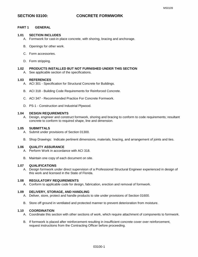
MS0109
03100-1
SECTION 03100: CONCRETE FORMWORK PART 1 GENERAL 1.01 SECTION INCLUDES A. Formwork for cast-in place concrete, with shoring, bracing and anchorage. B. Openings for other work. C. Form accessories. D. Form stripping. 1.02 PRODUCTS INSTALLED BUT NOT FURNISHED UNDER THIS SECTION A. See applicable section of the specifications. 1.03 REFERENCES A. ACI 301 - Specification for Structural Concrete for Buildings. B. ACI 318 - Building Code Requirements for Reinforced Concrete. C. ACI 347 - Recommended Practice For Concrete Formwork. D. PS-1 - Construction and Industrial Plywood. 1.04 DESIGN REQUIREMENTS A. Design, engineer and construct formwork, shoring and bracing to conform to code requirements; resultant
concrete to conform to required shape, line and dimension. 1.05 SUBMITTALS A. Submit under provisions of Section 01300. B. Shop Drawings: Indicate pertinent dimensions, materials, bracing, and arrangement of joints and ties. 1.06 QUALITY ASSURANCE A. Perform Work in accordance with ACI 318. B. Maintain one copy of each document on site. 1.07 QUALIFICATIONS A. Design formwork under direct supervision of a Professional Structural Engineer experienced in design of
this work and licensed in the State of Florida. 1.08 REGULATORY REQUIREMENTS A. Conform to applicable code for design, fabrication, erection and removal of formwork. 1.09 DELIVERY, STORAGE, AND HANDLING A. Deliver, store, protect and handle products to site under provisions of Section 01600. B. Store off ground in ventilated and protected manner to prevent deterioration from moisture. 1.10 COORDINATION A. Coordinate this section with other sections of work, which require attachment of components to formwork. B. If formwork is placed after reinforcement resulting in insufficient concrete cover over reinforcement,
request instructions from the Contracting Officer before proceeding.

MS0109
03100-2
PART 2 PRODUCTS 2.01 WOOD FORM MATERIALS A. Softwood Plywood: PS 1, C Grade. 2.02 FORMWORK ACCESSORIES A. Form Ties: Snap-off type, galvanized metal, adjustable length, 1 inch back break dimension, free of
defects that could leave holes larger than l inch in concrete surface. B. Form Release Agent: Colorless mineral oil, which will not stain concrete, or absorb moisture. C. Corners: Chamfered type, 3/4 inch x 3/4 inch size. PART 3 EXECUTION 3.01 EXAMINATION A. Verify lines, levels and centers before proceeding with formwork. Ensure that dimensions agree with
Drawings. 3.02 EARTH FORMS A. Earth forms are not permitted. 3.03 ERECTION - FORMWORK A. Erect formwork, shoring and bracing to achieve design requirements, in accordance with requirements of
ACI 301. B. Provide bracing to ensure stability of formwork. Shore or strengthen formwork subject to overstressing by
construction loads. C. Arrange and assemble formwork to permit dismantling and stripping. Do not damage concrete during
stripping. Permit removal of remaining principal shores. D. Align joints and make watertight. Keep form joints to a minimum. E. Obtain approval before framing openings in structural members, which are not indicated on Drawings. F. Provide chamfer strips on exposed external corners of concrete edge. 3.04 APPLICATION - FORM RELEASE AGENT A. Apply form release agent on formwork in accordance with manufacturer's recommendations. B. Apply prior to placement of reinforcing steel, anchoring devices, and embedded items. C. Do not apply form release agent where concrete surfaces will receive special finishes, which are effected
by agent. Soak inside surfaces of untreated forms with clean water. Keep surfaces coated prior to placement of concrete.
3.05 INSERTS, EMBEDDED PARTS, AND OPENINGS A. Provide formed openings where required for items to be embedded in or passing through concrete work. B. Locate and set in place items which will be cast directly into concrete. C. Coordinate work of other Sections in forming and placing openings, slots, reglets, recesses. chases,
sleeves, bolts. anchors, and other inserts. D. Install accessories in accordance with manufacturer's instructions, straight, level, and plumb. Ensure
items are not disturbed during concrete placement.

MS0109
03100-3
3.06 FORM CLEANING A. Clean and remove foreign matter within forms as erection proceeds. B. Clean formed cavities of debris prior to placing concrete. C. Flush with water or use compressed air to remove remaining foreign matter. Ensure that water and
debris drain to exterior through clean-out ports. D. During cold weather, remove ice from within forms. Do not use de-icing salts or water to clean out forms,
unless formwork and concrete construction proceed within heated enclosure. Use compressed air or other means to remove foreign matter.
3.07 FORMWORK TOLERANCES A. Construct formwork to maintain tolerances required by ACI 301. 3.08 FIELD QUALITY CONTROL A. Inspect erected formwork, shoring, and bracing to ensure that work is in accordance with formwork
design, and that supports, fastenings, wedges, ties, and items are secure. B. Do not reuse wood formwork more than 2 times for concrete surfaces to be exposed to view. Do not
patch formwork. 3.09 FORM REMOVAL A. Do not remove forms or bracing until concrete has gained sufficient strength to carry its own weight and
imposed loads. B. Loosen forms carefully. Do not wedge pry bars, hammers, or tools against finish concrete surfaces
scheduled for exposure to view. C. Store removed forms in manner that surfaces to be in contact with fresh concrete will not be damaged.
Discard damaged forms.
END OF SECTION

MS0109
03200-1
SECTION 03200: CONCRETE REINFORCEMENT PART 1 GENERAL 1.01 SECTION INCLUDES A. Reinforcing steel bars, wire fabric and accessories for cast in place concrete. 1.02 REFERENCES A. ACI 318 - Building Code Requirements For Reinforced Concrete. B. ANSI/ASTM A185 - Welded Steel Wire Fabric for Concrete Reinforcement. C. ASTM A615 - Deformed and Plain Billet Steel Bars for Concrete Reinforcement. D. CRSI - Concrete Reinforcing Steel Institute Manual of Practice. E. CRSI 63 - Recommended Practice For Placing Reinforcing Bars. F. CRSI 65 - Recommended Practice For Placing Bar Supports, Specifications and Nomenclature. 1.03 SUBMITTALS A. Submit under provisions of Section 01300. B. Shop Drawings: Indicate bar sizes, spacings, locations, and quantities of reinforcing steel and wire fabric,
bending and cutting schedules, and supporting and spacing devices and anchor bolt layout. C. Manufacturer's Certificate: Certify that products meet or exceed specified requirements. 1.04 QUALITY ASSURANCE A. Perform Work in accordance with CRSI 63, 65 and Manual of Practice. B. Maintain one copy of each document on site. C. Submit certified copies of mill test report of reinforcement materials analysis. 1.05 COORDINATION A. Coordinate with placement of formwork, formed openings and other Work. PART 2 PRODUCTS 2.01 REINFORCEMENT A. Reinforcing Steel: 1. ASTM A615, 60-ksi yield grade 2. Deformed billet steel bars. B. Welded Steel Wire Fabric: ASTM A185 Plain Type; in flat sheets or coiled rolls; plain finish. C. Slab on Grade Reinforcement shall be: 1. #3 rebar at 12” o/c each way. 2.02 ACCESSORY MATERIALS A. Tie Wire: Minimum 16 gauge annealed type. B. Chairs, Bolsters, Bar Supports, Spacers: Sized and shaped for strength and support of reinforcement
during concrete placement conditions including load bearing pad on bottom to prevent vapor barrier puncture. Brick or CMU may not be used for support except as permitted in paragraph 1.02 above.
2.03 FABRICATION

MS0109
03200-2
A. Fabricate concrete reinforcing in accordance with ACI 318.
PART 3 EXECUTION 3.01 PLACEMENT A. Place, support and secure reinforcement against displacement. Do not deviate from required position. B. Do not displace or damage vapor barrier. C. Accommodate placement of formed openings. D. Conform to ACI 318 for concrete cover over reinforcement. 3.02 FIELD QUALITY CONTROL A. Field inspection and testing will be performed under provisions of Section 01410. END OF SECTION

MS0109
03300-1
SECTION 03300 CAST-IN-PLACE CONCRETE PART 1 GENERAL 1.01 RELATED SPECIFICATION SECTIONS: A. Section 01000 – GENERAL REQUIREMENTS 1.02 SECTION INCLUDES A. Slabs on grade including integral footings, beams, columns, and elevated floor and roof slabs. B. Equipment pads and thrust blocks. 1.03 REFERENCES A. ACI 301 - Structural Concrete for Buildings. B. ACI 302 - Guide for Concrete Floor and Slab Construction. C. ACI 304 - Recommended Practice for Measuring, Mixing, Transporting and Placing Concrete. D. ACI 305R - Hot Weather Concreting. E. ACI 306R - Cold Weather Concreting. F. ACI 308 - Standard Practice for Curing Concrete. G. ACI 318 Building Code Requirements for Reinforced Concrete. H. ASTM C33 - Concrete Aggregates. I. ASTM C94 - Ready-Mixed Concrete. J. ASTM C150 - Portland Cement. K. ASTM C260 - Air Entraining Admixtures for Concrete. L. ASTM C494 - Chemicals Admixtures for Concrete. M. ASTM C618 - Fly Ash and Raw or Calcinated Natural Pozzolan for Use as a Mineral Admixture in Portland
Cement Concrete. N. ASTM E1745-97 Standard Specifications for Water Vapor Retarders Used in Contact with Soil or Granular
Fill Under Concrete Slabs. 1.04 SUBMITTALS A. Submit under provisions of Section 01300. B. Product Data: Provide data on joint devices, sealants, attachment accessories and admixtures. C. Concrete mix design. 1.05 PROJECT RECORD DOCUMENTS A. Accurately record actual locations of embedded utilities and components, which are concealed from view. 1.06 QUALITY ASSURANCE A. Perform Work in accordance with ACI 301. B. Maintain one copy of each document on site. C. Acquire cement and aggregate from same source for all work.

MS0109
03300-2
D. Conform to ACI 305R when concreting during hot weather. E. Conform to ACI 306R when concreting during cold weather. 1.07 FIELD SAMPLES A. Provide under provisions of Section 01410. Coordinate with Section 03100. 1.08 COORDINATION A. Coordinate the placement of joint devices with erection of concrete formwork and placement of form
accessories. PART 2 PRODUCTS 2.01 CONCRETE MATERIALS A. Cement: ASTM C150, Type I - Normal or Type III - High Early Strength Portland type. B. Fine and Coarse Aggregates: ASTM C33. Course aggregate shall be washed and shall consist of
crushed stone. Particle shape of coarse shall be generally cubicle in shape. C. Water: Clean and not detrimental to concrete. 2.02 ADMIXTURES A. Air Entrainment: ASTM C260. B. Chemical: ASTM C494, Type D - Water Reducing and Retarding or Type E - Water Reducing and
Accelerating Admixture. C. Fly Ash: ASTM C618. Type C or Type F (Loss on ignition for type F shall not exceed 6%). If an approved
pozzolanic material is used, the weight of flyash used shall not exceed 10% determined by dividing the weight of flyash by the weight of Portland cement.
D. Use of all admixtures must be approved by the Contracting Officer. The use of ‘plastisizers’ is prohibited
unless approved by the Contracting Officer. 2.03 ACCESSORIES A. Bonding Agent: Polymer resin emulsion or two component modified epoxy resin. B. Vapor Barrier: ASTM E1745-97, Class “B” reinforced, multi-ply vapor retarder (Water vapor resistance 0.3
perms, Tensile strength 30.0 lbf/in, Puncture resistance 1700 grams). Install in strict compliance with manufacturer’s written instructions including filed taping of seams and installation of pipe boots penetrating through the slab.
C. Non-shrink Grout: Premixed compound consisting of non-metallic aggregate, cement, water reducing and
plasticizing agents; capable of developing minimum compressive strength of 2,400 psi in 48 hours and 7,000 psi in 28 days.
2.04 JOINT TYPES, DEVICES AND FILLER MATERIALS A. See Section 03251 CONSTRUCTION, ISOLATION AND CONTRACTION JOINTS 2.05 CONCRETE MIX A. Mix concrete in accordance with ACI 304. Deliver concrete in accordance with ASTM C94. B. Use accelerating admixtures in cold weather only when approved by Contracting Officer. Use of
admixtures will not relax cold weather placement requirements. C. Accelerating admixtures shall not contain more than 0.1% calcium chloride. D. Use set retarding admixtures during hot weather only when approved by Contracting Officer.

MS0109
03300-3
E. Add air entraining agent to normal weight concrete mix for work exposed to exterior. PART 3 EXECUTION 3.01 EXAMINATION A. Verify site conditions. B. Verify requirements for concrete cover over reinforcement. C. Verify that anchors, seats, plates, reinforcement and other items to be cast into concrete are accurately
placed, positioned securely, and will not cause hardship in placing concrete. 3.02 PREPARATION A. Prepare previously placed concrete by cleaning with steel brush and applying bonding agent in
accordance with manufacturer's instructions. 3.03 SCHEDULE - JOINT CONTROL A. Floor Slab Perimeter and Exterior/Interior Isolation Joints: Joint filler Type A set 1/8 inch below floor slab
elevation. B. Exterior/Interior Construction Joints: Set joints to line and grade. C. Contraction Joints: Saw-cut joints to dimensions shown on the drawings. D. See 2.04.A above and specification section 03251. 3.04 PLACING CONCRETE A. Place concrete in accordance with ACI 318. B. Notify Contracting Officer minimum 24 hours prior to commencement of operations. C. Ensure reinforcement, inserts, embedded parts, formed joint fillers and joint devices are not disturbed
during concrete placement. D. Install vapor barrier under interior slabs on grade. Lap joints minimum 8 inches and seal watertight by
taping edges and ends. E. Repair vapor barrier damaged during placement of concrete reinforcing. Repair with vapor barrier
material; lap over damaged areas minimum 8 inches and seal watertight. F. Install joint fillers, primer and sealant in accordance with manufacturer's instructions. G. Install construction joint device in coordination with floor slab pattern placement sequence. Set top to
required elevations. Secure to resist movement by wet concrete. H. Install joint device anchors. Maintain correct position to allow joint cover flush with floor finish. I. Maintain records of concrete placement. Record date, location, quantity, air temperature, and test
samples taken. J. Place concrete continuously between predetermined expansion, control, and construction joints. K. Saw cut joints using 3/16-inch thick blade. Depth of cut shall not be less than one-third (1/3) the thickness
of the slab. L. Screed floors and slabs on grade level, maintaining surface flatness of maximum 1/4 inch in 10 feet. 3.05 CONCRETE TYPES AND FINISHING A. Finish concrete floor surfaces in accordance with ACI 301.

MS0109
03300-4
B. Monolithic Foundation and Slab-on-Grade: 6” thick, 3,000 psi 28 day concrete, formed to line and grade.
Steel trowel finishes surface of slab. Vertical surfaces shall be repaired/patched and finished no later than one day after form removal. Wet and rub surface with a carborundum brick or other approved abrasive, producing a satisfactory finish, smooth and uniform in color and texture. Seal all joints with an approved joint sealer.
C. Beams, Columns, Elevated Floor and Roof Slabs Exposed to View: 4,000 psi 28 day concrete.
Patch/repair surfaces after form removal, wet and rub surface with a carborundum brick or other approved abrasive after patching/repair, producing a satisfactory finish, smooth and uniform in color and texture.
D. Exposed Exterior Sidewalks, Aprons, Landings, Steps: 4” thick, 3,000 psi 28 day concrete, air entrained,
and non-slip broom finish. E. Below Grade Footings, Single-Story Structures: 3,000 psi 28 day concrete, form finish. F. Below Grade Footings, Multi-Story Structures: 4,000 psi 28 day concrete, form finish. 3.06 CURING AND PROTECTION A. Immediately after placement, protect concrete from premature drying, excessively hot or cold
temperatures, and mechanical injury. B. Maintain concrete with minimal moisture loss at relatively constant temperature for period necessary for
hydration of cement and hardening of concrete. C. Cure concrete floor surfaces to requirements of Section 03370. 3.07 FIELD QUALITY CONTROL A. Field inspection and testing will be performed in accordance with ACI 301 and under provisions of Section
01410. B. Provide free access to work and cooperate with appointed firm. C. Submit proposed mix design of each class of concrete to testing firm for review and approval prior to
commencement of work. D. Tests of cement and aggregates may be performed to ensure conformance with specified requirements. E. Three concrete test cylinders will be taken for every 40 or less cubic yards of each class of concrete
placed. Perform one compression test each at 7 days and 28 days, and one spare to be tested when directed by Contracting Officer.
F. One slump test will be taken for each set of test cylinders taken. Slump shall be within 3”-5” range except
monolithic foundation and slab-on-grade shall be within 2”-4” range. 3.08 PATCHING A. Allow Contracting Officer to inspect concrete surfaces immediately upon removal of forms. B. Excessive honeycomb or embedded debris in concrete is not acceptable. Notify Contracting Officer upon
discovery. C. Patch imperfections as directed in accordance with ACI 301. 3.09 DEFECTIVE CONCRETE A. Defective Concrete: Concrete not conforming to required lines, details, dimensions, tolerances or
specified requirements. Concrete not conforming to specified strength in 28 days will be considered defective.
B. Defective concrete will be removed and replaced. Removal will be to the nearest construction joint in all
directions. Repair of defective concrete will be permitted only upon approval from the Contracting Officer.

MS0109
03300-5
C. Do not patch, fill, touch-up, repair, or replace exposed concrete except upon express direction of
Contracting Officer for each individual area.
END OF SECTION

FTEV 08-1209 REPAIR STORM WATER DRAINAGE SYSTEM
(Airfield Waiver) HURLBURT FIELD, FLORIDA
APPENDIX A GEOTECHNICAL REPORT

Geotechnical Engineering Services Report for the Proposed
Repair Stormwater Drainage System (Airfield Waiver) Hurlburt Field AFB, Florida
PSI Project No. 0783824
Prepared for
Mr. Ken Horne, PE Kenneth Horne and Associates, Inc. 7201 N. 9th Avenue, Suite 6 Pensacola, Florida 32504
Prepared by
Professional Service Industries, Inc. 175 South A Street Pensacola, Florida 32502 Telephone (850) 434-1000 May 19, 2011


TABLE OF CONTENTS
1.0 Project Information.............................................................................................................. 1 1.1 Project Authorization ............................................................................................... 1 1.2 Project Description .................................................................................................. 1 1.3 Purpose and Scope of Services.............................................................................. 2
2.0 Site and Subsurface Conditions.......................................................................................... 3 2.1 Site Location and Description ................................................................................. 3 2.2 Subsurface Conditions ............................................................................................ 3 2.3 Groundwater Conditions ......................................................................................... 4 2.4 Laboratory Soil Testing ........................................................................................... 4 Table #1 - Corrosivity Series Test Results ..................................................................5
3.0 Evaluation and Recommendations ..................................................................................... 6 3.1 General Comments ................................................................................................. 6 3.2 Pipe Bedding and Backfilling Recommendations.................................................... 6 3.3 Foundation Recommendations ............................................................................... 7 3.4 Earth Slope/Retaining Wall Design ......................................................................... 8 Table #2 – Earth Pressure Coefficients................................................................. 8 3.5 Dewatering Considerations ..................................................................................... 9 3.6 Excavations............................................................................................................. 9
4.0 Report Limitations ............................................................................................................. 11
Figure #1 – Boring Location Plan
Figure #2 – Logs of Boring

Repair Stormwater Drainage System (Airfield Waiver) PSI Project 0783824
1
1.0 PROJECT INFORMATION
1.1 Project Authorization
Authorization to proceed on this project was issued by Mr. Ken Horne, PE via acceptance of our Geotechnical Engineering Services proposal dated March 9, 2011. A formal contract has been executed between PSI and Kenneth Horne and Associates, Inc. for these services.
1.2 Project Description
Based on the information provided, we understand that the proposed improvements are being implemented to eliminate the requirement for airfield waivers corresponding with grading and vertical obstructions associated with the existing drainage ditch. This will be accomplished by installing subsurface stormwater piping in the existing ditch and backfilling to natural grade. While initially thought to include areas north of Independence Drive, we understand that the improvements will be limited to the area south of Independence Drive.
The current improvements include replacing the existing drainage ditch with subsurface piping and installing subsurface junction boxes where the existing stormwater pond overflows into the ditch.
The proposed piping will consist of a triple corrugated metal arch pipe (8’-10” x 6’-1”) with an invert elevation at/near the existing bottom of ditch elevation. The bottom of the existing ditch is approximately 10 feet below natural grade. The pipes will bed on select sand and will be encased in soil wrapped by a geotextile with a foot or two of natural soil cover to match existing surrounding grades.
The concrete junction boxes will essentially be open-bottomed subsurface vaults. The bottoms of the vaults will be at/near the existing ditch bottom elevation, and will be lined with rip-rap and wrapped with geotextile. Based on the information provided by the project Structural Engineer, Mr. Brad Bowman, PE with Joe DeReuil Associates, LLC, the two concrete junction boxes will consist of a 12 inch thick reinforced concrete top supported by perimeter walls on a continuous footing foundation. The interior of the slabs will be supported by 14 inch square concrete columns spaced approximately 25 feet on center founded on isolated spread footings. The maximum dead loads for the continuous wall and isolated column footings are reportedly 11.5 kips/ft and 125 kips, respectively. Under the critical aircraft load of a C5-A, the maximum load on the continuous wall and isolated column footings will be 29 kips/ft and 315 kips, respectively.

Repair Stormwater Drainage System (Airfield Waiver) PSI Project 0783824
2
The foundations for the concrete junction boxes will bear approximately 4 feet below the bottom of the structures. We understand that have been designed for an allowable soil bearing pressure of 2000 psf under normal loading conditions and 4500 psf under aircraft loading conditions. The continuous wall footings are 7.5 feet wide and the isolated column footings are 8.5 feet square.
If any of the project information noted above is incorrect or has changed, please inform PSI so that we may amend the recommendations presented in this report, if necessary.
1.3 Purpose and Scope of Services
In accordance with the Scope of Services contained in our proposal dated March 9, 2011, the purpose of this exploration was to evaluate the subsurface conditions present in the subject areas and to render pipe bedding and backfilling recommendations for the proposed project. However, a change in scope which included a change in the number/depths of the borings and a request foundation recommendations for the proposed junction boxes was requested, and granted.
Our exploration consisted of four 21 foot deep Standard Penetration Test borings, three natural moisture content tests, and three wash #200 sieve tests; and a site visit, visual classification of the soil samples, and analysis by our engineering staff.
The scope of services did not include an environmental assessment for determining the presence or absence of wetlands or hazardous/toxic materials in the air, surface water(s), soil, or groundwater on or in the vicinity of the subject site. Any statements in this report or on the Logs of Boring regarding odors, stains, or unusual/suspicious conditions are strictly for the information of the client.

Repair Stormwater Drainage System (Airfield Waiver) PSI Project 0783824
3
2.0 SITE AND SUBSURFACE CONDITIONS
2.1 Site Location and Description
The segment of the open ditch included in this report is located southeast of the existing runway and begins immediately south of Independence Road on Hurlburt Field AFB, Florida. The proposed improvements to the ditch will extend approximately 1100 feet south of Independence Road.
At the time of our exploration, the open ditch was grassed with approximately 1 foot or less of running water present. A double-box culvert was present beneath Independence Road at the beginning of the study area. A retention pond was located at the southeast corner of Independence Road and the ditch. A concrete weir structure was present in the ditch approximately 135 feet south of Independence Road. Two rip-rap lined spillways connect the retention pond to the ditch approximately 80 feet and 535 feet south of Independence Road.
Based on the topographic information provided, the invert of the ditch ranged from about elevation 18 feet MSL on the north side of the project to about elevation 6 feet MSL on the south side of the project. The natural ground surface elevation ranged from about 28 feet MSL on the north side of the project to about elevation 13 feet MSL on the south side of the project.
2.2 Subsurface Conditions
Figure #1 shows the Boring Location Plan and Figure #2 shows the Logs of Boring of the four 21 foot deep Standard Penetration Test borings drilled for the project. The test borings were field located using the attached Boring Location Plan, existing field reference points on and adjacent to the site, and a handheld GPS unit (typical accuracy of 15 feet). Therefore, the boring locations should be considered approximate.
As noted in Section 1.3 above, it was initially planned to make improvements to the drainage ditch both north and south of Independence Road. However, subsequent to performing the test borings, the northern portion was eliminated from the project. This explains why boring B-1 was drilled north of Independence Road.
The borings generally encountered very loose to loose sands with varying degrees of organic stain from the ground surface to roughly 9 feet below existing grade underlain by medium dense sand with varying degrees of organic stain to the bottom of the 21 foot deep borings. Note that

Repair Stormwater Drainage System (Airfield Waiver) PSI Project 0783824
4
boring B-2 encountered a strata of very loose organic stained silty sand from roughly 7 feet to 9 feet below existing grade.
The above subsurface description is of a generalized nature, provided to highlight the major soil strata encountered. The Logs of Boring should be reviewed for specific subsurface conditions at each boring location. The stratification shown on the Logs of Boring represents the subsurface conditions at the actual boring locations only, and variations in the subsurface conditions can and may occur between boring locations and should therefore be expected. The stratification represents the approximate boundary between subsurface materials, and the transitions between strata may be gradual.
2.3 Groundwater Conditions
Groundwater was encountered roughly 9 feet below existing grade at the time of drilling, which was during a period of below normal seasonal rainfall (rainfall YTD approximately 7 inches below normal). Groundwater levels will fluctuate with rainfall and could vary several feet during typical seasonal fluctuations. Larger fluctuations are possible under severe weather conditions.
Note that the groundwater levels reported on the Logs of Boring are the levels measured at the time of drilling, and are not necessarily reflective of long term stabilized water levels encountered on the subject site. Stabilized groundwater levels can be determined by installing piezometers and measuring groundwater levels over a period of several days.
We recommend that the Contractor determine the actual groundwater levels at the time of construction to determine potential impacts groundwater can/will have on construction procedures.
2.4 Laboratory Soil Testing
Laboratory soil testing consisted of three natural moisture content tests and three wash #200 sieve tests. The results of these tests can be found on the Logs of Boring opposite the samples tested.
Two corrosion series tests (pH, chlorides, sulfides, resistivity) were performed on the major soil strata identified in the Bauer Road culvert borings RC-1 and RC-2. The results of the tests are presented in Table #1 below.

Repair Stormwater Drainage System (Airfield Waiver) PSI Project 0783824
5
Table #1 - Corrosivity Series Test Results
Boring Number
Sample Depth (feet) (1)
Sample Description pH Resistivity (ohm-cm)
Chlorides (ppm)
Sulphate (ppm)
B-3 9.5-11 Brown SAND (SP) 5.5 31,000 20 370
B-4 14.5-16 Dark brown organic stained SAND (SP) 5.7 46,000 40 250

Repair Stormwater Drainage System (Airfield Waiver) PSI Project 0783824
6
3.0 EVALUATION AND RECOMMENDATIONS
3.1 General Comments
The test borings encountered suitable subsurface conditions for the proposed improvements. Pipe bedding and backfilling recommendations for the pipeline and foundation recommendations for the proposed concrete junction structures based on the subsurface conditions encountered in the test borings (and assumed as noted above) are presented in the following sections.
3.2 Pipe Bedding and Trench Backfilling
Based on the proposed arch pipe invert elevations, the native soils beneath the majority of the pipeline will be sands with varying degrees of organic stain. These materials were medium dense in the borings, and would be suitable for supporting the pipes in there undisturbed state. Disturbed, or loose soils, should be compacted to a minimum soil density of 95% of the standard Proctor test (ASTM D698) prior to placing the geotextile and compacted bedding soils. Note that the presence of organic stain in the native soils increases their moisture sensitivity, and that yielding soils could be experienced depending on environmental factors and the effectiveness of the dewatering system. If yield materials are experienced, our office should be notified so that an evaluation can be made and recommendations rendered. Undercutting wet yielding sands and backfilling with dry, readily compactable sandy soils may be required, but will need to be evaluated at the time of construction.
Boring B-2 encountered very loose organic stained silty sand from roughly 7 feet to 9 feet below existing grade, which is very near the planned invert elevation of the pipes. These soils, if encountered at the invert, are very loose and will prove very difficult to compact as they contained fine grained moisture sensitive silt and organic stain, and because they are slow draining, will also likely remain above optimum moisture in spite of dewatering efforts. If these materials yield during compaction, and the time for additional drainage is not available, they will require either (1) need to be undercut to firmer underlying material (if present a reasonable depth below the pipe invert based on probings) and backfilled with dry, readily compactable soil to a minimum soil density of 95% of the standard Proctor test (ASTM D698), or (2) stabilized by choking angular stone into the soft soils until a stable, non-yielding matrix is achieved. Option (2) may require undercutting the very loose material about 6 inches to 1 foot below the invert elevation to account for the stone.

Repair Stormwater Drainage System (Airfield Waiver) PSI Project 0783824
7
Typically, arch pipes are encased, or “bedded”, in select sands or fine gravel as these soils more readily conform to the barrel of the pipe to provide continuous firm bedding and uniform support along the length of the pipe. Select bedding soils beneath the pipe should be hand or mechanically compacted to a minimum soil density of 100% of the Standard Proctor test (ASTM D698). Soils placed around and to not less than 24 inches above the pipe should be placed by hand and hand tamped in maximum 6 inch lifts to a minimum soil density of 100% of the standard Proctor test (ASTM D698). Backfill around the pipe should be placed simultaneously on both sides to minimize horizontal displacement of the pipe. Mechanical placement and compaction may be acceptable provided the contractor can demonstrate doing so without the formation of voids or displacing the pipe.
Backfill soils over the geotextile encased bedding soils should be placed in lifts compacted to a minimum soil density of 100% of the Standard Proctor test (ASTM D698). Backfill soils outside the horizontal limits of the geotextile encased bedding material should be compacted to a minimum soil density of 95% of the modified Proctor test (ASTM D1557).
3.3 Foundation Recommendations
Based on the structural loads and footing embedments provided, the subsurface conditions encountered in the test borings are suitable for founding the proposed concrete junction structures on shallow foundations as desired.
The soil immediately beneath and to a minimum depth of 12 inches below the footings should be compacted to a minimum soil density of 100% of the Standard Proctor test (ASTM D698).
Our calculations indicate that the proposed 7.5 foot wide continuous wall footings under dead loading conditions (11.5 kips/ft) and the 8.5 foot square column footings under dead loading conditions (125 kips) will settle approximately ¾ inch to 1 inch. Under the design aircraft load, our calculations indicate that the proposed 7.5 foot wide continuous wall footings and the 8.5 foot square column footings will settle approximately 1 ¼ inch to 1 ½ inch.
The above settlements should occur immediately upon or soon after loading, and we would expect most of the dead load settlement to occur during construction. Differential dead load settlements should be on the order of ½ of total settlements. Note that the settlement analysis for the aircraft loading condition only accounted for the dead weight of the structure and the dead weight of the aircraft. Dynamic impact loads associated with the aircraft impacting the structures was not considered in our analysis. Without significant subgrade stabilization, we

Repair Stormwater Drainage System (Airfield Waiver) PSI Project 0783824
8
would expect the wheels/landing gear (if intact) to rut the native soils and impact the concrete structures some distance below the top of the structure.
3.4 Earth Slope/Retaining Wall Design
Formal analysis of slope stability for unbraced excavations was beyond the scope of work for this project. This should be evaluated by the contractor prior to construction.
Subsurface walls restrained at the top should be designed for "at rest" earth pressure conditions. Retaining walls that are free to deflect should be designed for "active" earth pressure conditions. The "passive" earth pressure state should be used for soils supporting the retaining structure, such as toe backfill. Table #1 below presents recommended values of earth pressure coefficients based on our experience with soils in the area. Equivalent fluid densities are also provided as they are frequently used in the calculation of lateral earth pressures for the "at-rest" and "active" conditions.
TABLE #2
Earth Pressure State Earth Pressure Coefficient Equivalent Fluid Density
At-Rest 0.5 60 pcf
Active 0.3 40 pcf
Passive 3.0 360 pcf
The design values and recommendations presented above assume that the backfill behind the wall will have the following material properties:
An approximate angle of internal friction () of 30 degrees No cohesion (c=0) A total unit weight (wet) of 110 lbs/ft3
Sloping the surface of the backfill behind the walls will increase the earth pressure acting on the wall, and can be evaluated if required. The values in Table #1 do not include the effect of surcharge loads such as construction equipment, vehicle loads, or potential storage near walls. Nor do they account for hydrostatic pressures resulting from groundwater seepage entering and ponding in the backfill behind the walls, which should be included in the design as groundwater levels will rise when rainfall levels return to normal and when storm events are experienced. Any surcharge loads (and the expected groundwater pressures) should be considered in designing any structures subjected to lateral earth pressures.

Repair Stormwater Drainage System (Airfield Waiver) PSI Project 0783824
9
For analysis of sliding resistance of the base of the retaining walls, the ultimate coefficient of friction may be taken as 0.4 between concrete and soil. Backfill soils behind the walls should be compacted to a minimum soil density of 98% of the Standard Proctor test (ASTM D698).
3.5 Dewatering Considerations
Dewatering will be required to install the proposed pipeline and concrete structures as groundwater was encountered roughly 9 feet below existing grade at the time of drilling. As noted in Section 2.3 above, groundwater levels will be higher when rainfall levels return to normal. We recommend designing the dewatering system to provide dry conditions to a minimum depth of at least 2 feet below the lowest foundation elevation. The dewatering system should remain in operation until such time that removing it will not create unstable buoyant forces on the structures.
Note that to dewater the site, a Generic Permit for Stormwater Discharge from Large and Small Construction Activities (DEP Document 62-621.300(4)(a)) will be required per Florida Department of Environmental Protection (FDEP) regulations. PSI can provide Stormwater Inspection and Consulting Services during dewatering operations to ensure compliance with FDEP regulations, if desired.
3.6 Excavations
In Federal Register, Volume 54, No. 209 (October 1989), the United States Department of Labor, Occupational Safety and Health Administration (OSHA) amended its “Construction Standards for Excavations, 29 CFR, Part 1926, Subpart P”. This document was issued to better insure the safety of workmen entering trenches or excavations. It is mandated by this federal regulation that excavations, whether they be utility trenches, basement excavations or footing excavations, be constructed in accordance with the most current OSHA guidelines. It is our understanding that these regulations are being strictly enforced and if they are not closely followed, the owner and the contractor could be liable for substantial penalties.
The contractor is solely responsible for designing and constructing stable, temporary excavations and should shore, slope, or bench the sides of the excavations as required to maintain stability of both the excavation sides and bottom. The contractors “responsible person”, as defined in 29 CFR, Part 1926, should evaluate the soil exposed in the excavations as part of the contractor’s safety procedures. In no case should slope height, slope inclination, or excavation depth, including utility trench excavation depth, exceed those specified in all local, state, and federal safety regulations.

Repair Stormwater Drainage System (Airfield Waiver) PSI Project 0783824
10
We are providing this information solely as a service to our client. PSI does not assume responsibility for construction site safety or the contractor’s or other parties’ compliance with local, state, and federal safety or other regulations.
Repair Stormwater Drainage System (Airfield Waiver) PSI Project 0783824
11
4.0 REPORT LIMITATIONS
The recommendations submitted are based on the available soil information obtained by PSI and design details furnished by Mr. Lee Rentz with Kenneth Horne and Associates, Inc. and Mr. Brad Bowman, PE with Joe DeReuil Associates, LLC for the subject project. If there are any revisions to the plans for this project or if deviations from the subsurface conditions noted in this report are encountered during construction, PSI should be notified immediately to determine if changes in the foundation, or other, recommendations are required. If PSI is not retained to perform these functions, PSI can not be responsible for the impact of such conditions on the performance of the project.
The Geotechnical engineer warrants that the findings, recommendations, specifications, or professional advice contained herein have been made in accordance with generally accepted professional Geotechnical engineering practices in the local area. No other warranties are implied or expressed.
After the plans and specifications are more complete, the Geotechnical engineer should be provided the opportunity to review the final design plans and specifications to assure our engineering recommendations have been properly incorporated into the design documents. At that time, it may be necessary to submit supplementary recommendations. This report has been prepared for the exclusive use of Kenneth Horne and Associates, Inc. for the specific application to the subject project.

Figure #1 Sheet 1 of 2
5/17/11
Hurlburt Field Stormwater RepairHurlburt Field AFB, Florida
PSI Project # 0783824
N
Boring Location Plan
B-2
80 ft 160 ft0 ft
B-1
Ru
nw
ay
Existing Stormwater Ditch
B-3
B-4
Existing Stormwater Retention Pond
Loop RoadProposed Concrete Structure
Proposed EndwallStructure
Existing Weir Structure
Proposed Concrete Structure

SP
SP
SP
SP
2-3-4N=7
2-2-2N=4
7-12-13N=25
6-8-8N=16
4-12-14N=26
1
2
3
4
5
6
7
Gray SAND
Brown SAND
Light brown very loose to loose SAND
Brown medium dense SAND
PL
Ele
vatio
n (f
eet)
LL
4.0
25
Rec
over
y (in
ches
)Station: N/AOffset: N/A
The stratification lines represent approximate boundaries. The transition may be gradual.
Dep
th, (
feet
)
Sample Types:
STRENGTH, tsf
9 feet
9 feet
N/A
0783824Hurlburt Field - Drainage Stormwater RepairHurlburt Field AFBFlorida
AdditionalRemarks
US
CS
Cla
ssifi
catio
n
Boring Location:
0
Qp
Sheet 1 of 1
0
5
10
15
20
Professional Service Industries, Inc.175 S. "A" StreetPensacola, FL 32502Telephone: (850) 434-1000Fax: (850) 434-7200
Sam
ple
Typ
e
2.0
While Drilling
Upon Completion
Delay
Drilling Method:Sampling Method:Hammer Type:
0
WATER LEVELS
Moi
stur
e, %
MoistureMATERIAL DESCRIPTION
STANDARD PENETRATIONTEST DATA
N in blows/ft
PSI Job No.:Project:Location:
Latitude: 30.4173°Longitude: -86.68523°Drill Rig: SIMCORemarks:
Shelby Tube
Hand Auger
Calif. Sampler
Texas Cone
SP
T B
low
s pe
r 6-
inch
(S
S)
Auger2-in SSSafety
Qu
Auger Cutting
Split-Spoon
Rock Core
Per Boring Location Plan
Sam
ple
No.
Gra
phic
Log
LOG OF BORING B-1
50
Completion Depth:Date Boring Started:Date Boring Completed:Logged By:Drilling Contractor:
21.0 ft
4/27/11J. R. PeelSouthern Testing

29
SP
SM
SP
2-2-1N=3
2-1-2N=3
2-1-2N=3
1-1-1N=2
8-12-15N=27
6-12-13N=25
4-10-13N=23
-200=17%
1
2
3
4
5
6
7
Dark brown very loose organic stained SAND
Dark brown very loose organic stained siltySAND
Dark brown medium dense organic stainedSAND
PL
Ele
vatio
n (f
eet)
20
15
10
5
LL
4.0
25
Rec
over
y (in
ches
)Station: N/AOffset: N/A
The stratification lines represent approximate boundaries. The transition may be gradual.
Dep
th, (
feet
)
Sample Types:
STRENGTH, tsf
9 feet
9 feet
N/A
0783824Hurlburt Field - Drainage Stormwater RepairHurlburt Field AFBFlorida
AdditionalRemarks
US
CS
Cla
ssifi
catio
n
Boring Location:
0
Qp
Sheet 1 of 1
0
5
10
15
20
Professional Service Industries, Inc.175 S. "A" StreetPensacola, FL 32502Telephone: (850) 434-1000Fax: (850) 434-7200
Sam
ple
Typ
e
2.0
While Drilling
Upon Completion
Delay
Drilling Method:Sampling Method:Hammer Type:
0
WATER LEVELS
Moi
stur
e, %
MoistureMATERIAL DESCRIPTION
STANDARD PENETRATIONTEST DATA
N in blows/ft
PSI Job No.:Project:Location:
Latitude: 30.41549°Longitude: -86.68529°Drill Rig: SIMCORemarks:
Shelby Tube
Hand Auger
Calif. Sampler
Texas Cone
SP
T B
low
s pe
r 6-
inch
(S
S)
Auger2-in SSSafety
Qu
Auger Cutting
Split-Spoon
Rock Core
Per Boring Location Plan
Sam
ple
No.
Gra
phic
Log
LOG OF BORING B-2
50
Completion Depth:Date Boring Started:Date Boring Completed:Logged By:Drilling Contractor:
21.0 ft
4/27/11J. R. PeelSouthern Testing
Surface Elev.: 24 ft

7
SP
SP
SP
2-3-3N=6
2-3-4N=7
2-2-3N=5
5-4-4N=8
3-6-7N=13
3-6-8N=14
2-6-9N=15
-200=1%
1
2
3
4
5
6
7
Gray loose SAND
Dark brown/brown loose organic stained SAND
Brown medium dense SAND
PL
Ele
vatio
n (f
eet)
20
15
10
5
LL
4.0
25
Rec
over
y (in
ches
)Station: N/AOffset: N/A
The stratification lines represent approximate boundaries. The transition may be gradual.
Dep
th, (
feet
)
Sample Types:
STRENGTH, tsf
9 feet
9 feet
N/A
0783824Hurlburt Field - Drainage Stormwater RepairHurlburt Field AFBFlorida
AdditionalRemarks
US
CS
Cla
ssifi
catio
n
Boring Location:
0
Qp
Sheet 1 of 1
0
5
10
15
20
Professional Service Industries, Inc.175 S. "A" StreetPensacola, FL 32502Telephone: (850) 434-1000Fax: (850) 434-7200
Sam
ple
Typ
e
2.0
While Drilling
Upon Completion
Delay
Drilling Method:Sampling Method:Hammer Type:
0
WATER LEVELS
Moi
stur
e, %
MoistureMATERIAL DESCRIPTION
STANDARD PENETRATIONTEST DATA
N in blows/ft
PSI Job No.:Project:Location:
Latitude: 30.41453°Longitude: -86.68522°Drill Rig: SIMCORemarks:
Shelby Tube
Hand Auger
Calif. Sampler
Texas Cone
SP
T B
low
s pe
r 6-
inch
(S
S)
Auger2-in SSSafety
Qu
Auger Cutting
Split-Spoon
Rock Core
Per Boring Location Plan
Sam
ple
No.
Gra
phic
Log
LOG OF BORING B-3
50
Completion Depth:Date Boring Started:Date Boring Completed:Logged By:Drilling Contractor:
21.0 ft
4/27/11J. R. PeelSouthern Testing
Surface Elev.: 22 ft

4
SP
SP
2-2-2N=4
2-2-2N=4
2-1-2N=3
5-3-3N=6
6-9-9N=18
5-9-11N=20
6-9-11N=20
-200=1%
1
2
3
4
5
6
7
Brown very loose to loose SAND
Dark brown loose to medium dense organicstained SAND
PL
Ele
vatio
n (f
eet)
15
10
5
0
-5
LL
4.0
25
Rec
over
y (in
ches
)Station: N/AOffset: N/A
The stratification lines represent approximate boundaries. The transition may be gradual.
Dep
th, (
feet
)
Sample Types:
STRENGTH, tsf
9 feet
9 feet
N/A
0783824Hurlburt Field - Drainage Stormwater RepairHurlburt Field AFBFlorida
AdditionalRemarks
US
CS
Cla
ssifi
catio
n
Boring Location:
0
Qp
Sheet 1 of 1
0
5
10
15
20
Professional Service Industries, Inc.175 S. "A" StreetPensacola, FL 32502Telephone: (850) 434-1000Fax: (850) 434-7200
Sam
ple
Typ
e
2.0
While Drilling
Upon Completion
Delay
Drilling Method:Sampling Method:Hammer Type:
0
WATER LEVELS
Moi
stur
e, %
MoistureMATERIAL DESCRIPTION
STANDARD PENETRATIONTEST DATA
N in blows/ft
PSI Job No.:Project:Location:
Latitude: 30.41343°Longitude: -86.68508°Drill Rig: SIMCORemarks:
Shelby Tube
Hand Auger
Calif. Sampler
Texas Cone
SP
T B
low
s pe
r 6-
inch
(S
S)
Auger2-in SSSafety
Qu
Auger Cutting
Split-Spoon
Rock Core
Per Boring Location Plan
Sam
ple
No.
Gra
phic
Log
LOG OF BORING B-4
50
Completion Depth:Date Boring Started:Date Boring Completed:Logged By:Drilling Contractor:
21.0 ft
4/27/11J. R. PeelSouthern Testing
Surface Elev.: 16 ft

APPENDIX “B”
FDEP GENERIC PERMIT FOR THE DISCHARGE OF PRODUCED GROUNDWATER FROM ANY NON-
CONTAMINATED SITE ACTIVITY

STATE OF FLORIDA
DEPARTMENT OF ENVIRONMENTAL PROTECTION
GENERIC PERMIT
FOR THE
DISCHARGE OF PRODUCED GROUND WATER
FROM ANY NON-CONTAMINATED SITE ACTIVITY
Document number 62-621.300(2) Effective Date: February 14, 2000
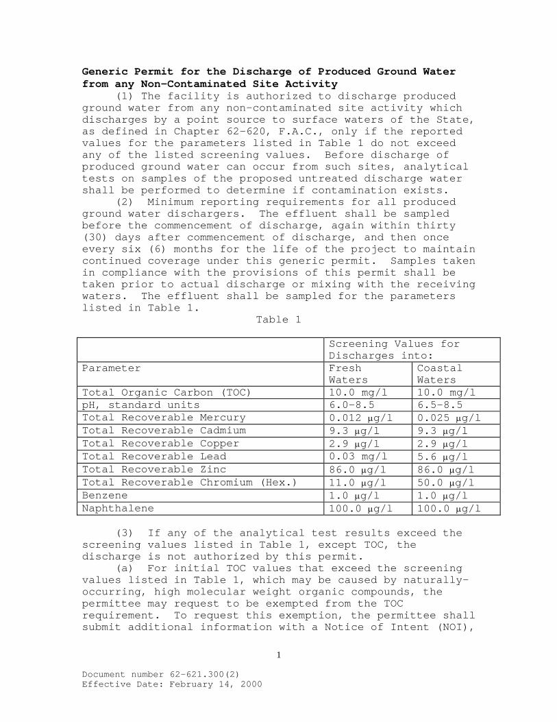
1
Document number 62-621.300(2) Effective Date: February 14, 2000
Generic Permit for the Discharge of Produced Ground Water from any Non-Contaminated Site Activity (1) The facility is authorized to discharge produced ground water from any non-contaminated site activity which discharges by a point source to surface waters of the State, as defined in Chapter 62-620, F.A.C., only if the reported values for the parameters listed in Table 1 do not exceed any of the listed screening values. Before discharge of produced ground water can occur from such sites, analytical tests on samples of the proposed untreated discharge water shall be performed to determine if contamination exists. (2) Minimum reporting requirements for all produced ground water dischargers. The effluent shall be sampled before the commencement of discharge, again within thirty (30) days after commencement of discharge, and then once every six (6) months for the life of the project to maintain continued coverage under this generic permit. Samples taken in compliance with the provisions of this permit shall be taken prior to actual discharge or mixing with the receiving waters. The effluent shall be sampled for the parameters listed in Table 1.
Table 1
Screening Values for Discharges into:
Parameter Fresh Waters
Coastal Waters
Total Organic Carbon (TOC) 10.0 mg/l 10.0 mg/l pH, standard units 6.0-8.5 6.5-8.5 Total Recoverable Mercury 0.012 μg/l 0.025 μg/l Total Recoverable Cadmium 9.3 μg/l 9.3 μg/l Total Recoverable Copper 2.9 μg/l 2.9 μg/l Total Recoverable Lead 0.03 mg/l 5.6 μg/l Total Recoverable Zinc 86.0 μg/l 86.0 μg/l Total Recoverable Chromium (Hex.) 11.0 μg/l 50.0 μg/l Benzene 1.0 μg/l 1.0 μg/l Naphthalene 100.0 μg/l 100.0 μg/l (3) If any of the analytical test results exceed the screening values listed in Table 1, except TOC, the discharge is not authorized by this permit. (a) For initial TOC values that exceed the screening values listed in Table 1, which may be caused by naturally-occurring, high molecular weight organic compounds, the permittee may request to be exempted from the TOC requirement. To request this exemption, the permittee shall submit additional information with a Notice of Intent (NOI),

2
Document number 62-621.300(2) Effective Date: February 14, 2000
described below, which describes the method used to determine that these compounds are naturally occurring. The Department shall grant the exemption if the permittee affirmatively demonstrates that the TOC values are caused by naturally-occurring, high molecular weight organic compounds. (b) The NOI shall be submitted to the appropriate Department district office thirty (30) days prior to discharge, and contain the following information: 1. the name and address of the person that the permit coverage will be issued to; 2. the name and address of the facility, including county location; 3. any applicable individual wastewater permit number(s); 4. a map showing the facility and discharge location (including latitude and longitude); 5. the name of the receiving water; and 6. the additional information required by paragraph (3)(a) of this permit. (c) Discharge shall not commence until notification of coverage is received from the Department. (4) For fresh waters and coastal waters, the pH of the effluent shall not be lowered to less than 6.0 units for fresh waters, or less than 6.5 units for coastal waters, or raised above 8.5 units, unless the permittee submits natural background data confirming a natural background pH outside of this range. If natural background of the receiving water is determined to be less than 6.0 units for fresh waters, or less than 6.5 units in coastal waters, the pH shall not vary below natural background or vary more than one (1) unit above natural background for fresh and coastal waters. If natural background of the receiving water is determined to be higher than 8.5 units, the pH shall not vary above natural background or vary more than one (1) unit below natural background of fresh and coastal waters. The permittee shall include the natural background pH of the receiving waters with the results of the analyses required under paragraph (2) of this permit. For purposes of this section only, fresh waters are those having a chloride concentration of less than 1500 mg/l, and coastal waters are those having a chloride concentration equal to or greater than 1500 mg/l. (5) In accordance with Rule 62-302.500(1)(a-c), F.A.C., the discharge shall at all times be free from floating solids, visible foam, turbidity, or visible oil in such amounts as to form nuisances on surface waters.

3
Document number 62-621.300(2) Effective Date: February 14, 2000
(6) If contamination exists, as indicated by the results of the analytical tests required by paragraph (2), the discharge cannot be covered by this generic permit. The facility shall apply for an individual wastewater permit at least ninety (90) days prior to the date discharge to surface waters of the State is expected, or, if applicable, the facility may seek coverage under any other applicable Department generic permit. No discharge is permissible without an effective permit. (7) If the analytical tests required by paragraph (2) reveal that no contamination exists from any source, the facility can begin discharge immediately and is covered by this permit without having to submit an NOI request for coverage to the Department. A short summary of the proposed activity and copy of the analytical tests shall be sent to the applicable Department district office within one (1) week after discharge begins. These analytical tests shall be kept on site during discharge and made available to the Department if requested. Additionally, no Discharge Monitoring Report forms are required to be submitted to the Department. (8) All of the general conditions listed in Rule 62-621.250, F.A.C., are applicable to this generic permit. (9) There are no annual fees associated with the use of this generic permit.