Specification - Relay HD the manual control adds the below additional benefits: ... ETP Copper 99%...
10
Confidential and Proprietary – The information contained within this document is the property of Littelfuse, Inc. It should be considered confidential and proprietary, and shall not be read, copied, or distributed without the express written consent of Littelfuse, Inc. Terra Power Systems is now a Littelfuse Company P P R R O O D D U U C C T T S S P P E E C C I I F F I I C C A A T T I I O O N N HD Series Bi-Stable Relay Rev. 1.0 February 2, 2011
Transcript of Specification - Relay HD the manual control adds the below additional benefits: ... ETP Copper 99%...

Confidential and Proprietary – The information contained within this document is the property of
Littelfuse, Inc. It should be considered confidential and proprietary, and shall not be read, copied, or
distributed without the express written consent of Littelfuse, Inc.
Terra Power Systems is now a Littelfuse Company
PPRROODDUUCCTT SSPPEECCIIFFIICCAATTIIOONN
HHDD SSeerriieess BBii--SSttaabbllee RReellaayy
RReevv.. 11..00
February 2, 2011

Page 2 of 10 Littelfuse, Inc.
Confidential and Proprietary – The information contained within this document is the property of
Littelfuse, Inc. It should be considered confidential and proprietary, and shall not be read, copied, or
distributed without the express written consent of Littelfuse, Inc.
Revision History
Revision Date Description of Change
1.0 2/2/2011 Initial Release
A – Product Requirements, Performance Requirements, & Quality Objectives
Product Variations
Part Number Description
880086 Relay HD 12V 300A with Deutsch DTM
880088 Relay HD 24V 300A with Deutsch DTM
Module Description
The HD Series Bi-Stable Relay (HD Relay) is designed to deliver and remotely switch vehicle loads. The
HD Relay supports remote power switching applications that demand high performance; including high
continuous current passage, large inverter loads, and high ambient temperature situations. The HD
Relay delivers high performance in a compact size, making it a great choice for heavy-duty vehicles,
construction and agriculture equipment, military vehicles, and heavy-duty lifting equipment.
The HD Relay is designed for harsh weather, high shock and vibration environments; typical of those
found in heavy-truck, marine, and emergency vehicle applications. The HD Relay without manual
override is ingress rated to IP67 and all HD Relay products are rated for IP6K9K ingress protection to
support direct high temperature high pressure wash down.
The HD Relay provides significant cost and weight benefits by eliminating the need to route heavy
copper cables to more conveniently located mechanical only disconnects. Cables can instead be routed
directly to loads with the HD Relay positioned close to the battery or in-line with the desired cable
routing. Remote control of the HD Relay can then be located in any convenient location on the vehicle
Page 3 of 10 Littelfuse, Inc.
Confidential and Proprietary – The information contained within this document is the property of
Littelfuse, Inc. It should be considered confidential and proprietary, and shall not be read, copied, or
distributed without the express written consent of Littelfuse, Inc.
with a fine-wire harness linking the HD Relay to the control switch. The HD Relay family of products
provide a host of additional features that add significant value for many typical applications, including:
• Remote LED indication of state of disconnect and warning of imminent disconnect due to
low battery voltage
• Local and remote indication of state of relay (Local indication on Manual Override models
only)
Application Schematic
The HD Relay provides high-current carrying and switching under load. The Remote Battery
Switch/Solenoid Switch is installed close to the battery banks. A single pole double throw (SPDT) Control
Switch Panel, or two momentary push button switches, operate the HD Series Bi-Stable Relay. Control
Switches are often installed in a convenient accessible location.
Module Operation
Remote Operation – Use a momentary (SPDT) (ON)-OFF-(ON) Control Switch (sold separately), as shown
in the application schematic, the HD Relay can be turned ON and OFF by momentarily actuating the
control switch in the desired direction.
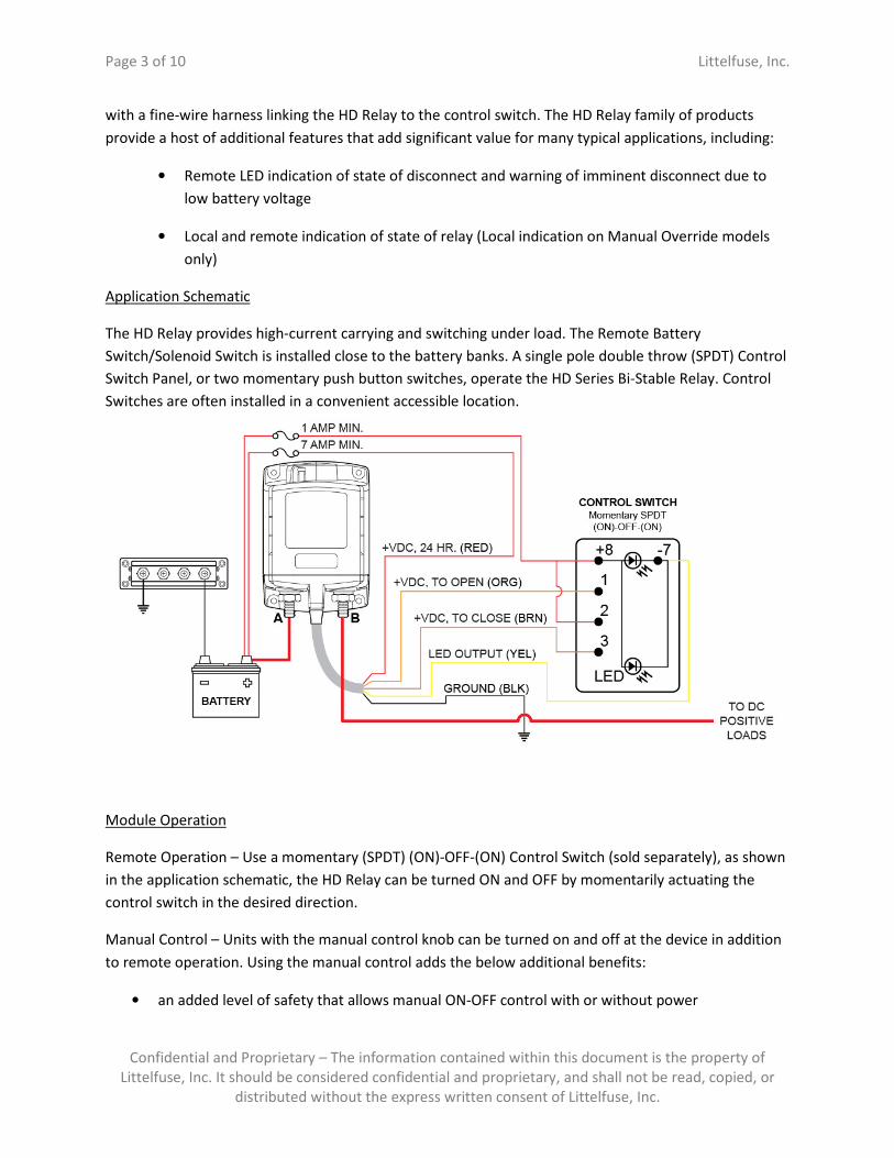
Manual Control – Units with the manual control knob can be turned on and off at the device in addition
to remote operation. Using the manual control adds the below additional benefits:
• an added level of safety that allows manual ON-OFF control with or without power
Page 4 of 10 Littelfuse, Inc.
Confidential and Proprietary – The information contained within this document is the property of
Littelfuse, Inc. It should be considered confidential and proprietary, and shall not be read, copied, or
distributed without the express written consent of Littelfuse, Inc.
• LOCK OFF for servicing the electrical system
Manual Operation of units with the Manual Control option:
A remote LED (sold separately) indicates a closed connection between battery bank and load, or
between two battery banks when used as battery cross-connect.
Unit Connections
The HD Relays have two (2) high-amperage 3/8” terminals for connection to a primary power source and
the load connection. The control wire connections are made through a multi-wire control cable
connected to either a 6 position Sealed Deutsch DTM connector, stripped and tinned wires, or a
customer specified connector solution.
The device should be assembled to a flat surface with the four (4) clearance holes counter-bored to
receive pan head #10 or M5 screws.
Local & Remote Indicators
This device has a single remote LED indicator pull-down which is solid ON when the device is closed and
connecting the input and output terminals (A and B), and is OFF when the device is open and isolating
the input and output terminals. The LED indicator will double flash if there is a failure of the device to
open or close.
Product Identification and Marking
All products come with a combination part number / date code label to provide a unique identifier for
testing and warranty purposes. Removal of this label will void the product warranty.
Page 5 of 10 Littelfuse, Inc.
Confidential and Proprietary – The information contained within this document is the property of
Littelfuse, Inc. It should be considered confidential and proprietary, and shall not be read, copied, or
distributed without the express written consent of Littelfuse, Inc.
The label area on the front of the device is used for identification of the terminal designations and other
critical or custom component information. Contact Terra Power Systems for more details on arranging
custom product variations.
Warranty
All HD Relay devices are warranted free from manufacturing defects or product failure within prescribed
environmental limitations for a period of one (1) year.
Traceability
Date code labelling of products is performed to improve lot traceability.
Packaging
Aftermarket products are provided in single-pack packaging suitable for commercial distribution. OEM
bulk pack large orders shall be packaged in a corrugated cardboard box with corrugated cardboard
dividers, designed for effective pallet loading and stacking and to minimize environmental impact.
Smaller OEM standard pack quantities are also available. Contact Terra Power Systems for additional
packaging details and options.
Life, Reliability, Durability
All HD Relay variations are designed to withstand operation for 10 years and 1,000,000 miles in a heavy-
duty truck environment. The product is also designed to withstand a minimum of 10 years of regular use
within a harsh and corrosive marine environment.
Customized Options
Contact Terra Power Systems for custom variations with unique delay features or auxiliary contact logic.
Variations to control switch logic and inclusion of voltage sensing, automatic relay operation, and CAN
based communication protocols may be added to customized variations of this product.
Maintainability
The product is designed to accept regular high pressure, high temperature pressure washing (IP 9K)
without collecting water inside or electrically shorting. No maintenance of the product is required during
its service life. Regular inspection of control connector integrity and terminal nut torque is
recommended to ensure optimal system up-time.
Electrical Description
The HD Relay electrically consists of two input/output terminals each with an embedded silver alloy
contact. One heavy-duty primary internal relay is utilized to provide low contact resistance while
connecting and disconnecting a large moveable copper bus bar with embedded silver alloy contacts.

Page 6 of 10 Littelfuse, Inc.
Confidential and Proprietary – The information contained within this document is the property of
Littelfuse, Inc. It should be considered confidential and proprietary, and shall not be read, copied, or
distributed without the express written consent of Littelfuse, Inc.
Mechanical Description
See outline drawings at end of document.
Electrical Power Specifications
Parameter Value
Maximum Continuous Current
(4/0 Input / Output Cables) 300 A
Maximum Intermittent Current, 30 Second Duration
(4/0 Input / Output Cables) 1,000 A
Maximum Inrush Current, 1 Second Duration
(4/0 Input / Output Cables) 2,000 A
Miscellaneous Electrical Specifications
Parameter Value
Live Switching Current
(12Vdc, 3,000 operations max)
500 A Make / 250 A
Break
Live Switching Current
(12Vdc, 10,000 operations max)
250 A Make / 150 A
Break
Live Switching Current
(12Vdc, 3,000 operations max)
500 A Make / 250 A
Break
Dielectric Breakdown Withstand 1100 VDC, 2 min
External Remote LED Max Fwd V-drop TBD
24Hr Protected Tachograph Output Max Current 1 A
Emergency Break Current, 12V DC nominal 1,500 A / 10 times
Emergency Break Current, 24V DC nominal 750 A / 10 times
Power Consumption – Steady-State (On or Off) 15 mA
Power Consumption – Changing State to On or Off 7 A Max
I/O Connections
Connection Gauge Function Max Current
“A” Max 4/0 AWG High Current I/O - A 300 A (4/0 Cable)
“B” Max 4/0 AWG High Current I/O - B 300 A (4/0 Cable)
Control Connections Wire
Color Wire Gauge Max Current
De
uts
ch
DT
M
Co
nn
ect
or
Pin
#
Ground, Reference for Source Battery Black 22 – 16 AWG 7 A (momentary) 1
+VDC, 24 Hour Red 22 – 16 AWG 50 mA 2
Page 7 of 10 Littelfuse, Inc.
Confidential and Proprietary – The information contained within this document is the property of
Littelfuse, Inc. It should be considered confidential and proprietary, and shall not be read, copied, or
distributed without the express written consent of Littelfuse, Inc.
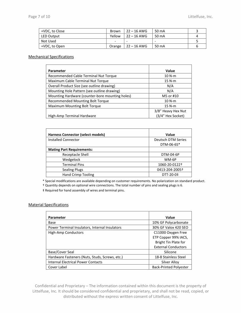
+VDC, to Close Brown 22 – 16 AWG 50 mA 3
LED Output Yellow 22 – 16 AWG 50 mA 4
Not Used - - - 5
+VDC, to Open Orange 22 – 16 AWG 50 mA 6
Mechanical Specifications
* Special modifications are available depending on customer requirements. No polarization on standard product.
† Quantity depends on optional wire connections. The total number of pins and sealing plugs is 6.
‡ Required for hand assembly of wires and terminal pins.
Material Specifications
Parameter Value
Base 10% GF Polycarbonate
Power Terminal Insulators, Internal Insulators 30% GF Valox 420 SEO
High-Amp Conductors C11000 Oxygen Free
ETP Copper 99% IACS,
Bright Tin Plate for
External Conductors
Base/Cover Seal Silicone
Hardware Fasteners (Nuts, Studs, Screws, etc.) 18-8 Stainless Steel
Internal Electrical Power Contacts Silver Alloy
Cover Label Back-Printed Polyester
Parameter Value
Recommended Cable Terminal Nut Torque 10 N-m
Maximum Cable Terminal Nut Torque 15 N-m
Overall Product Size (see outline drawing) N/A
Mounting Hole Pattern (see outline drawing) N/A
Mounting Hardware (counter-bore mounting holes) M5 or #10
Recommended Mounting Bolt Torque 10 N-m
Maximum Mounting Bolt Torque 15 N-m
High-Amp Terminal Hardware
3/8” Heavy Hex Nut
(3/4” Hex Socket)
Harness Connector (select models) Value
Installed Connector Deutsch DTM Series
DTM-06-6S*
Mating Part Requirements:
Receptacle Shell DTM-04-6P
Wedgelock WM-6P
Terminal Pins 1060-20-0122†
Sealing Plugs 0413-204-2005†
Hand Crimp Tooling DTT-20-0‡

Page 8 of 10 Littelfuse, Inc.
Confidential and Proprietary – The information contained within this document is the property of
Littelfuse, Inc. It should be considered confidential and proprietary, and shall not be read, copied, or
distributed without the express written consent of Littelfuse, Inc.
or Polycarbonate
Environmental Specifications
Parameter (Reference Standards) Value
Temperature, Operational (SAE J1455, Sec 4.1.3.1) -50 C to 85 C
Temperature, Non-Operational (SAE J1455, Sec 4.1.3.1) -55 C to 105 C
Temperature Shock (SAE J1455, Sec 4.1.3.2) -40 C to 85 C
Humidity Cycle (SAE J1455, Sec 4.2.3, Fig 4a) 0 – 95% RH
Dust Bombardment (SAE J1455, Sec 4.7.3) Pass
Salt Spray (SAE J1455, Sec 4.3) 1,000 Hours
Operational Shock - Operational (MIL-STD-202-F, Method
213B, Condition J) 10 G*
Handling Shock – (SAE J1455, Sec 4.10.3.1) See Spec
Transit Drop (SAE J1455, Sec 4.10.3.2.2) See Spec
Operational Vibration, 3 Axis, Power Density Level of 0.2535
G^2/Hz @ 5-100 Hz, 3db per octave roll-off to 500 Hz 8 G†
Steam Cleaning & Pressure Wash (SAE J1455, Sec 4.5) Pass
Ingress Protection (DIN 40050-9) IP 67 (non-knob
versions only) & IP6K9K
(all versions)
Chemicals and Oils Withstand, Immersion and Splash (SAE
J1455, Sec 4.4, all listed elements) Pass
UV Exposure (ASTM G155) 50 days
* Minimum Operational Shock Values for shock in line with solenoid action and parallel to terminal stud. Operational
Shock value in orientations perpendicular to terminal studs and solenoid action is 50 G.
† Minimum Operational Vibration Values for shock in line with solenoid action and parallel to terminal stud.
Operational Vibration value in orientations perpendicular to terminal studs and solenoid action is 20 G.
Electrical Environmental Specifications
Parameter Standard(s) Met
Steady State - Normal Operation SAE J1455, Sec 4.11.1
Steady State - Reverse Polarity -24V SAE J1455, Sec 4.11.1
Steady State - Jump Start +24V SAE J1455, Sec 4.11.1
Steady State - Cold Cranking 0-6V SAE J1455, Sec 4.11.1
Steady State - Series Charging +48V SAE J1455, Sec 4.11.1
Page 9 of 10 Littelfuse, Inc.
Confidential and Proprietary – The information contained within this document is the property of
Littelfuse, Inc. It should be considered confidential and proprietary, and shall not be read, copied, or
distributed without the express written consent of Littelfuse, Inc.
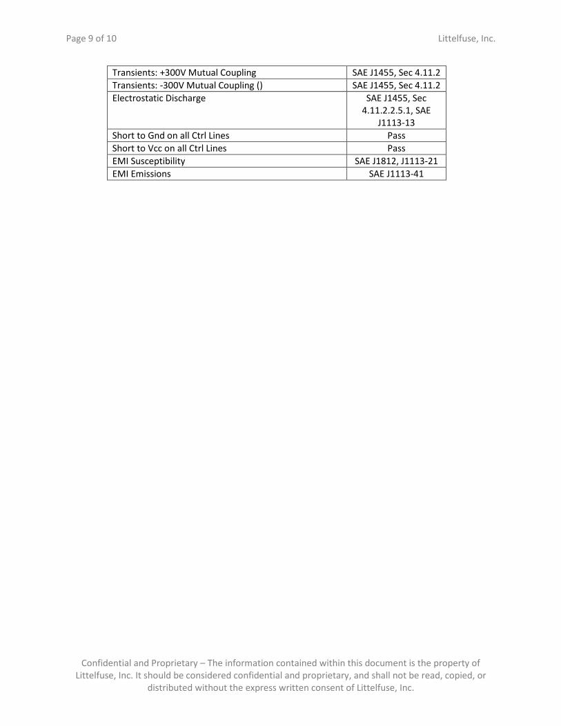
Transients: +300V Mutual Coupling SAE J1455, Sec 4.11.2
Transients: -300V Mutual Coupling () SAE J1455, Sec 4.11.2
Electrostatic Discharge SAE J1455, Sec
4.11.2.2.5.1, SAE
J1113-13
Short to Gnd on all Ctrl Lines Pass
Short to Vcc on all Ctrl Lines Pass
EMI Susceptibility SAE J1812, J1113-21
EMI Emissions SAE J1113-41

Page 10 of 10 Littelfuse, Inc.
Confidential and Proprietary – The information contained within this document is the property of
Littelfuse, Inc. It should be considered confidential and proprietary, and shall not be read, copied, or
distributed without the express written consent of Littelfuse, Inc.
Module Outline Drawing