SPECIFICATION OF ELECTRICAL PANEL - ITI...
28
ITI DATA CENTER @ BENGALURU ANNEXURE-3 Page 1 of 24 DGM(GSM,NGN&IT) RCEE(AS)&DC SPECIFICATION OF ELECTRICAL PANEL ELIGIBILITY CRITERIA The Bidder must possess the requisite experience, strength and capabilities in providing the services necessary to meet the requirements as described. Keeping in view the complexity & volume of the work involved, the following criteria are prescribed as pre- qualification criteria for Bidder interested in undertaking the project. The Bidder must also possess the technical know-how and the financial where withal that would be required to successfully Completion of the Data Centre within a time. The bids must be complete in all respect and should cover the entire scope of work as stipulated in the tender document. The invitation to bid is open to all Bidders who qualify the eligibility criteria as given below: Sr No Criteria List Documents required Compliance by vendor 1 The Bidder (prime) should be a Company registered Under the Companies Act, 1956 since last 5 years ending 31st March 2017 Certificate of incorporation and Self Certification of being in the business for the last 5 years should be attached. 2 Company should have AN ISO 9001: 2008 CERTIFIED COMPANY Certification to be submitted 3 No joint-venture (JV) is allowed for this project Proof to be submitted with Self declaration. 4 The bidder should have successfully completed as a at least 3 Data Centre work PO Copies / Complétion Certification to be attached with self-attestation NOTE: 1. Each and every page of this RFP should be stamped & signed by the bidder as a token of acceptance of this RFP conditions. Deviation if any, shall be clearly mentioned in a separate sheet of paper. However, accepting the bid with deviation is the sole discretion of Tenderer. 2. Any query in this Bid should reach the Tenderer within 8 working days from the release of Tender Enquiry. Thereafter No query will be entertained.
Transcript of SPECIFICATION OF ELECTRICAL PANEL - ITI...

ITI DATA CENTER @ BENGALURU ANNEXURE-3
Page 1 of 24
DGM(GSM,NGN&IT) RCEE(AS)&DC
SPECIFICATION OF ELECTRICAL PANEL
ELIGIBILITY CRITERIA
The Bidder must possess the requisite experience, strength and capabilities in providing the services
necessary to meet the requirements as described. Keeping in view the complexity & volume of the work
involved, the following criteria are prescribed as pre- qualification criteria for Bidder interested in
undertaking the project. The Bidder must also possess the technical know-how and the financial where
withal that would be required to successfully Completion of the Data Centre within a time. The bids must
be complete in all respect and should cover the entire scope of work as stipulated in the tender
document. The invitation to bid is open to all Bidders who qualify the eligibility criteria as given below:
Sr No
Criteria List Documents required Compliance by
vendor
1
The Bidder (prime) should be a Company registered Under the Companies Act, 1956 since last 5 years ending 31st March 2017
Certificate of incorporation and Self Certification of being in the business for the last 5 years should be attached.
2 Company should have AN ISO 9001:
2008 CERTIFIED COMPANY Certification to be submitted
3 No joint-venture (JV) is allowed for
this project Proof to be submitted with Self
declaration.
4 The bidder should have successfully
completed as a at least 3 Data Centre work
PO Copies / Complétion Certification to be attached with self-attestation
NOTE: 1. Each and every page of this RFP should be stamped & signed by the bidder as a token of acceptance
of this RFP conditions. Deviation if any, shall be clearly mentioned in a separate sheet of paper. However, accepting the bid with deviation is the sole discretion of Tenderer. 2. Any query in this Bid should reach the Tenderer within 8 working days from the release of Tender
Enquiry. Thereafter No query will be entertained.

ITI DATA CENTER @ BENGALURU ANNEXURE-3
Page 2 of 24
DGM(GSM,NGN&IT) RCEE(AS)&DC
GENERAL SPECIFICATIONS
i. SCOPE:
In general, the prime vendor shall design , supply, deliver, test and commission assist to Low side electrical
contractor for installation.
Testing of panels at factory for function test , Insulation resistance test , HV test as per standard practice .
ii. Prime Vendor:
He shall be CPRI approved having valid license, employing supervisors and skilled workers having a valid
permits as per the Regulation of Indian Electricity Rules and Local Electrical Inspector’s requirements and
the same shall be got renewed from time to time.
iii. INFORMATION TO BIDDERS:
a. The design and quality of goods supplied and the workmanship shall be in accordance with the
best engineering practice to ensure satisfactory performance of the system throughout the service life.
b. The goods and accessories offered shall be complete in all respects. Any material, and/ or
component not specifically stated in this specification which is necessary for trouble free and successful
operation shall be deemed to be included unless specifically excluded. All such components, accessories,
etc., shall be supplied at no extra cost.
c. The goods supplied shall be such that components, accessories of the same type shall be
interchangeable. Likewise similar or corresponding parts, components/ accessories shall also be
interchangeable.
d. Wherever and whenever a material or article is specified or described by the name of a particular
brand, manufacturer, vendor, the specific item mentioned shall be understood as establishing type,
function, quality and not as limiting brand. However bidders may offer other similar components/
accessories provided they meet with the required standards, design, duties and performance. The bidders
are free to use any brand as specified in the list of approved makes and no deviation shall be accepted by
End user.
e. Goods and accessories so offered shall confirm to type tests and shall also be subjected to
acceptance and routine tests in accordance with the requirements stipulated in this specification.
iv. STANDARDS:
Except as modified by this specification all materials to be supplied shall conform to the requirements of
the latest editions of relevant standards mentioned there in.
v. DEVIATION IN SPECIFICATION:
All deviations in specification shall be brought out by the bidder and detailed clause by clause with his
offer.

ITI DATA CENTER @ BENGALURU ANNEXURE-3
Page 3 of 24
DGM(GSM,NGN&IT) RCEE(AS)&DC
1. Deviation brought out elsewhere or in any other format will not be considered by the client and are
liable for rejection. It shall also be deemed by the client in such an event that the bidder has conformed to
the clauses in this specification scrupulously.
2. Deviation in specifications shall if possible be quoted with reference to standards. The bidder shall
then furnish an authentic English version of such standards.
vi. LOCAL CONDITIONS:
1. It will be imperative on each bidder to fully inform himself of the local conditions and factors which
may have any effect on the execution of the supply and services covered under these documents and
specification.
2. It shall be understood and agreed that such factors will have been properly investigated and
considered in any bid that is submitted. No claim for financial adjustments to the contract awarded under
these specifications and documents will be entertained by the purchaser neither change in the time
schedule of the contract nor any financial adjustments arising thereof shall be permitted by the client,
which are based on incorrect information or its effect on the cost of the contract to the bidder.
3. Bidder are advised to visit the various areas where the Panels are being installed and assess the
problems due to restrictions in access, crossings to enable them to make proper costing and then quote
accordingly.

ITI DATA CENTER @ BENGALURU ANNEXURE-3
Page 4 of 24
DGM(GSM,NGN&IT) RCEE(AS)&DC
I. TECHNICAL SPECIFICATION FOR LT PANELS
i. THE POWER CONTROL PANELS
The power control panels shall be metal clad, totally enclosed, rigid, floor mounting, air insulated, cubical
type for use on 415 volts, 3 phase, 4 Wire 50 cycles system. The equipment shall be designed for operation
in high ambient temperature and high humidity tropical atmospheric conditions. Means shall be provided
to facilitate ease of inspection, cleaning and repairs, for use in installations where continuity of operation is
of prime importance.
ii. The equipment shall be designed to confirm to the requirements of:
a. IS 4237 - General requirements for switchgear and control gears for voltages not exceeding 1100
volts.
b. IS 2147 - Degree of protection provided by enclosures for low voltages switchgear and control
gear.
c. ARE 375 - Marking and arrangements of bus bars.
Individual equipment housed in the power control to the following IS specifications:
i. Air circuit breakers - IS 2516 (Part I & II/Sec.1) 1977
ii. Fuse switch and switch fuse units - IS 4064 : 1978.
iii. Fuse links - IS 1108 : 1962 or IS 9114 : 1979.
iv. Current Transformer - IS 2705.
v. Voltage Transformer - IS 3156.
vi. Relays - IS 3231.
vii. indicating Instruments - IS 1248.
viii. Integrating Instruments - IS 711.
ix. Control Switches and push buttons - IS 6875.
x. Auxiliary DCOs - IS 2959.
iii. CONSTRUCTIONS:
The power control panels shall be:
i. Of the metal enclosed, indoor, floor mounted free standing type.
ii. It shall be made up of the requisite vertical section, which when coupled together shall form
continuous dead front switch boards.
iii. Provide dust and dump protection, the degree of protection being not less than IP 52 to IS - 13947.

ITI DATA CENTER @ BENGALURU ANNEXURE-3
Page 5 of 24
DGM(GSM,NGN&IT) RCEE(AS)&DC
iv. Be readily extensible on both sides by the addition of vertical sections after removal of the end
covers.
Each vertical section shall comprise:
i. A front framed structure rolled / folded sheet steel channel section of minimum 3mm thick, rigidly
bolted together. This structure shall house the components contributing to the major eight of the
equipment, such as circuit breaker cassettes, fuse switch units, main horizontal bus bars, vertical risers and
other front mounted accessories.
ii. The structure shall be mounted on a rigid base frame of folded sheet steel of minimum 3mm hick
and 100mm height. The design shall ensure that the weight of the components is adequately supported
without deformation or loss of alignment during transit or during operation.
iii. A cable chamber shall house the cable end connections of power / control cable termination. The
design shall be to ensure generous availability of space for easy installation and maintenance of cabling,
and adequate safety for making in one vertical section without coming into accidental contact with live
parts in and adjacent sections.
iv. A cover plate at the top of the vertical section, provided with a ventilating hood where necessary.
Any aperture for ventilation shall be covered with a perforated sheet having less than 1mm diameter
perforated to prevent entry of vermin.
v. Front and rear doors shall be fitted with nuts/ bolts including neoprene gaskets with fasteners
designed to ensure proper compression of the gaskets. When covers are provided in place of doors,
generous overlap shall be assured between sheet surfaces with closely space fasteners to preclude the
entry of dust. The height of the panel should not be more than 2400mm. The maximum height of any
operating mechanism shall not be more than 2100mm. The total depth should be adequate to cater for
proper cabling space.
vi. Doors and covers shall be of minimum 14 gauge sheet steel. Allsheet steel work forming the
exteriors or switchboards shall be smoothly finished, leveled and free from flaws. The corners should be
rounded.
The apparatus and circuits in the power control panels shall be so arranged as to facilitate their operation
and maintenance and at the sametime to ensure the necessary degree of safety.
Apparatus forming part of the power control panels shall have the following minimum clearances:
i. Between phases - 25 mm
ii. Between phases and neutral -25 mm
iii. Between phases and earth -25 mm
iv. Between neutral and earth - 25 mm

ITI DATA CENTER @ BENGALURU ANNEXURE-3
Page 6 of 24
DGM(GSM,NGN&IT) RCEE(AS)&DC
If for any reason, the above clearances are not available suitable insulation shall be provided. Clearance
shall be maintained during normal services conditions.
Creepage distances shall comply with those specified in relevant standards. All insulating materials used in
the construction of the equipment shall be arranged in multi-tier formation, except that not more than two
air circuit breakers shall be housed in a single vertical section. Metallic / insulated barriers shall be
providedwithin vertical sections and between adjacent sections to ensure prevention ofaccidental contact
with:
i. Main bus bars and vertical risers during operation, inspection or maintenance of functional units and
front mounted accessories.
ii. Cable termination of one functional units, where working of those of adjacent unit / units.
iii. All covers providing access to live power equipments / circuits shall be provided with tool operated
fasteners to prevent unauthorized access. Provision shall be made for permanently earthing the frames and
other metal parts of the switch gear by two independent connections.
iv. METAL TREATMENT AND FINISH:
All steel work used in the construction of the switchboards should have undergone a rigorous metal
treatment process as follows:
a. Effective cleaning by hot alkaline degreasing solution followed by cold water rinsing to remove
traces of alkaline solution.
b. Picking in dilute sulphuric acids to remove oxide scales and rust formation, if any, followed by cold
water rinsing to remove traces of acidic solution.
c. A recognized phosphating process to facilitate durable coating of the paint onthe metal surfaces
and also to prevent the spread of rusting in the event of paintfilm being mechanically damaged. This again,
shall be followed by hot waterrinsing to remove traces of phosphate solution.
d. Passivating in de-oxalite solution to retain and augment the effects of phosphating.
e. Drying with compressed air in a dust free atmosphere.
f. Primer coating, with two coats of highly corrosion resistant primer, applied wet on stove dried
under strictly controlled conditions of temperature and time.
g. A finishing coats (two coats) of power costed to the specified shade of IS.
The total thickness of paint should not be less than 25 microns.
v. BUS BARS
1. The bus bars shall be air insulated and made of high conductivity, high strength aluminium /
electrolytic grade copper complying with the requirement of grade E91E of IS 5082.

ITI DATA CENTER @ BENGALURU ANNEXURE-3
Page 7 of 24
DGM(GSM,NGN&IT) RCEE(AS)&DC
2. High tensile bolts and spring washers shall be provided at all bus bar joints.
3. The main phase bus bars shall have continuous current rating throughout the length of each power
control panel, and the neutral busbars shall have a continuous rating of at least 100% of the phase bus bars.
4. Bus bars shall be colour coded for easy identification of individual phases and neutral and protective
earth.
5. CURRENT TRANSFORMER: Current transformer shall comply with the requirements of IS 2705. They
shall have ratios, outputs and accuracy’s as specified / required
6. INDICATING / INTERGRATING METERS: All indicating instruments shall beof flush mounting industrial
pattern, conforming to the requirements of IS 1248. The instrument shall have non-reflecting dial, clearly
divided and legibly marked scales and shall be provided with adjusting devices in the front
7. CABLE TERMINATION: Cable entries and terminals shall be provided in the switch-board to suit the
number, type and size of aluminium conductor, power cable and copper conductor control cable specified
in the detailed specifications.
8. Provision shall be made for top or bottom entry of cables as required. Generous size of cabling
chambers shall be provided, with the position of cable glands and terminals such that cables can be easily
and safely terminated. The minimum depth of the panel shall be restricted to 1600 mm for this purpose.
9. Barriers or shrouds shall be provided to permit safe working at the terminals of one circuit currents
without accidentally touching that of another live circuit. Cabling risers shall be adequately supported to
withstand the effects of rates short circuit currents without damage and without causing secondary faults.
Cable sockets shall be of copper and of the crimping type as specified.
10. TVSS wherever required must be used in the panels to restrict the surge.
vi. CONTROL WIRING:
1. All control wiring shall be carried out with 1100 V grade single core PVC cable conforming to IS 694
/ IS 8130 having standard copper conductor of minimum 2.5 Sqmm section for potential circuits and 2.5
mm section for current transformer circuits. Wiring shall bear neatly bunched, adequately supported and
properly routed to allow for easy access and maintenance.
2. Wire shall be identified by numbered ferrules at each end. The ferrules shall be of the ring and of
non-detoriating materials. They shall be firmly located on each wire so as to prevent free movement. All
control circuit fuses shall be mounted in front of the panel and shall be easily accessible.
vii. TERMINAL BLOCKS:
Terminal blocks shall be of 500 volts grade of finger touch proof type. Insulating barriers shall be provided
between adjacent terminals.

ITI DATA CENTER @ BENGALURU ANNEXURE-3
Page 8 of 24
DGM(GSM,NGN&IT) RCEE(AS)&DC
viii. LABELS:
Labels shall be on anodized aluminum, with white engraving on black background. They shall be properly
secured with fasteners.
ix. TESTS:
Routine tests shall be conducted on each power control panel in accordance with CI 81, 2.2 of IS 8623 and
shall comprise:
i. Inspections of the power and control circuits including inspection of wiring and electrical operational
tests where necessary.
ii. Dielectric tests.
iii. Checking of protective measures and electrical continuity of the protective circuits.
x. STORING:
The panels shall be stored in well ventilated dry places. Suitable polythene covers shall be provided for
necessary protection against moisture.
xi. ERECTION:
Switch boards shall be installed on suitable foundation. Foundation shall be per the dimensions supplied
by the panel manufacturer. The foundation shall be flat and level. Suitable grouting holes shall be provided
in the foundation. Suitable MS base channel shall be embedded in foundation on which the panel can be
directly installed. The switch boards shall be properly aligned and bolted to the foundation by bottom plate
or top plate as the case may be, by using brass Siemens type compression glands. The individual cables shall
then be led through the panel to the required feeder compartments for necessary terminations. The cables
shall be clamped to the supporting arrangements. The switch board earth bus shall be connected to the
local earth grid.
xii. PRE-COMMISSION TESTS:
Panels shall be commissioned only after the successful completion of the following tests.
The tests shall be carried in the presence of SIA’s representative.
a) All main and auxiliary bus bar connections shall be checked and tightened.
b) All wiring terminations and bus bars joints shall be checked and tightened.
c) Wiring shall be checked to ensure that it is according to the drawings.
d) All wiring shall be tested for insulation resistance by a 1000 Volts Megger.
e) Phase rotation tests shall be conducted.
f) Suitable injection tests shall be applied to all the measuring instruments to

ITI DATA CENTER @ BENGALURU ANNEXURE-3
Page 9 of 24
DGM(GSM,NGN&IT) RCEE(AS)&DC
establish the correctness and accuracy of calibration and working order.
g) Suitable injection tests shall be applied to all the measuring instruments to
establish the correctness and accuracy of calibration and working order.
h) All relay and protective devices shall be tested for correctness of settings and operation by introducing
a current generator and ammeter in the circuit.
i) High voltage test with 2.5KV for 1 min on power as well as control circuits.
xiii. CIRCUIT BREAKERS:
I. Air Circuit Breakers:
General:
1. Air circuit breakers shall conform to IS 13947-1 /IEC947-1 for general rules and IS13947 - 2 /IEC947-2
for circuit breakers.
2. ACBs shall be suitable for operation on 3 phase 660 Volts, 50Hz AC supply and shall have a rated
insulation voltage of 1100V AC.
3. All circuit breakers shall be fully tropicalized - (T2) standard and pollution degree IV.
Type & Construction:
1. vertical mounting and line load reversibility,
without any deration.
2. -2/IEC 947 - 2 sec 7.1.2.
3. part and
preferably shall offer double insulation on the front face (Class II degree of operating safety).
4.
Operating Mechanism:
1. ACBs shall be provided with motor operated or manually operated quick make, quick break, trip-free
operating mechanism.
2. Wherever specified, motorised spring charging mechanism suitable for AC or DC shall be supplied.
Interlocking & safety arrangement:
1. The microprocessor control unit shall be equipped with a push to reset mechanical indicator, for anti-
pumping function.
2. It shall not be possible for breaker to be switched ‘ON’ until it is either in ‘Service’ or ‘Test’ position.

ITI DATA CENTER @ BENGALURU ANNEXURE-3
Page 10 of 24
DGM(GSM,NGN&IT) RCEE(AS)&DC
3. The breaker shall be capable of being racked into test or isolated position and kept locked in any of
these positions.
4. It shall not be possible to withdraw the breaker when the springs are charged.
5. It shall not be possible to insert breaker racking handle when cubicle door is open. It shall have defeat
interlock facility.
6. Safety shutters should be closed automatically when ACB is withdrawn
7. OFF position pad-locking arrangement is required.
Rating & Breaking Capacity
1. The rating of the circuit breaker shall be as per the schedule of quantities. The ACB shall have
minimum Service Breaking Capacity (Ics) equal to Ultimate Breaking Capacity (Icu)
2. The minimum Service breaking capacity (Ics) for rating upto 1600A shall be 65kA and for rating above
1600A, the service breaking capacity shall be 75kA.
The Short time withstand(Icw) for 1 sec for rating upto 1600A shall be 50kA and for rating beyond 1600A
Short time withstand (Icw) shall be 75kA
Protection:
1. The microprocessor release shall be housed in separate enclosure and there shall be total insulation
of the release with respect to the power circuit.
The microprocessor release shall measure the true rms values to make the measurement free from the
influence of harmonics. The trip-time shall preferably be within 30 ms and the setting range shall cover the
following:
Overload- The r -circuit - adjustable from 1.5 to 10 times the rated current
(Ir) with time delay setting range from Instantaneous to 0.4 sec Instantaneous - adjustable from 2 times the
nominal current (In) upto the circuit breaker electro dynamical withstand. It should be possible to switch
OFF the Instantaneous protection to enable total time discrimination upto the breaker breaking capacity.
Earth fault - adjustable threshold (0.2 to In) with time delay setting range from 100ms to 400ms.
Indication of type of fault (O/C, S/C or E/F) locally by LED is preferred.
Local over current pre-trip alarm is preferred by LED on microprocessor release with 2 levels:–
(1) glowing steady when load current reaches 90% of rated current (Ir)
(2) flashing when load current reaches 105% of rated current (Ir)
Thermal Memory: The microprocessor release shall optimize the protection of the equipment or the
circuit conductors in the event of repeated overloads or faults by using thermal integration to memorize
temperature rises.
ITI DATA CENTER @ BENGALURU ANNEXURE-3
Page 11 of 24
DGM(GSM,NGN&IT) RCEE(AS)&DC
Safety: Internal overheating of the microprocessor control unit shall be signalled by self monitoring
alarm.
Accessories:
ACB shall be provided with following accessories, if specified in schedule of quantities. Further these
devices shall be field fitable from the front and common for all ratings.
Under -voltage
Shunt-trip
Closing coil
Auxiliary contacts: 4NO+4NC (provision for additional changeover switches wherever required)
Testing
-2/IEC947-2 shall be provided on
request.
II. Moulded Case Circuit Breakers:
i. General
Moulded case circuit breakers shall be incorporated in the PCC/MCC wherever required and shall be of
current limiting type and preferably double break.
MCCBs shall confirm to IS 13947-1/IEC 947-1 for general rules and IS 13947-2/IEC 947-2 for
circuit breakers in all respects.
MCCB should be suitable for horizontal & vertical mounting and Line –Load reversibility and
shall be suitable for Isolation.
MCCB shall be suitable for three phase 690 V, 50Hz, AC with a rated insulation voltage of
750 V AC and impulse withstand of 8 kV.
The MCCB shall be available in three & four pole version (selectable neutral protection at 0,
50% & 100%).
The MCCB shall provide Class II insulation between the front and internal circuits.
All the breakers shall have tropicalisation as a standard feature.
Construction:
The MCCB case & cover shall be made of high strength heat resistant and flame retardant thermosetting
operating handle shall be quick make, quick break trip free type. The operating
ITI DATA CENTER @ BENGALURU ANNEXURE-3
Page 12 of 24
DGM(GSM,NGN&IT) RCEE(AS)&DC
complying with IS13947-2/IEC947-2, the operating mechanism shall be designed such that the handle can
only be in ‘OFF’ position.
Three phase MCCBs shall have a common operating handle for simultaneous operation and tripping of all
the three phases.
It shall be possible to “seal on” the thermal-magnetic or electronic trip units to prevent unauthorized
access to the settings.
It should be possible to interchange the trip units at site.
Rating & Breaking Capacity:
The rating of the circuit breaker shall be as per the and schedule of quantities.
The ACB will have minimum service breaking capacity (Ics) equal to Ultimate Breaking Capacity (Icu)
The Service Breaking Capacity (Ics) in kA for different ratings at 415V AC, 50Hz, at 0.2 p.f shall be as follows
or as specified in SLD:
25kA for ratings upto 100A
35KA for ratings above 100A and upto 250A
45KA for ratings above 250A and upto 630A.
Protection:
The overload setting adjustable from 40% to 100% of the nominal current(In).
It should be possible to have one or more LED indication(s) on the electronic release -
(1) for overload as a pre-trip alarm
glowing at 90% of rated current (Ir).
Flashing at 105% of rated current (Ir).
(2) Fault trip indication by LED locally on the electronic release for O/C, S/C & E/F (if supplied) wherever
release with Communication option (COM) is specified.
The short circuit protection should be adjustable from 2 to 10 times the rated current (Ir). The
Instantaneous Short Circuit protection to be fixed, without any time delay at 11 times the nominal current
(In).
The Earth fault protection, if specified in schedule, shall have adjustable sensitivity with adjustable time
delay settings.
It shall be possible to fully co-ordinate the over-load & short-circuit tripping of the circuit breakers with the
upstream and downstream circuit breakers to provide Total Discrimination.

ITI DATA CENTER @ BENGALURU ANNEXURE-3
Page 13 of 24
DGM(GSM,NGN&IT) RCEE(AS)&DC
Accessories:
MCCBs shall be provided with the following accessories, if specified in schedule and all these devices shall
be fittable at site. Each of these units shall incorporate a pre-wired terminal strip which is accessible from
the front of the breaker without removing the cover. Preferably, the Shunt trip release and under voltage
release shall be snap-in type.
Under voltage
Shunt trip
Alarm switch
Auxiliary switch
Motor operated Mechanism
Interlocking:
MCCBs shall be provided with the following interlocking devices for interlocking the door of the
switchboard. Handle interlock to prevent unnecessary manipulations of the breaker.
Door interlock to prevent door being opened when breaker is in ON or OFF position
Door-interlock defeat to open the door even if the breaker is in ON position.
Front operated rotary handle should have OFF-position pad-locking facility.
Testing:
Test certificate
Original Test certificate of the MCCB as per IS13947-2/IEC947-2 shall be provided on request
The Vendor shall comply with IS 13947 1 for general rules and IS13947-4-1 for standards pertaining to
contactors and motor starters. The contactor shall be capable of withstanding breaking & making capacities
per following:
AC3 Category AC4 Category
Making Current - 10 times Rated Current 12 times rated current
Breaking current - 8 times Rated current 10 times rated current
Contactor shall be capable of withstanding an impulse voltage of 8KV and have an insulation
voltage of 1000V.
The Contactors shall be capable of frequent switching and should operate without any degradation at 55
deg. C for AC3 application.
The coil shall have 3 terminals and the insulation class shall be preferably H class, to sustain frequent
switching operations. The auxiliary contact block shall have a switching capacity of 240V at 2A.

ITI DATA CENTER @ BENGALURU ANNEXURE-3
Page 14 of 24
DGM(GSM,NGN&IT) RCEE(AS)&DC
Contactors shall have one auxiliary in-built and it shall be possible to have additional NO & NC contacts in
steps of two.
III. Thermal Overload Relay
The Thermal Overload Relay (TOR) shall comply with IS 13947-1 for general rules and IS 13947-1 for
standards pertaining to contactor and motor starters and shall be designed for AC3.
The TOR shall be suitable for Type 1 and Type 2 coordination as per suitable clause in the
relevant Indian Standards.
The TOR shall be capable of offering differential protection and shall be ambient compensated
type, operable upto 70 deg. C.
The TOR shall be capable of withstanding short circuit equal to seventeen times the rated
thermal current (17 Ie).
The TOR will be tripping class 10A as a standard or class 20 for certain applications where
specified.
The TOR should have built in single phasing protection and phase unbalance protection as per
IEC947-4.
It shall be possible to mount the TOR on the underside of the contactor directly.
The design of the terminal shroud shall be such that it offers complete protection against
direct finger contact with the power terminal, as under IP 20 protection.
The TOR shall have in built NO & NC contact.
operation shall be clearly distinguished from the “Stop” operation.
the same tamper proof.
be suitable for Aluminium termination, with a maximum permissible
temperature rise of 65K, at the terminals, with an ambient temperature of 40 deg. C.
All the TORs shall have tropicalization as IEC 68 series as a standard feature.
IV. Miniature Circuit Breakers (MCB)
ITI DATA CENTER @ BENGALURU ANNEXURE-3
Page 15 of 24
DGM(GSM,NGN&IT) RCEE(AS)&DC
MCB casing shall be made of self-extinguishing material, tropicalised treatment 2 (relative
humidity: 95% at 55 degrees C).
MCB shall comply with IS8828-1996/IEC 898-1995.
It shall be suitable for use in frequency range 40Hz to 60Hz and shall accommodate AC/DC
supply according to requirements.
Arc chutes should be provided for effective quenching of arc during operations and fault
conditions.
It shall have trip free mechanism and toggle shall give positive contact indication.
It shall be suitable for mounting on 35mm DIN rail/ surface mounting.
Line supply may be connected to either top or bottom terminals i.e there shall be no line load
restriction.
Degree of protection, when the MCB is flush mounted, shall be IP40.MCB & shall be supplied
with clamping terminals fully open.
Contact closing shall be independent of the speed of the operator.
-20 deg C to + 60 deg C
The characteristics should be in accordance with IS8828-1996.The breaking capacity of the MCB shall be
10kA and energy limiting class 3.
The rated impulse voltage Uimp of the MCB shall be greater than 4kV.
The MCB shall be capable of being used as Incomer circuit breaker and shall be suitable for
use as an isolator.
Electrical endurance of the MCB should preferably be 20,000 opns.
Power loss per pole shall be in accordance with IS8828 - 1996 and the same shall be furnished
by the manufacturer.
In case of multipole MCBs in a single location (DB), it shall be possible to remove MCB without
having to disturb other MCB’s in the vicinity.
1. INSTRUMENT TRANSFORMERS:
a) Current Transformers:
Current Transformers shall be in conformity with IS: 2705 (Part I, II and III) in all respects. All current
transformers used for medium voltage applications shall be rated for 1.1KV, current transformers shall have

ITI DATA CENTER @ BENGALURU ANNEXURE-3
Page 16 of 24
DGM(GSM,NGN&IT) RCEE(AS)&DC
rated primary current, rated burden and class of accuracy as specified in the schedule. However, the rated
secondary current shall be 5 A unless otherwise specified. The acceptable minimum class of various
applications shall be as given below:
Measuring: Class I
Protection: Class 10 P.
Terminals of the current transformers shall be marked permanently for easy identification of poles.
Current transformers shall be provided with Earthing terminals for Earthing chassis frame work and fixed
part of the metal casing (if any). Current transformers shall be mounted such that they are easily accessible
for inspection, maintenance and replacement. The wiring for CTs shall be copper conductor, PVC insulated
wires with proper termination lugs wiring shall be bunched with cable straps and fixed to the panel
structure in a neat manner.
V. MEASUREMENT INSTRUMENTS:
General: The digital multi function meter has to have following features
It show the True RMS value
It should display Accurate on distorted waveforms
Low PT, CT burden is essential
CTR & PTR to be user programmable (both primary & secondary)
It has to have Analog load bar for indicating the percentage of load through 12 LED segments
It should have Bright 8 segment LED for better readability
It can view 3 Parameters together
It has to have Built-in phase analyzer
A 10 year back-up of integrated data is desirable
Accuracy : Class 1.0 as per IEC 62052-11, 62053-21, class 0.5(optional) as per IEC 62052-11, 62053-22 and ANSI C12.20
Universal auxiliary supply - both AC (44-300V) and DC (44 - 300V)
It should work for both HT or LT application
Communication with PCs, PLCs, DCS through optional RS485 Serial Port is required
It has to have Tamper Proof Cover
construction has to be Sealed dust-proof
It has to have Turbo key for quick scrolling through the pages
It has to have Password protection for setup parameters
VI. RELAYS:
a. General
Protection relays shall be provided wherever required to trip and isolate the particular section under fault.
All the relays shall be adjusted and co-ordinate for proper range of the particular circuit or equipment.
Relays shall be provided with flag type indicators to indicate the cause of tripping. The flag indicators shall
remain in position until they are reset by hand reset. The relays contacts shall be of silver or platinum alloy.
The case shall be dust tight with a finish suitable for tropical country. The relays shall be capable of

ITI DATA CENTER @ BENGALURU ANNEXURE-3
Page 17 of 24
DGM(GSM,NGN&IT) RCEE(AS)&DC
disconnecting faculty section of network or faculty equipment without causing interruption or disturbance
to the remaining sections.

ITI DATA CENTER @ BENGALURU ANNEXURE-3
Page 18 of 24
DGM(GSM,NGN&IT) RCEE(AS)&DC
b. OVERCURRENT RELAYS:
Combined over-current and earth fault relays:
Over-current relays shall be induction type with inverse definite minimum time lag characteristics. The
over current relays shall be provided with adjustable current and time settings. The setting for current shall
be 50 to 200% in step of 35%. The IDMT over current relays shall have time lag (Delay) of 0 to 3 seconds.
The time setting multiplier shall be adjustable from 0.1 to unity. Over current relays shall be fitted with
suitable tripping device with trip coil being suitable for operation on 5 amperes. Earth fault relay shall have
current setting of 10% to 40% in step of 10% otherwise; the earth fault relays shall conform to specification
laid down for over current relays.
TESTING:
1. Instrument transformers shall be tested at factory as per IS: 2705 and IS: 3156.The test shall
incorporate routine tests. Original test certificates in triplicate shall be provided.
2. Meters shall be tested as per IS: 1148. The tests shall include routine tests. Original test certificate
in triplicate shall be furnished.
3. Suitable injection tests shall be applied to the secondary:
Circuit of every instrument to establish the correctness calibration and working order.
All relays and protective devices shall be tested to establish correctness of Setting and
operation by introducing a current generator and an ammeter in the circuit.
ITI DATA CENTER @ BENGALURU ANNEXURE-3
Page 19 of 24
DGM(GSM,NGN&IT) RCEE(AS)&DC
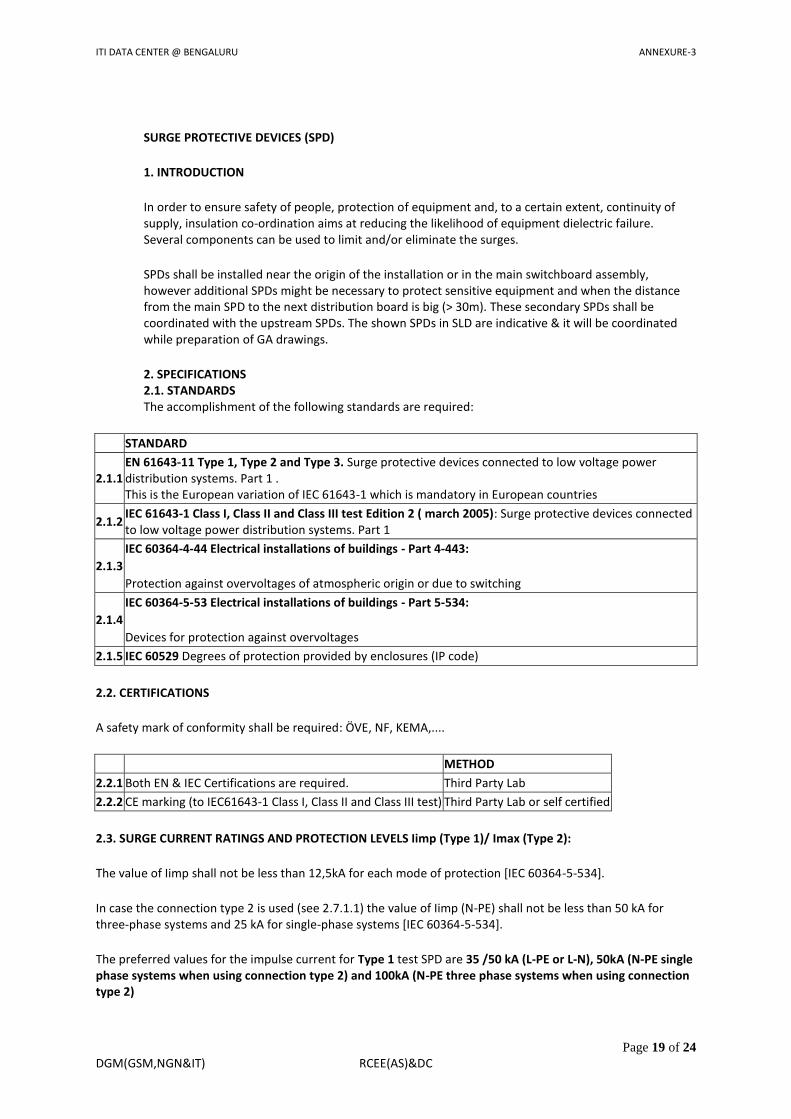
SURGE PROTECTIVE DEVICES (SPD)
1. INTRODUCTION
In order to ensure safety of people, protection of equipment and, to a certain extent, continuity of supply, insulation co-ordination aims at reducing the likelihood of equipment dielectric failure. Several components can be used to limit and/or eliminate the surges.
SPDs shall be installed near the origin of the installation or in the main switchboard assembly, however additional SPDs might be necessary to protect sensitive equipment and when the distance from the main SPD to the next distribution board is big (> 30m). These secondary SPDs shall be coordinated with the upstream SPDs. The shown SPDs in SLD are indicative & it will be coordinated while preparation of GA drawings.
2. SPECIFICATIONS 2.1. STANDARDS The accomplishment of the following standards are required:
STANDARD
2.1.1 EN 61643-11 Type 1, Type 2 and Type 3. Surge protective devices connected to low voltage power distribution systems. Part 1 . This is the European variation of IEC 61643-1 which is mandatory in European countries
2.1.2 IEC 61643-1 Class I, Class II and Class III test Edition 2 ( march 2005): Surge protective devices connected to low voltage power distribution systems. Part 1
2.1.3
IEC 60364-4-44 Electrical installations of buildings - Part 4-443:
Protection against overvoltages of atmospheric origin or due to switching
2.1.4
IEC 60364-5-53 Electrical installations of buildings - Part 5-534:
Devices for protection against overvoltages
2.1.5 IEC 60529 Degrees of protection provided by enclosures (IP code)
2.2. CERTIFICATIONS
A safety mark of conformity shall be required E, NF, KEMA,....
METHOD
2.2.1 Both EN & IEC Certifications are required. Third Party Lab
2.2.2 CE marking (to IEC61643-1 Class I, Class II and Class III test) Third Party Lab or self certified
2.3. SURGE CURRENT RATINGS AND PROTECTION LEVELS Iimp (Type 1)/ Imax (Type 2):
The value of Iimp shall not be less than 12,5kA for each mode of protection [IEC 60364-5-534].
In case the connection type 2 is used (see 2.7.1.1) the value of Iimp (N-PE) shall not be less than 50 kA for three-phase systems and 25 kA for single-phase systems [IEC 60364-5-534].
The preferred values for the impulse current for Type 1 test SPD are 35 /50 kA (L-PE or L-N), 50kA (N-PE single phase systems when using connection type 2) and 100kA (N-PE three phase systems when using connection type 2)

ITI DATA CENTER @ BENGALURU ANNEXURE-3
Page 20 of 24
DGM(GSM,NGN&IT) RCEE(AS)&DC
The preferred values for the maximum surge current rating Imax for Type 2 tests SPDs are 8kA, 20kA, 40kA and 65kA.
In:
The nominal discharge current In shall not be less than 5kA for each mode of protection [IEC 60364-5-534].
Up:
The protection level of the protective device (Up) shall not be higher than the level of overvoltage category II (2,5kV) [IEC 60364-4-443]. If sensitive electronics is to be protected the protection level shall not be higher than 1,5 kV.
Uc:
For a 230/400V network it is recommended the Maximum Continuous Operating System (Uc) to be no less than 340 V.
Response time:
The response time of Type I SPD shall be no more than 1μs, the response time of Type 2 SPD shall be no more than 25 ns.
2.4. MECHANICAL REQUIREMENTS
2.4.1 Housing Material
Housing material must conform the necessary standards (including self flame-extinguishing characteristics),
2.4.2 Required Housing Markings
Compliance to IEC 61643-1 Section 6.1.2
Test certification marks
2.4.3 Terminal Connection
35mm2 is preferred
2.4.5 End of Life Indicators
All products (except products to be connected N-PE) will have an End of Life visual indicator. The indication shall be LED or mechanical. If LED is used must be ON for normal operation (green color). When reach the end of life LED or mechanical indication must be Red.
2.4.6 Mounting Method
Standard Snap on 35 mm DIN Rail mounting.
2.4.7 Shock, Impact, Vibration
Reference IEC 60068
2.4.8 Enclosure Protection
Comply with IEC 60529 IP20 rating
5. 2.5. ENVIRONMENTAL REQUIREMENTS 6. 2.6. ELECTRICAL REQUIREMENTS
2.5.1 Minimum Operating Range -5 ° C to +40 ° C
2.5.2 Relative Humidity 5% to 90%
2.5.3 Altitude 2000 Meters minimum without derating
2.6.1 Remote Indication
Optional. When required use Dry Contacts (250 VAC 1.5A, 125V 3A desired, min. 0.25 Amps at 250V required).

ITI DATA CENTER @ BENGALURU ANNEXURE-3
Page 21 of 24
DGM(GSM,NGN&IT) RCEE(AS)&DC
2.6.2 Thermal Protection
Thermal fusing is required for MOVs. Not required for GDTs
2.6.3 Short circuit Protection
External dedicated circuit breaker to the SPD is required to guaranty the continuity of service and electrical installation safety in case of short circuit inside the SPDs.
2.6.4 System Frequency
47 Hz to 62 Hz
2.6.5 Breaker Coordination
Provide coordinated disconnect device requirements which will be put in the literature and on product as required by the manufacturer recommendations.

ITI DATA CENTER @ BENGALURU ANNEXURE-3
Page 22 of 24
DGM(GSM,NGN&IT) RCEE(AS)&DC
TECHNICAL SPECIFICATIONS OF ISOLATION TRANSFORMER
( 3PDS, K-1, 415V )
Environmental
Max. Operating Temperature 40o
C
Relative Humidity 95%
Altitude 1000m (de rate by 1% per 100m Between 1000 & 2000)
Storage Temperature 50o
C
Mechanical Characteristics
Dimension: Vendor to fill -
Ventilation. Forced Air
Colour Siemens Grey
Constructional Details CRCA with Load bearing members 2mm or better & Front Door 1.6mm, Rear Cover 1.2mm
Cable Entry Bottom Front
Protection Level IP-20
Electrical Characteristics
Standard applicable As per applicable clauses of IS-2026-Part I-2011 & Part II-2010
Input Voltage 415V, DELTA, 3 Phase,3 Wire
Input Voltage Tolerance +10% , -10%
Shielding No
Frequency. 50 Hz
Input Frequency Variation 5%
Class of Insulation Class H
Vector Group Dyn1
K-Rating K 1
Winding Material Copper
Output
Voltage 415V,STAR, 3 Phase,4 Wire
Output Load 150kVA,125KVA,100KVA,75KVA
Voltage Regulation (approximately) <2.5%
General Requirements
a) Over temp alarm indication @ 160°C
b) Inter connecting Cables Please specify
c) Termination COPPER with Platted bus bar
d) Gland Plate 3mm thick CRCA
Fuse protection All auxiliary circuits
Earthing bus bar 25x3 mm, AL
Isolation Transformer 150 KVA, 3PDS, 415V:415V, K1 1 No.
Switch Gear
Incomer Load Break Switch 320A, 4P 1 No. HPL / Scomec
Metering
I/P meter DM6100 to read V,I,F,pf 1 No.

ITI DATA CENTER @ BENGALURU ANNEXURE-3
Page 23 of 24
DGM(GSM,NGN&IT) RCEE(AS)&DC
Phase Indicators LED type Phase Ind. R, Y, B @ Input and Output 2 Set ESBEE
Additional Features
Over Temp Indication Over Temp Card with Indication 1 No
Soft Starter Soft starter (Auto / Manual) 1 No
I/P Manual OFF load Tap As per the Customer Requirement 1 No
Outgoing Load Break Switch 320A, 4P 1 No HPL / Scomec
Socket 3Pin Socket 5A 1 No L&T

ITI DATA CENTER @ BENGALURU ANNEXURE-3
Page 24 of 24
DGM(GSM,NGN&IT) RCEE(AS)&DC
PREFERRED LIST OF MAKES
Sr. No
DESCRIPTION MAKE
1 L.T. Cables (XLPE or PVC or otherwise) Polycab/ Asian/ Universal/ KEI
2 Wires PVC Insulated Copper(including Panel Wires) Finolex/Polycab/RR Kables
3 Cable Sockets/ Lugs Dowells / Jainsons
4 Cable Glands Comet/Dowells / Jainsons
5 PVC Moulded industrial power outlets C&S, Neptune, MGE
6 MCBs/ ELCBs/DBs L&T/Schneider/Siemens
7 MCCB L&T-Dsine /Schneider-Compact NSX /Siemens-3VL
8 ACB L&T- Omega U Power /Schneider- Masterpact NW/Siemens- 3WL
9 ATS SOCOMEC/ASCO
10 SPD L&T/SCHNEIDER /SIEMENS
11 L.T. Change Over Switches/SFU L&T/ HPL/Socomec
12 L.T. Power Capacitors Heavy Duty EPCOS/L&T/Schneider
13 Selector Switches Kaycee/Salzer
14 Ammeter/Voltmeter/P.F. Meter (Analog) AE/Rishabh
15 Digital Panel Meters Elmeasure/Conzerv/ Nippen
16 Current Transformers Resin cast AE/Indcoil/Rishabh
17 Indicating Lamps 22.5mm dia. (LED type) Teknic/ Schneider/ L & T
18 Connectors/ Terminal Blocks Connectwell/Elmex
19 PVC conduit and accessories Precision / BEC
20 Isolation Transformer Risabh/ Indus/ Herco/
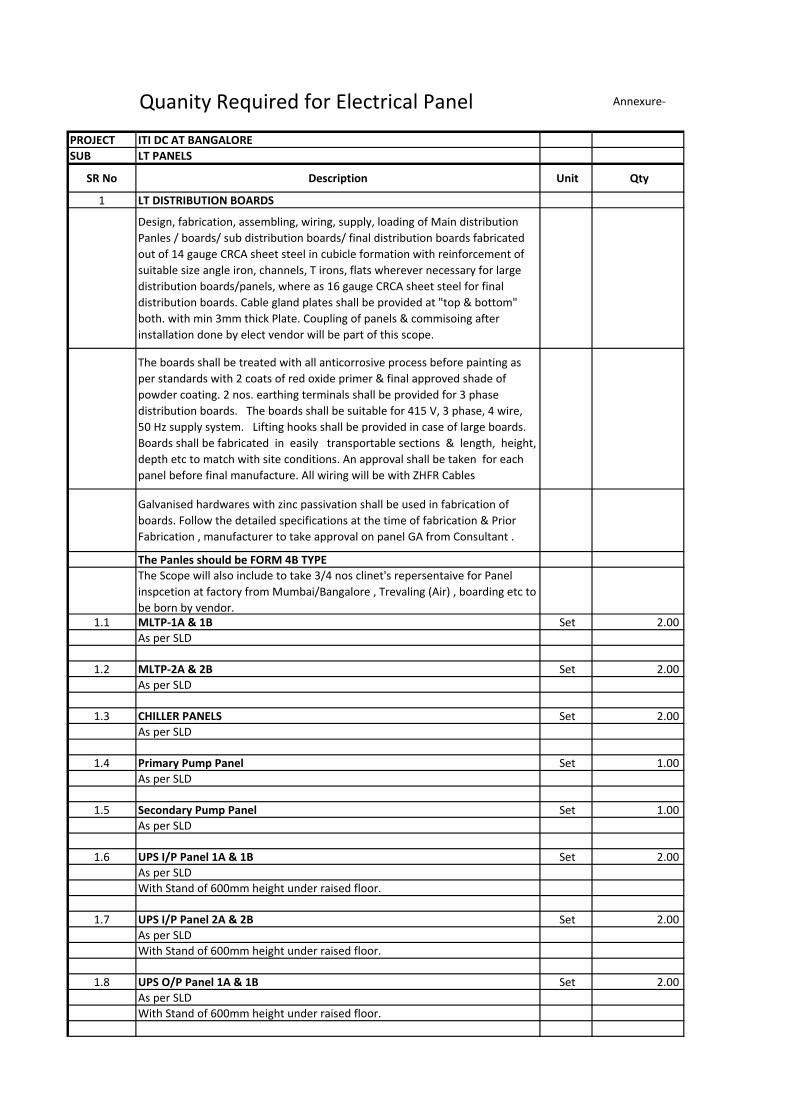
Quanity Required for Electrical Panel Annexure-
PROJECT ITI DC AT BANGALORE
SUB LT PANELS
SR No Description Unit Qty
1 LT DISTRIBUTION BOARDS
Design, fabrication, assembling, wiring, supply, loading of Main distribution
Panles / boards/ sub distribution boards/ final distribution boards fabricated
out of 14 gauge CRCA sheet steel in cubicle formation with reinforcement of
suitable size angle iron, channels, T irons, flats wherever necessary for large
distribution boards/panels, where as 16 gauge CRCA sheet steel for final
distribution boards. Cable gland plates shall be provided at "top & bottom"
both. with min 3mm thick Plate. Coupling of panels & commisoing after
installation done by elect vendor will be part of this scope.
The boards shall be treated with all anticorrosive process before painting as
per standards with 2 coats of red oxide primer & final approved shade of
powder coating. 2 nos. earthing terminals shall be provided for 3 phase
distribution boards. The boards shall be suitable for 415 V, 3 phase, 4 wire,
50 Hz supply system. Lifting hooks shall be provided in case of large boards.
Boards shall be fabricated in easily transportable sections & length, height,
depth etc to match with site conditions. An approval shall be taken for each
panel before final manufacture. All wiring will be with ZHFR Cables
Galvanised hardwares with zinc passivation shall be used in fabrication of
boards. Follow the detailed specifications at the time of fabrication & Prior
Fabrication , manufacturer to take approval on panel GA from Consultant .
The Panles should be FORM 4B TYPE
The Scope will also include to take 3/4 nos clinet's repersentaive for Panel
inspcetion at factory from Mumbai/Bangalore , Trevaling (Air) , boarding etc to
be born by vendor.1.1 MLTP-1A & 1B Set 2.00
As per SLD
1.2 MLTP-2A & 2B Set 2.00
As per SLD
1.3 CHILLER PANELS Set 2.00
As per SLD
1.4 Primary Pump Panel Set 1.00
As per SLD
1.5 Secondary Pump Panel Set 1.00
As per SLD
1.6 UPS I/P Panel 1A & 1B Set 2.00
As per SLD
With Stand of 600mm height under raised floor.
1.7 UPS I/P Panel 2A & 2B Set 2.00
As per SLD
With Stand of 600mm height under raised floor.
1.8 UPS O/P Panel 1A & 1B Set 2.00
As per SLD
With Stand of 600mm height under raised floor.

SR No Description Unit Qty
1.9 UPS O/P Panel 2A & 2B Set 2.00
As per SLD
With Stand of 600mm height under raised floor.
1.10 UPS O/P Panel 3A & 3B Set 2.00
As per SLD
With Stand of 600mm height under raised floor.
1.11 DC Panel 1A & 1B (21S) AT GROUND FLOOR Set 2.00
As per SLD
With Stand of 750mm height under raised floor.
1.12 DC Panel 2A & 2B (21S) AT 1ST FLOOR Set 2.00
As per SLD
With Stand of 750mm height under raised floor.
1.13 DC Panel 1A & 1B (F85) AT 1ST FLOOR Set 2.00
As per SLD
With Stand of 750mm height under raised floor.
1.14 DC Panel 2A & 2B (F85) AT 1ST FLOOR Set 2.00
As per SLD
With Stand of 750mm height under raised floor.
1.15 DC Panel 3A & 3B (F85) AT 1ST FLOOR Set 2.00
As per SLD
With Stand of 750mm height under raised floor.
1.16 DC Panel 4A & 4B (F85) AT 2ND FLOOR Set 2.00
As per SLD
With Stand of 750mm height under raised floor.
1.17 DC Panel 5A & 5B (F85) AT 3RD FLOOR Set 2.00
As per SLD
With Stand of 750mm height under raised floor.
1.18 PDU with 150KVA Isolation Transfomer Set 20.00
As per SLD
With Stand of 750mm height under raised floor.
1.19 PDU with 125KVA Isolation Transfomer Set 12.00
As per SLD
With Stand of 750mm height under raised floor.
1.20 PDU with 100KVA Isolation Transfomer Set 66.00
As per SLD
With Stand of 750mm height under raised floor.
1.21 PDU with 75KVA Isolation Transfomer Set 2.00
As per SLD
With Stand of 750mm height under raised floor.
1.22 SUB PANEL 1A& 1B AT 21S BLOCK Set 2.00
As per SLD
With Stand of 750mm height under raised floor.
1.23 SUB PANEL 2A& 2B AT F85 BLOCK Set 2.00
As per SLD
With Stand of 750mm height under raised floor.
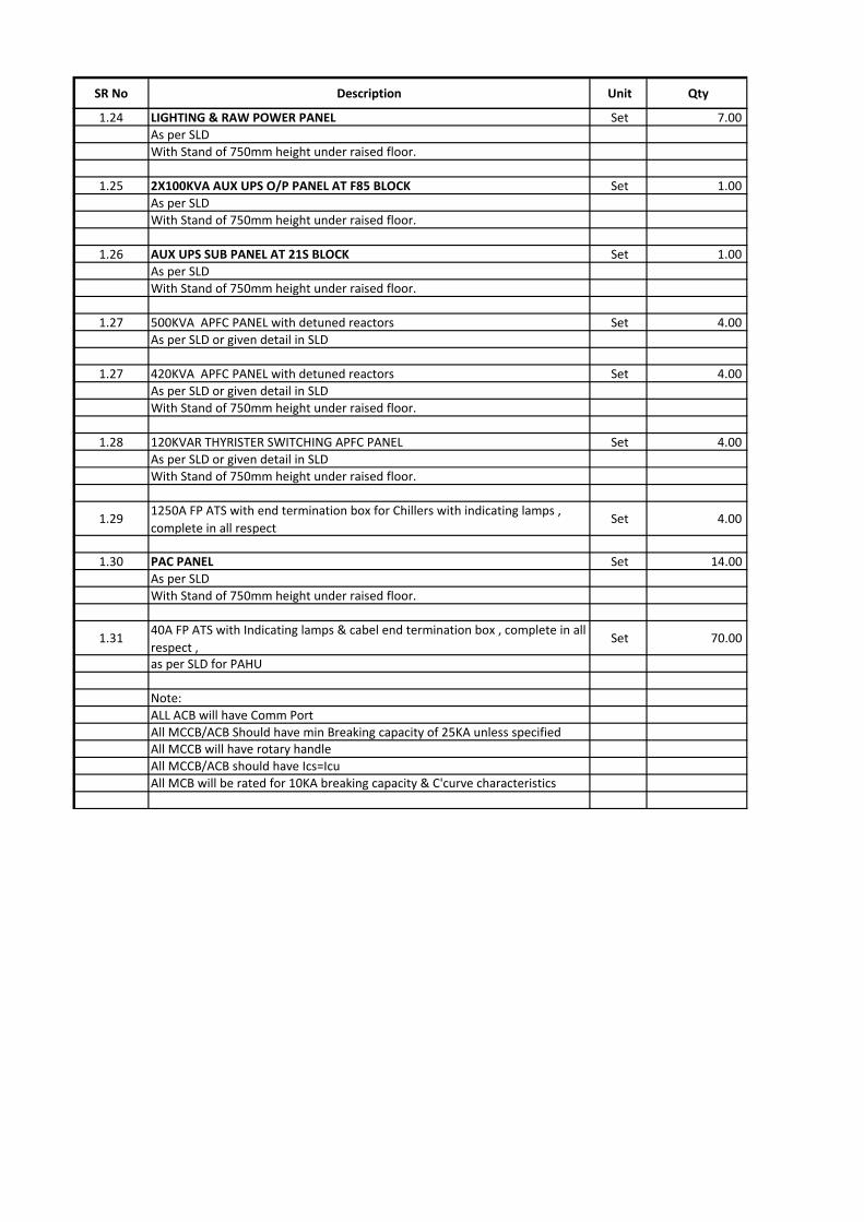
SR No Description Unit Qty
1.24 LIGHTING & RAW POWER PANEL Set 7.00
As per SLD
With Stand of 750mm height under raised floor.
1.25 2X100KVA AUX UPS O/P PANEL AT F85 BLOCK Set 1.00
As per SLD
With Stand of 750mm height under raised floor.
1.26 AUX UPS SUB PANEL AT 21S BLOCK Set 1.00
As per SLD
With Stand of 750mm height under raised floor.
1.27 500KVA APFC PANEL with detuned reactors Set 4.00
As per SLD or given detail in SLD
1.27 420KVA APFC PANEL with detuned reactors Set 4.00
As per SLD or given detail in SLD
With Stand of 750mm height under raised floor.
1.28 120KVAR THYRISTER SWITCHING APFC PANEL Set 4.00
As per SLD or given detail in SLD
With Stand of 750mm height under raised floor.
1.291250A FP ATS with end termination box for Chillers with indicating lamps ,
complete in all respect Set 4.00
1.30 PAC PANEL Set 14.00
As per SLD
With Stand of 750mm height under raised floor.
1.3140A FP ATS with Indicating lamps & cabel end termination box , complete in all
respect , Set 70.00
as per SLD for PAHU
Note:
ALL ACB will have Comm Port
All MCCB/ACB Should have min Breaking capacity of 25KA unless specifiedAll MCCB will have rotary handle
All MCCB/ACB should have Ics=Icu
All MCB will be rated for 10KA breaking capacity & C'curve characteristics

Note: Makes specified in the BOQ supercedes this List.
All makes shall be ISI marked wherever applicable.
Sr.
NoDESCRIPTION MAKE
1 L.T. Cables (XLPE or PVC or otherwise) Polycab/ Asian/ Universal/ KEI
2 Wires PVC Insulated Copper(including Panel Wires) Finolex/Polycab/RR Kables
3 Cable Sockets/ Lugs Dowells / Jainsons
4 Cable Glands Comet/Dowells / Jainsons
5 PVC Moulded industrial power outlets C&S, Neptune, MGE
6 MCBs/ ELCBs/DBs L&T/Schneider/Siemens
7 MCCB L&T-Dsine /Schneider-Compact NSX /Siemens-3VL
8 ACBL&T- Omega U Power /Schneider- Masterpact
NW/Siemens- 3WL9 ATS SOCOMEC/ASCO
10 SPD L&T/SCHNEIDER /SIEMENS
11 L.T. Change Over Switches/SFU L&T/ HPL/Socomec
12 L.T. Power Capacitors Heavy Duty EPCOS/L&T/Schneider
13 Selector Switches Kaycee/Salzer
14 Ammeter/Voltmeter/P.F. Meter (Analog) AE/Rishabh
15 Digital Panel Meters Elmeasure/Conzerv/ Nippen
16 Current Transformers Resin cast AE/Indcoil/Rishabh
17 Indicating Lamps 22.5mm dia. (LED type) Teknic/ Schneider/ L & T
18 Connectors/ Terminal Blocks Connectwell/Elmex
19 PVC conduit and accessories Precision / BEC
20 Isolation Transformer Risabh/ Indus/ Herco/
PREFERRED LIST OF MAKES [ ELECTRICAL WORK-LT]