SPECIALTY MATE R IALS, INC. · PDF fileSPECIALTY MATE R IALS, INC. ... Hy-Bor® for...
17
SPECIALTY MATERIALS, INC. Manufacturers of Boron and SCS Silicon Carbide Fibers and Boron Nanopowder Hy-Bor ® for Advanced Hat-stiffened Aircraft Structures A design and verification study was undertaken by the Boeing Phantom Works, St. Louis, MO to evaluate the potential structural benefits and cost impact of the selective use of Hy-Bor ® hybrid boron-graphite prepreg tape in an advanced aircraft design. Emerging composite hat stiffened skin designs for combat aircraft are using a design approach where the inner moldline skin, web, and cap plies are continuous. This design approach has shown a performance benefit over discrete flange concepts, especially in high compression load applications. The objective of this study was to determine the structural efficiency benefits of Hy-Bor ® in composite material design and to perform a manufacturing cost analysis. Using loads typical of a highly-loaded compression region of an advanced aircraft wing skin, this analysis task used Boeing software tools to optimize a composite baseline hat section design. Typical geometric parameters considered for optimization are shown in the Figure 1. The baseline design consisted of Cytec’s T40-800/5215 tape and T300 5HS/5215 fabric. Starting with the optimized baseline design, Hy-Bor ® was integrated into the cap and base regions to develop an optimized Hy-Bor ® reinforced hat design. It was expected that the Hy-Bor® reinforced hat design would allow for an increase in hat spacing (Figure 2), a reduction in skin thickness, or reduction in hat size leading to significant weight savings. In addition to determining potential weight savings, a manufacturing cost comparison between the baseline and Hy-Bor ® reinforced concepts was conducted. Cap Width Base Width Base Thickness Web Thickness Cap Thickness Height Skin Thickness Nugget Filler Potential Hy-Bor Application Web Angle Figure 1 - Baseline & Hy-Bor ® Reinforced Design Concepts
Transcript of SPECIALTY MATE R IALS, INC. · PDF fileSPECIALTY MATE R IALS, INC. ... Hy-Bor® for...

SPECIALTY MATERIALS, INC.Manufacturers of Boron and SCS Silicon Carbide Fibers and Boron Nanopowder
Hy-Bor® for Advanced Hat-stiffened Aircraft Structures A design and verification study was undertaken by the Boeing Phantom Works, St. Louis, MO to evaluate the potential structural benefits and cost impact of the selective use of Hy-Bor® hybrid boron-graphite prepreg tape in an advanced aircraft design.
Emerging composite hat stiffened skin designs for combat aircraft are using a design approach where the inner moldline skin, web, and cap plies are continuous. This design approach has shown a performance benefit over discrete flange concepts, especially in high compression load applications. The objective of this study was to determine the structural efficiency benefits of Hy-Bor® in composite material design and to perform a manufacturing cost analysis. Using loads typical of a highly-loaded compression region of an advanced aircraft wing skin, this analysis task used Boeing software tools to optimize a composite baseline hat section design. Typical geometric parameters considered for optimization are shown in the Figure 1. The baseline design consisted of Cytec’s T40-800/5215 tape and T300 5HS/5215 fabric. Starting with the optimized baseline design, Hy-Bor® was integrated into the cap and base regions to develop an optimized Hy-Bor® reinforced hat design. It was expected that the Hy-Bor® reinforced hat design would allow for an increase in hat spacing (Figure 2), a reduction in skin thickness, or reduction in hat size leading to significant weight savings. In addition to determining potential weight savings, a manufacturing cost comparison between the baseline and Hy-Bor® reinforced concepts was conducted.
Cap Width
Base WidthBase Thickness
WebThickness
Cap Thickness
Height
Skin Thickness
Nugget Filler
Potential Hy-Bor Application
Web Angle
Figure 1 - Baseline & Hy-Bor® Reinforced Design Concepts

SPECIALTY MATERIALS, INC.Manufacturers of Boron and SCS Silicon Carbide Fibers and Boron Nanopowder
Baseline Skin Panel Hat Spacing
Hy-Bor Rinforced Skin Panel Hat Spacing
Figure 2 - Software Optimization at Panel Level
Based on initial design requirements, the baseline skin thickness was set at 0.13-inch thickness (min.) with a mandrel height of 2" and mandrel cap width of 1.5". Based on these requirements and design loads, a baseline concept was determined. Using this baseline concept, Hy-Bor® plies were then added to both the hat cap and the skin area under the hat. Five variations in skin laminates ranging from 0.1302" - 0.141" in thickness were considered. The addition of Hy-Bor® plies in into the skin had no effect on weight, mostly due to the closeness of the skin panel to the structure’s neutral axis. A weight savings of only 1% (0.2 lbs for the 17.5 lb study panel section) was realized. Thinner skin laminates, ranging from 0.1192 to 0.1248-inch, were then evaluated. With Hy-Bor® plies only in the cap regions of the hats, the weight savings were still in the 1% range. The hat height was then varied between 1 and 2-inches at 0.25-inch increments. The hat cap width was varied in the same manner. The hat web angle remained the same since this angle was found to be optimum based on studies conducted on previous Boeing programs. Three skin laminates at two thicknesses (0.1194 and 0.1302-inch) were considered. As before, Hy-Bor® plies were placed in the cap of the hat. At this point a weight savings of 0.8 lbs or nearly 5% on a panel basis was realized. Final panel geometries for the Baseline and Hy-Bor® designs are shown in Figure 3. Considering an advanced aircraft platform with approximately 3000 lbs integrated hat-stiffened composite structure, this translates into an appreciable 150 lbs of weight savings. A potential secondary benefit would be the 28% smaller hat height that was obtained. In a wing portion of such a design the smaller hat sections could allow increased fuel capacity.

SPECIALTY MATERIALS, INC.Manufacturers of Boron and SCS Silicon Carbide Fibers and Boron Nanopowder
t (in) Layup t (in) Layup Length (in) Width (in) Stiffeners
0.119445
c, 0
c, +45, -45, 03, 90,
03, -45, +45, 0c, 45
c 0.06 45c, 0
c, 0
c, 45
c 40 45 6
Skin Web PanelCommon Features
t (in) Layup Reinforcement Base (in) Cap (in) Height (in)
Baseline 0.1032 45c, 03, 0
c, 02, 0
c, 03, 45
c 0° Tape 1.62 1 1.75 17.5
Hy-Bor 0.1149 45c, 0
H3, 0
c, 0
H3, 0
c, 0
H3, 45
c 0° Hy-Bor 1.44 1 1.25 16.7
Weight (lbs)
Cap MandrelOptimized Features
Configuration
Skin
Web Cap
MandrelBase
MandrelCap
MandrelHeight
45° Cloth
0° Cloth
Reinforcement
Tape Plies Skin
Web Cap
MandrelBase
MandrelCap
MandrelHeight
45° Cloth
0° Cloth
Reinforcement
Tape Plies
C = cloth H = Hy-Bor
Figure 3 – Optimization Summary
A cost comparison was completed for the baseline hat stiffened panel design and the Hy-Bor® hat stiffened panel design. Design and manufacturing information for each design was loaded into Boeing’s DFM software and labor outputs were compared. Inputs

SPECIALTY MATERIALS, INC.Manufacturers of Boron and SCS Silicon Carbide Fibers and Boron Nanopowder
consisted of the number of skin plies and skin lay-up information, and the number of hats and hat ply lay-up information. It was assumed that the same outer mold line (OML) tool would be used for both designs and would not impact the cost comparison; therefore, only mandrel tooling was estimated. Estimates for the mandrel tooling were made by tool engineering rather than using the DFM software. A summary of the cost comparison breakdown between the baseline and Hy-Bor® designs is presented in Figure 4. Assumptions used in the cost estimating process are listed below:
1. The part lay-up was broken down as follows to get the most accurate estimate: Skin -- Two plies of cloth and 11 plies of tape Hat web -- Two plies of cloth wrapped around the mandrel Hat cap -- 5215 tape or Hy-Bor® tape depending on which design Over lay plies -- 2 Cloth plies laid over the skin and hats 2. Cytec material cost per pound for small quantities supplied by Cytec: T40-800/5215 tape -- $81.63/lb T300 5HS/5215 cloth – $49.08/lb 3. Calculations were made to determine a cost in $/lb for Hy-Bor® prepreg with a 5215
resin as follows: A. Cost of T40-800/5215 tape was converted from $81.63/lb to $1.73/LF $81.63/lb x 0.055lb/in3 = $4.55/in3 $4.55/in3 x 0.0054in (5215 tape thickness) x 144in2/ft2 x 0.5ft
(width of tape) = $1.73/LF B. SMI cost of $17.75/LF and added to cost of 5215 tape of $1.73/LF 5215 Hy-Bor = $19.48/LF C. Cost of 5215 Hy-Bor® was converted from $19.48/LF to $693/lb $19.48/LF x 1LF/12in length x 6in width x 0.0061in thickness = $19.48/LF x 1/LF/0.4392in3 x 1in3/0.064lb = $693/lb 4. There were no manufacturing differences between the two designs; the only
differences were the hat cap material and hat sizes. The DFM results show a slight cost savings for the Hy-Bor® design because of less 5215 material cost and slightly

SPECIALTY MATERIALS, INC.Manufacturers of Boron and SCS Silicon Carbide Fibers and Boron Nanopowder
less labor (due to smaller hat size) but a significant cost increase in the hat cap material as compared to the baseline hat cap material cost.
Baseline Design Hy-Bor Design Hy-Bor Cost Increase
SKINMaterial Cost $631.00 $631.00 $0.00
Labor cost @ $150/hr $781.00 $781.00 $0.00
Total skin cost $1,412.00 $1,412.00 $0.00
HATS*Material Cost $166.20 $680.40 $514.20
Labor Cost @ $150/hr $3,612.00 $3,726.00 $114.00
Total Hat cost $3,778.20 $4,406.40 $628.20
TOP 2 PLIES OVER HATS AND SKIN**
Material Cost $200.00 $185.00 -$15.00
Labor cost @ $150/hr $414.00 $395.00 -$19.00
Total Top 2 Plies Cost $614.00 $580.00 -$34.00
TOTAL MATERIAL COST $997.20 $1,496.40 $499.20
TOTAL LABOR COST $4,807.00 $4,902.00 $95.00
TOTAL COST $5,804.20 $6,398.40 $594.20
*Added cost of web plies and cap plies and multiplied by 6 hats
** These are the 2 cloth plies that go over the hats and continue over the skin. They were not
accounted for in the skin or hats.
Figure 4 - Cost Comparison Summary

SPECIALTY MATERIALS, INC.Manufacturers of Boron and SCS Silicon Carbide Fibers and Boron Nanopowder
The structure used as the basis of this trade study represented an advanced airframe concept containing approximately 3,000 lbs. of hat-stiffened skin composite structure. Application of Hy-Bor® to the skins of the structure did not result in a significant weight savings; however, a weight saving of 5% (150 lbs. total) was achieved with the inclusion of Hy-Bor® in the hat components and appropriate resizing. The reduction in hat depth resulting from increased compression properties in the cap region provides an opportunity for significant increase in fuel capacity in the wing portions of the structure. On a total baseline structural weight of 3,000 lbs., the projected materials and manufacturing cost to save 150 lbs. would be $127,575, or $850.50/lb of weight saved. The value of increased internal wing volume for fuel was not estimated.
In the verification portion of this study a Hy-Bor reinforced, hat stiffened panel (Figure 5) was fabricated and machined to produce three hat stiffened panel subcomponents for structural testing in combined compression-pressure.
27.75”
40.0”
7.3”
Panel width allows for subcomponent machining
Subcomponent width is 6.5”. 0.4” added to eachside for simple-supportfixturing.
Figure 5 - Subcomponent Plan for Hat-Stiffened Panel

SPECIALTY MATERIALS, INC.Manufacturers of Boron and SCS Silicon Carbide Fibers and Boron Nanopowder
The panel fabrication consisted of a series of debulking operations to remove entrapped air and aid in compaction. Figure 6 shows one such operation that occurred after the majority of the skin, hat mandrels, inner wrap hat plies, and first three Hy-Bor cap plies were located.
Figure 6 - Hat-Stiffened Panel During Typical Debulking Operation (Skin, Hat Mandrels, Inner Wrap Hat Plies and First Three Hy-Bor Cap Plies in Place)
After curing, the panel underwent a post cure at 350°F for four hours. The hat
ends were trimmed and the panel has been sent to NDI prior to subcomponent extraction. The completed stiffened panel is show from the inner mold line and outer mold line in Figures 7 and 8, respectively.

SPECIALTY MATERIALS, INC.Manufacturers of Boron and SCS Silicon Carbide Fibers and Boron Nanopowder
Figure 7 - Inner Mold Line of Panel with Trimmed Hats Prior to NDI
Figure 8 - Outer Mold Line of Panel with Trimmed Hats Prior to NDI Ultrasonic nondestructive inspection revealed that no significant indications were
present and the panel was of production quality. The test subcomponents were then machined from the panel (Figure 9) and configured with load adapters in preparation for instrumentation and test (Figure 10).

SPECIALTY MATERIALS, INC.Manufacturers of Boron and SCS Silicon Carbide Fibers and Boron Nanopowder
Figure 9 - Machined Subcomponents

SPECIALTY MATERIALS, INC.Manufacturers of Boron and SCS Silicon Carbide Fibers and Boron Nanopowder
Figure 10 - First Subcomponent Ready for Test (Load Adapters, Tension Pads, and Instrumentation in Place)
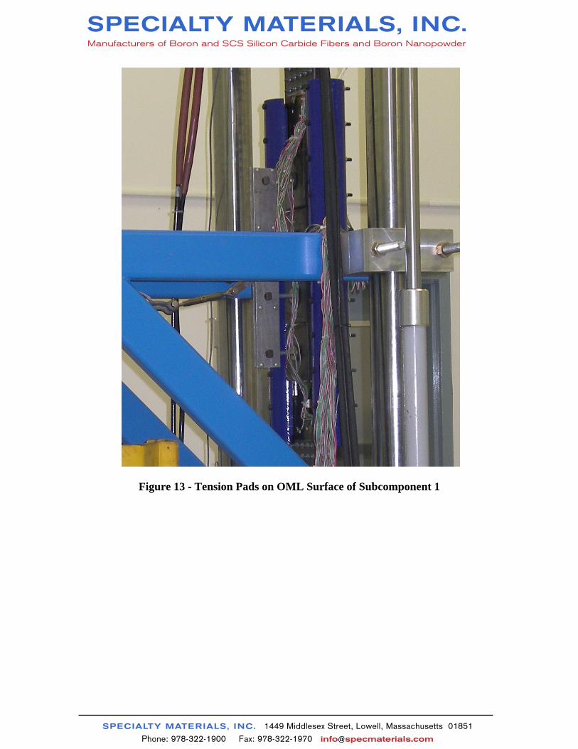
The compression test set-up is shown in Figure 11 with a close up of the subcomponent from the inner moldline (IML), stiffener side, shown in Figure 12. The simulated air pressure of 5 psi was applied to the tension pads, Figure 13, through a dead-weight setup which simply utilized a mobile hydraulic lift which held the dead weight in place and slowing released the weight to apply load to the tension pads (Figure 14).
Figure 11 - Subcomponent Test Setup

SPECIALTY MATERIALS, INC.Manufacturers of Boron and SCS Silicon Carbide Fibers and Boron Nanopowder
Figure 12 - Close-up of Subcomponent 1 during Test IML (Stiffener Side)
SPECIALTY MATERIALS, INC.Manufacturers of Boron and SCS Silicon Carbide Fibers and Boron Nanopowder
Figure 13 - Tension Pads on OML Surface of Subcomponent 1

SPECIALTY MATERIALS, INC.Manufacturers of Boron and SCS Silicon Carbide Fibers and Boron Nanopowder
Figure 14 - Simulated Pressure Applied Through Dead Weight Setup
Design ultimate compression load (DUL) for the subcomponent was 16, 500 lbs. Subcomponent 1 achieved that level with no audible indications of failure events. Continuation of the test resulted in failure at 22, 555 lbs of compression load with no audible indications of failure until the failure load was reached; audible cracking and associated response in strain data indicated failure had occurred. Failure occurred in the hat run-out region at the top of the subcomponent, Figure 15. This failure is typical of this advanced hat design concept which precludes failure from occurring at the hat flange/skin location at lower loads since there is no discrete hat flange/skin interface.

SPECIALTY MATERIALS, INC.Manufacturers of Boron and SCS Silicon Carbide Fibers and Boron Nanopowder
Figure 15 - Subcomponent 1 Failure – Hat Run-Out Region
The compression with pressure load testing was subsequently conducted on subcomponents 2 and 3. The failing loads for all three subcomponents were:
• Subcomponent 1 22,560 pounds • Subcomponent 2 16,180 pounds • Subcomponent 3 32,080 pounds
While this is a considerable spread in the test results, the failure mode, delamination in
the hat taper run-outs, was similar for all subcomponents. Failure locations for each of the subcomponents relative to key strain gage locations are shown in Figure 16. Axial strain gage response on each side of the hat run-out at each end of the subcomponents is shown in Figures 17 through 19 for Subcomponents 1, 2, and 3, respectively. The deviation in strain at loading onset is due to the applied 5 psi pressure load.
CLCL
8A8A
1717 11A11A1818
14A14A 7A7A
12A12A
13A13A
Subcomponent 1Hat Taper Run-out Failure
Location
Subcomponents 2 & 3Hat Taper Run-out Failure
Location
Odd Numbered Strain Gages on Hat Side
Figure 16 - Subcomponent Failure Location

SPECIALTY MATERIALS, INC.Manufacturers of Boron and SCS Silicon Carbide Fibers and Boron Nanopowder
Subcomponent 1
-24000
-22000
-20000
-18000
-16000
-14000
-12000
-10000
-8000
-6000
-4000
-2000
0-3500-3000-2500-2000-1500-1000-5000500100015002000
Strain μin/in
Loadlbs
Gage 12A PAD SIDE
Gage 17 HAT SIDE
Gage 7A HAT SIDE
Gage 11A HAT SIDE
Gage 18 PAD SIDE
Gage 8A PAD SIDE
Gage 13A HAT SIDE
Gage 14A PAD SIDE
12A12A
8A8A1717
7A7A
11A11A
1818
14A14A13A13A
Figure 17 - Axial Strain Gage Results – Subcomponent 1
Subcomponent 2-24000
-22000
-20000
-18000
-16000
-14000
-12000
-10000
-8000
-6000
-4000
-2000
0-3000-2500-2000-1500-1000-500050010001500
Strain μin/in
Loadlbs
Gage 12A PAD SIDE
Gage 17 HAT SIDE
Gage 7A HAT SIDE
Gage 11A HAT SIDE
Gage 18 PAD SIDE
Gage 8A PAD SIDE
Gage 13A HAT SIDE
Gage 14A PAD SIDE
8A8A 171711A11A181814A14A
7A7A
12A12A
13A13A
Figure 18 - Axial Strain Gage Results – Subcomponent 2

SPECIALTY MATERIALS, INC.Manufacturers of Boron and SCS Silicon Carbide Fibers and Boron Nanopowder
Subcomponent 3
-36000
-32000
-28000
-24000
-20000
-16000
-12000
-8000
-4000
0-3500-3000-2500-2000-1500-1000-50005001000
Strain μin/in
Loadlbs
Gage 12A PAD SIDE
Gage 17 HAT SIDE
Gage 7A HAT SIDE
Gage 11A HAT SIDE
Gage 18 PAD SIDE
Gage 8A PAD SIDE
Gage 13A HAT SIDE
Gage 14A PAD SIDE
8A8A
1717
11A11A
1818
14A14A
7A7A
12A12A
13A13A
Figure 19 - Axial Strain Gage Results – Subcomponent 3
The strain response indicates the presence of beam-column action which is expected for combined compression-pressure loading. The results indicate that the degree of bending strain caused by beam-column action has a profound effect on failure load. It should also be noted that the strain results indicate that subcomponents’ stiffness were similar.
Prior to this project Boeing conducted an in-house program to develop an advanced all
carbon/epoxy concept that was designed to similar loading and tested in compression with 5 psi simulated pressure. Although all the details of this design cannot be disclosed in this paper, enough detail can be shown to make a strength vs. unit volume weight comparison, Figure 20. It should be noted that the highest (32,080 lb.) Hy-Bor test result was used in the comparison. Also, the advanced hat concept value is based on one test.
Key information that can be observed from this comparison is:
• Strengths per Unit Volume Weight are very similar ~ 500 Kips/lb. • Hy-Bor design is over 8% lighter. • Reduced hat height will result in increased fuel or payload capacity.

SPECIALTY MATERIALS, INC.Manufacturers of Boron and SCS Silicon Carbide Fibers and Boron Nanopowder
Hy-Bor Hat
Advanced Concept Hat
7.20”
2.10”
7.3”
1.48”
Area = 1.144 in2
Area = 1.255 sq in
ρC/E = 0.055lb/in3 ρHy-Bor = 0.064lb/in3
Unit Volume Weight= 0.0634 lbs
Unit Volume Weight= 0.0690 lbs
• Carbon/Epoxy = 1.089 in2• Hy-Bor = 0.055 in2
Highest Failing Load= 32.08 kips
Highest Failing Load= 34.60 kips
Strength/UVW= 506 kips/lb
Strength/UVW= 501 kips/lb
Figure 20 - Strength per Unit Volume Comparison Conclusion This design and verification study was conducted to demonstrate the structural and cost effectiveness of hybrid boron/graphite composite tape (Hy-Bor®) in an advanced composite hat stiffened skin aircraft structure. The design study revealed that, for the specific structure in the study, Hy-Bor could be used in the cap portion of the integral hat stiffeners to reduce weight by 5%, at an additional cost of $851 per pound of weight saved. An additional benefit to the study design was a 28% reduction in hat height that might translate into a usable volume increase. The verification portion of the study confirmed the ability to meet and exceed the DUL. Comparison to a baseline design with equal strength per unit volume capability reveals an 8% weight savings.